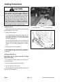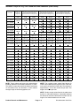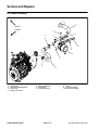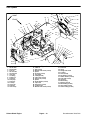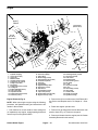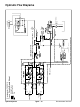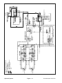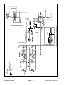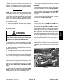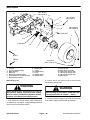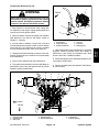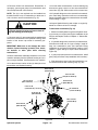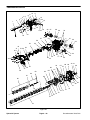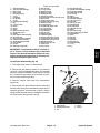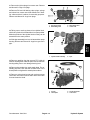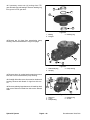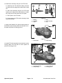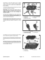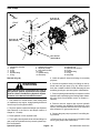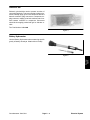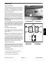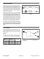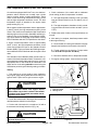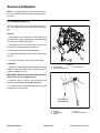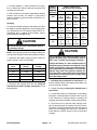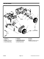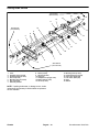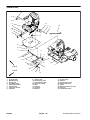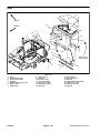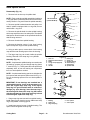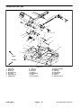
1
PART NO. 07150SL
Service Manual
Groundsmaster 7200/7210
Preface
The purpose of this publication is to provide the service
technician with information for troubleshooting, testing,
and repair of major systems and components on the
Groundsmaster 7200 and 7210.
REFER TO THE OPERATOR’S MANUAL FOR OPERATING,
MAINTENANCE
AND
ADJUSTMENT
INSTRUCTIONS. Space is provided in Chapter 2 of this
book to insert the Operator’s Manual and Parts Catalog
for your machine. Replacement Operator’s Manuals
and Parts Catalogs are available on the internet at
www.Toro.com or by sending complete Model and
Serial Number to:
The Toro Company
Attn. Technical Publications
8111 Lyndale Avenue South
Bloomington, MN 55420–1196
This safety symbol means DANGER, WARNING
or CAUTION, PERSONAL SAFETY INSTRUCTION. When you see this symbol, carefully read
the instructions that follow. Failure to obey the
instructions may result in personal injury.
NOTE: A NOTE will give general information about the
correct operation, maintenance, service, testing or
repair of the machine.
IMPORTANT: The IMPORTANT notice will give important instructions which must be followed to prevent damage to systems or components on the
machine.
The Toro Company reserves the right to change product
specifications or this publication without notice.
The Toro Company – 2007
This page is intentionally blank.
Groundsmaster 7200/7210
Chapter 2 – Product Records and Maintenance
Product Records . . . . . . . . . . . . . . . . . . . . . . . . . . .
Maintenance . . . . . . . . . . . . . . . . . . . . . . . . . . . . . . .
Equivalents and Conversions . . . . . . . . . . . . . . . .
Torque Specifications . . . . . . . . . . . . . . . . . . . . . . .
2–1
2–1
2–2
2–3
Chapter 3 – Kubota Diesel Engine
Specifications . . . . . . . . . . . . . . . . . . . . . . . . . . . . . . 3 – 2
General Information . . . . . . . . . . . . . . . . . . . . . . . . 3 – 4
Adjustments . . . . . . . . . . . . . . . . . . . . . . . . . . . . . . . 3 – 5
Service and Repairs . . . . . . . . . . . . . . . . . . . . . . . . 3 – 6
KUBOTA WORKSHOP MANUAL, DIESEL ENGINE,
05 SERIES
Chapter 6 – Chassis
Specifications . . . . . . . . . . . . . . . . . . . . . . . . . . . . . . 6 – 2
General Information . . . . . . . . . . . . . . . . . . . . . . . . 6 – 3
Service and Repairs . . . . . . . . . . . . . . . . . . . . . . . . 6 – 4
Chapter 7 – Cutting Deck
General Information . . . . . . . . . . . . . . . . . . . . . . . . 7 – 2
Factors That Can Affect Cutting Performance . . 7 – 3
Service and Repairs . . . . . . . . . . . . . . . . . . . . . . . . 7 – 5
Chapter 8 – Foldout Diagrams
Specifications . . . . . . . . . . . . . . . . . . . . . . . . . . . . . . 4 – 2
General Information . . . . . . . . . . . . . . . . . . . . . . . . 4 – 3
Hydraulic Schematics . . . . . . . . . . . . . . . . . . . . . . . 4 – 9
Hydraulic Flow Diagrams . . . . . . . . . . . . . . . . . . . 4 – 10
Special Tools . . . . . . . . . . . . . . . . . . . . . . . . . . . . . 4 – 18
Troubleshooting . . . . . . . . . . . . . . . . . . . . . . . . . . . 4 – 20
Testing . . . . . . . . . . . . . . . . . . . . . . . . . . . . . . . . . . . 4 – 24
Service and Repairs . . . . . . . . . . . . . . . . . . . . . . . 4 – 43
PARKER TORQMOTORTM SERVICE PROCEDURE
(TC, TB, TE, TJ, TF, TG, TH AND TL SERIES)
Hydraulic Schematics . . . . . . . . . . . . . . . . . . . . . . . 8 – 3
Electrical Schematics . . . . . . . . . . . . . . . . . . . . . . . 8 – 7
Electrical Circuit Diagrams . . . . . . . . . . . . . . . . . . . 8 – 9
Wire Harness Drawings . . . . . . . . . . . . . . . . . . . . 8 – 13
Foldout
Diagrams
Cutting
Deck
Chassis
Chapter 4 – Hydraulic System
Product Records
and Maintenance
Electrical Schematics and Diagrams . . . . . . . . . . 5 – 1
Special Tools . . . . . . . . . . . . . . . . . . . . . . . . . . . . . . 5 – 2
Troubleshooting . . . . . . . . . . . . . . . . . . . . . . . . . . . . 5 – 4
Electrical System Quick Checks . . . . . . . . . . . . . . 5 – 8
Component Testing . . . . . . . . . . . . . . . . . . . . . . . . 5 – 10
Service and Repairs . . . . . . . . . . . . . . . . . . . . . . . 5 – 28
Kubota
Diesel Engine
General Safety Instructions . . . . . . . . . . . . . . . . . . 1 – 1
Jacking Instructions . . . . . . . . . . . . . . . . . . . . . . . . . 1 – 4
Hydraulic
System
Chapter 5 – Electrical System
Electrical
System
Chapter 1 – Safety
Safety
Table Of Contents
Groundsmaster 7200/7210
This page is intentionally blank.
Groundsmaster 7200/7210
Safety
Table of Contents
GENERAL SAFETY INSTRUCTIONS . . . . . . . . . . . .
Supervisor’s Responsibilities . . . . . . . . . . . . . . . . .
Before Operating . . . . . . . . . . . . . . . . . . . . . . . . . . . .
While Operating . . . . . . . . . . . . . . . . . . . . . . . . . . . .
Maintenance and Service . . . . . . . . . . . . . . . . . . . .
JACKING INSTRUCTIONS . . . . . . . . . . . . . . . . . . . . .
1
1
2
2
3
4
General Safety Instructions
Groundsmaster 7200 and 7210 machines meet or exceed safety standard specifications as identified in the
Operator’s Manual. Although hazard control and accident prevention are dependent partially upon the design
and configuration of the machine, these factors are also
dependent upon the awareness, concern and proper
training of the personnel involved in the operation, transport, maintenance and storage of the machine. Improper use or maintenance by the operator or owner of the
machine can result in injury. To reduce the potential for
any injury, comply with the following safety instructions
as well as information found in the Operator’s Manual.
WARNING
To reduce the potential for injury or death,
comply with the following safety instructions.
Supervisor’s Responsibilities
1. Make sure operators are thoroughly trained and familiar with the Operator’s Manual, Operator Training
DVD and all of the operating and safety decals on the
machine.
2. Be sure to establish your own special procedures
and work rules for unusual operating conditions (e.g.
Groundsmaster 7200/7210
slopes too steep for machine operation). Survey mowing site completely to determine which hills can be
operated on safely. When performing this site survey,
always use common sense and take into consideration
the turf condition and the rollover risk. To perform a site
survey, follow the procedure outlined in the Operator’s
Manual.
Page 1 – 1
Safety
Safety
Chapter 1
Before Operating
1. Review and understand the contents of the Operator’s Manual and Operator Training DVD before starting
and operating the machine. Become familiar with the
controls and know how to stop the machine and engine
quickly. A replacement Operator’s Manual is available
on the Internet at www.Toro.com or by sending the complete model and serial number to:
5. Since fuel is highly flammable, handle it carefully:
A. Store fuel in containers specifically designed for
this purpose.
B. Do not remove machine fuel tank cap while engine is hot or running.
C. Do not smoke while handling fuel.
The Toro Company
Attn. Technical Publications
8111 Lyndale Avenue South
Bloomington, Minnesota 55420–1196
D. Fill fuel tank outdoors and only to within an inch of
the top of the tank, not the filler neck. Do not overfill.
E. Replace fuel tank and fuel container caps securely after refueling machine.
2. Keep all shields, safety devices and decals in place.
If a shield, safety device or decal is defective, illegible or
damaged, repair or replace it before operating the machine.
F. If fuel is spilled, do not attempt to start the engine
but move the machine away from the area of the spillage. Avoid creating any source of ignition until fuel
vapors have dissipated. Wipe up any spilled fuel.
3. Tighten any loose nuts, bolts or screws to ensure
machine is in safe operating condition.
4. Assure interlock switches are adjusted correctly so
engine cannot be started unless both drive handles are
in the neutral lock position, the PTO switch is OFF (disengaged) and either the seat is occupied or the parking
brake is applied.
While Operating
1. Sit on the seat when starting and operating the machine.
2. Before starting the engine:
4. Do not touch engine, radiator or exhaust system
while engine is running or soon after it is stopped. These
areas could be hot enough to cause burns.
5. Before getting off the seat:
A. Engage the parking brake.
A. Ensure that both drive handles are in the neutral
lock position.
B. Make sure both drive handles are in the neutral
lock position and the PTO switch is OFF (disengaged).
C. After engine is started, release parking brake and
keep both drive handles in the neutral lock position.
Machine must not move. If movement is evident, the
traction linkage is adjusted incorrectly; therefore,
shut engine off and adjust traction linkage until machine does not move when both drive handles are in
the neutral lock position.
3. Do not run engine in a confined area without adequate ventilation. Exhaust fumes are hazardous and
could possibly be deadly.
Safety
B. Lower and disengage cutting deck (or implement) and wait for all movement to stop.
C. Set parking brake.
D. Stop engine and remove key from ignition switch.
6. Anytime the machine is parked (short or long term),
the cutting deck (or implement) should be lowered to the
ground. This relieves pressure from the lift circuit and
eliminates the risk of the cutting deck (or implement) accidentally lowering to the ground.
7. Do not park on slopes unless wheels are chocked or
blocked.
Page 1 – 2
Groundsmaster 7200/7210
1. Before servicing or making adjustments, lower cutting deck (or implement), stop engine, set parking brake
and remove key from the switch.
12.Do not overspeed the engine by changing engine
governor setting. To assure safety and accuracy, check
maximum engine speed with a tachometer.
2. Make sure machine is in safe operating condition by
keeping all nuts, bolts and screws tight.
13.Shut engine off before checking or adding oil to the
engine crankcase.
3. Never store the machine or fuel container inside
where there is an open flame, such as near a water heater or furnace.
14.Disconnect battery before servicing the machine.
Disconnect negative battery cable first and positive
cable last. If battery voltage is required for troubleshooting or test procedures, temporarily connect the battery.
Reconnect positive battery cable first and negative
cable last.
4. Make sure all hydraulic line connectors are tight, and
all hydraulic hoses and lines are in good condition before applying pressure to the hydraulic system.
5. Keep body and hands away from pin hole leaks in hydraulic lines that eject high pressure hydraulic fluid. Use
cardboard or paper to find hydraulic leaks. Hydraulic
fluid escaping under pressure can penetrate skin and
cause injury. Fluid accidentally injected into the skin
must be surgically removed within a few hours by a doctor familiar with this form of injury or gangrene may result.
6. Before disconnecting or performing any work on the
hydraulic system, all pressure in the system must be relieved by parking the machine on a level surface, lowering the cutting deck (or implement) completely to the
ground and then stopping the engine.
7. When working on the hydraulic system and its components, wear eye protection.
8. If major repairs are ever needed or assistance is desired, contact your Authorized Toro Distributor.
9. Use care when checking or servicing the cutting
deck. Wear gloves and use caution when servicing it.
10.To reduce potential fire hazard, keep engine area
free of excessive grease, grass, leaves and dirt. Clean
protective screen on machine frequently.
11. If engine must be running to perform maintenance or
to make an adjustment, keep hands, feet, clothing and
other parts of the body away from the cutting deck (or implement) and other moving parts. Keep bystanders
away.
Groundsmaster 7200/7210
15.Battery acid is poisonous and can cause burns. Prevent acid contact with skin, eyes and clothing. Protect
your face, eyes and clothing when working with a battery.
16.Battery gases can explode. Keep cigarettes, sparks
and flames away from the battery.
17.If welding on the machine is necessary, disconnect
the battery cables to prevent electrical system damage.
Disconnect negative battery cable first and positive
cable last.
18.At the time of manufacture, the machine conformed
to the safety standards for riding mowers. To assure optimum performance and continued safety certification of
the machine, use genuine Toro replacement parts and
accessories. Replacement parts and accessories made
by other manufacturers may result in non-conformance
with the safety standards, and the warranty may be
voided.
19.When changing attachments, tires or performing
other service, use correct blocks, hoists and jacks.
Make sure machine is parked on a solid level floor such
as a concrete floor. Prior to raising the machine, remove
any attachments that may interfere with the safe and
proper raising of the machine. Always chock or block
wheels. Use appropriate jack stands to support the
raised machine. If the machine is not properly supported
by appropriate jack stands, the machine may move or
fall, which may result in personal injury (see Jacking Instructions in this section).
Page 1 – 3
Safety
Safety
Maintenance and Service
Jacking Instructions
CAUTION
When changing attachments, tires or performing
other service, use correct blocks, hoists and
jacks. Make sure machine is parked on a solid level floor such as a concrete floor. Prior to raising
machine, remove any attachments that may interfere with the safe and proper raising of the machine. Always chock or block wheels. Use appropriate jack stands to support the raised machine. If the machine is not properly supported by
appropriate jack stands, the machine may move
or fall, which may result in personal injury.
2
1
Figure 1
Jacking the Front
1. Front castor wheel
2. Front jacking point
1. Apply parking brake and chock both rear tires to prevent the machine from moving.
2. Position jack to machine:
A. On machines with cutting deck, position jack securely under the square carrier frame tube near the
front castor wheel (Fig. 1). Do not use the cutting
deck as a jacking point.
B. On machines with Polar TracTM Kit, position jack
securely under the lift arm pivot tube on the front of
machine. Do not use the implement as a jacking
point.
3. Use jack to raise front of machine.
FRONT OF MACHINE
4. After raising the front of the machine, use appropriate jack stands under the frame to support the front of
the machine.
Figure 2
Jacking the Rear (Fig. 2)
IMPORTANT: Do not support machine on wheel
hubs (brake rotors).
1. Chock both front castor wheels to prevent the machine from moving.
2. Place jack securely under the rear frame.
3. Jack rear wheels off the ground.
4. Use appropriate jack stands under the frame to support the rear of the machine.
Safety
Page 1 – 4
Groundsmaster 7200/7210
Chapter 2
Table of Contents
PRODUCT RECORDS . . . . . . . . . . . . . . . . . . . . . . . . .
MAINTENANCE . . . . . . . . . . . . . . . . . . . . . . . . . . . . . .
EQUIVALENTS AND CONVERSIONS . . . . . . . . . . .
Decimal and Millimeter Equivalents . . . . . . . . . . . .
U.S. to Metric Conversions . . . . . . . . . . . . . . . . . . .
TORQUE SPECIFICATIONS . . . . . . . . . . . . . . . . . . .
Fastener Identification . . . . . . . . . . . . . . . . . . . . . . .
1
1
2
2
2
3
3
Using a Torque Wrench with an Offset Wrench . . 3
Standard Torque for Dry, Zinc Plated and Steel
Fasteners (Inch Series) . . . . . . . . . . . . . . . . . . . . 4
Standard Torque for Dry, Zinc Plated and Steel
Fasteners (Metric Fasteners) . . . . . . . . . . . . . . . 5
Other Torque Specifications . . . . . . . . . . . . . . . . . . 6
Conversion Factors . . . . . . . . . . . . . . . . . . . . . . . . . 6
Product Records
Insert a copy of the Operator’s Manual and Parts Catalog for your Groundsmaster 7200 or 7210 at the end of
this chapter. Additionally, if any optional equipment or
accessories have been installed to your machine, insert
the Installation Instructions, Operator’s Manuals and
Parts Catalogs for those options at the end of this chapter.
Maintenance
Maintenance procedures and recommended service intervals for the Groundsmaster 7200 and 7210 are covered in the Operator’s Manuals. Refer to those
publications when performing regular equipment maintenance.
Groundsmaster 7200/7210
Page 2 – 1
Product Records and Maintenance
Product Records
and Maintenance
Product Records and Maintenance
Equivalents and Conversions
0.09375
Product Records and Maintenance
Page 2 – 2
Groundsmaster 7200/7210
Recommended fastener torque values are listed in the
following tables. For critical applications, as determined
by Toro, either the recommended torque or a torque that
is unique to the application is clearly identified and specified in this Service Manual.
These Torque Specifications for the installation and
tightening of fasteners shall apply to all fasteners which
do not have a specific requirement identified in this Service Manual. The following factors should be considered
when applying torque: cleanliness of the fastener, use
of a thread sealant (e.g. Loctite), degree of lubrication
on the fastener, presence of a prevailing torque feature
(e.g. Nylock nut), hardness of the surface underneath
the fastener’s head or similar condition which affects the
installation.
As noted in the following tables, torque values should be
reduced by 25% for lubricated fasteners to achieve
the similar stress as a dry fastener. Torque values may
also have to be reduced when the fastener is threaded
into aluminum or brass. The specific torque value
should be determined based on the aluminum or brass
material strength, fastener size, length of thread engagement, etc.
The standard method of verifying torque shall be performed by marking a line on the fastener (head or nut)
and mating part, then back off fastener 1/4 of a turn.
Measure the torque required to tighten the fastener until
the lines match up.
Fastener Identification
Grade 1
Grade 5
Class 8.8
Grade 8
Class 10.9
Metric Bolts and Screws
Inch Series Bolts and Screws
Figure 1
Figure 2
Using a Torque Wrench with an Offset Wrench
Use of an offset wrench (e.g. crowfoot wrench) will affect
torque wrench calibration due to the effective change of
torque wrench length. When using a torque wrench with
an offset wrench, multiply the listed torque recommendation by the calculated torque conversion factor (Fig.
3) to determine proper tightening torque. Tightening
torque when using a torque wrench with an offset
wrench will be lower than the listed torque recommendation.
If the listed torque recommendation for a fastener is
from 76 to 94 ft–lb, the proper torque when using this
torque wrench with an offset wrench would be from 72
to 89 ft–lb.
Offset wrench
Example: The measured effective length of the torque
wrench (distance from the center of the handle to the
center of the square drive) is 18”.
The measured effective length of the torque wrench with
the offset wrench installed (distance from the center of
the handle to the center of the offset wrench) is 19”.
The calculated torque conversion factor for this torque
wrench with this offset wrench would be 18 / 19 = 0.947.
Groundsmaster 7200/7210
Page 2 – 3
(effective length of
torque wrench)
A
Torque wrench
B
(effective length of torque
wrench + offset wrench)
TORQUE CONVERSION FACTOR = A / B
Figure 3
Product Records and Maintenance
Product Records
and Maintenance
Torque Specifications
Standard Torque for Dry, Zinc Plated and Steel Fasteners (Inch Series)
Thread Size
# 6 – 32 UNC
Grade 1, 5 &
8 with Thin
Height Nuts
SAE Grade 1 Bolts, Screws, Studs &
Sems with Regular Height Nuts
(SAE J995 Grade 2 or Stronger Nuts)
in–lb
in–lb
N–cm
10 + 2
13 + 2
147 + 23
# 6 – 40 UNF
# 8 – 32 UNC
13 + 2
25 + 5
282 + 56
# 8 – 36 UNF
# 10 – 24 UNC
18 + 2
30 + 5
339 + 56
# 10 – 32 UNF
SAE Grade 5 Bolts, Screws, Studs &
Sems with Regular Height Nuts
(SAE J995 Grade 2 or Stronger Nuts)
SAE Grade 8 Bolts, Screws, Studs &
Sems with Regular Height Nuts
(SAE J995 Grade 5 or Stronger Nuts)
in–lb
N–cm
in–lb
N–cm
15 + 2
169 + 23
23 + 3
262 + 34
17 + 2
192 + 23
25 + 3
282 + 34
29 + 3
328 + 34
41 + 5
463 + 56
31 + 4
350 + 45
43 + 5
486 + 56
42 + 5
475 + 56
60 + 6
678 + 68
48 + 5
542 + 56
68 + 7
768 + 79
1/4 – 20 UNC
48 + 7
53 + 7
599 + 79
100 + 10
1130 + 113
140 + 15
1582 + 169
1/4 – 28 UNF
53 + 7
65 + 10
734 + 113
115 + 12
1299 + 136
160 + 17
1808 + 192
5/16 – 18 UNC
115 + 15
105 + 15
1186 + 169
200 + 25
2260 + 282
300 + 30
3390 + 339
5/16 – 24 UNF
138 + 17
128 + 17
1446 + 192
225 + 25
2542 + 282
325 + 33
3672 + 373
ft–lb
ft–lb
N–m
ft–lb
N–m
ft–lb
N–m
3/8 – 16 UNC
16 + 2
16 + 2
22 + 3
30 + 3
41 + 4
43 + 5
58 + 7
3/8 – 24 UNF
17 + 2
18 + 2
24 + 3
35 + 4
47 + 5
50 + 6
68 + 8
7/16 – 14 UNC
27 + 3
27 + 3
37 + 4
50 + 5
68 + 7
70 + 7
95 + 9
7/16 – 20 UNF
29 + 3
29 + 3
39 + 4
55 + 6
75 + 8
77 + 8
104 + 11
1/2 – 13 UNC
30 + 3
48 + 7
65 + 9
75 + 8
102 + 11
105 + 11
142 + 15
1/2 – 20 UNF
32 + 4
53 + 7
72 + 9
85 + 9
115 + 12
120 + 12
163 + 16
5/8 – 11 UNC
65 + 10
88 + 12
119 + 16
150 + 15
203 + 20
210 + 21
285 + 28
5/8 – 18 UNF
75 + 10
95 + 15
129 + 20
170 + 18
230 + 24
240 + 24
325 + 33
3/4 – 10 UNC
93 + 12
140 + 20
190 + 27
265 + 27
359 + 37
375 + 38
508 + 52
3/4 – 16 UNF
115 + 15
165 + 25
224 + 34
300 + 30
407 + 41
420 + 43
569 + 58
7/8 – 9 UNC
140 + 20
225 + 25
305 + 34
430 + 45
583 + 61
600 + 60
813 + 81
7/8 – 14 UNF
155 + 25
260 + 30
353 + 41
475 + 48
644 + 65
667 + 66
904 + 89
NOTE: Torque values may have to be reduced when
installing fasteners into threaded aluminum or brass.
The specific torque value should be determined based
on the fastener size, the aluminum or base material
strength, length of thread engagement, etc.
NOTE: The nominal torque values listed above for
Grade 5 and 8 fasteners are based on 75% of the minimum proof load specified in SAE J429. The tolerance is
approximately + 10% of the nominal torque value. Thin
height nuts include jam nuts.
NOTE: Reduce torque values listed in the table above
by 25% for lubricated fasteners. Lubricated fasteners
are defined as threads coated with a lubricant such as
engine oil or thread sealant such as Loctite.
Product Records and Maintenance
Page 2 – 4
Groundsmaster 7200/7210
Standard Torque for Dry, Zinc Plated and Steel Fasteners (Metric Fasteners)
Class 8.8 Bolts, Screws and Studs with
Regular Height Nuts
(Class 8 or Stronger Nuts)
Class 10.9 Bolts, Screws and Studs with
Regular Height Nuts
(Class 10 or Stronger Nuts)
M5 X 0.8
57 + 6 in–lb
644 + 68 N–cm
78 + 8 in–lb
881 + 90 N–cm
M6 X 1.0
96 + 10 in–lb
1085 + 113 N–cm
133 + 14 in–lb
1503 + 158 N–cm
M8 X 1.25
19 + 2 ft–lb
26 + 3 N–m
28 + 3 ft–lb
38 + 4 N–m
M10 X 1.5
38 + 4 ft–lb
52 + 5 N–m
54 + 6 ft–lb
73 + 8 N–m
M12 X 1.75
66 + 7 ft–lb
90 + 10 N–m
93 + 10 ft–lb
126 + 14 N–m
M16 X 2.0
166 + 17 ft–lb
225 + 23 N–m
229 + 23 ft–lb
310 + 31 N–m
M20 X 2.5
325 + 33 ft–lb
440 + 45 N–m
450 + 46 ft–lb
610 + 62 N–m
NOTE: Torque values may have to be reduced when
installing fasteners into threaded aluminum or brass.
The specific torque value should be determined based
on the fastener size, the aluminum or base material
strength, length of thread engagement, etc.
NOTE: Reduce torque values listed in the table above
by 25% for lubricated fasteners. Lubricated fasteners
are defined as threads coated with a lubricant such as
engine oil or thread sealant such as Loctite.
NOTE: The nominal torque values listed above are
based on 75% of the minimum proof load specified in
SAE J1199. The tolerance is approximately + 10% of the
nominal torque value.
Groundsmaster 7200/7210
Page 2 – 5
Product Records and Maintenance
Product Records
and Maintenance
Thread Size
Other Torque Specifications
SAE Grade 8 Steel Set Screws
Wheel Bolts and Lug Nuts
Recommended Torque
Thread Size
Thread Size
Square Head
Hex Socket
1/4 – 20 UNC
140 + 20 in–lb
73 + 12 in–lb
5/16 – 18 UNC
215 + 35 in–lb
145 + 20 in–lb
3/8 – 16 UNC
35 + 10 ft–lb
18 + 3 ft–lb
1/2 – 13 UNC
75 + 15 ft–lb
50 + 10 ft–lb
Recommended Torque**
7/16 – 20 UNF
Grade 5
65 + 10 ft–lb
88 + 14 N–m
1/2 – 20 UNF
Grade 5
80 + 10 ft–lb
108 + 14 N–m
M12 X 1.25
Class 8.8
80 + 10 ft–lb
108 + 14 N–m
M12 X 1.5
Class 8.8
80 + 10 ft–lb
108 + 14 N–m
** For steel wheels and non–lubricated fasteners.
Thread Cutting Screws
(Zinc Plated Steel)
Thread Cutting Screws
(Zinc Plated Steel)
Type 1, Type 23 or Type F
Thread
Size
Threads per Inch
Baseline Torque*
Type A
Type B
No. 6
18
20
20 + 5 in–lb
30 + 5 in–lb
No. 8
15
18
30 + 5 in–lb
No. 10 – 24 UNC
38 + 7 in–lb
No. 10
12
16
38 + 7 in–lb
1/4 – 20 UNC
85 + 15 in–lb
No. 12
11
14
85 + 15 in–lb
5/16 – 18 UNC
110 + 20 in–lb
3/8 – 16 UNC
200 + 100 in–lb
Thread Size
Baseline Torque*
No. 6 – 32 UNC
20 + 5 in–lb
No. 8 – 32 UNC
* Hole size, material strength, material thickness & finish
must be considered when determining specific torque
values. All torque values are based on non–lubricated
fasteners.
Conversion Factors
in–lb X 11.2985 = N–cm
ft–lb X 1.3558 = N–m
Product Records and Maintenance
N–cm X 0.08851 = in–lb
N–m X 0.7376 = ft–lb
Page 2 – 6
Groundsmaster 7200/7210
Chapter 3
Kubota Diesel Engine
Table of Contents
Groundsmaster 7200/7210
Page 3 – 1
Kubota
Diesel Engine
SPECIFICATIONS . . . . . . . . . . . . . . . . . . . . . . . . . . . . 2
Groundsmaster 7200 . . . . . . . . . . . . . . . . . . . . . . . . 2
Groundsmaster 7210 . . . . . . . . . . . . . . . . . . . . . . . . 3
GENERAL INFORMATION . . . . . . . . . . . . . . . . . . . . . 4
Operator’s Manual . . . . . . . . . . . . . . . . . . . . . . . . . . 4
Stopping the Engine (Groundsmaster 7210) . . . . 4
ADJUSTMENTS . . . . . . . . . . . . . . . . . . . . . . . . . . . . . . 5
Adjust Throttle Control . . . . . . . . . . . . . . . . . . . . . . . 5
SERVICE AND REPAIRS . . . . . . . . . . . . . . . . . . . . . . 6
Air Cleaner Assembly . . . . . . . . . . . . . . . . . . . . . . . . 6
Exhaust System . . . . . . . . . . . . . . . . . . . . . . . . . . . . 8
Fuel System . . . . . . . . . . . . . . . . . . . . . . . . . . . . . . . 10
Check Fuel Lines and Connections . . . . . . . . . . 11
Drain and Clean Fuel Tank . . . . . . . . . . . . . . . . . . 11
Fuel Tank Removal . . . . . . . . . . . . . . . . . . . . . . . . 11
Fuel Tank Installation . . . . . . . . . . . . . . . . . . . . . . . 11
Radiator . . . . . . . . . . . . . . . . . . . . . . . . . . . . . . . . . . 12
Engine . . . . . . . . . . . . . . . . . . . . . . . . . . . . . . . . . . . . 14
Engine Removal . . . . . . . . . . . . . . . . . . . . . . . . . . 14
Engine Installation . . . . . . . . . . . . . . . . . . . . . . . . 16
KUBOTA WORKSHOP MANUAL, DIESEL ENGINE,
05 SERIES
Kubota Diesel Engine
Specifications: Groundsmaster 7200
Item
Description
Make / Designation
Kubota D1105–E2B, 4–stroke,
Liquid Cooled, OHV Diesel
Number of Cylinders
3
Bore x Stroke
3.07” x 3.09” (78 mm x 78.4 mm)
Total Displacement
68.53 in3 (1123 cc)
Compression Ratio
22.0:1
Firing Order
1 (fan end) – 2 – 3 (flywheel end)
Dry Weight (approximate)
205 lb. (93 kg)
Fuel
No. 2–D Diesel Fuel (ASTM D975)
Fuel Injection Pump
Bosch MD Type Mini
Fuel Injector Nozzle
Mini Nozzle (DNOPD)
Fuel Tank Capacity
11.5 U.S. Gallons (43.5 Liters)
Governor
Centrifugal Mechanical
Low Idle Speed (no load)
1500 to 1650 RPM
High Idle Speed (no load)
3200 to 3250 RPM
Engine Oil
API Classification CH–4, CI–4 or Higher
(see Operator’s Manual for viscosity recommendations)
Oil Pump
Gear Driven Trochoid Type
Crankcase Oil Capacity
4.0 U.S. Quarts (3.8 Liters) with Filter
Cooling System Capacity (including reserve tank)
6 U.S. Quarts (7.5 Liters)
Starter
12 VDC 1.4 KW
Alternator
Kubota Diesel Engine
12 VDC 40 Amp with Internal Regulator
Page 3 – 2
Groundsmaster 7200/7210
Specifications: Groundsmaster 7210
Item
Description
Make / Designation
Kubota D1105T–E2B, 4–stroke, Turbocharged
Liquid Cooled, OHV Diesel
Number of Cylinders
3
3.07” x 3.09” (78 mm x 78.4 mm)
Total Displacement
68.53 in3 (1123 cc)
Compression Ratio
22.0:1
Firing Order
1 (fan end) – 2 – 3 (flywheel end)
Dry Weight (approximate)
215 lb. (98 kg)
Fuel
No. 2–D Diesel Fuel (ASTM D975)
Fuel Injection Pump
Bosch MD Type Mini
Fuel Injector Nozzle
Mini Nozzle (DNOPD)
Fuel Tank Capacity
11.5 U.S. Gallons (43.5 Liters)
Governor
Centrifugal Mechanical
Low Idle Speed (no load)
1500 to 1650 RPM
High Idle Speed (no load)
3200 to 3250 RPM
Engine Oil
API Classification CH–4, CI–4 or Higher
(see Operator’s Manual for viscosity recommendations)
Oil Pump
Gear Driven Trochoid Type
Crankcase Oil Capacity
4.0 U.S. Quarts (3.8 Liters) with Filter
Cooling System Capacity (including reserve tank)
6 U.S. Quarts (7.5 Liters)
Starter
12 VDC 1.4 KW
Alternator
Groundsmaster 7200/7210
12 VDC 40 Amp with Internal Regulator
Page 3 – 3
Kubota Diesel Engine
Kubota
Diesel Engine
Bore x Stroke
General Information
This Chapter gives information about specifications,
troubleshooting, testing and repair of the Kubota D1105
diesel engine used in the Groundsmaster 7200 and
7210. Refer to the Operator’s Manual for engine maintenance information.
Service and repair parts for Kubota engines are supplied through your Authorized Toro Distributor. If no
parts list is available, be prepared to provide your distributor with the Toro equipment model and serial numbers
as well as the Kubota engine model and serial numbers.
Most repairs and adjustments require tools which are
commonly available in many service shops. Special
tools are described in the Kubota Workshop Manual,
Diesel Engine, 05 Series included at the end of this
chapter. The use of some specialized test equipment is
explained. However, the cost of the test equipment and
the specialized nature of some repairs may dictate that
the work be done at an engine repair facility.
Operator’s Manual
The Operator’s Manual provides information regarding
the operation, general maintenance procedures and
maintenance intervals for your Groundsmaster machine. Refer to that publication for additional information
when servicing the machine.
Stopping the Engine (Groundsmaster 7210)
IMPORTANT: The engine used on the Groundsmaster 7210 is turbo–charged. Before stopping the engine after mowing or full load operation on
Groundsmaster 7210 machines, cool the turbocharger by allowing the engine to idle at low speed
for 5 minutes. Failure to do so may lead to turbocharger trouble.
Kubota Diesel Engine
Page 3 – 4
Groundsmaster 7200/7210
Adjustments
Adjust Throttle Control
Proper throttle operation is dependent upon proper adjustment of throttle control. Make sure throttle control is
operating properly.
2
1. Move remote throttle control lever to FAST position.
3
2. Check position of speed control lever on engine fuel
injection pump. Speed control lever should be contacting high speed screw when throttle control lever is in
FAST (detent) position (Fig. 1).
Kubota
Diesel Engine
1
3. If necessary, position of throttle control cable jam
nuts can be adjusted until speed control lever contacts
high speed screw when throttle control lever is at FAST
(detent) position (Fig. 2).
4. Make sure that cable jam nuts are fully tightened after adjustment.
Figure 1
1. Throttle cable
2. High speed screw
3. Speed control lever
2
1
Figure 2
1. Throttle cable
Groundsmaster 7200/7210
Page 3 – 5
2. Cable jam nuts
Kubota Diesel Engine
Service and Repairs
Air Cleaner Assembly
6
RIGHT
FRONT
5
3
7
4
8
9
10
4
1
2
Figure 3
1.
2.
3.
4.
Hose clamp
Inlet hose (GM 7200 shown)
Hose clamp
Flange nut (4 used)
Kubota Diesel Engine
5. Cap screw (2 used)
6. Air inlet hose
7. Air cleaner support
Page 3 – 6
8. Frame
9. Cap screw (2 used)
10. Air cleaner assembly
Groundsmaster 7200/7210
Removal (Fig. 3)
3
NOTE: See Operator’s Manual for air cleaner maintenance procedures and intervals.
1. Park machine on a level surface, lower cutting unit
(or implement), stop engine, engage parking brake and
remove key from the ignition switch.
2
1
2. Unlatch and raise hood.
4. Check air cleaner housing and cover for damage that
could cause possible air leaks.
5. Check air inlet hoses for damage or wear.
Installation (Fig. 3)
5
8
7
4
6
Figure 4
1.
2.
3.
4.
Indicator
Housing
Cover
Vacuator valve
5.
6.
7.
8.
Air filter
Gasket
Bracket
Nipple
IMPORTANT: Any leaks in the air filter system will
allow dirt into engine and will cause serious engine
damage. Make sure that all air cleaner components
are in good condition and are properly secured during assembly.
1. Assemble air cleaner system using Figures 3 and 4
as guides.
A. Make sure that vacuator valve is pointed down after assembly (Fig. 4).
B. Make sure that inlet hose (item 2) has clearance
around it at all points after air cleaner installation is
completed.
C. If indicator and nipple were removed from housing, apply sealant to threads of nipple before assembly.
2. Close and latch hood.
Groundsmaster 7200/7210
Page 3 – 7
Kubota Diesel Engine
Kubota
Diesel Engine
3. Remove air cleaner components as needed using
Figures 3 and 4 as guides.
Exhaust System
17 to 21 ft–lb
(23 to 28 N–m)
1
7
38 to 48 in–lb
(4.3 to 5.4 N–m)
4
5
6
2
3
RIGHT
FRONT
Figure 5
1. Muffler (GM 7200 shown)
2. Exhaust gasket
3. Engine (GM 7200 shown)
Kubota Diesel Engine
4. Carriage screw (2 used)
5. Muffler bracket
Page 3 – 8
6. Flange lock nut (2 used)
7. Flange nut (4 used)
Groundsmaster 7200/7210
Removal (Fig. 5)
2
CAUTION
The engine and exhaust system may be hot. To
avoid possible burns, allow the engine and exhaust system to cool before working on the exhaust system.
1
1
1. Park machine on a level surface, lower cutting unit
(or implement), stop engine, engage parking brake and
remove key from the ignition switch.
2. Unlatch and raise hood.
Figure 6
3. Remove two (2) carriage screws and flange lock nuts
that secure the muffler to the muffler bracket (Fig. 6).
1. Flange lock nut
2. Muffler
3. Muffler bracket
4. Remove four (4) flange nuts from the exhaust manifold studs. Separate muffler flange from the engine exhaust manifold. Remove muffler from the machine.
5. Remove exhaust gasket. Replace gasket if damaged or torn.
Installation (Fig. 5)
NOTE: Make sure muffler flange and engine exhaust
manifold sealing surfaces are free of debris or damage
that may prevent a tight seal.
1. Place exhaust gasket on the engine exhaust manifold.
IMPORTANT: Finger tighten all fasteners before securing the muffler to the muffler bracket so there is
no preload on the exhaust system.
2. Position muffler flange to the engine exhaust manifold and loosely install four (4) flange nuts.
3. With the muffler flange tight to the engine exhaust
manifold (no gaps visible), position muffler so that muffler is tight against muffler bracket (no gaps visible).
4. Tighten four (4) flange nuts to secure muffler flange
to exhaust manifold. Torque flange nuts 17 to 21 ft–lb
(23 to 28 N–m).
5. Check that clearance between muffler and muffler
bracket is less than 0.015” (0.4 mm). If necessary, repeat steps 3 and 4 above. Once clearance is less than
0.015” (0.4 mm), secure muffler to the muffler bracket by
tightening two (2) carriage screws and flange lock nuts
(Fig. 6). Torque lock nuts from 38 to 48 in–lb (4.3 to 5.4
N–m).
6. Close and latch hood.
Groundsmaster 7200/7210
Page 3 – 9
Kubota Diesel Engine
Kubota
Diesel Engine
3
Fuel System
21
RIGHT
16
FRONT
35
15
5
15
6
3
30
17
39
6
29
40
20
34
41
4
30
15
33
23
42
22
8
6
43
38
44
24
15
16
15
3
41
42
11
15
13
36
26
37
19
43
44
32
27
26
37
25
36
7
11
18
15
28
18
1
10
15
9
15
2
31
15 12 14 15
Figure 7
1.
2.
3.
4.
5.
6.
7.
8.
9.
10.
11.
12.
13.
14.
15.
LH fuel tank
RH fuel tank
Fuel cap
LH vent tube
RH vent tube
Vent hose
Tee fitting
Flange nut
Fuel hose
Fuel pump
Fuel hose
R–clamp
Cap screw
Fuel filter
Hose clamp
Kubota Diesel Engine
16.
17.
18.
19.
20.
21.
22.
23.
24.
25.
26.
27.
28.
29.
30.
Cable tie
Nut (3 used)
Washer head screw (3 used)
Spacer
R–clamp (2 used)
Fuel gauge
Clamp (4 used)
Cap screw (4 used)
Flange nut (4 used)
Spacer
Shield washer (2 used)
Cap screw
Flange nut (2 used)
Toolbox cover
Washer head screw (6 used)
Page 3 – 10
31.
32.
33.
34.
35.
36.
37.
38.
39.
40.
41.
42.
43.
44.
Fuel hose
Hinge
Flange head screw
R–clamp
Rivet (2 used)
Flat washer (2 used)
Rubber washer (2 used)
Foam pad (4 used)
Grommet
Elbow fitting
Bushing (3 used)
Elbow fitting (2 used)
Hose clamp (2 used)
Strainer fitting (2 used)
Groundsmaster 7200/7210
D. Loosen hose clamp and disconnect fuel supply
hose from strainer (outlet) fitting on fuel tank.
DANGER
E. Lift left side fuel tank from machine.
4. To remove right side (RH) fuel tank:
A. Loosen hose clamp and disconnect vent hose
from fitting on RH fuel tank.
IMPORTANT: When removing right side fuel
tank, take care to not damage wire harness, electrical components or throttle cable.
Check Fuel Lines and Connections
B. Loosen two (2) latches and remove control panel
access cover. Position cover away from RH fuel tank.
Check fuel lines and connections periodically as recommended in the Operator’s Manual. Check lines for deterioration, damage, leakage or loose connections.
Replace fuel lines, clamps and connections as needed.
C. Remove five (5) flange head screws that secure
control panel to RH fuel tank. Carefully position control panel away from RH fuel tank.
Drain and Clean Fuel Tank
D. Loosen and remove two (2) clamps (item 22) that
secure RH fuel tank to frame.
Drain and clean the fuel tank periodically as recommended in the Operator’s Manual. Also, drain and clean
the fuel tank if the fuel system becomes contaminated
or if the machine is to be stored for an extended period.
E. Loosen and remove cap screw (item 13), three
(3) washers (items 36, 26 and 37), and flange nut
(item 28) that secure RH fuel tank to frame. Locate
and retrieve spacer (item 19).
To clean fuel tank, flush tank out with clean diesel fuel.
Make sure tank is free of all contaminates and debris.
F. Loosen hose clamp and disconnect fuel supply
hose from strainer (outlet) fitting on fuel tank.
Fuel Tank Removal (Fig. 7)
G. Lift RH fuel tank from machine.
1. Park machine on a level surface, lower cutting unit
(or implement), stop engine, engage parking brake and
remove key from the ignition switch. Unlatch and raise
hood and operator seat.
NOTE: The fuel tanks on Groundsmaster 7200 and
7210 machines are connected to a common tee–fitting
(item 7) under the seat. If either of the fuel tanks are to
be removed from the machine, make sure that fuel is removed from both tanks before disconnecting any fuel
hoses.
2. Use a fuel transfer pump to remove fuel from both
fuel tanks.
3. To remove left side fuel tank:
A. Loosen hose clamps and disconnect fuel return
and vent hoses from fittings on left side fuel tank.
B. Loosen and remove two (2) clamps (item 22) that
secure fuel tank to frame.
C. Loosen and remove cap screw (item 27), three
(3) washers (items 36, 26 and 37) and flange nut
(item 28) that secure fuel tank to frame. Locate and
retrieve spacer (item 25).
Groundsmaster 7200/7210
5. If necessary, loosen hose clamp and remove strainer
(outlet) fitting from fuel tank. Clean strainer with low
pressure compressed air (50 PSI maximum pressure).
Fuel Tank Installation (Fig. 7)
1. If strainer (outlet) fitting was removed from fuel tank,
clean threads and apply Loctite 30558 thread sealant
(or equivalent) to threads of fitting. Install fitting into fuel
tank. Install and torque hose clamp from 12 to 15 in–lb
(1.4 to 1.6 N–m) to secure fitting in tank.
2. Position fuel tank to the machine.
3. Secure tank to frame with two (2) clamps (item 22),
spacer, cap screw, three (3) washers (items 36, 26 and
37) and flange nut.
4. Connect removed hoses to fuel tank fittings. Secure
hoses with hose clamps.
5. If right side fuel tank was removed, carefully position
control panel to fuel tank and secure with five (5) flange
head screws. Install control panel access cover and secure with two (2) latches.
6. Lower and secure hood and operator seat. Fill fuel
tanks.
Page 3 – 11
Kubota Diesel Engine
Kubota
Diesel Engine
Use caution when storing or handling diesel fuel.
Do not smoke while filling the fuel tank. Do not fill
fuel tank while engine is running or hot or when
machine is in an enclosed area. Always fill fuel
tank outside and clean up any spilled diesel fuel
before starting the engine. Store fuel in a clean,
safety–approved container and keep cap in
place. Use diesel fuel for the engine only; not for
any other purpose.
Radiator
11
RIGHT
3
FRONT
10
7
26 8 37
36
13
35
25
22
9
6
5
2
24
33
16
23
4
32
15
22
28
17
30
29
18
17
18
38
18
34
18
31
21
27
14
26
12
1
20
19
Figure 8
1.
2.
3.
4.
5.
6.
7.
8.
9.
10.
11.
12.
13.
Radiator
Oil cooler
Flange nut (4 used)
Clamp
Cap screw
Washer (2 used)
Flange nut (2 used)
Flange nut (2 used)
Cap screw (2 used)
Rubber grommet (2 used)
Radiator frame
Pipe plug
Air inlet hose
Kubota Diesel Engine
14.
15.
16.
17.
18.
19.
20.
21.
22.
23.
24.
25.
26.
Screw (4 used)
Overflow bottle bracket
Overflow bottle
Hydraulic hose
Hose clamp (4 used)
Cap screw (4 used)
Foam strip
Flange head screw (4 used)
Hydraulic hose
Hose
Roll pin
R–clamp
Flat washer (6 used)
Page 3 – 12
27.
28.
29.
30.
31.
32.
33.
34.
35.
36.
37.
38.
Fan shroud
Fan spacer
Bulb seal (2 used)
Flange nut (4 used)
Cooling fan
Flange head screw (4 used)
O–ring
Upper radiator hose
Lower radiator hose
Hose
Radiator cap
Washer head screw
Groundsmaster 7200/7210
Removal (Fig. 8)
Installation (Fig. 8)
1. Park machine on a level surface, lower cutting unit
(or implement), stop engine, engage parking brake and
remove key from the ignition switch.
1. Remove all plugs placed in radiator and coolant hose
openings during the removal procedure.
2. Open hood and secure it in the raised position.
2. Carefully position radiator to the radiator frame.
3. Secure radiator to the radiator frame with four (4) cap
screws and flange nuts.
Do not open radiator cap or drain coolant if the
radiator or engine is hot. Pressurized, hot coolant can escape and cause burns. Ethylene–glycol antifreeze is poisonous. Dispose of coolant
properly or store it in a properly labeled container away from children and pets.
3. Place a suitable container under the left corner of the
radiator to collect the coolant. Remove plug (item 12)
(hex socket head) from bottom of the radiator and completely drain the radiator.
4. Disconnect following hoses from the radiator:
4. Carefully position fan shroud to radiator taking care
to not damage fan. Secure fan shroud to the radiator
with four (4) screws and flat washers.
5. Make sure that equal clearance exists at all points
between fan shroud and fan.
A. To move fan shroud left or right, adjust location of
radiator in radiator frame.
B. To move fan shroud up or down, adjust location of
shroud on radiator.
6. Connect following hoses to the radiator:
A. Upper radiator hose to the water pump.
A. Upper radiator hose to the water pump.
B. Lower radiator hose to the engine block.
B. Lower radiator hose to the engine block.
C. Coolant hose to the expansion tank.
C. Coolant hose to the expansion tank.
D. Air inlet hose to the air cleaner assembly.
D. Air inlet hose to the air cleaner assembly.
5. Remove four (4) screws and flat washers that secure
fan shroud to radiator. Carefully position fan shroud
away from radiator taking care to not damage fan.
6. Remove four (4) cap screws and flange nuts securing the radiator to the radiator frame.
7. Carefully pull radiator from the radiator frame and
machine.
8. Plug radiator and hose openings to prevent contamination.
Groundsmaster 7200/7210
7. Apply thread sealant to threads of radiator plug (item
12). Install plug into radiator opening.
8. Check that no gaps exist between radiator, radiator
frame and machine frame. If necessary, seal gaps with
silicone caulk.
9. Fill radiator with coolant. Make sure that expansion
tank coolant level is correct.
10.Close and latch hood.
Page 3 – 13
Kubota Diesel Engine
Kubota
Diesel Engine
CAUTION
Engine
9
RIGHT
8
FRONT
5
4
11
6
33
36
35
50 to 60 ft–lb
(68 to 81 N–m)
7
10
19 ft–lb
(25.7 N–m)
Loctite #271
40
15
12
25
26
27
37
29
17
1
43
2
19
14
38
23
41
22
39
19
16
39
32
14 28
3
26
23
34
42
18
13
30
42
31
21 39 18 20
24
Figure 9
1.
2.
3.
4.
5.
6.
7.
8.
9.
10.
11.
12.
13.
14.
15.
Flywheel coupling
Cap screw (6 used)
Cap screw
Muffler bracket
Carriage screw (2 used)
Flange lock nut (2 used)
Flange nut (4 used)
Fan spacer
Flange head screw (4 used)
Cooling fan
Engine (GM 7200 shown)
Lock nut (2 used)
Separator bracket
Flange head screw (8 used)
Fuel hose (return)
16.
17.
18.
19.
20.
21.
22.
23.
24.
25.
26.
27.
28.
29.
Fuel hose (supply)
Hose clamp
Elbow fitting (2 used)
Flange head screw (3 used)
Fuel/water separator
Fuel hose
Lock washer
Negative battery cable
Flange nut (4 used)
Rear mount
Lock washer (9 used)
Cap screw (8 used)
Socket head screw (2 used)
Engine mount (2 used)
Engine Removal (Fig. 9)
NOTE: When removing the engine using the following
procedure, the flywheel housing and transmission will
remain in the machine.
1. Park machine on a level surface, lower cutting unit
(or implement), stop engine, engage parking brake and
remove key from the ignition switch.
Kubota Diesel Engine
30.
31.
32.
33.
34.
35.
36.
37.
38.
39.
40.
41.
42.
43.
Snubbing washer (2 used)
Cap screw (2 used)
Lock washer
Exhaust gasket
Wire harness ground
Fan pulley
V–belt
Cap screw (4 used)
E–ring
Hose clamp (3 used)
Hose clamp
Throttle cable
Flange nut (3 used)
Flywheel housing
2. Remove hood from machine (see Hood Removal in
the Service and Repairs section of Chapter 6 – Chassis).
3. Raise and support operator seat.
4. Remove six (6) flange head screws that retain rear
panel to frame (Fig. 10). Remove rear panel.
5. Remove air cleaner from the engine (see Air Cleaner
Assembly Removal in this section).
Page 3 – 14
Groundsmaster 7200/7210
6. Disconnect both battery cables at the battery. Disconnect negative cable first and then positive cable (see
Battery Service in the Service and Repairs section of
Chapter 5 – Electrical System).
3
7. Remove muffler from the engine (see Muffler Removal in this section).
8. Remove radiator from machine (see Radiator Removal in this section). Remove fan shroud.
2
4
9. Label all electrical wires for assembly purposes. Disconnect electrical wires from engine:
A. Negative battery cable, wire harness ground and
fuel stop solenoid (Fig. 11).
B. Glow plug bus (Fig. 12).
Figure 10
C. High temperature warning switch and high temperature shutdown switch (Fig. 13).
1. Machine frame
2. Rear panel
3. Flange screw (6 used)
4. Clip (6 used)
D. Starter motor, fusible link harness, alternator and
oil pressure switch.
2
3
10.Disconnect throttle cable from the throttle support
bracket and swivel on the speed control lever. Position
cable away from engine.
4
11. Disconnect fuel supply hose at injector pump (Fig.
11). Disconnect return fuel hose from front injector
nozzle (Fig. 12). Plug and position disconnected hoses
to prevent fuel leakage.
5
1
12.Note location of cable ties securing the wire harness
to engine. Remove cable ties.
13.Support transmission to prevent it from moving during engine removal.
Figure 11
1. Fuel/water separator
2. Fuel supply hose
3. Fuel stop solenoid
4. Fuel hose from pump
5. Ground connections
CAUTION
1
When removing engine assembly, make sure lift
or hoist can safely support 250 pounds (114 kg).
2
14.Attach a suitable lift or hoist to lift tabs on front and
rear of engine. Support engine with lift or hoist to prevent
engine from shifting or moving.
3
15.Remove two (2) flange head screws that secure fuel/
water separator bracket to engine. Remove bracket and
separator from engine.
16.Remove six (6) flange head screws and two (2) socket head screws securing the flywheel housing to engine.
Figure 12
1. Glow plug wire
2. Front injector nozzle
3. Return fuel hose
17.Remove lock nut, snubbing washer and cap screw
that secures each side of engine to the engine mounts
attached to the frame.
Groundsmaster 7200/7210
Page 3 – 15
Kubota Diesel Engine
Kubota
Diesel Engine
1
IMPORTANT: Make sure to not damage the engine,
flywheel housing, fuel hoses, hydraulic lines, electrical harness or other parts while removing engine.
Also, make sure that transmission does not shift
during engine removal.
2
1
CAUTION
One person should operate lift or hoist while a
second person guides the engine assembly out
of the machine.
Figure 13
1. Temp shutdown switch
18.Move engine toward the rear of the machine to separate it from the transmission input shaft and flywheel
housing. Carefully raise engine from the machine.
19.Locate and retrieve two (2) dowel pins that locate flywheel housing to engine.
20.If necessary, remove six (6) cap screws that secure
flywheel coupling to engine flywheel and remove coupling from engine.
21.If necessary, remove engine mount and muffler
bracket from engine.
Engine Installation (Fig. 9)
2. Temp warning switch
CAUTION
One person should operate lift or hoist while a
second person guides the engine assembly into
the machine.
IMPORTANT: Make sure to not damage the engine,
flywheel housing, fuel or hydraulic lines, electrical
harness or other parts while installing the engine.
Also, make sure that transmission does not shift
during engine installation.
1. Make sure that all engine components removed during maintenance or rebuilding are installed to the engine.
7. Carefully lower engine assembly into the machine.
Move engine toward the front of the machine while aligning flywheel coupling to transmission input shaft and engine endplate to flywheel housing.
2. If removed, install engine mount and muffler bracket
to engine with cap screws and lock washers. Torque cap
screws from 50 to 60 ft–lb (68 to 81 N–m).
8. Secure flywheel housing and fuel/water separator
bracket to engine endplate with eight (8) flange head
screws and two (2) socket head screws.
3. If flywheel coupling was removed from engine, apply
Loctite #271 (or equivalent) to threads of six (6) cap
screws and secure coupling to engine flywheel. Torque
cap screws 19 ft–lb (25.7 N–m).
9. Secure engine to the engine mounts attached to the
frame with two (2) cap screws, snubbing washers and
lock nuts.
4. Position two (2) dowel pins to engine endplate.
5. Support transmission to prevent it from moving during engine installation.
11. Connect electrical wires to engine using labels
placed during engine removal:
A. Negative battery cable, wire harness ground and
fuel stop solenoid (Fig. 11).
CAUTION
When installing engine assembly, make sure lift
or hoist can safely support 250 pounds (114 kg).
6. Connect lift or hoist to the front and rear engine lift
tabs.
Kubota Diesel Engine
10.Connect fuel hoses to the fuel/water separator (Fig.
11). Connect return fuel hose to front injector nozzle
(Fig. 12).
B. Glow plug bus (Fig. 12).
C. High temperature warning switch and high temperature shutdown switch (Fig. 13).
D. Starter motor, fusible link harness, alternator and
oil pressure switch.
Page 3 – 16
Groundsmaster 7200/7210
12.Secure wire harness to engine with cable ties at locations noted during engine removal.
19.Connect and secure positive battery cable to the battery. Then connect negative battery cable.
13.Carefully position fan shroud around the engine fan.
20.Install air cleaner to the engine (see Air Cleaner Assembly Installation in this section).
15.Make sure that drain plug is installed in radiator. Fill
radiator with coolant.
16.Install muffler to the engine (see Exhaust System
Installation in this section).
17.Connect throttle cable to the support bracket and
swivel on the speed control lever.
18.Adjust throttle cable (see Adjust Throttle Cable in the
Adjustments section of this chapter).
Groundsmaster 7200/7210
21.Check engine oil level and adjust as needed.
22.Secure rear panel to frame with six (6) flange head
screws (Fig. 10).
23.Install hood to the machine (see Hood Installation in
the Service and Repairs section of Chapter 6 – Chassis).
24.Bleed fuel system.
25.Close and latch hood. Lower operator seat.
Page 3 – 17
Kubota Diesel Engine
Kubota
Diesel Engine
14.Install radiator to machine (see Radiator Installation
in this section). Make sure that radiator hoses are secured with hose clamps.
This page is intentionally blank.
Kubota Diesel Engine
Page 3 – 18
Groundsmaster 7200/7210
Chapter 4
Hydraulic System
SPECIFICATIONS . . . . . . . . . . . . . . . . . . . . . . . . . . . . 2
GENERAL INFORMATION . . . . . . . . . . . . . . . . . . . . . 3
Hydraulic Hoses . . . . . . . . . . . . . . . . . . . . . . . . . . . . 3
Hydraulic Hose and Tube Installation . . . . . . . . . . 4
Hydraulic Fitting Installation . . . . . . . . . . . . . . . . . . 5
Operator’s Manual . . . . . . . . . . . . . . . . . . . . . . . . . . 7
Pushing Traction Unit . . . . . . . . . . . . . . . . . . . . . . . . 7
Relieving Hydraulic System Pressure . . . . . . . . . . 7
Traction Circuit (Closed Loop) Component
Failure . . . . . . . . . . . . . . . . . . . . . . . . . . . . . . . . . . . 8
HYDRAULIC SCHEMATICS . . . . . . . . . . . . . . . . . . . . 9
HYDRAULIC FLOW DIAGRAMS . . . . . . . . . . . . . . . 10
Traction Circuits . . . . . . . . . . . . . . . . . . . . . . . . . . . 10
Lift Circuit (Raise) . . . . . . . . . . . . . . . . . . . . . . . . . . 12
Lift Circuit (Lower) . . . . . . . . . . . . . . . . . . . . . . . . . . 14
PTO Circuit . . . . . . . . . . . . . . . . . . . . . . . . . . . . . . . . 16
SPECIAL TOOLS . . . . . . . . . . . . . . . . . . . . . . . . . . . . 18
Hydraulic Pressure Test Kit . . . . . . . . . . . . . . . . . . 18
Hydraulic Tester (Pressure and Flow) . . . . . . . . . 18
Hydraulic Test Fitting Kit . . . . . . . . . . . . . . . . . . . . 19
O–Ring Kit . . . . . . . . . . . . . . . . . . . . . . . . . . . . . . . . 19
High Pressure Hydraulic Oil Filter . . . . . . . . . . . . 19
TROUBLESHOOTING . . . . . . . . . . . . . . . . . . . . . . . . 20
TESTING . . . . . . . . . . . . . . . . . . . . . . . . . . . . . . . . . . . 24
Traction System Operation Testing . . . . . . . . . . . 25
Charge Relief Valve Pressure Test . . . . . . . . . . . 26
Transmission Piston Pump Flow Test . . . . . . . . . 28
Traction Relief Valve Pressure Test . . . . . . . . . . . 30
Wheel Motor Efficiency Test . . . . . . . . . . . . . . . . . 32
PTO Pressure Valve Test . . . . . . . . . . . . . . . . . . . . 34
Implement Relief Pressure Test . . . . . . . . . . . . . . 36
Gear Pump Flow Test . . . . . . . . . . . . . . . . . . . . . . . 38
Lift Cylinder Internal Leakage Test . . . . . . . . . . . . 40
Groundsmaster 7200/7210
SERVICE AND REPAIRS . . . . . . . . . . . . . . . . . . . . . 43
General Precautions for Removing and
Installing Hydraulic System Components . . . . 43
Check Hydraulic Lines and Hoses . . . . . . . . . . . . 43
Flush Hydraulic System . . . . . . . . . . . . . . . . . . . . . 44
Charge Hydraulic System . . . . . . . . . . . . . . . . . . . 45
Hydraulic Tank . . . . . . . . . . . . . . . . . . . . . . . . . . . . . 46
Wheel Motors . . . . . . . . . . . . . . . . . . . . . . . . . . . . . 48
Wheel Motor Service . . . . . . . . . . . . . . . . . . . . . . . 50
Transmission . . . . . . . . . . . . . . . . . . . . . . . . . . . . . . 52
Transmission Removal . . . . . . . . . . . . . . . . . . . . 53
Transmission Installation . . . . . . . . . . . . . . . . . . 54
Transmission Service . . . . . . . . . . . . . . . . . . . . . . . 56
Transmission Disassembly . . . . . . . . . . . . . . . . . 57
Transmission Assembly . . . . . . . . . . . . . . . . . . . 68
Gear Pump . . . . . . . . . . . . . . . . . . . . . . . . . . . . . . . . 78
Gear Pump Service . . . . . . . . . . . . . . . . . . . . . . . . 80
Lift Control Valve . . . . . . . . . . . . . . . . . . . . . . . . . . . 84
Lift Control Valve Service . . . . . . . . . . . . . . . . . . . . 86
Polar TracTM Hydraulic Control Valve . . . . . . . . . 88
Polar TracTM Hydraulic Control Valve Service . . 90
Lift Cylinder . . . . . . . . . . . . . . . . . . . . . . . . . . . . . . . 92
Lift Cylinder Service . . . . . . . . . . . . . . . . . . . . . . . . 94
Polar TracTM Lift Cylinder . . . . . . . . . . . . . . . . . . . 96
Polar TracTM Lift Cylinder Service . . . . . . . . . . . . 98
Oil Cooler . . . . . . . . . . . . . . . . . . . . . . . . . . . . . . . . 100
PARKER TORQMOTORTM SERVICE PROCEDURE
(TC, TB, TE, TJ, TF, TG, TH AND TL SERIES)
Page 4 – 1
Hydraulic System
Hydraulic
System
Table of Contents
Specifications
Item
Description
Transmission
Kanzaki dual, variable displacement traction piston pumps
with integral charge pump and multi–disc PTO clutch
1.1 Cubic Inches (18 cc)
4000 PSI (276 bar)
0.37 Cubic Inches (6 cc)
70 to 100 PSI (4.8 to 6.9 bar)
Maximum Traction Pump Displacement (per revolution)
Traction Circuit Relief Pressure (Forward and Reverse)
Charge Pump Displacement (per revolution)
Charge Pressure
Gear Pump
Displacement (per revolution)
Implement Relief Pressure
Casappa single section, positive displacement gear type pump
0.41 Cubic Inches (6.7 cc)
3000 PSI (207 bar)
Wheel Motors
Displacement (per revolution)
Parker orbital rotor motor, TG Series
19.0 Cubic Inches (310 cc)
Hydraulic Filter
Spin–on cartridge type
Hydraulic Oil Capacities (Approximate)
Hydraulic Oil Change (Hydraulic Tank and Transmission)
Hydraulic System (All Components and Lines)
10.9 Qt. U.S. (10.3 L)
16 Qt. U.S. (15.1 L)
Hydraulic Oil
Hydraulic System
See Operator’s Manual
Page 4 – 2
Groundsmaster 7200/7210
General Information
Hydraulic Hoses
Hard, cracked, cut, abraded, charred, leaking or
otherwise damaged hose.
Kinked, crushed, flattened or twisted hose.
Blistered, soft, degraded or loose hose cover.
Cracked, damaged or badly corroded hose fittings.
When replacing a hydraulic hose, be sure that the hose
is straight (not twisted) before tightening the fittings.
This can be done by observing the imprint (layline) on
the hose. Use two wrenches; hold the hose straight with
one wrench and tighten the hose swivel nut onto the fitting with the other wrench (See Hydraulic Hose and
Tube Installation in this section). If the hose has an elbow at one end, tighten the swivel nut on that end before
tightening the nut on the straight end of the hose.
WARNING
Before disconnecting or performing any work on
hydraulic system, relieve all pressure in system
(see Relieving Hydraulic System Pressure in this
section).
Keep body and hands away from pin hole leaks or
nozzles that eject hydraulic fluid under high
pressure. Use paper or cardboard, not hands, to
search for leaks. Hydraulic fluid escaping under
pressure can have sufficient force to penetrate
the skin and cause serious injury. If fluid is injected into the skin, it must be surgically removed within a few hours by a doctor familiar
with this type of injury. Gangrene may result from
such an injury.
For additional hydraulic hose information, refer to Toro
Service Training Book, Hydraulic Hose Servicing (Part
Number 94813SL).
Groundsmaster 7200/7210
Page 4 – 3
Hydraulic System
Hydraulic
System
Hydraulic hoses are subject to extreme conditions such
as pressure differentials during operation and exposure
to weather, sun, chemicals, very warm storage conditions or mishandling during operation and maintenance.
These conditions can cause hose damage and deterioration. Some hoses are more susceptible to these
conditions than others. Inspect all machine hydraulic
hoses frequently for signs of deterioration or damage:
Hydraulic Hose and Tube Installation (O–Ring Face Seal Fitting)
C. Use a second wrench to tighten the nut to the correct Flats From Wrench Resistance (F.F.W.R.). The
markings on the nut and fitting body will verify that the
connection has been properly tightened.
1. Make sure threads and sealing surfaces of the hose/
tube and the fitting are free of burrs, nicks, scratches or
any foreign material.
2. As a preventative measure against leakage, it is recommended that the face seal O–ring be replaced any
time the connection is opened. Make sure the O–ring is
installed and properly seated in the fitting groove. Lightly
lubricate the O–ring with clean hydraulic oil.
Size
4 (1/4 in. nominal hose or tubing)
6 (3/8 in.)
8 (1/2 in.)
10 (5/8 in.)
12 (3/4 in.)
16 (1 in.)
3. Place the hose/tube against the fitting body so that
the flat face of the hose/tube sleeve fully contacts the O–
ring in the fitting.
Swivel Nut
4. Thread the swivel nut onto the fitting by hand. While
holding the hose/tube with a wrench, use a torque
wrench to tighten the swivel nut to the recommended
installation torque shown in Figure 3. This tightening
process will require the use of an offset wrench (e.g.
crowfoot wrench). Use of an offset wrench will affect
torque wrench calibration due to the effective length
change of the torque wrench. Tightening torque when
using a torque wrench with an offset wrench will be lower
than the listed installation torque (see Using a Torque
Wrench with an Offset Wrench in the Torque Specifications section of Chapter 2 – Product Records and Maintenance).
1/2 to 3/4
1/2 to 3/4
1/2 to 3/4
1/2 to 3/4
1/3 to 1/2
1/3 to 1/2
Fitting Body
O–ring
Tube or Hose
Figure 1
5. If a torque wrench is not available or if space at the
swivel nut prevents use of a torque wrench, an alternate
method of assembly is the Flats From Wrench Resistance (F.F.W.R.) method (Fig. 2).
Mark Nut
and Fitting
Body
A. Using a wrench, tighten the swivel nut onto the fitting until light wrench resistance is reached (approximately 30 in–lb).
B. Mark the swivel nut and fitting body. Hold the
hose/tube with a wrench to prevent it from turning.
F.F.W.R.
Final
Position
Initial
Position
Extend Line
AT WRENCH RESISTANCE
AFTER TIGHTENING
Figure 2
Fitting Dash Size
Hose/Tube Side Thread Size
Installation Torque
4
9/16 – 18
18 to 22 ft–lb (25 to 29 N–m)
6
11/16 – 16
27 to 33 ft–lb (37 to 44 N–m)
8
13/16 – 16
37 to 47 ft–lb (51 to 63 N–m)
10
1 – 14
60 to 74 ft–lb (82 to 100 N–m)
12
1 3/16 – 12
85 to 105 ft–lb (116 to 142 N–m)
16
1 7/16 – 12
110 to 136 ft–lb (150 to 184 N–m)
20
1 11/16 – 12
140 to 172 ft–lb (190 to 233 N–m)
Figure 3
Hydraulic System
Page 4 – 4
Groundsmaster 7200/7210
Hydraulic Fitting Installation (SAE Straight Thread O–Ring Fitting into Component Port)
1. Make sure all threads and sealing surfaces of fitting
and component port are free of burrs, nicks, scratches
or any foreign material.
5. If a torque wrench is not available, or if space at the
port prevents use of a torque wrench, an alternate method of assembly is the Flats From Finger Tight (F.F.F.T.)
method.
2. As a preventative measure against leakage, it is recommended that the O–ring be replaced any time the
connection is opened.
3. Lightly lubricate the O–ring with clean hydraulic oil.
Fitting threads should be clean with no lubricant applied.
IMPORTANT: Before installing fitting into port, determine port material. If fitting is to be installed into
an aluminum port, installation torque is reduced.
4. Install the fitting into the port. Then, use a torque
wrench and socket to tighten the fitting to the recommended installation torque shown in Figure 5.
A. Install the fitting into the port and tighten it down
full length until finger tight.
B. If port material is steel, tighten the fitting to the
listed F.F.F.T. If port material is aluminum, tighten fitting to 60% of listed F.F.F.T.
Size
F.F.F.T.
4 (1/4 in. nominal hose or tubing)
6 (3/8 in.)
8 (1/2 in.)
10 (5/8 in.)
12 (3/4 in.)
16 (1 in.)
NOTE: Use of an offset wrench (e.g. crowfoot wrench)
will affect torque wrench calibration due to the effective
length change of the torque wrench. Tightening torque
when using a torque wrench with an offset wrench will
be less than the recommended installation torque. See
Using a Torque Wrench with an Offset Wrench in the
Torque Specifications section of Chapter 2 – Product
Records and Maintenance to determine necessary conversion information.
1.00 + 0.25
1.50 + 0.25
1.50 + 0.25
1.50 + 0.25
1.50 + 0.25
1.50 + 0.25
Hydraulic
System
Non–Adjustable Fitting (Fig. 4)
Fitting
O–ring
Figure 4
Fitting
Dash Size
Fitting Port Side
Thread Size
Installation Torque Into
Steel Port
Installation Torque Into
Aluminum Port
4
7/16 – 20
15 to 19 ft–lb (21 to 25 N–m)
9 to 11 ft–lb (13 to 15 N–m)
5
1/2 – 20
18 to 22 ft–lb (25 to 29 N–m)
11 to 15 ft–lb (15 to 20 N–m)
6
9/16 – 18
34 to 42 ft–lb (47 to 56 N–m)
20 to 26 ft–lb (28 to 35 N–m)
8
3/4 – 16
58 to 72 ft–lb (79 to 97 N–m)
35 to 43 ft–lb (48 to 58 N–m)
10
7/8 – 14
99 to 121 ft–lb (135 to 164 N–m)
60 to 74 ft–lb (82 to 100 N–m)
12
1 1/16 – 12
134 to 164 ft–lb (182 to 222 N–m)
81 to 99 ft–lb (110 to 134 N–m)
14
1 3/16 – 12
160 to 196 ft–lb (217 to 265 N–m)
96 to 118 ft–lb (131 to 160 N–m)
16
1 5/16 – 12
202 to 248 ft–lb (274 to 336 N–m)
121 to 149 ft–lb (165 to 202 N–m)
20
1 5/8 – 12
247 to 303 ft–lb (335 to 410 N–m)
149 to 183 ft–lb (202 to 248 N–m)
Figure 5
Groundsmaster 7200/7210
Page 4 – 5
Hydraulic System
Adjustable Fitting (Fig. 6)
1. Make sure all threads and sealing surfaces of fitting
and component port are free of burrs, nicks, scratches
or any foreign material.
2. As a preventative measure against leakage, it is recommended that the O–ring be replaced any time the
connection is opened.
Lock Nut
3. Lightly lubricate the O–ring with clean hydraulic oil.
Fitting threads should be clean with no lubricant applied.
Back–up Washer
4. Turn back the lock nut as far as possible. Make sure
the back up washer is not loose and is pushed up as far
as possible (Step 1 in Figure 7).
O–ring
Figure 6
IMPORTANT: Before installing fitting into port, determine port material. If fitting is to be installed into
an aluminum port, installation torque is reduced.
5. Install the fitting into the port and tighten finger tight
until the washer contacts the face of the port (Step 2).
6. To put the fitting in the desired position, unscrew it by
the required amount, but no more than one full turn
(Step 3).
7. Hold the fitting in the desired position with a wrench
and use a torque wrench to tighten the fitting to the recommended installation torque shown in Figure 5. This
tightening process will require the use of an offset
wrench (e.g. crowfoot wrench). Use of an offset wrench
will affect torque wrench calibration due to the effective
length change of the torque wrench. Tightening torque
when using a torque wrench with an offset wrench will
be lower than the listed installation torque (see Using a
Torque Wrench with an Offset Wrench in the Torque
Specifications section of Chapter 2 – Product Records
and Maintenance).
Step 1
Step 3
Step 2
Step 4
Figure 7
8. If a torque wrench is not available, or if space at the
port prevents use of a torque wrench, an alternate method of assembly is the Flats From Finger Tight (F.F.F.T.)
method. Hold the fitting in the desired position with a
wrench and, if port material is steel, tighten the lock nut
with a second wrench to the listed F.F.F.T (Step 4). If port
material is aluminum, tighten fitting to 60% of listed
F.F.F.T.
Size
4 (1/4 in. nominal hose or tubing)
6 (3/8 in.)
8 (1/2 in.)
10 (5/8 in.)
12 (3/4 in.)
16 (1 in.)
Hydraulic System
F.F.F.T.
1.00 + 0.25
1.50 + 0.25
1.50 + 0.25
1.50 + 0.25
1.50 + 0.25
1.50 + 0.25
Page 4 – 6
Groundsmaster 7200/7210
Operator’s Manual
The Operator’s Manual provides information regarding
the operation, general maintenance procedures and
maintenance intervals for your Groundsmaster machine. Refer to that publication for additional information
when servicing the machine.
Pushing Traction Unit
In case of emergency, your Groundsmaster can be
pushed for a very short distance. However, Toro does
not recommend this as a standard procedure.
1
IMPORTANT: Do not push the machine faster than
2 mph because the drive system may be damaged.
If machine must be moved a considerable distance
(more than a few feet), transport it on a truck or trailer.
2
2. Slowly push machine.
3. Before starting engine, tighten both by–pass valves
to close them. Torque valves from 62 to 79 in–lb (7 to
9 N–m). Do not start engine when by–pass valves are
open.
Figure 8
1. Transmission
2. By–pass valve
Relieving Hydraulic System Pressure
Before disconnecting or performing any work on the
Groundsmaster 7200 and 7210 hydraulic system, all
pressure in the hydraulic system must be relieved.
To relieve hydraulic pressure in the traction circuit, park
machine on a level surface with the cutting deck (or implement) lowered and off. Turn key switch to OFF and
allow engine to stop. If machine is parked on an incline
or slope, pressure in the traction circuit WILL NOT be relieved.
Groundsmaster 7200/7210
To relieve hydraulic pressure in lift circuit, fully lower the
cutting deck (or implement) onto solid blocks. Turn key
switch to OFF and allow engine to stop. Make sure that
after lowering, the cutting deck (or implement) is not being supported by the lift cylinder.
Page 4 – 7
Hydraulic System
Hydraulic
System
2
1. Locate two (2) by–pass valves on transmission (Fig.
8). Loosen (rotate counterclockwise) both of the valves
from one (1) to two (2) turns.
Traction Circuit (Closed Loop) Component Failure
The traction system on Groundsmaster 7200 and 7210
machines consists of two identical and independent
closed loop traction circuits. If a component in one of
these traction circuits (e.g. wheel motor or transmission
piston pump) should fail, debris and contamination from
the failed component will circulate throughout the traction circuit. This contamination can damage other components in the circuit so it must be removed to prevent
additional component failure.
If a component failure occurs in one of the traction circuits, it is critical to disassemble, drain and thoroughly
clean the entire traction circuit (transmission piston
pump, hydraulic hoses and wheel motor). This procedure will ensure that all contamination is removed from
the circuit. If any debris remains in the traction circuit and
the machine is operated, the debris can cause additional component failure.
Once the filter has been placed in the traction circuit,
place the machine on jack stands and operate the traction circuit to allow oil flow through the circuit. With the
machine raised off the ground, the traction circuit will
have maximum oil flow at minimum pressure to minimize damage from any remaining contamination. The
filter will remove contamination from the closed loop
traction circuit during operation. Remove the filter from
the machine after contamination has been removed
from the traction circuit.
IMPORTANT: When operating the traction system
with the high pressure filter installed, make sure
that flow is always directed through the filter (e.g. do
not move the traction levers in the reverse direction
if the filter is placed for forward direction flow). If
flow is reversed, debris from the filter will re–enter
the traction circuit.
An additional step for removing all traction circuit contamination would be to temporarily install a high pressure hydraulic oil filter (see Special Tools) into the circuit.
The filter could be used when connecting hydraulic test
gauges in order to test traction circuit components or after replacing a failed traction circuit component (e.g.
wheel motor or transmission piston pump). The filter will
ensure that contaminates are removed from the closed
loop and thus, do not cause additional component damage.
Hydraulic System
Page 4 – 8
Groundsmaster 7200/7210
Hydraulic Schematics
Hydraulic
System
The hydraulic schematics for the Groundsmaster 7200
and 7210 are located in Chapter 8 – Foldout Diagrams.
Groundsmaster 7200/7210
Page 4 – 9
Hydraulic System
Hydraulic System
MOTOR
LH WHEEL
RH WHEEL
MOTOR
REAR
PORT
FRONT
PORT
FRONT
PORT
REAR
PORT
BYPASS
VALVE
FORWARD
BYPASS
VALVE
FORWARD
Working Pressure
Low Pressure (Charge)
Return or Suction
Flow
PORT
D
PORT
C
PORT
B
PORT
A
FLUSHING
VALVE
(SHIFTED)
FLUSHING
VALVE
(SHIFTED)
4000 PSI (276 bar)
4000 PSI (276 bar)
Groundsmaster 7200/7210
Traction Circuits (Forward Shown)
LIFT CYLINDER
Hydraulic Flow Diagrams
Page 4 – 10
Groundsmaster 7200/7210
Traction Circuits
The angle of the swash plate determines pump flow and
ultimately traction speed. When a traction lever is
moved a small amount, a small swash plate rotation results in low pump output and lower traction speed. When
the traction lever is moved fully, the pump swash plate
rotates fully to provide maximum pump output flow and
traction speed.
Because hydraulic flow to each rear wheel is determined by traction lever movement and subsequent
swash plate position, steering is accomplished by moving the two traction levers a different amount or direction.
With the engine running and the traction levers in the
neutral position, the piston pump swash plates are held
in the vertical position, providing no flow to either wheel
motor and the machine remains stationary. The transmission reverse check valves include an orifice which
makes it easier to locate the transmission neutral position.
Forward
When a traction lever is pushed forward, the rod connected to the traction lever positions the swash plate in
the piston pump to provide oil flow from the transmission
(port A for the RH side or C for the LH side). This oil flows
to the wheel motor and turns the motor in the forward
direction. Oil flow from the wheel motor returns to the
transmission (port B or D) and is continuously pumped
as long as the traction lever is pushed forward.
As the traction load increases, forward traction circuit
pressure can increase to the relief valve setting of 4000
PSI (276 bar). If pressure exceeds the relief setting, oil
flows through the forward relief valve in the transmission
to the low pressure side of the closed loop traction circuit.
The piston pumps use a small amount of hydraulic fluid
for internal lubrication. Fluid is designed to leak across
pump parts into the transmission case drain. This leakage results in the loss of hydraulic fluid from the closed
loop traction circuits that must be replenished.
Groundsmaster 7200/7210
A charge pump in the transmission supplies hydraulic
flow for maintaining 70 to 100 PSI (4.8 to 6.9 bar) to the
low pressure side of both of the traction circuits. The
charge pump also provides pressure for the transmission PTO drive system. The charge pump replenishes
the closed loop traction circuits with fluid from the hydraulic tank. The charge relief valve in the transmission
maintains sufficient pressure so that charge pump flow
is guided past check valves to the low pressure side of
each traction circuit. Charge pump flow in excess of system requirements is relieved through the charge relief
valve back to the hydraulic tank.
Both of the transmission traction circuits include a flushing valve that bleeds off a small amount of hydraulic fluid
for cooling of the closed loop traction circuits. The flushing valves are opened only during forward direction operation. When the flushing valves are unseated, some
oil from the low pressure side of the traction loop is returned to the hydraulic tank. Oil loss from the closed loop
due to the flushing valve is replenished by the charge
pump.
Reverse
The traction circuit operates essentially the same in reverse as it does in forward.
When a traction lever is pulled rearward, the rod connected to the lever positions the swash plate in the transmission piston pump to provide oil flow from the
transmission (port B for the RH side or D for the LH side).
This oil flows to the wheel motor and turns the motor in
the reverse direction. Oil flow from the wheel motor returns to the transmission (port A or C) and is continuously pumped as long as the traction lever is pushed
rearward.
As the traction load increases, reverse traction circuit
pressure can increase to the relief valve setting of 4000
PSI (276 bar). If pressure exceeds the relief setting, oil
flows through the reverse relief valve in the transmission
to the low pressure side of the closed loop traction circuit.
The charge circuit functions the same in reverse as it
does in the forward direction. The check valve placed in
the reverse side of the traction circuit includes an orifice
which allows the traction neutral position to be easier to
adjust. The flushing valve remains seated during reverse operation.
Page 4 – 11
Hydraulic System
Hydraulic
System
The Groundsmaster traction system consists of a transmission that is directly coupled to, and driven by, the engine flywheel. The transmission provides two identical
and independent closed loop traction circuits: one for
the right wheel motor and one for the left wheel motor.
Each of these transmission circuits include a variable
displacement, slipper foot design piston pump which
provides hydraulic flow for one wheel motor. The swash
plate in each of the piston pumps is controlled by one of
the operator traction levers.
Hydraulic System
Page 4 – 12
Groundsmaster 7200/7210
MOTOR
LH WHEEL
RH WHEEL
MOTOR
REAR
PORT
FRONT
PORT
FRONT
PORT
REAR
PORT
BYPASS
VALVE
FORWARD
BYPASS
VALVE
FORWARD
Working Pressure
Low Pressure (Charge)
Return or Suction
Flow
Groundsmaster 7200/7210
Lift Circuit (Raise)
PORT
D
PORT
C
PORT
B
PORT
A
FLUSHING
VALVE
FLUSHING
VALVE
4000 PSI (276 bar)
4000 PSI (276 bar)
(RAISE POSITION)
(EXTENDING)
LIFT CYLINDER
Lift Circuit (Raise)
During conditions of not raising or lowering the cutting
deck (or implement), flow from the gear pump is by–
passed by the lift control valve directly to the oil cooler
and then to the transmission. Flow then returns to the
hydraulic tank.
When the lift control lever is moved to the RAISE position, the control valve spool is shifted. This shifted spool
allows hydraulic flow from the gear pump to the barrel
end of the lift cylinder. At the same time, the pilot check
valve in the lift control valve is unseated. The lift cylinder
extends, causing the cutting deck (or implement) to
raise. The fluid displaced from the rod end of the lift cylinder is routed past the unseated pilot check valve, to the
oil cooler, transmission and then to the hydraulic tank.
An orifice fitting at the barrel end of the lift cylinder controls the extending speed of the lift cylinder while raising
the cutting deck (or implement).
Groundsmaster 7200/7210
Load on the lift cylinder causes lift circuit pressure to increase. If lift circuit pressure reaches implement relief
valve pressure (3000 PSI/207 bar), the relief valve in the
gear pump shifts to allow pump flow to return to the hydraulic tank. This condition occurs in both the raise and
lower modes.
When the lift control lever is released from RAISE,
spring action returns the control valve spool to its original, centered position, stopping lift cylinder movement.
Gear pump flow is again bypassed through the oil cooler, transmission and to the hydraulic tank. The pilot
check valve in the control valve will be reseated to lock
the lift cylinder in place.
Page 4 – 13
Hydraulic
System
A single section gear pump is directly coupled to the
transmission which is driven by the engine. This gear
pump supplies hydraulic flow for raising and lowering
the cutting deck (or implement). The pump takes its suction from the hydraulic tank.
Hydraulic System
Hydraulic System
Page 4 – 14
Groundsmaster 7200/7210
MOTOR
LH WHEEL
RH WHEEL
MOTOR
REAR
PORT
FRONT
PORT
FRONT
PORT
REAR
PORT
BYPASS
VALVE
FORWARD
BYPASS
VALVE
FORWARD
Working Pressure
Low Pressure (Charge)
Return or Suction
Flow
Groundsmaster 7200/7210
Lift Circuit (Lower)
PORT
D
PORT
C
PORT
B
PORT
A
FLUSHING
VALVE
FLUSHING
VALVE
4000 PSI (276 bar)
4000 PSI (276 bar)
(LOWER POSITION)
(RETRACTING)
LIFT CYLINDER
Lift Circuit (Lower)
A single section gear pump is directly coupled to the
transmission which is driven by the engine. This gear
pump supplies hydraulic flow for raising and lowering
the cutting deck (or implement). The pump takes its suction from the hydraulic tank.
Circuit operation for lowering the cutting deck (or implement) is similar to raising it. However, hydraulic flow is
used to contract the lift cylinder and this action allows the
cutting deck (or implement) to lower.
During conditions of not raising or lowering the cutting
deck (or implement), flow from the gear pump is by–
passed by the lift control valve directly to the oil cooler
and transmission. Flow then returns to the hydraulic
tank.
Load on the lift cylinder causes lift circuit pressure to increase. If lift circuit pressure reaches implement relief
valve pressure (3000 PSI/207 bar), the relief valve in the
gear pump shifts allowing pump flow to return to the hydraulic tank. This condition occurs in both the raise and
lower modes.
When the lift control lever is released from LOWER,
spring action returns the spool to its original, centered
position, stopping lift cylinder movement. Gear pump
flow is again bypassed through the oil cooler, transmission and to the hydraulic tank. The pilot check valve in
the control valve will be reseated to lock the lift cylinder
in place.
Groundsmaster 7200/7210
Page 4 – 15
Hydraulic
System
When the cutting deck (or implement) is to be lowered,
the lift control valve spool is shifted by moving the lift
control lever to LOWER. This shifted spool allows gear
pump flow to unseat the pilot check valve in the lift control valve and then to the barrel end of the lift cylinder.
The lift cylinder contracts, causing the cutting deck (or
implement) to lower. The fluid displaced from the barrel
end of the lift cylinder is routed to the oil cooler, transmission and hydraulic tank. An orifice fitting at the barrel end
of the lift cylinder controls the contracting speed of the
lift cylinder while lowering the cutting deck (or implement).
Hydraulic System
Hydraulic System
Page 4 – 16
Groundsmaster 7200/7210
MOTOR
LH WHEEL
RH WHEEL
MOTOR
REAR
PORT
FRONT
PORT
FRONT
PORT
REAR
PORT
BYPASS
VALVE
FORWARD
BYPASS
VALVE
FORWARD
Working Pressure
Low Pressure (Charge)
Return or Suction
Flow
Groundsmaster 7200/7210
PTO Circuit
PORT
D
PORT
C
PORT
B
PORT
A
FLUSHING
VALVE
FLUSHING
VALVE
4000 PSI (276 bar)
4000 PSI (276 bar)
(ENGAGED)
(ENERGIZED)
LIFT CYLINDER
PTO Circuit
The transmission used on Groundsmaster 7200 and
7210 machines includes a hydraulic, multi–plate clutch
that is used to engage the PTO. Hydraulic flow for PTO
clutch engagement is provided by the transmission
charge pump.
When the PTO switch is turned off, the transmission solenoid valve is de–energized and the PTO clutch is disengaged. The integral PTO brake is applied to control
the stopping rate of the drive shaft and cutting deck (or
implement).
Hydraulic
System
When the PTO switch is turned on, the transmission solenoid valve is energized to allow hydraulic flow to engage the PTO clutch. As the PTO clutch engages, an
integral PTO brake is simultaneously released to allow
rotation of the drive shaft and cutting deck (or implement). An orifice and accumulator in the transmission
prevent abrupt engagement of the PTO.
Pressure to the PTO clutch is limited by the pressure
valve in the transmission. Pressure valve setting is from
280 to 340 PSI (19.3 to 23.4 bar).
Groundsmaster 7200/7210
Page 4 – 17
Hydraulic System
Special Tools
Order special tools from your Toro Distributor. Some
tools may also be available from a local tool supplier.
Hydraulic Pressure Test Kit
Toro Part Number: TOR47009
Use to take various pressure readings for diagnostic
tests. Quick disconnect fittings provided attach directly
to mating fittings on machine test ports without tools. A
high pressure hose is provided for remote readings. Test
Kit contains one each: 1000 PSI (70 bar), 5000 PSI (350
bar) and 10000 PSI (700 bar) gauges. Use gauges as
recommended in the Testing Section of this chapter.
Figure 9
Hydraulic Tester (Pressure and Flow)
Toro Part Number: TOR214678
This tester requires O–ring face seal (ORFS) adapter fittings for use on this machine. Use this tester as recommended in the Testing Section of this chapter.
1. INLET HOSE: Hose connected from the system circuit to the inlet side of the hydraulic tester.
2. LOAD VALVE: A simulated working load is created
in the circuit by turning the valve to restrict flow.
3. LOW PRESSURE GAUGE: Low range gauge to provide accurate reading at low pressure: 0 to 1000 PSI (0
to 70 bar).
Figure 10
A protector valve cuts out when pressure is about to
exceed the normal range for the gauge. The cutout
pressure is adjustable.
4. HIGH PRESSURE GAUGE: High range gauge
which accommodates pressures beyond the capacity of
the low pressure gauge: 0 to 5000 PSI (0 to 350 bar).
5. FLOW METER: This meter measures actual oil flow
in the operating circuit with a gauge rated at 15 GPM.
6. OUTLET HOSE: A hose from the outlet side of the
hydraulic tester connects to the hydraulic system circuit.
Hydraulic System
Page 4 – 18
Groundsmaster 7200/7210
Hydraulic Test Fitting Kit
Toro Part Number: TOR4079
This kit includes a variety of O–ring Face Seal fittings to
enable the connection of test gauges into the system.
The kit includes: tee’s, unions, reducers, plugs, caps
and male test fittings.
Figure 11
O–ring Kit
Toro Part Number: 16–3799
Hydraulic
System
This kit includes O–rings in a variety of sizes for face
seal and port seal hydraulic connections. As a preventative measure against leakage, it is recommended that
an O–ring be replaced any time a hydraulic connection
is opened.
Figure 12
High Pressure Hydraulic Oil Filter
If a component failure occurs in the closed loop traction
circuit, contamination from the failed part will remain in
the circuit until removed. When connecting hydraulic
test gauges in order to test traction circuit components
or after replacing a failed traction circuit component (e.g.
hydrostat or wheel motor), a high pressure hydraulic filter can be installed in the traction circuit. The filter will
ensure that contaminates are removed from the closed
loop and thus, do not cause additional component damage.
A high pressure hydraulic oil filter can be obtained locally.
Figure 13
Groundsmaster 7200/7210
Page 4 – 19
Hydraulic System
Troubleshooting
The chart that follows contains information to assist in
troubleshooting. There may possibly be more than one
cause for a machine malfunction.
Refer to the Testing section of this Chapter for precautions and specific hydraulic test procedures.
ÁÁÁÁÁÁÁÁÁÁÁÁÁÁÁÁÁÁÁÁÁÁÁÁÁÁÁÁÁÁÁÁÁÁÁ
ÁÁÁÁÁÁÁÁÁÁÁÁÁ
ÁÁÁÁÁÁÁÁÁÁÁÁÁÁÁÁÁÁÁÁÁÁ
ÁÁÁÁÁÁÁÁÁÁÁÁÁ
ÁÁÁÁÁÁÁÁÁÁÁÁÁÁÁÁÁÁÁÁÁÁ
ÁÁÁÁÁÁÁÁÁÁÁÁÁ
ÁÁÁÁÁÁÁÁÁÁÁÁÁÁÁÁÁÁÁÁÁÁ
ÁÁÁÁÁÁÁÁÁÁÁÁÁÁÁÁÁÁÁÁÁÁÁÁÁÁÁÁÁÁÁÁÁÁÁ
ÁÁÁÁÁÁÁÁÁÁÁÁÁ
ÁÁÁÁÁÁÁÁÁÁÁÁÁÁÁÁÁÁÁÁÁÁ
ÁÁÁÁÁÁÁÁÁÁÁÁÁ
ÁÁÁÁÁÁÁÁÁÁÁÁÁÁÁÁÁÁÁÁÁÁ
ÁÁÁÁÁÁÁÁÁÁÁÁÁ
ÁÁÁÁÁÁÁÁÁÁÁÁÁÁÁÁÁÁÁÁÁÁ
ÁÁÁÁÁÁÁÁÁÁÁÁÁ
ÁÁÁÁÁÁÁÁÁÁÁÁÁÁÁÁÁÁÁÁÁÁ
ÁÁÁÁÁÁÁÁÁÁÁÁÁ
ÁÁÁÁÁÁÁÁÁÁÁÁÁÁÁÁÁÁÁÁÁÁ
ÁÁÁÁÁÁÁÁÁÁÁÁÁ
ÁÁÁÁÁÁÁÁÁÁÁÁÁÁÁÁÁÁÁÁÁÁÁÁÁÁÁÁÁÁÁÁÁÁÁ
ÁÁÁÁÁÁÁÁÁÁÁÁÁÁÁÁÁÁÁÁÁÁ
ÁÁÁÁÁÁÁÁÁÁÁÁÁ
ÁÁÁÁÁÁÁÁÁÁÁÁÁÁÁÁÁÁÁÁÁÁ
ÁÁÁÁÁÁÁÁÁÁÁÁÁ
ÁÁÁÁÁÁÁÁÁÁÁÁÁÁÁÁÁÁÁÁÁÁ
ÁÁÁÁÁÁÁÁÁÁÁÁÁ
ÁÁÁÁÁÁÁÁÁÁÁÁÁÁÁÁÁÁÁÁÁÁ
ÁÁÁÁÁÁÁÁÁÁÁÁÁ
ÁÁÁÁÁÁÁÁÁÁÁÁÁÁÁÁÁÁÁÁÁÁ
ÁÁÁÁÁÁÁÁÁÁÁÁÁ
ÁÁÁÁÁÁÁÁÁÁÁÁÁÁÁÁÁÁÁÁÁÁ
ÁÁÁÁÁÁÁÁÁÁÁÁÁ
ÁÁÁÁÁÁÁÁÁÁÁÁÁÁÁÁÁÁÁÁÁÁ
ÁÁÁÁÁÁÁÁÁÁÁÁÁ
ÁÁÁÁÁÁÁÁÁÁÁÁÁÁÁÁÁÁÁÁÁÁ
ÁÁÁÁÁÁÁÁÁÁÁÁÁ
ÁÁÁÁÁÁÁÁÁÁÁÁÁÁÁÁÁÁÁÁÁÁ
ÁÁÁÁÁÁÁÁÁÁÁÁÁ
ÁÁÁÁÁÁÁÁÁÁÁÁÁÁÁÁÁÁÁÁÁÁ
ÁÁÁÁÁÁÁÁÁÁÁÁÁ
ÁÁÁÁÁÁÁÁÁÁÁÁÁÁÁÁÁÁÁÁÁÁ
ÁÁÁÁÁÁÁÁÁÁÁÁÁ
ÁÁÁÁÁÁÁÁÁÁÁÁÁÁÁÁÁÁÁÁÁÁ
ÁÁÁÁÁÁÁÁÁÁÁÁÁ
ÁÁÁÁÁÁÁÁÁÁÁÁÁÁÁÁÁÁÁÁÁÁ
ÁÁÁÁÁÁÁÁÁÁÁÁÁ
ÁÁÁÁÁÁÁÁÁÁÁÁÁÁÁÁÁÁÁÁÁÁ
ÁÁÁÁÁÁÁÁÁÁÁÁÁ
ÁÁÁÁÁÁÁÁÁÁÁÁÁÁÁÁÁÁÁÁÁÁ
ÁÁÁÁÁÁÁÁÁÁÁÁÁ
ÁÁÁÁÁÁÁÁÁÁÁÁÁÁÁÁÁÁÁÁÁÁ
ÁÁÁÁÁÁÁÁÁÁÁÁÁ
ÁÁÁÁÁÁÁÁÁÁÁÁÁÁÁÁÁÁÁÁÁÁ
ÁÁÁÁÁÁÁÁÁÁÁÁÁÁÁÁÁÁÁÁÁÁÁÁÁÁÁÁÁÁÁÁÁÁÁ
ÁÁÁÁÁÁÁÁÁÁÁÁÁÁÁÁÁÁÁÁÁÁÁÁÁÁÁÁÁÁÁÁÁÁÁ
ÁÁÁÁÁÁÁÁÁÁÁÁÁÁÁÁÁÁÁÁÁÁ
ÁÁÁÁÁÁÁÁÁÁÁÁÁ
ÁÁÁÁÁÁÁÁÁÁÁÁÁ
ÁÁÁÁÁÁÁÁÁÁÁÁÁÁÁÁÁÁÁÁÁÁ
ÁÁÁÁÁÁÁÁÁÁÁÁÁ
ÁÁÁÁÁÁÁÁÁÁÁÁÁÁÁÁÁÁÁÁÁÁ
ÁÁÁÁÁÁÁÁÁÁÁÁÁ
ÁÁÁÁÁÁÁÁÁÁÁÁÁÁÁÁÁÁÁÁÁÁ
ÁÁÁÁÁÁÁÁÁÁÁÁÁ
ÁÁÁÁÁÁÁÁÁÁÁÁÁÁÁÁÁÁÁÁÁÁ
ÁÁÁÁÁÁÁÁÁÁÁÁÁ
ÁÁÁÁÁÁÁÁÁÁÁÁÁÁÁÁÁÁÁÁÁÁ
ÁÁÁÁÁÁÁÁÁÁÁÁÁ
ÁÁÁÁÁÁÁÁÁÁÁÁÁÁÁÁÁÁÁÁÁÁ
ÁÁÁÁÁÁÁÁÁÁÁÁÁ
ÁÁÁÁÁÁÁÁÁÁÁÁÁÁÁÁÁÁÁÁÁÁ
ÁÁÁÁÁÁÁÁÁÁÁÁÁ
ÁÁÁÁÁÁÁÁÁÁÁÁÁÁÁÁÁÁÁÁÁÁ
ÁÁÁÁÁÁÁÁÁÁÁÁÁÁÁÁÁÁÁÁÁÁÁÁÁÁÁÁÁÁÁÁÁÁÁ
Problem
Possible Cause
Hydraulic oil leaks from system.
Fitting(s), hose(s) or tube(s) are loose or damaged.
O–ring(s) or seal(s) are missing or damaged.
Hydraulic fluid foams excessively
causing oil leakage from hydraulic
tank breather.
NOTE: Some aeration of hydraulic
oil on this machine is normal.
Oil level in hydraulic tank is low.
Hydraulic system has wrong type of oil.
One of the pump suction lines has an air leak.
Incompatible hydraulic oils mixed in system.
Water in hydraulic system.
Hydraulic system operates hot.
Transmission pressure is high due to load or dragging brakes.
Oil level in hydraulic tank is low or inlet filter is loose or clogged.
Oil is contaminated or oil viscosity is too light.
Oil cooler is damaged or plugged. Oil cooler air flow is obstructed.
Transmission by–pass valve(s) is open or defective.
Gear pump relief valve is stuck open.
Lift control valve is being held in the lift or lower position.
Transmission check valve is not seating or is damaged.
Charge pressure is low.
Transmission or wheel motor(s) is worn or damaged.
(NOTE: If one traction circuit component has internal wear or damage, it is possible that other traction components are also damaged)
Traction response is sluggish.
Transmission by–pass valve(s) is open or defective.
Brake is dragging or binding.
Transmission check valve, relief valve and/or flushing valve is leaking.
Charge pressure is low. Hydraulic oil is very cold.
Transmission or wheel motor(s) is worn or damaged.
(NOTE: If one traction circuit component has internal wear or damage, it is possible that other traction components are also damaged)
Hydraulic System
Page 4 – 20
Groundsmaster 7200/7210
ÁÁÁÁÁÁÁÁÁÁÁÁÁÁÁÁÁÁÁÁÁÁÁÁÁÁÁÁÁÁÁÁÁÁÁ
ÁÁÁÁÁÁÁÁÁÁÁÁÁÁÁÁÁÁÁÁÁÁÁÁÁÁÁÁÁÁÁÁÁÁÁ
ÁÁÁÁÁÁÁÁÁÁÁÁÁ
ÁÁÁÁÁÁÁÁÁÁÁÁÁÁÁÁÁÁÁÁÁÁ
ÁÁÁÁÁÁÁÁÁÁÁÁÁ
ÁÁÁÁÁÁÁÁÁÁÁÁÁÁÁÁÁÁÁÁÁÁ
ÁÁÁÁÁÁÁÁÁÁÁÁÁ
ÁÁÁÁÁÁÁÁÁÁÁÁÁÁÁÁÁÁÁÁÁÁ
ÁÁÁÁÁÁÁÁÁÁÁÁÁ
ÁÁÁÁÁÁÁÁÁÁÁÁÁÁÁÁÁÁÁÁÁÁ
ÁÁÁÁÁÁÁÁÁÁÁÁÁÁÁÁÁÁÁÁÁÁÁÁÁÁÁÁÁÁÁÁÁÁÁ
ÁÁÁÁÁÁÁÁÁÁÁÁÁ
ÁÁÁÁÁÁÁÁÁÁÁÁÁÁÁÁÁÁÁÁÁÁ
ÁÁÁÁÁÁÁÁÁÁÁÁÁ
ÁÁÁÁÁÁÁÁÁÁÁÁÁÁÁÁÁÁÁÁÁÁ
ÁÁÁÁÁÁÁÁÁÁÁÁÁ
ÁÁÁÁÁÁÁÁÁÁÁÁÁÁÁÁÁÁÁÁÁÁ
ÁÁÁÁÁÁÁÁÁÁÁÁÁ
ÁÁÁÁÁÁÁÁÁÁÁÁÁÁÁÁÁÁÁÁÁÁ
ÁÁÁÁÁÁÁÁÁÁÁÁÁ
ÁÁÁÁÁÁÁÁÁÁÁÁÁÁÁÁÁÁÁÁÁÁ
ÁÁÁÁÁÁÁÁÁÁÁÁÁ
ÁÁÁÁÁÁÁÁÁÁÁÁÁÁÁÁÁÁÁÁÁÁ
ÁÁÁÁÁÁÁÁÁÁÁÁÁ
ÁÁÁÁÁÁÁÁÁÁÁÁÁÁÁÁÁÁÁÁÁÁ
ÁÁÁÁÁÁÁÁÁÁÁÁÁ
ÁÁÁÁÁÁÁÁÁÁÁÁÁÁÁÁÁÁÁÁÁÁ
ÁÁÁÁÁÁÁÁÁÁÁÁÁ
ÁÁÁÁÁÁÁÁÁÁÁÁÁÁÁÁÁÁÁÁÁÁÁÁÁÁÁÁÁÁÁÁÁÁÁ
ÁÁÁÁÁÁÁÁÁÁÁÁÁÁÁÁÁÁÁÁÁÁ
ÁÁÁÁÁÁÁÁÁÁÁÁÁ
ÁÁÁÁÁÁÁÁÁÁÁÁÁÁÁÁÁÁÁÁÁÁ
ÁÁÁÁÁÁÁÁÁÁÁÁÁ
ÁÁÁÁÁÁÁÁÁÁÁÁÁÁÁÁÁÁÁÁÁÁ
ÁÁÁÁÁÁÁÁÁÁÁÁÁ
ÁÁÁÁÁÁÁÁÁÁÁÁÁÁÁÁÁÁÁÁÁÁ
ÁÁÁÁÁÁÁÁÁÁÁÁÁ
ÁÁÁÁÁÁÁÁÁÁÁÁÁÁÁÁÁÁÁÁÁÁ
ÁÁÁÁÁÁÁÁÁÁÁÁÁ
ÁÁÁÁÁÁÁÁÁÁÁÁÁÁÁÁÁÁÁÁÁÁ
ÁÁÁÁÁÁÁÁÁÁÁÁÁÁÁÁÁÁÁÁÁÁÁÁÁÁÁÁÁÁÁÁÁÁÁ
ÁÁÁÁÁÁÁÁÁÁÁÁÁ
ÁÁÁÁÁÁÁÁÁÁÁÁÁÁÁÁÁÁÁÁÁÁ
ÁÁÁÁÁÁÁÁÁÁÁÁÁ
ÁÁÁÁÁÁÁÁÁÁÁÁÁÁÁÁÁÁÁÁÁÁ
ÁÁÁÁÁÁÁÁÁÁÁÁÁ
ÁÁÁÁÁÁÁÁÁÁÁÁÁÁÁÁÁÁÁÁÁÁ
ÁÁÁÁÁÁÁÁÁÁÁÁÁ
ÁÁÁÁÁÁÁÁÁÁÁÁÁÁÁÁÁÁÁÁÁÁ
ÁÁÁÁÁÁÁÁÁÁÁÁÁ
ÁÁÁÁÁÁÁÁÁÁÁÁÁÁÁÁÁÁÁÁÁÁ
ÁÁÁÁÁÁÁÁÁÁÁÁÁ
ÁÁÁÁÁÁÁÁÁÁÁÁÁÁÁÁÁÁÁÁÁÁÁÁÁÁÁÁÁÁÁÁÁÁÁ
ÁÁÁÁÁÁÁÁÁÁÁÁÁÁÁÁÁÁÁÁÁÁ
ÁÁÁÁÁÁÁÁÁÁÁÁÁ
ÁÁÁÁÁÁÁÁÁÁÁÁÁÁÁÁÁÁÁÁÁÁ
ÁÁÁÁÁÁÁÁÁÁÁÁÁ
ÁÁÁÁÁÁÁÁÁÁÁÁÁÁÁÁÁÁÁÁÁÁ
ÁÁÁÁÁÁÁÁÁÁÁÁÁ
ÁÁÁÁÁÁÁÁÁÁÁÁÁÁÁÁÁÁÁÁÁÁ
ÁÁÁÁÁÁÁÁÁÁÁÁÁ
ÁÁÁÁÁÁÁÁÁÁÁÁÁÁÁÁÁÁÁÁÁÁ
ÁÁÁÁÁÁÁÁÁÁÁÁÁ
ÁÁÁÁÁÁÁÁÁÁÁÁÁÁÁÁÁÁÁÁÁÁÁÁÁÁÁÁÁÁÁÁÁÁÁ
ÁÁÁÁÁÁÁÁÁÁÁÁÁÁÁÁÁÁÁÁÁÁ
ÁÁÁÁÁÁÁÁÁÁÁÁÁ
ÁÁÁÁÁÁÁÁÁÁÁÁÁÁÁÁÁÁÁÁÁÁ
ÁÁÁÁÁÁÁÁÁÁÁÁÁ
ÁÁÁÁÁÁÁÁÁÁÁÁÁÁÁÁÁÁÁÁÁÁ
ÁÁÁÁÁÁÁÁÁÁÁÁÁ
ÁÁÁÁÁÁÁÁÁÁÁÁÁÁÁÁÁÁÁÁÁÁ
ÁÁÁÁÁÁÁÁÁÁÁÁÁ
ÁÁÁÁÁÁÁÁÁÁÁÁÁÁÁÁÁÁÁÁÁÁ
ÁÁÁÁÁÁÁÁÁÁÁÁÁ
ÁÁÁÁÁÁÁÁÁÁÁÁÁÁÁÁÁÁÁÁÁÁ
ÁÁÁÁÁÁÁÁÁÁÁÁÁ
ÁÁÁÁÁÁÁÁÁÁÁÁÁÁÁÁÁÁÁÁÁÁ
ÁÁÁÁÁÁÁÁÁÁÁÁÁ
ÁÁÁÁÁÁÁÁÁÁÁÁÁÁÁÁÁÁÁÁÁÁ
ÁÁÁÁÁÁÁÁÁÁÁÁÁÁÁÁÁÁÁÁÁÁÁÁÁÁÁÁÁÁÁÁÁÁÁ
Problem
Possible Cause
Neutral is difficult to find.
External control linkage is misadjusted, disconnected, binding or
damaged.
Orifice in transmission check valve(s) is plugged.
Transmission is worn or damaged.
No traction exists in either direction.
Oil level in hydraulic tank is low.
Transmission by–pass valves are open.
Charge pressure is low.
Engine flywheel coupling is damaged.
Transmission or wheel motor(s) is worn or damaged.
(NOTE: If one traction circuit component has internal wear or damage, it is possible that other traction components are also damaged)
Transmission by–pass valve(s) is open.
Transmission or wheel motor is worn or damaged.
(NOTE: If one traction circuit component has internal wear or damage, it is possible that other traction components are also damaged)
Wheel motor will not hold load in
neutral.
NOTE: Machine may not be completely stationary if parked on an incline without the parking brake engaged.
Make up fluid from charge pump is not available.
Check valves in transmission are damaged.
Valve plate(s) in transmission is worn or damaged.
Wheel motor is worn or damaged.
Cylinder block assembly in transmission is worn or damaged.
Single wheel motor turns while unloaded, but slows down or stops
when load is applied.
Wheel motor is worn or damaged.
Transmission components (e.g. piston pump, relief valve, check
valve) for the problem wheel motor are worn or damaged.
(NOTE: If one traction circuit component has internal wear or damage, it is possible that other traction components are also damaged)
Machine does not track straight.
NOTE: If machine does not track
straight, look for problem with components that effect the weaker traction side of the machine.
External traction control linkage is misadjusted, disconnected, binding or damaged.
Transmission by–pass valve(s) is open.
Brake is dragging or binding.
Transmission check valve is not seating or is damaged.
Transmission or wheel motor(s) is worn or damaged.
Groundsmaster 7200/7210
Page 4 – 21
Hydraulic System
Hydraulic
System
Wheel motor will not turn.
ÁÁÁÁÁÁÁÁÁÁÁÁÁÁÁÁÁÁÁÁÁÁÁÁÁÁÁÁÁÁÁÁÁÁÁ
ÁÁÁÁÁÁÁÁÁÁÁÁÁÁÁÁÁÁÁÁÁÁÁÁÁÁÁÁÁÁÁÁÁÁÁ
ÁÁÁÁÁÁÁÁÁÁÁÁÁ
ÁÁÁÁÁÁÁÁÁÁÁÁÁÁÁÁÁÁÁÁÁÁ
ÁÁÁÁÁÁÁÁÁÁÁÁÁ
ÁÁÁÁÁÁÁÁÁÁÁÁÁÁÁÁÁÁÁÁÁÁ
ÁÁÁÁÁÁÁÁÁÁÁÁÁ
ÁÁÁÁÁÁÁÁÁÁÁÁÁÁÁÁÁÁÁÁÁÁ
ÁÁÁÁÁÁÁÁÁÁÁÁÁ
ÁÁÁÁÁÁÁÁÁÁÁÁÁÁÁÁÁÁÁÁÁÁ
ÁÁÁÁÁÁÁÁÁÁÁÁÁ
ÁÁÁÁÁÁÁÁÁÁÁÁÁÁÁÁÁÁÁÁÁÁ
ÁÁÁÁÁÁÁÁÁÁÁÁÁÁÁÁÁÁÁÁÁÁÁÁÁÁÁÁÁÁÁÁÁÁÁ
ÁÁÁÁÁÁÁÁÁÁÁÁÁ
ÁÁÁÁÁÁÁÁÁÁÁÁÁÁÁÁÁÁÁÁÁÁ
ÁÁÁÁÁÁÁÁÁÁÁÁÁ
ÁÁÁÁÁÁÁÁÁÁÁÁÁÁÁÁÁÁÁÁÁÁ
ÁÁÁÁÁÁÁÁÁÁÁÁÁ
ÁÁÁÁÁÁÁÁÁÁÁÁÁÁÁÁÁÁÁÁÁÁ
ÁÁÁÁÁÁÁÁÁÁÁÁÁ
ÁÁÁÁÁÁÁÁÁÁÁÁÁÁÁÁÁÁÁÁÁÁ
ÁÁÁÁÁÁÁÁÁÁÁÁÁ
ÁÁÁÁÁÁÁÁÁÁÁÁÁÁÁÁÁÁÁÁÁÁ
ÁÁÁÁÁÁÁÁÁÁÁÁÁ
ÁÁÁÁÁÁÁÁÁÁÁÁÁÁÁÁÁÁÁÁÁÁ
ÁÁÁÁÁÁÁÁÁÁÁÁÁ
ÁÁÁÁÁÁÁÁÁÁÁÁÁÁÁÁÁÁÁÁÁÁ
ÁÁÁÁÁÁÁÁÁÁÁÁÁ
ÁÁÁÁÁÁÁÁÁÁÁÁÁÁÁÁÁÁÁÁÁÁÁÁÁÁÁÁÁÁÁÁÁÁÁ
ÁÁÁÁÁÁÁÁÁÁÁÁÁÁÁÁÁÁÁÁÁÁ
ÁÁÁÁÁÁÁÁÁÁÁÁÁ
ÁÁÁÁÁÁÁÁÁÁÁÁÁÁÁÁÁÁÁÁÁÁ
ÁÁÁÁÁÁÁÁÁÁÁÁÁ
ÁÁÁÁÁÁÁÁÁÁÁÁÁÁÁÁÁÁÁÁÁÁ
ÁÁÁÁÁÁÁÁÁÁÁÁÁÁÁÁÁÁÁÁÁÁÁÁÁÁÁÁÁÁÁÁÁÁÁ
ÁÁÁÁÁÁÁÁÁÁÁÁÁ
ÁÁÁÁÁÁÁÁÁÁÁÁÁÁÁÁÁÁÁÁÁÁ
ÁÁÁÁÁÁÁÁÁÁÁÁÁ
ÁÁÁÁÁÁÁÁÁÁÁÁÁÁÁÁÁÁÁÁÁÁ
ÁÁÁÁÁÁÁÁÁÁÁÁÁ
ÁÁÁÁÁÁÁÁÁÁÁÁÁÁÁÁÁÁÁÁÁÁÁÁÁÁÁÁÁÁÁÁÁÁÁ
ÁÁÁÁÁÁÁÁÁÁÁÁÁÁÁÁÁÁÁÁÁÁ
ÁÁÁÁÁÁÁÁÁÁÁÁÁ
ÁÁÁÁÁÁÁÁÁÁÁÁÁÁÁÁÁÁÁÁÁÁ
ÁÁÁÁÁÁÁÁÁÁÁÁÁ
ÁÁÁÁÁÁÁÁÁÁÁÁÁÁÁÁÁÁÁÁÁÁ
ÁÁÁÁÁÁÁÁÁÁÁÁÁ
ÁÁÁÁÁÁÁÁÁÁÁÁÁÁÁÁÁÁÁÁÁÁ
ÁÁÁÁÁÁÁÁÁÁÁÁÁ
ÁÁÁÁÁÁÁÁÁÁÁÁÁÁÁÁÁÁÁÁÁÁ
ÁÁÁÁÁÁÁÁÁÁÁÁÁ
ÁÁÁÁÁÁÁÁÁÁÁÁÁÁÁÁÁÁÁÁÁÁ
ÁÁÁÁÁÁÁÁÁÁÁÁÁ
ÁÁÁÁÁÁÁÁÁÁÁÁÁÁÁÁÁÁÁÁÁÁ
ÁÁÁÁÁÁÁÁÁÁÁÁÁ
ÁÁÁÁÁÁÁÁÁÁÁÁÁÁÁÁÁÁÁÁÁÁ
ÁÁÁÁÁÁÁÁÁÁÁÁÁ
ÁÁÁÁÁÁÁÁÁÁÁÁÁÁÁÁÁÁÁÁÁÁ
ÁÁÁÁÁÁÁÁÁÁÁÁÁ
ÁÁÁÁÁÁÁÁÁÁÁÁÁÁÁÁÁÁÁÁÁÁ
ÁÁÁÁÁÁÁÁÁÁÁÁÁ
ÁÁÁÁÁÁÁÁÁÁÁÁÁÁÁÁÁÁÁÁÁÁ
ÁÁÁÁÁÁÁÁÁÁÁÁÁ
ÁÁÁÁÁÁÁÁÁÁÁÁÁÁÁÁÁÁÁÁÁÁ
ÁÁÁÁÁÁÁÁÁÁÁÁÁ
ÁÁÁÁÁÁÁÁÁÁÁÁÁÁÁÁÁÁÁÁÁÁ
ÁÁÁÁÁÁÁÁÁÁÁÁÁÁÁÁÁÁÁÁÁÁÁÁÁÁÁÁÁÁÁÁÁÁÁ
ÁÁÁÁÁÁÁÁÁÁÁÁÁ
ÁÁÁÁÁÁÁÁÁÁÁÁÁÁÁÁÁÁÁÁÁÁ
ÁÁÁÁÁÁÁÁÁÁÁÁÁ
ÁÁÁÁÁÁÁÁÁÁÁÁÁÁÁÁÁÁÁÁÁÁ
ÁÁÁÁÁÁÁÁÁÁÁÁÁ
ÁÁÁÁÁÁÁÁÁÁÁÁÁÁÁÁÁÁÁÁÁÁ
ÁÁÁÁÁÁÁÁÁÁÁÁÁ
ÁÁÁÁÁÁÁÁÁÁÁÁÁÁÁÁÁÁÁÁÁÁ
ÁÁÁÁÁÁÁÁÁÁÁÁÁ
ÁÁÁÁÁÁÁÁÁÁÁÁÁÁÁÁÁÁÁÁÁÁÁÁÁÁÁÁÁÁÁÁÁÁÁ
ÁÁÁÁÁÁÁÁÁÁÁÁÁÁÁÁÁÁÁÁÁÁ
Problem
Possible Cause
Gear pump is noisy (cavitation).
Hydraulic tank oil level is low.
Hydraulic oil is very cold.
Suction line is restricted.
Suction line has an air leak.
Cutting deck blades will not turn.
An electrical problem exists (see Chapter 5 – Electrical System).
The engine coolant temperature is excessive.
Transmission solenoid valve is stuck.
Transmission charge pump is damaged (traction charge circuit also
affected).
Transmission pressure valve is faulty.
Cutting deck problem exists (see Chapter 7 – Cutting Deck).
Cutting deck blade(s) turn too slowly.
Engine speed is too low.
Cutting deck problem exists (see Chapter 7 – Cutting Deck).
PTO does not stop when disengaged.
An electrical problem exists (see Chapter 5 – Electrical System).
Transmission solenoid valve is stuck or damaged.
PTO brake friction plates are worn or damaged.
Cutting deck (or implement) will not
lift or lifts slowly.
Engine speed is too low.
Lift cylinder linkage is binding or broken.
Lift arm bushings are binding.
Hydraulic tank oil level is low.
Gear pump pressure or flow is insufficient.
Gear pump is damaged.
Implement relief valve (in gear pump) is stuck open.
Lift cylinder leaks internally.
Lift control valve is defective.
Cutting deck (or implement) raises,
but will not stay up.
NOTE: Lift cylinder and check valve
in lift control valve cannot provide an
absolutely perfect seal. The cutting
deck (or implement) may eventually
lower if left in the raised position.
Hydraulic System
Lift cylinder leaks internally.
Check valve within the lift control valve leaks.
Lift control valve is worn or defective.
Page 4 – 22
Groundsmaster 7200/7210
Hydraulic
System
This page is intentionally blank.
Groundsmaster 7200/7210
Page 4 – 23
Hydraulic System
Testing
The most effective method for isolating problems in the
hydraulic system is by using hydraulic test equipment
such as pressure gauges and flow meters in the circuits
during various operational checks (see the Special
Tools section in this Chapter).
3. Before testing, check traction control lever linkages
for improper adjustment, binding or broken parts.
4. All hydraulic tests should be made with the hydraulic
oil at normal operating temperature.
Before Performing Hydraulic Tests
IMPORTANT: All obvious areas such as oil supply,
oil filter, binding linkages, loose fasteners or improper adjustments must be checked before assuming that a hydraulic component is the source of
the problem.
WARNING
Before disconnecting or performing any work on
the hydraulic system, all pressure in the system
must be relieved. See Relieving Hydraulic System
Pressure in the General Information section.
Precautions for Hydraulic Testing
5. Put clean metal caps or plugs on any hydraulic lines
left open or exposed during testing or component removal.
CAUTION
Failure to use gauges with expected pressure
(psi) rating as listed in test procedures could result in damage to the gauge and possible personal injury from leaking hot oil.
7. Install hydraulic fittings finger tight and far enough to
make sure that they are not cross–threaded before tightening them with a wrench.
CAUTION
All testing should be performed by two (2)
people. One person should be in the seat to operate the machine. The second person should
monitor test equipment and record test results.
8. Position tester hoses to prevent rotating machine
parts from contacting and damaging the hoses or tester.
9. After connecting test equipment, check oil level in
the hydraulic tank to make sure that oil level is correct.
10.When using hydraulic tester (pressure and flow),
open tester load valve completely before starting engine
to minimize the possibility of damaging components.
WARNING
Keep body and hands away from pin hole leaks or
nozzles that eject hydraulic fluid under high pressure. Do not use hands to search for leaks; use
paper or cardboard. Hydraulic fluid escaping under pressure can have sufficient force to penetrate the skin and cause serious injury. If fluid is
injected into the skin, it must be surgically removed within a few hours by a doctor familiar with
this type of injury. Gangrene may result from such
an injury.
1. Clean machine thoroughly before disconnecting or
disassembling any hydraulic components. Always keep
in mind the need for cleanliness when working on hydraulic equipment. Contamination can cause excessive
wear or binding of hydraulic components.
2. When conducting tests on the hydraulic system,
wear eye protection.
Hydraulic System
6. When using hydraulic tester (pressure and flow), the
inlet and the outlet hoses must be properly connected
and not reversed to prevent damage to the hydraulic
tester or components.
11. The engine must be in good operating condition. Engine speed can affect the accuracy of the hydraulic tester readings. When performing hydraulic tests, check
engine speed with a phototac.
12.If a traction circuit problem exists, consider performing one or more of the following tests: Charge Relief
Valve Pressure, Transmission Piston Pump Flow, Traction Relief Valve Pressure and/or Wheel Motor Efficiency.
13.If a lift circuit problem exists, consider performing
one or more of the following tests: Implement Relief
Pressure, Gear Pump Flow and/or Lift Cylinder Internal
Leakage.
14.If a PTO circuit problem exists, consider performing
the PTO Pressure Valve Test.
Page 4 – 24
Groundsmaster 7200/7210
Traction System Operation Testing
1. If machine does not track in a straight line, look for a
problem with components that affect the weaker traction
side of the machine. During operation, the machine will
steer toward the weaker side of the traction system. Because piston pump swash plate is controlled by traction
control lever movement, if one lever rotates its swash
plate more than the other lever, the machine will not
track in a straight line.
2. Drive the machine up a moderate incline, stop the
engine, place the traction control levers in the neutral
locked position and allow the transmission to hold the
machine in place (parking brake not applied). The machine should remain stationary on the incline or drift
slowly backwards in a straight line. If one of the transmission traction circuits is faulty, the machine will roll
backwards toward the weaker traction circuit.
Groundsmaster 7200/7210
3. Wheel speed should be the same on both rear
wheels. Make sure hydraulic oil is at normal operating
temperature. With machine jacked up off the ground and
securely supported with jack stands, have an operator
in the seat move the traction control levers to the full forward speed. Using a phototac, check the rotational
speed of both rear wheels. The wheel speed should be
from 190 to 200 RPM for both rear wheels.
4. If any of these operation tests suggest a traction system problem, check the following before performing hydraulic tests.
A. Parking brake is dragging.
B. Traction control lever is not adjusted correctly.
C. Transmission bypass valve is not seated.
D. Check oil level in the hydraulic tank to make sure
that oil level is correct.
Page 4 – 25
Hydraulic System
Hydraulic
System
Because the Groundsmaster 7200/7210 traction system uses two (2) separate circuits, it can be difficult to
identify which circuit is causing a problem and what hydraulic tests should be performed. Use the following operation tests and suggestions before performing the
hydraulic tests described in this section.
Hydraulic System
MOTOR
LH WHEEL
RH WHEEL
MOTOR
BYPASS
VALVE
FORWARD
BYPASS
VALVE
FORWARD
PORT
D
PORT
C
PORT
B
PORT
A
FLUSHING
VALVE
FLUSHING
VALVE
4000 PSI (276 bar)
4000 PSI (276 bar)
LIFT CYLINDER
Charge Relief Valve Pressure Test (Using Pressure Gauge)
PRESSURE
GAUGE
Figure 14
Page 4 – 26
Groundsmaster 7200/7210
Procedure for Charge Relief Valve Pressure Test:
1. Make sure hydraulic oil is at normal operating temperature.
2. Make sure that traction drive is correctly adjusted for
the neutral position.
WARNING
Before disconnecting or performing any work on
the hydraulic system, all pressure in the system
must be relieved. See Relieving Hydraulic System
Pressure in the General Information section.
3. Park machine on a level surface with the cutting deck
(or implement) lowered and off. Apply parking brake.
Make sure engine is off.
4. Read Precautions for Hydraulic Testing listed at the
beginning of this section.
5. Thoroughly clean transmission area surrounding
charge pressure test port on right side of transmission
(Fig. 15).
6. Remove plug from charge pressure test port (Fig.
15). Connect hydraulic pressure gauge (1000 PSI / 70
bar) with an attached hydraulic hose to the transmission
charge pressure port.
C. The charge pump in the transmission is faulty
(PTO operation would also be affected. See Transmission Service in the Service and Repairs section).
12.A dynamic charge pressure test can be performed as
follows:
A. With hydraulic pressure gauge still connected, sit
in the operator seat and move the traction levers to
forward.
B. While machine is moving, monitor the charge
pressure reading on the pressure gauge.
C. The charge pressure should drop no more than
15% from initial test reading (Step 10 above) as the
machine is moving (e.g. if initial charge pressure was
100 PSI (6.9 bar), charge pressure while machine is
moving should be above 85 PSI (5.9 bar)).
D. A pressure drop of more than 15% indicates a
traction circuit leak (e.g. a leaking transmission
check valve, a worn/damaged transmission piston
pump). If charge pressure is good under no load, but
drops below specification when under traction load,
the transmission piston pump(s) should be suspected of wear or damage. When a pump is worn or
damaged, the charge pump is not able to keep up
with internal leakage in the traction circuit.
13.Stop machine and shut off engine.
14.Relieve hydraulic system pressure (see Relieving
Hydraulic System Pressure in the General Information
section). Remove pressure gauge from transmission
charge pressure test port. Install plug into port and
torque plug from 13 to 15 ft–lb (17.7 to 21.5 N–m).
7. Make sure that traction levers are in the neutral
locked position and that the parking brake is applied.
8. Start engine and run at low idle speed (1500 to 1650
RPM). Check for any hydraulic leakage from test connections and correct before proceeding with test.
9. With engine running, move throttle to full speed
(3200 RPM).
FRONT
10.Pressure gauge should read from 70 to 100 PSI (4.8
to 6.9 bar). Record test result.
11. If charge relief pressure specification is not met,
consider the following:
A. The transmission charge relief valve is faulty. Repair or replace the charge relief valve (see Transmission Service in the Service and Repairs section).
Charge Pressure
Test Port
Figure 15
B. A transmission traction relief valve or flushing
valve is leaking or damaged (see Transmission Service in the Service and Repairs section).
Groundsmaster 7200/7210
Page 4 – 27
Hydraulic System
Hydraulic
System
The Charge Relief Valve Pressure Test should be performed if a traction circuit problem is identified. This test
will determine if the transmission charge relief valve is
operating correctly.
FLUSHING
VALVE
PORT
D
Port C
Port D
BYPASS
VALVE
PORT
C
Port B
Port A
LH WHEEL
MOTOR
RH WHEEL
MOTOR
HYDRAULIC
TESTER
FORWARD
PORT
B
BYPASS
VALVE
RIGHT SIDE TRACTION
(PISTON) PUMP TESTING
SHOWN
PORT
A
FLUSHING
VALVE
4000 PSI (276 bar)
4000 PSI (276 bar)
LIFT CYLINDER
Transmission Piston Pump Flow Test (Using Tester with Pressure Gauges and Flow Meter)
Figure 16
Hydraulic System
Page 4 – 28
Groundsmaster 7200/7210
The Transmission Piston Pump Flow Test should be
performed if a traction circuit problem is identified. This
test will determine if hydraulic flow from a transmission
piston pump is correct.
8. Sit in the operator seat, start engine and run at low
idle speed (1500 to 1650 RPM). Check for any hydraulic
leakage from test connections and correct before proceeding with test.
Procedure for Transmission Piston Pump Flow
Test:
IMPORTANT: Do not run engine at full speed when
performing this flow test using Toro Hydraulic Tester (Pressure and Flow) (TOR214678). Traction
pump output at full engine speed can damage hydraulic tester.
WARNING
Before disconnecting or performing any work on
the hydraulic system, all pressure in the system
must be relieved. See Relieving Hydraulic System
Pressure in the General Information section.
2. Park machine on a level surface with the cutting deck
(or implement) lowered and off. Make sure engine is off.
3. Read Precautions for Hydraulic Testing listed at the
beginning of this section.
WARNING
Before jacking up the machine, review and follow
Jacking Instructions in Chapter 1 – Safety.
4. Raise and support machine with jack stands so that
both rear wheels are off the ground. In this test, the rear
wheels need to spin freely to allow hydraulic flow
through the traction circuit. Make sure that the parking
brake is not applied.
5. Thoroughly clean transmission area surrounding
traction circuit hoses on top of transmission (Fig. 16).
Determine which piston pump is to be tested.
6. Disconnect hydraulic hose from transmission pump
outlet fitting for piston pump to be tested (Fig. 16):
Piston Pump to be Tested
Pump Outlet
Right Side Pump
Port A
Left Side Pump
Port C
9. Using a phototac to measure engine speed, move
throttle so engine speed is 2800 RPM (not full speed).
10.Have operator slowly push traction lever for pump
being tested to fully forward position. Leave other traction lever in neutral position.
11. Slowly close tester flow control valve until pressure
gauge reads 1000 PSI (69 bar). Verify with a phototac
that the engine speed is still 2800 RPM.
12.Observe flow gauge. TESTER READING should be
approximately 13.3 GPM (50.3 LPM) for a traction pump
in good condition.
13.Open tester flow control valve, release traction lever
to the neutral position and stop engine. Record test results.
14.Normal traction pump flow is 13.3 GPM (50.3 LPM).
Lower pump flow would result in reduced traction circuit
performance. If flow is less than 11 GPM (41.6 LPM) or
a pressure of 1000 PSI (69 bar) cannot be obtained:
A. The traction control lever may need adjustment.
B. If the engine speed drops excessively as the tester flow control valve is closed, engine performance
should be evaluated (see Chapter 3 – Kubota Diesel
Engine).
C. If engine speed does not drop and pressure and
flow specifications are not met, the tested transmission piston pump needs to be inspected, repaired or
replaced as necessary.
15.If transmission piston pump flow specification is met,
and a traction circuit problem has been identified, consider that a wheel motor is worn or damaged (see Wheel
Motor Efficiency Test in this section).
7. Install hydraulic tester (pressure and flow) in series
between the pump outlet fitting and the disconnected
hose. Make sure that the tester flow arrow points from
the pump outlet and toward the hose. Make sure the
flow control valve on the tester is fully open.
16.Relieve hydraulic system pressure (see Relieving
Hydraulic System Pressure in the General Information
section). Disconnect tester from transmission fitting and
hose. Reconnect hydraulic hose to transmission port fitting.
17.If necessary, repeat flow test for other transmission
piston pump.
Groundsmaster 7200/7210
Page 4 – 29
Hydraulic System
Hydraulic
System
1. Make sure hydraulic oil is at normal operating temperature. Also, make sure that traction drive is correctly
adjusted for the neutral position.
FLUSHING
VALVE
PORT
D
Port B
Port A
Port C
Port D
MOTOR
LH WHEEL
BYPASS
VALVE
PORT
C
PORT
B
RH WHEEL
MOTOR
HYDRAULIC
TESTER
FORWARD
RIGHT SIDE FORWARD
TRACTION RELIEF VALVE
TESTING SHOWN
BYPASS
VALVE
PORT
A
FLUSHING
VALVE
4000 PSI (276 bar)
4000 PSI (276 bar)
LIFT CYLINDER
Traction Relief Valve Pressure Test (Using Tester with Pressure Gauges and Flow Meter)
Figure 17
Hydraulic System
Page 4 – 30
Groundsmaster 7200/7210
The Traction Relief Valve Pressure Test should be performed if a traction circuit problem is identified. This test
will determine if a transmission relief valve is operating
correctly.
Procedure for Traction Relief Valve Pressure Test:
1. Make sure hydraulic oil is at normal operating temperature. Also, make sure that traction drive is correctly
adjusted for the neutral position.
WARNING
3. Read Precautions for Hydraulic Testing listed at the
beginning of this section.
4. Thoroughly clean transmission area surrounding
traction circuit hoses on top of transmission (Fig. 17).
Determine which traction relief valve is to be tested.
5. Disconnect hydraulic hose from transmission pump
outlet fitting for relief valve to be tested (Fig. 17):
Right Side Forward
Port A
Right Side Reverse
Port B
Left Side Forward
Port C
Left Side Reverse
Port D
10.Leave traction control lever for transmission pump
not being tested in the neutral position.
11. While carefully monitoring tester pressure gauge,
have operator slowly push traction lever for pump being
tested (right side or left side) in direction being tested
(forward or reverse) until pressure gauge stabilizes indicating that the relief valve has opened. Pressure gauge
should read approximately 4000 PSI (276 bar) as relief
valve lifts.
12.Release traction lever to the neutral position, open
tester flow control valve and stop engine. Record test results.
NOTE: The forward relief valves for the two (2) transmission pump circuits are identical and thus can be interchanged. The reverse relief valves are also identical.
The forward relief valves, however, are different than the
reverse relief valves so do not interchange forward and
reverse relief valves.
13.If traction relief valve pressure is not met, remove
and inspect relief valve from transmission (see Transmission Service in the Service and Repairs section of
this chapter). Clean or replace relief valve. Relief valves
are not adjustable.
6. Install hydraulic tester (pressure and flow) in series
with the pump outlet and the disconnected hose. Make
sure that the tester flow arrow points from the pump outlet port and toward the hose for the relief valve direction
that is to be tested. Make sure the flow control valve
on the tester is fully open.
Groundsmaster 7200/7210
8. Using a phototac to measure engine speed, move
throttle so engine speed is 2800 RPM (not full speed).
14.Relieve hydraulic system pressure (see Relieving
Hydraulic System Pressure in the General Information
section). Disconnect tester from pump outlet fitting and
hydraulic hose. Connect hose to pump fitting.
15.If necessary, repeat pressure test for other traction
relief valves.
Page 4 – 31
Hydraulic System
Hydraulic
System
2. Park machine on a level surface with the cutting deck
(or implement) lowered and off. Make sure engine is off
and that the parking brake is not applied.
Pump Outlet
IMPORTANT: Do not run engine at full speed when
performing this test using Toro Hydraulic Tester
(Pressure and Flow) (TOR214678). Traction pump
output at full engine speed can damage hydraulic
tester.
9. Completely close flow control valve on tester.
Before disconnecting or performing any work on
the hydraulic system, all pressure in the system
must be relieved. See Relieving Hydraulic System
Pressure in the General Information section.
Relief Valve to be Tested
7. Start engine and run at low idle speed (1500 to 1650
RPM). Check for any hydraulic leakage from test connections and correct before proceeding with test.
Port A
Port C
PORT
D
FLUSHING
VALVE
Port B
Port D
BYPASS
VALVE
FORWARD
PORT
C
PORT
B
BYPASS
VALVE
RIGHT SIDE WHEEL
MOTOR EFFICIENCY
TESTING SHOWN
FORWARD
PORT
A
FLUSHING
VALVE
4000 PSI (276 bar)
4000 PSI (276 bar)
LIFT CYLINDER
Wheel Motor Efficiency Test (Using Tester with Pressure Gauges and Flow Meter)
MOTOR
LH WHEEL
RH WHEEL
MOTOR
HYDRAULIC
TESTER
Figure 18
Hydraulic System
Page 4 – 32
Groundsmaster 7200/7210
NOTE: Over a period of time, a wheel motor can wear
internally. A worn motor may by–pass oil to its case drain
causing the motor to be less efficient. Eventually,
enough oil loss will cause the wheel motor to stall under
heavy load conditions. Continued operation with a worn,
inefficient motor can generate excessive heat, cause
damage to seals and other components in the hydraulic
system and affect overall machine performance.
Procedure for Wheel Motor Efficiency Test:
1. Make sure hydraulic oil is at normal operating temperature. Also, make sure that traction drive is correctly
adjusted for the neutral position.
8. Install hydraulic tester (pressure and flow) in series
between the pump outlet fitting and the disconnected
hose. Make sure that the tester flow arrow points from
the pump outlet and toward the hose. Make sure the
flow control valve on the tester is fully open.
9. Start engine and run at low idle speed (1500 to 1650
RPM). Check for any hydraulic leakage from test connections and correct before proceeding with test.
IMPORTANT: Do not run engine at full speed when
performing this test using Toro Hydraulic Tester
(Pressure and Flow) (TOR214678). Traction pump
output at full engine speed can damage hydraulic
tester.
10.Using a phototac to measure engine speed, move
throttle so engine speed is 2800 RPM (not full speed).
Make sure parking brake is applied to keep wheel from
rotating during test.
WARNING
CAUTION
Before disconnecting or performing any work on
the hydraulic system, all pressure in the system
must be relieved. See Relieving Hydraulic System
Pressure in the General Information section.
2. Park machine on a level surface with the cutting deck
(or implement) lowered and off. Apply parking brake and
make sure engine is off.
3. Read Precautions for Hydraulic Testing listed at the
beginning of this section.
4. Attach a heavy chain to the rear of the machine frame
and an immovable object to prevent the machine from
moving during testing. As an alternative, machine can
be raised and supported with jack stands so that both
rear wheels are off the ground.
5. Disconnect wire harness connector from parking
brake switch (see Parking Brake Switch in the Components section of Chapter 5 – Electrical System). Install
jumper wire across harness connector terminals to allow traction circuit operation with the parking brake applied.
6. Thoroughly clean transmission area surrounding
traction circuit hoses on top of transmission (Fig. 18).
Determine which wheel motor is to be tested.
7. Disconnect hydraulic hose from transmission pump
outlet fitting for wheel motor to be tested (Fig. 18):
Wheel Motor to be Tested
Pump Outlet
Right Side Motor
Port A
Left Side Motor
Port C
Groundsmaster 7200/7210
Use extreme caution when performing test. The
rear wheel that is being tested will be trying to
move the machine forward.
11. While sitting in operator seat, slowly push traction
control lever for wheel motor being tested in the forward
direction until 1000 PSI (69 bar) is displayed on the tester pressure gauge.
12.Wheel motor internal leakage will be shown on the
tester flow meter in GPM (LPM).
13.Return traction control lever to the neutral position.
Shut off engine and record test results. Rotate wheel
and retest. Testing of wheel motor leakage in three (3)
different wheel positions will provide the most accurate
test results.
14.Flow should be less than 1.5 GPM (5.7 LPM) for the
tested wheel motor. If specification is not met, the
tested wheel motor needs to be repaired or replaced.
15.Relieve hydraulic system pressure (see Relieving
Hydraulic System Pressure in the General Information
section). Disconnect tester from pump outlet fitting and
hydraulic hose. Connect hose to pump fitting.
16.If other wheel motor requires testing, complete steps
6 to 15 for the remaining motor.
17.After testing is completed, remove jumper wire from
parking brake harness connector. Connect wire harness
to parking brake switch (see Parking Brake Switch in the
Components section of Chapter 5 – Electrical System).
Make sure that brake switch operation is correct.
Page 4 – 33
Hydraulic System
Hydraulic
System
The Wheel Motor Efficiency Test should be performed
if a traction circuit problem is identified. This test will determine if a wheel motor has excessive internal leakage
and wear.
Hydraulic System
MOTOR
LH WHEEL
RH WHEEL
MOTOR
BYPASS
VALVE
FORWARD
BYPASS
VALVE
FORWARD
PORT
D
PORT
C
PORT
B
PORT
A
FLUSHING
VALVE
FLUSHING
VALVE
4000 PSI (276 bar)
4000 PSI (276 bar)
PRESSURE
GAUGE
LIFT CYLINDER
PTO Pressure Valve Test (Using Pressure Gauge)
Figure 19
Page 4 – 34
Groundsmaster 7200/7210
The PTO Pressure Valve Test should be performed if a
PTO engagement problem is identified. This test will determine if the PTO pressure valve in the transmission is
operating correctly.
Procedure for PTO Pressure Valve Test:
1. Make sure hydraulic oil is at normal operating temperature.
WARNING
11. If specification is not met, repair or replace pressure
valve in transmission (see Transmission Service in the
Service and Repairs section of this chapter). Also consider a worn or damaged charge pump in the transmission (traction charge circuit would be affected as well).
12.Relieve hydraulic system pressure (see Relieving
Hydraulic System Pressure in the General Information
section). Disconnect test gauge from pressure valve
test port. Install plug into port and torque plug from 14 to
15 ft–lb (18 to 21 N–m).
Before disconnecting or performing any work on
the hydraulic system, all pressure in the system
must be relieved. See Relieving Hydraulic System
Pressure in the General Information section.
2. Park machine on a level surface with the cutting deck
(or implement) lowered and off. Make sure engine is off
and the parking brake is applied.
Pressure Valve
Test Port
FRONT
Hydraulic
System
3. Read Precautions for Hydraulic Testing listed at the
beginning of this section.
4. Thoroughly clean transmission area surrounding
pressure valve test port (Fig. 20).
5. Remove plug from pressure valve test port (Fig. 20).
Connect hydraulic pressure gauge (1000 PSI / 70 bar)
with an attached hydraulic hose to the test port.
Figure 20
6. Start engine and run at low idle speed (1500 to 1650
RPM). Check for any hydraulic leakage from test connections and correct before proceeding with test.
7. With engine running, move throttle to full speed
(3200 RPM).
CAUTION
Keep away from deck (or implement) during test
to prevent personal injury.
8. Have operator engage PTO and monitor the pressure gauge.
9. With the engine running at full speed and PTO engaged, pressure should be from 280 to 340 PSI (19.3 to
23.4 bar).
10.Disengage PTO and then stop engine. Record test
results.
Groundsmaster 7200/7210
Page 4 – 35
Hydraulic System
Hydraulic System
MOTOR
LH WHEEL
RH WHEEL
MOTOR
BYPASS
VALVE
FORWARD
BYPASS
VALVE
FORWARD
PORT
D
PORT
C
PORT
B
PORT
A
FLUSHING
VALVE
FLUSHING
VALVE
4000 PSI (276 bar)
4000 PSI (276 bar)
LIFT CYLINDER
Implement Relief Pressure Test (Using Pressure Gauge)
PRESSURE
GAUGE
Figure 21
Page 4 – 36
Groundsmaster 7200/7210
The Implement Relief Pressure Test should be performed if a cutting deck (or implement) raise and lower
problem is identified. This test will determine if the implement relief valve is operating correctly.
Procedure for Implement Relief Pressure Test:
1. Make sure hydraulic oil is at normal operating temperature.
2. Make sure that traction drive is correctly adjusted for
the neutral position.
WARNING
Before disconnecting or performing any work on
the hydraulic system, all pressure in the system
must be relieved. See Relieving Hydraulic System
Pressure in the General Information section.
11. System pressure should be approximately 3000 PSI
(207 bar) as the implement relief valve lifts. Return lift
lever to the neutral position.
12.Stop engine. Record test results.
13.If specification is not met, repair or replace implement relief valve in gear pump (see Gear Pump Service
in the Service and Repairs section of this chapter). Also
consider a leaking lift cylinder, a damaged lift control
valve or a worn gear pump.
14.Relieve hydraulic system pressure (see Relieving
Hydraulic System Pressure in the General Information
section). Disconnect T–connector with test gauge from
lift control valve fitting and hydraulic hose. Reconnect
hydraulic hose to control valve fitting.
1
Hydraulic
System
3. Park machine on a level surface with the cutting deck
(or implement) lowered and off. Make sure engine is off
and the parking brake is engaged.
4. Read Precautions for Hydraulic Testing listed at the
beginning of this section.
2
5. Thoroughly clean junction of hydraulic hose and lower fitting on rear of lift control valve (Fig. 22).
6. Disconnect hydraulic hose from lower fitting on rear
of lift control valve (Fig. 22). This hose is from the gear
pump outlet and provides oil flow to the lift control valve
(Fig. 23).
Figure 22
1. Lift control valve
NOTE: Implement relief pressure can also be tested
with hydraulic tester (pressure and flow). Connect tester
in series with the lift control valve fitting and the disconnected hose. Use pressure gauges on hydraulic tester
and follow procedure below.
2. Hose from gear pump
RIGHT
FRONT
7. Install T–connector with hydraulic pressure gauge
(5000 PSI / 345 bar) in series with the lift control valve
fitting and the disconnected hose.
8. Start engine and run at low idle speed (1500 to 1650
RPM). Check for any hydraulic leakage from test connections and correct before proceeding with test.
2
9. With engine running, move throttle to full speed
(3200 RPM).
IMPORTANT: Hold lift lever in the raise position
only long enough to get a system pressure reading.
Holding the lift lever in the raise position for an extended period may damage the lift control valve.
1
Figure 23
1. Gear pump
2. Hose to lift control valve
10.Watch pressure gauge carefully while moving lift lever to the raise position and holding.
Groundsmaster 7200/7210
Page 4 – 37
Hydraulic System
Hydraulic System
MOTOR
LH WHEEL
RH WHEEL
MOTOR
BYPASS
VALVE
FORWARD
BYPASS
VALVE
FORWARD
PORT
D
PORT
C
PORT
B
PORT
A
FLUSHING
VALVE
FLUSHING
VALVE
4000 PSI (276 bar)
4000 PSI (276 bar)
LIFT CYLINDER
Gear Pump Flow Test (Using Tester with Pressure Gauges and Flow Meter)
HYDRAULIC
TESTER
Figure 24
Page 4 – 38
Groundsmaster 7200/7210
Procedure for Gear Pump Flow Test:
NOTE: Over a period of time, the gears and wear plates
in the gear pump can wear. A worn pump will by–pass
oil and make the pump less efficient. Eventually, enough
oil loss will occur to cause the cutting unit motors to stall
under heavy cutting conditions. Continued operation
with a worn, inefficient pump can generate excessive
heat and cause damage to seals and other components
in the hydraulic system.
1. Make sure hydraulic oil is at normal operating temperature.
2. Make sure that traction drive is correctly adjusted for
the neutral position.
WARNING
Before disconnecting or performing any work on
the hydraulic system, all pressure in the system
must be relieved. See Relieving Hydraulic System
Pressure in the General Information section.
3. Park machine on a level surface with the cutting deck
lowered and off. Make sure engine is off and the parking
brake is engaged.
9. With engine running, move throttle to full speed
(3200 RPM).
10.Watch tester pressure gauge carefully while slowly
closing the flow control valve until 1000 PSI (69 bar) is
obtained. Do not close tester load valve fully. Verify with
a phototac that the engine speed remains 3200 RPM
while maintaining 1000 PSI (69 bar) on the tester pressure gauge.
11. Observe flow gauge. Flow indication for a pump in
good condition is 5.4 GPM (20.4 LPM).
12.Open tester load valve and then stop engine. Record
test results.
13.Normal pump flow is 5.4 GPM (20.4 LPM). Lower
pump flow would result in reduced circuit performance.
If flow was less than 4.8 GPM (18.2 LPM) or a pressure
of 1000 PSI (69 bar) cannot be obtained, check for restriction in the pump inlet line. If inlet line is not restricted,
remove gear pump and repair or replace as necessary.
NOTE: Implement relief valve pressure can also be
tested with hydraulic tester (pressure and flow) in series
with the gear pump fitting and the disconnected hose.
Use pressure gauges on hydraulic tester and follow procedure for Implement Relief Pressure Test in this section.
14.Relieve hydraulic system pressure (see Relieving
Hydraulic System Pressure in the General Information
section). Disconnect tester from lift control valve fitting
and hydraulic hose. Reconnect hose to the control valve
fitting.
4. Read Precautions for Hydraulic Testing listed at the
beginning of this section.
1
5. Thoroughly clean junction of hydraulic hose and lower fitting on rear of lift control valve.
6. Disconnect hydraulic hose from lower fitting on rear
of lift control valve (Fig. 25). This hose is from the gear
pump outlet and provides oil flow to the lift control valve.
7. Install hydraulic tester (pressure and flow) in series
with the gear pump fitting and the disconnected hose.
Make sure that tester flow arrow points from the pump
outlet port and toward the disconnected hose. Make
sure the flow control valve on the tester is fully
open.
8. Start engine and run at low idle speed (1500 to 1650
RPM). Check for any hydraulic leakage from test connections and correct before proceeding with test.
Groundsmaster 7200/7210
2
Figure 25
1. Lift control valve
Page 4 – 39
2. Hose from gear pump
Hydraulic System
Hydraulic
System
The Gear Pump Flow Test should be performed if a cutting deck (or implement) raise and lower problem is
identified. This test will determine if hydraulic flow from
the gear pump is correct.
Hydraulic System
MOTOR
LH WHEEL
RH WHEEL
MOTOR
BYPASS
VALVE
FORWARD
BYPASS
VALVE
FORWARD
PORT
D
PORT
C
PORT
B
PORT
A
FLUSHING
VALVE
FLUSHING
VALVE
4000 PSI (276 bar)
4000 PSI (276 bar)
CHECK FOR
CYLINDER
RETRACTING
CAP
LIFT CYLINDER
PLUG
(PARTIALLY
RAISED)
Lift Cylinder Internal Leakage Test
Figure 26
Page 4 – 40
Groundsmaster 7200/7210
NOTE: Raise/lower circuit operation will be affected by
lift cylinder binding, extra weight on the cutting deck (or
implement) and/or binding of lift components. Make
sure that these items are checked before proceeding
with the lift cylinder internal leakage test.
Procedure for Lift Cylinder Internal Leakage Test:
1. Park machine on a level surface with the PTO switch
OFF. Position the cutting deck (or implement) in a partially raised position and turn the engine off. Apply the
parking brake.
2. Under both sides of the cutting deck (or implement),
use a jack to raise the cutting deck (or implement) slightly. This will remove the load from the lift cylinder and relieve lift cylinder hydraulic pressure. Support both sides
of the cutting deck (or implement) with jack stands to
prevent the lift cylinder from retracting.
B. Rod movement in excess of 1/4” (6.4 mm) after 4
hours indicates a lift cylinder with internal seal damage or excessive internal wear. Replace or repair the
lift cylinder (see Lift Cylinder and Lift Cylinder Service in the Service and Repairs section of this chapter).
8. Once lift cylinder condition has been determined,
use a jack to raise both sides of the cutting deck (or implement) slightly which will remove the load from the lift
cylinder. Support both sides of the cutting deck (or implement) with jack stands. Remove the cap from the cylinder fitting and the plug from the hydraulic hose.
Connect the hydraulic hose to the lift cylinder fitting.
9. Remove tape from lift cylinder rod.
10.Remove the jack stands from under the cutting deck
(or implement). Start engine and operate lift cylinder
through several raise and lower cycles. Stop the engine
and check for any leakage.
11. Check oil level in hydraulic reservoir.
Hydraulic
System
The Lift Cylinder Internal Leakage Test should be performed if a cutting deck (or implement) raise and lower
problem is identified. This test will determine if the lift cylinder is faulty.
3. Thoroughly clean the area around the hydraulic hose
end at the barrel end of the lift cylinder. Disconnect the
hydraulic hose from the lift cylinder barrel end fitting
(Fig. 27).
2
IMPORTANT: When capping the lift cylinder fitting
and hydraulic hose end, use a steel cap and plug to
ensure that fluid leakage will not occur. Plastic
plugs will not hold hydraulic pressure that will be
developed during this test procedure.
4. Place a steel cap on the open lift cylinder fitting to
seal the lift cylinder. Also, install a steel plug in the open
end of the disconnected hose to prevent leakage or contamination.
5. Remove the jack stands from under the cutting deck
(or implement). The cutting deck (or implement) should
settle slightly and then be supported by the capped lift
cylinder.
1
Figure 27
1. Lift cylinder
MEASURED
DISTANCE
1
6. Place a piece of tape on the lift cylinder rod near the
rod end (Fig. 28). Measure and record the distance from
the lift cylinder collar to the tape location.
7. Leave the machine parked for 4 hours and monitor
the lift cylinder. The weight of the cutting deck (or implement) will cause the lift cylinder to gradually retract. Use
the change in distance from the lift cylinder collar to the
tape location to determine lift cylinder rod movement.
2. Barrel end hose
2
Figure 28
1. Lift cylinder collar
2. Tape
A. If the cutting deck (or implement) is still suspended after 4 hours and lift cylinder rod movement
is less than 1/4” (6.4 mm), consider that the lift cylinder is in good condition. A lift cylinder in good, usable
condition will show minimal rod movement.
Groundsmaster 7200/7210
Page 4 – 41
Hydraulic System
This page is intentionally blank.
Hydraulic System
Page 4 – 42
Groundsmaster 7200/7210
Service and Repairs
General Precautions for Removing and Installing Hydraulic System Components
1. Before removing any parts from the hydraulic system, park machine on a level surface, engage parking
brake, lower cutting deck (or implement) and stop engine. Remove key from the ignition switch.
6. Put clean caps or plugs on any hydraulic lines, hydraulic fittings and components left open or exposed to
prevent contamination. Cap the opening as soon as line
or port is exposed.
After Repair or Replacement of Components
2. Thoroughly clean machine before disconnecting, removing or disassembling any hydraulic components.
Make sure hydraulic components, hoses, connections
and fittings are cleaned thoroughly. Always keep in mind
the need for cleanliness when working on hydraulic
components.
1. Check oil level in the hydraulic tank and add correct
oil if necessary. Use only hydraulic fluids specified in Operator’s Manual. Drain and refill hydraulic tank and
change oil filter if component failure was severe or system is contaminated (see Flush Hydraulic System in this
section).
3. Put labels on disconnected hydraulic lines and
hoses for proper installation after repairs are completed.
2. Lubricate O–rings and seals with clean hydraulic oil
before installing hydraulic components.
4. Note the position of hydraulic fittings (especially elbow fittings) on hydraulic components before removal.
Mark parts if necessary to make sure they will be aligned
properly when reinstalling hydraulic fittings, hoses and
tubes.
3. Make sure caps or plugs are removed from the hydraulic tubes, hydraulic fittings and components before
reconnecting.
WARNING
4. Use proper tightening methods when installing hydraulic hoses and fittings (see General Information section).
5. After repairs, check control linkages or cables for
proper adjustment, binding or broken parts.
Before disconnecting or performing any work on
the hydraulic system, all pressure in the system
must be relieved. See Relieving Hydraulic System
Pressure in the General Information section.
5. Hydraulic oil may be hot. Be careful when loosening
and removing hydraulic system components.
6. After disconnecting or replacing any hydraulic components, operate machine functions slowly until air is
out of system (see Charge Hydraulic System in this section).
7. Check for hydraulic oil leaks. Shut off engine and correct leaks if necessary. Check oil level in hydraulic tank
and add correct oil if necessary.
Check Hydraulic Lines and Hoses
WARNING
Keep body and hands away from pin hole leaks
or nozzles that eject hydraulic fluid under high
pressure. Use paper or cardboard, not hands, to
search for leaks. Hydraulic fluid escaping under
pressure can have sufficient force to penetrate
the skin and cause serious injury. If fluid is injected into the skin, it must be surgically removed within a few hours by a doctor familiar
with this type of injury. Gangrene may result from
such an injury.
Groundsmaster 7200/7210
Check hydraulic lines and hoses daily for leaks, kinked
lines, loose mounting supports, wear, loose fittings,
weather deterioration and chemical deterioration. Make
any necessary repairs before operating equipment.
Page 4 – 43
Hydraulic System
Hydraulic
System
Before Repair or Replacement of Components
Flush Hydraulic System
IMPORTANT: Flush the hydraulic system any time
there is a severe component failure or if the system
is contaminated (oil appears milky, black or contains metal particles).
IMPORTANT: If a component failure occurred in the
traction circuit, refer to Traction Circuit (Closed
Loop) Component Failure in the General Information section for information regarding the importance of removing contamination from the traction
circuit.
1. Make sure hydraulic oil is at normal operating temperature by operating the machine for at least four (4)
hours.
IMPORTANT: Use only hydraulic fluids specified in
Operator’s Manual. Other fluids may cause system
damage. Use of biodegradable hydraulic fluid in
Groundsmaster 7200 and 7210 machines is not recommended.
8. Fill hydraulic tank with new hydraulic fluid.
9. Disconnect wire harness connector from engine fuel
stop solenoid to prevent the engine from starting. Make
sure traction levers and lift control lever are in the neutral position.
10.Turn ignition key switch to START and engage starter for ten (10) seconds to prime the transmission and
gear pump. Repeat this step again.
11. Connect wire harness electrical connector to fuel
stop solenoid.
WARNING
Before disconnecting or performing any work on
the hydraulic system, all pressure in the system
must be relieved. See Relieving Hydraulic System
Pressure in the General Information section.
2. Park machine on a level surface. Lower cutting deck
(or implement), stop engine and engage parking brake.
Remove key from the ignition switch.
IMPORTANT: Make sure to thoroughly clean around
all hydraulic connections that will be disassembled.
12.Start engine and let it run at low idle speed (1500 to
1650 RPM) for a minimum of 2 minutes. Increase engine
speed to high idle (3200 to 3250 RPM) for a minimum
of 1 minute under no load.
13.Raise and lower cutting deck (or implement) several
times.
14.Shut off engine and check for hydraulic oil leaks.
Check oil level in hydraulic tank and add correct amount
of oil if necessary.
15.Operate the machine for 2 hours under normal operating conditions.
3. Drain hydraulic tank and transmission.
4. Drain hydraulic system. Drain all hoses, tubes and
components while the system is warm.
5. Remove and replace hydraulic oil filter.
6. Inspect and clean hydraulic oil tank (see Hydraulic
Tank Inspection in this section).
16.Check condition of hydraulic oil. If the new fluid
shows any signs of contamination, repeat steps 1
through 15 again until oil is clean.
17.Assume normal operation and follow recommended
maintenance intervals.
7. Reconnect all hydraulic hoses, lines and components that were disconnected to drain hydraulic system
(see Hydraulic Hose and Tube Installation in the General Information section of this chapter).
Hydraulic System
Page 4 – 44
Groundsmaster 7200/7210
Charge Hydraulic System
NOTE: When initially starting the hydraulic system with
new or rebuilt components such as wheel motors, gear
pump or lift cylinder, it is important that the hydraulic system be charged properly. Air must be purged from the
system and its components to reduce the chance of
damage.
10.Make sure traction control levers and lift control lever
are in the neutral position. Start engine and run at low
idle speed (1500 to 1650 RPM). The charge and gear
pumps should pick up oil and fill the hydraulic system.
If there is no indication of fill in 30 seconds, stop the engine and determine the cause.
IMPORTANT: Change hydraulic oil filter whenever
hydraulic components are repaired or replaced.
11. After the hydraulic system starts to show signs of fill,
actuate lift control lever until the lift cylinder moves in
and out several times. If the lift cylinder does not move
after 3 to 5 seconds or if the pump emits abnormal
sounds, shut the engine off immediately and determine
cause or problem. Inspect for the following:
2. Make sure all hydraulic connections, lines and components are secured tightly.
3. If component failure was severe or the system is contaminated, flush and refill hydraulic system and tank
(see Flush Hydraulic System in this section).
4. Make sure hydraulic tank is full. Add correct oil if necessary.
5. Check traction control components for proper adjustment, binding or damaged parts.
6. Disconnect wire harness connector from engine fuel
stop solenoid to prevent the engine from starting.
7. Make sure traction control levers and the lift control
lever are in the neutral position. Turn ignition key switch
and engage starter for ten (10) seconds to prime the
transmission and gear pump. Repeat this step again.
8. Connect wire harness connector to fuel stop solenoid.
WARNING
A. Loose oil filter or suction lines.
B. Incorrect hose routing.
C. Blocked suction line.
D. Faulty implement relief valve.
E. Faulty gear pump.
12.After lift cylinder moves normally, proceed to step 13.
13.Operate the traction control levers in the forward and
reverse directions. The drive wheels should rotate in the
proper direction. If the wheels rotate in the wrong direction, stop engine, inspect wheel motor location and hydraulic lines to wheel motors (see Transmission
Installation in the Service and Repairs section of this
chapter).
14.Adjust traction control levers to the neutral position
(see Operator’s Manual).
15.Lower machine to ground.
Before jacking up the machine, review and follow
Jacking Instructions in Chapter 1 – Safety.
9. Raise both drive wheels off the ground and place
jackstands under the frame to support the machine.
16.If the transmission or a wheel motor was replaced or
rebuilt, operate the traction circuit on level ground so
both drive wheels turn slowly for 10 minutes.
17.Operate machine by gradually increasing its work
load to full over a 10 minute period.
18.Stop the machine. Check hydraulic oil level and adjust if necessary (do not overfill). Check hydraulic components for leaks. Tighten any loose connections.
CAUTION
Make sure machine is safely supported so it will
not move and accidentally fall to prevent injuring
anyone under machine.
Groundsmaster 7200/7210
Page 4 – 45
Hydraulic System
Hydraulic
System
1. Park machine on a level surface with engine off.
Hydraulic Tank
66 to 70 ft–lb
(90 to 94 N–m)
15
11
16
17
10
60 to 66 ft–lb
(82 to 90 N–m)
12
9
28
18
14
27
13
8
5
29
13
22
19
3
66 to 70 ft–lb
(90 to 94 N–m)
7
6
20
24
19
26
4
22 23
25
21
7
2
RIGHT
FRONT
1
32
33
31
30
16 to 18 ft–lb
(22 to 24 N–m)
Figure 29
1.
2.
3.
4.
5.
6.
7.
8.
9.
10.
11.
Hydraulic tank
O–ring
Strainer
Hose clamp
Hydraulic hose
Hydraulic hose
Grommet
Hose clamp
Dipstick
O–ring
Tank cap
12.
13.
14.
15.
16.
17.
18.
19.
20.
21.
22.
23.
24.
25.
26.
27.
28.
29.
30.
31.
32.
33.
Elbow fitting
Hose clamp
Hydraulic hose
Hydraulic hose
Hose clamp
Hydraulic T–fitting
Hydraulic hose
O–ring
Straight fitting
Elbow fitting
Hose clamp
Hydraulic Tank Removal (Fig. 29)
1. Park machine on a level surface, lower cutting deck
(or implement), stop engine, engage parking brake and
remove key from the ignition switch.
R–clamp
Cap screw
Flange nut
Hydraulic hose
Straight fitting
Cable tie
Breather
Washer head screw (2 used)
Tank support
O–ring
Plug
4. Remove brake handle from machine to allow removal of hydraulic tank (see Parking Brake Assembly in the
Service and Repairs section of Chapter 6 – Chassis).
5. Drain hydraulic oil from hydraulic tank.
2. Remove operator seat and seat base (see Operator
Seat Removal in the Service and Repair section of
Chapter 6 – Chassis).
6. Thoroughly clean hydraulic hose ends and fittings on
hydraulic tank to prevent hydraulic system contamination.
3. Remove front cover from machine (Fig. 30).
7. Label all hydraulic hoses and fittings for assembly
purposes. Remove hydraulic hoses from fittings on hydraulic tank. Drain hoses into a suitable container.
Hydraulic System
Page 4 – 46
Groundsmaster 7200/7210
8. Put clean plugs in disconnected hydraulic hoses and
fittings to prevent system contamination.
9. Remove two (2) washer head screws and tank support that retain hydraulic tank to frame.
10.Remove hydraulic tank toward front of machine.
11. Inspect foam strips under hydraulic tank. Replace
strips if damaged.
8. Fill hydraulic tank with new hydraulic fluid.
9. Install operator seat and seat base (see Operator
Seat Installation in the Service and Repair section of
Chapter 6 – Chassis).
10.Operate machine. Check hydraulic oil level and adjust if necessary. Check hydraulic components for leaks.
Tighten any loose connections.
12.As needed, remove fittings from hydraulic tank using
Figure 29 as a guide. Discard and replace any removed
O–rings.
RIGHT
Hydraulic Tank Inspection (Fig. 29)
FRONT
1. Clean hydraulic tank and suction strainer with solvent.
3
2. Inspect hydraulic tank for leaks, cracks or other damage.
1
Hydraulic
System
Hydraulic Tank Installation (Fig. 29)
1. If suction strainer was removed from hydraulic tank,
place new, lubricated O–ring on strainer. Thread strainer into tank and torque from 60 to 66 ft–lb (82 to 90
N–m).
2. Attach removed fittings with new, lubricated O–rings
to hydraulic tank using Figure 29 as a guide (see Hydraulic Fitting Installation in the General Information
section of this chapter). Tighten fittings to torque values
identified in Figure 29.
2
4
Figure 30
1. Screw (3 used)
2. Front cover
3. Position hydraulic tank to machine. Secure tank to
frame with tank support and two (2) washer head
screws.
3. Frame
4. Foam strip (3 used)
2
4. Remove plugs that were installed to hydraulic hoses
and fittings during the removal procedure.
5. Attach hydraulic hoses to fittings on hydraulic tank
using labels placed during removal (see Hydraulic Hose
and Tube Installation in the General Information section
of this chapter).
6. Install brake handle to machine (see Parking Brake
Assembly in the Service and Repairs section of Chapter
6 – Chassis). Make sure that parking brake switch operation is correct after brake handle is installed.
FRONT
3
1
Figure 31
1. Hydraulic tank
2. Transmission
3. Gear pump
7. Secure front cover to machine (Fig. 30).
Groundsmaster 7200/7210
Page 4 – 47
Hydraulic System
Wheel Motors
18
99 to 121 ft–lb
(135 to 164 N–m)
17
14
99 to 121 ft–lb
(135 to 164 N–m)
13
11
11
10
12
9
8
300 to 400 ft–lb
(407 to 502 N–m)
9
6
Loctite #271
19
3
16
Loctite #271
15
1
7
5
RIGHT
4
FRONT
75 to 85 ft–lb
(102 to 115 N–m)
2
Figure 32
1.
2.
3.
4.
5.
6.
7.
Lock nut
Lug nut (5 used per wheel)
Wheel assembly
Wheel hub
Wheel stud (5 used per wheel)
Socket head screw (4 used per motor)
Wheel motor (LH shown)
8.
9.
10.
11.
12.
13.
Woodruff key
O–ring
Hydraulic fitting
O–ring
Hydraulic fitting
Hydraulic hose
14.
15.
16.
17.
18.
19.
2. Loosen but do not remove lock nut that secures
wheel hub to wheel motor.
Removal (Fig. 32)
WARNING
WARNING
Before disconnecting or performing any work on
the hydraulic system, all pressure in the system
must be relieved. See Relieving Hydraulic System
Pressure in the General Information section.
1. Park machine on a level surface, lower cutting deck
(or implement), stop engine, engage parking brake and
remove key from the ignition switch.
Hydraulic System
Hydraulic hose
Brake caliper (LH shown)
Flange nut (4 used per side)
Cap screw (2 used per side)
Cap screw (2 used per side)
Brake support
Before jacking up the machine, review and follow
Jacking Instructions in Chapter 1 – Safety.
3. Jack up machine enough to allow the removal of the
drive wheel. Support machine with jack stands.
Page 4 – 48
Groundsmaster 7200/7210
IMPORTANT: DO NOT hit wheel hub, wheel hub
puller or wheel motor with a hammer during removal
or installation. Hammering may cause damage to
the wheel motor.
5. Use appropriate puller to loosen wheel hub from
wheel motor.
6. Remove lock nut and loosened wheel hub from motor shaft. Locate and retrieve woodruff key from wheel
motor shaft.
7. Thoroughly clean hydraulic hose ends and fittings on
wheel motor to prevent hydraulic system contamination.
8. Label all hydraulic hoses and fittings for assembly
purposes (Fig. 33). Remove hydraulic hoses from fittings on wheel motor. Allow hoses to drain into a suitable
container.
9. Mark hydraulic fitting orientation to allow correct assembly. Remove hydraulic fittings from wheel motor.
Remove and discard O–rings from fittings.
10.Put clean plugs in disconnected hydraulic hoses and
wheel motor ports to prevent system contamination.
11. Support the wheel motor to prevent it from falling during removal.
12.Remove four (4) socket head screws that secure
wheel motor to the machine.
4. Remove plugs from disconnected hydraulic hoses
and wheel motor ports.
5. Lubricate and install new O–rings to hydraulic fittings. Install fittings into wheel motor ports (see Hydraulic Fitting Installation in the General Information section
of this chapter). Make sure that fittings are orientated
correctly.
6. Using labels placed during the removal process,
properly connect hydraulic hoses to wheel motor fittings
(see Hydraulic Hose and Tube Installation in the General Information section of this chapter).
7. Make sure that tapers of wheel motor shaft and
wheel hub are thoroughly clean.
8. Position woodruff key to keyslot in wheel motor shaft.
9. Place wheel hub on motor shaft and secure with lock
nut.
10.Install brake assembly and wheel assembly to the
machine. Make sure that proper clearance exists between brake assembly and wheel hub rotor (see Wheel
Installation and Brake Installation in the Service and Repairs section of Chapter 6 – Chassis).
11. Lower the machine to the ground.
12.Torque lock nut (item 1) from 300 to 400 ft–lb (407
to 502 N–m).
13.Make sure hydraulic tank is full. Add correct oil if necessary.
2
13.Remove wheel motor from frame.
Installation (Fig. 32)
IMPORTANT: Because of internal differences in
wheel motors, DO NOT interchange wheel motors
on machine (i.e. do not put RH motor on left side of
machine). If necessary, use parts catalog and part
number on wheel motor to identify RH and LH motors.
1. Position wheel motor to frame. Make sure that ports
in wheel motor are facing up.
2. Clean threads in frame and on socket head screws.
4
3
FRONT
1
Figure 33
1. Hydraulic tank
2. Transmission
3. RH wheel motor
4. LH wheel motor
3. Apply Loctite #271 (or equivalent) to threads of socket head screws. Secure wheel motor to frame with four
(4) socket head screws.
Groundsmaster 7200/7210
Page 4 – 49
Hydraulic System
Hydraulic
System
4. Remove wheel assembly and brake assembly from
the machine (see Wheel Removal and Brake Removal
in the Service and Repairs section of Chapter 6 – Chassis).
Wheel Motor Service
45 to 55 ft–lb
(61 to 75 N–m)
10
7
7
8
9
7
6
11
5
3
4
12
13
7
2
15
1
14
16
17
7
18
19
Figure 34
1.
2.
3.
4.
5.
6.
7.
Lock nut
Dirt/water seal
Housing
Back–up washer
Shaft seal
Coupling shaft
Body seal (5 used)
8.
9.
10.
11.
12.
13.
Manifold
Commutator ring
Cap screw (7 used)
End cover
Commutator
Commutator ring
NOTE: The two wheel motors used on the Groundsmaster 7200/7210 have the same basic construction.
The left wheel motor has a yellow sticker on the port side
of the stator. The right wheel motor has a reverse timed
manifold.
14.
15.
16.
17.
18.
19.
Stator assembly
Drive link
Wear plate
Thrust bearing
Woodruff key
Back–up ring
IMPORTANT: If a wheel motor failure occurred, refer
to Traction Circuit (Closed Loop) Component Failure in the General Information section for information regarding the importance of removing
contamination from the traction circuit.
IMPORTANT: DO NOT interchange wheel motors on
machine (i.e. do not put RH motor on left side of machine). If necessary, use parts catalog and part number on wheel motor to identify RH and LH motors.
NOTE: For wheel motor repair procedures, see the
Parker TorqmotorTM Service Procedure (TC, TB, TE, TJ,
TF, TG, TH and TL Series) at the end of this chapter.
Hydraulic System
Page 4 – 50
Groundsmaster 7200/7210
Hydraulic
System
This page is intentionally blank.
Groundsmaster 7200/7210
Page 4 – 51
Hydraulic System
Transmission
RIGHT
16
33
38
37
FRONT
35
36
Antiseize
Lubricant
30
41
40
39
25
400 in–lb
(45 N–m)
42
34 33
32
26 43
17 31
19
10
30
8
29
28
27
7
5
6
22
16
21
23
20
9
17
38
18
24
10
15
14
24
3
2
4
13
12
44
1
43
11
37
39
Figure 35
1.
2.
3.
4.
5.
6.
7.
8.
9.
10.
11.
12.
13.
14.
15.
Transmission
Coupler
O–ring
Gear pump
Cap screw (40 mm long)
Lock washer (7 used)
Cap screw (50 mm long) (6 used)
Tube
Flywheel housing
Dowel pin (2 used)
Hydraulic fitting
O–ring
Hydraulic hose
Cap screw (2 used)
Lock washer (2 used)
Hydraulic System
16.
17.
18.
19.
20.
21.
22.
23.
24.
25.
26.
27.
28.
29.
30.
Hydraulic tube
O–ring
Hydraulic fitting
90o hydraulic fitting
Hydraulic fitting
Hose clamp
Hydraulic hose
O–ring
O–ring
Hex nut
Clip
Cap screw
O–ring
Hydraulic fitting
O–ring
Page 4 – 52
31.
32.
33.
34.
35.
36.
37.
38.
39.
40.
41.
42.
43.
44.
O–ring
Hydraulic hose
Hose clamp
90o hydraulic fitting
90o hydraulic fitting
Hydraulic hose
Hydraulic hose (2 used)
Hydraulic hose (2 used)
O–ring
Hydraulic fitting
O–ring
Hydraulic hose
Hydraulic fitting (4 used)
O–ring
Groundsmaster 7200/7210
Transmission Removal (Fig. 35)
1
WARNING
FRONT
Before disconnecting or performing any work on
the hydraulic system, all pressure in the system
must be relieved. See Relieving Hydraulic System
Pressure in the General Information section.
3
1. Park machine on a level surface, lower cutting deck
(or implement), stop engine, engage parking brake and
remove key from the ignition switch.
5
4
6
2. Remove operator seat and seat base (see Operator
Seat Removal in the Service and Repair section of
Chapter 6 – Chassis).
2
Figure 36
3. On both sides of machine, remove cap screw and
lock nut that secures the pump control rod to the traction
control hub (Fig. 36). Note that cap screw is installed
from the outside toward the center of the machine.
4. Lock nut
5. Cap screw
6. Retaining ring
7. Label all hydraulic hoses and fittings for assembly
purposes. Remove hydraulic hoses from fittings on
transmission, gear pump and hydraulic tank. Allow
hoses to drain into a suitable container.
4. Unplug wire harness electrical connector from transmission solenoid valve coil. Position wire harness away
from transmission.
5. Drain oil from hydraulic tank and transmission.
8. Install clean plugs in hose and fitting openings to prevent system contamination.
6. Thoroughly clean hydraulic hose ends and fittings on
transmission, gear pump and hydraulic tank to prevent
hydraulic system contamination.
9. Remove hydraulic tank (see Hydraulic Tank Removal in this section).
5
6
5
7
1
4
RIGHT
3
FRONT
2
Figure 37
1. LH wheel motor
2. Hydraulic tank
3. Gear pump
Groundsmaster 7200/7210
4. RH wheel motor
5. 8mm threaded boss
Page 4 – 53
6. Transmission
7. Flywheel housing
Hydraulic System
Hydraulic
System
1. Transmission
2. Pump control rod
3. Traction control hub
10.Remove oil filter from transmission. Discard filter. If
necessary, remove gear pump from transmission (see
Gear Pump Removal in this section).
14.On both sides of transmission, remove retaining ring
that secures pump control rod end onto transmission
control arm (Fig. 36). Slide control rod from control arm.
NOTE: Two (2) 8 mm eyebolts can be installed into
threaded bosses in top of transmission to allow use of
a lift or hoist to remove transmission (Fig. 37).
15.If hydraulic fittings are to be removed from transmission, mark fitting orientation to allow correct assembly.
Remove hydraulic fittings from transmission as needed.
Discard fitting O–rings.
CAUTION
16.Inspect flywheel housing and coupler on engine flywheel for evidence of wear or damage.
Transmission Installation (Fig. 35)
Support transmission assembly when removing
it from the flywheel housing to prevent it from falling and causing personal injury.
11. Remove seven (7) cap screws and lock washers that
secure the transmission to the flywheel housing. Note
location of the shorter cap screw for assembly purposes.
IMPORTANT: Make sure to not damage the transmission, flywheel housing, hydraulic lines, electrical harness or other parts while removing
transmission.
12.Move transmission assembly toward the front of the
machine and away from the flywheel housing and coupler on engine flywheel. Lift transmission from machine.
13.Locate and note location of two (2) dowel pins from
transmission and flywheel housing.
1. Make sure that flywheel coupler and flywheel housing are secure on engine (see Engine Installation in the
Service and Repairs section of Chapter 3 – Kubota Diesel Engine).
2. If hydraulic fittings were removed from transmission,
lubricate and install new O–rings to fittings. Install fittings into transmission ports (see Hydraulic Fitting
Installation in the General Information section of this
chapter). Tighten fittings to torque values identified in
Figure 38).
3. If gear pump was removed from transmission, install
gear pump (see Gear Pump Installation in this section).
4. Slide both pump control rods onto transmission control arms and secure with retaining rings (Fig. 36).
58 to 72 ft–lb
(79 to 97 N–m)
60 to 74 ft–lb
(82 to 100 N–m)
60 to 74 ft–lb
(82 to 100 N–m)
35 to 43 ft–lb
(48 to 58 N–m)
9 to 11 ft–lb
(13 to 15 N–m)
81 to 99 ft–lb
(110 to 134 N–m)
35 to 43 ft–lb
(48 to 58 N–m)
58 to 72 ft–lb
(79 to 97 N–m)
20 to 26 ft–lb
(28 to 35 N–m)
Figure 38
Hydraulic System
Page 4 – 54
Groundsmaster 7200/7210
6. Place two (2) dowel pins in flywheel housing.
IMPORTANT: Make sure to not damage the transmission, flywheel housing, hydraulic lines, electrical harness or other parts while installing
transmission.
CAUTION
Support transmission assembly when installing
it to the flywheel housing to prevent it from falling and causing personal injury.
7. Lower transmission into machine. Align transmission input shaft with flywheel coupler and slide transmission to flywheel housing. Support transmission to
prevent it from shifting.
8. Secure transmission to the flywheel housing with
seven (7) cap screws and lock washers. Make sure that
shorter cap screw is properly positioned. Torque cap
screws 400 in–lb (45 N–m).
9. Install hydraulic tank to machine (see Hydraulic Tank
Installation in this section).
Groundsmaster 7200/7210
10.On both sides of machine, secure the pump control
rod to the traction control hub with cap screw and lock
nut (Fig. 36). Note that cap screw is installed from the
outside toward the center of the machine.
11. Remove plugs that were installed to hydraulic hoses
and fittings during the removal procedure.
12.Using labels placed during the removal process,
properly connect hydraulic hoses to transmission, gear
pump and hydraulic tank fittings (see Hydraulic Hose
and Tube Installation in the General Information section
of this chapter).
13.Lubricate gasket of new oil filter and install filter on
transmission.
14.Make sure that drain plugs are properly installed in
hydraulic tank and transmission. Fill hydraulic tank with
new hydraulic fluid.
15.Install operator seat and seat base (see Operator
Seat Installation in the Service and Repair section of
Chapter 6 – Chassis).
16.Plug wire harness electrical connectors to solenoid
valve coil and seat switch. Secure harness to frame.
17.Check parking brake and brake switch operation.
18.Adjust traction drive for neutral.
Page 4 – 55
Hydraulic System
Hydraulic
System
5. Apply a generous amount of antiseize lubricant to
splines of transmission input shaft and flywheel coupler.
Transmission Service
3
2
1
4
10 11
8 9
7
5 6
12
1314
23
19
21
56
52
29
30
57
58
59
31
32
33
55
54
51
28
24
25
40
26 27
18 17 16
22
41
15
37
53
50
26 44
49
48
47
46
45
66
63
61
39
20
42
77 38
43
64
65
35
36
67 57
30
34
68 69
40 41
26
57
62
63
43
60
40
38
44
39
41
78
37
75
37
74
73
72 71
31
70
76
Figure 39
Hydraulic System
Page 4 – 56
Groundsmaster 7200/7210
Figure 39 (continued)
1.
2.
3.
4.
5.
6.
7.
8.
9.
10.
11.
12.
13.
14.
15.
16.
17.
18.
19.
20.
21.
22.
23.
24.
25.
26.
Solenoid assembly
Solenoid valve assembly
Bolt (3 used)
Bolt (2 used)
Hex plug (2 used)
O–ring
Pump body
Pin (2 used)
O–ring
Charge pump assembly
Key
O–ring (5 used)
Piston
Spring
Collar
Bolt and washer (2 used)
Accumulator cover
Gasket
Filter bypass valve assembly
Hex drain plug
Charge relief valve assembly
Pressure valve assembly
Socket head plug (4 used)
Filter adapter
Oil filter
Retaining ring (4 used)
27.
28.
29.
30.
31.
32.
33.
34.
35.
36.
37.
38.
39.
40.
41.
42.
43.
44.
45.
46.
47.
48.
49.
50.
51.
52.
Seal (4 used)
O–ring (2 used)
Washer (2 used)
Bearing (5 used)
Bearing (2 used)
Side cover (2 used)
Socket head screw (3 used per cover)
Nut (2 used)
Control arm (2 used)
Socket head screw (2 used)
Bearing (3 used)
O–ring (2 used)
Socket head plug (2 used)
O–ring (8 used)
Hex plug (8 used)
Pipe assembly
Seal (2 used)
Washer (2 used)
LH flushing valve
Reverse relief valve (2 used)
Forward relief valve (2 used)
Socket head screw (8 used)
RH flushing valve
Bypass valve (2 used)
Center case
Pin (4 used)
53.
54.
55.
56.
57.
58.
59.
60.
61.
62.
63.
64.
65.
66.
67.
68.
69.
70.
71.
72.
73.
74.
75.
76.
77.
78.
Valve plate (2 used)
Cylinder block assembly (2 used)
Thrust plate (2 used)
Swash plate (2 used)
Pin (4 used)
Gasket
Pump housing
PTO brake assembly
Push rod (3 used)
PTO shaft
Seal ring (4 used)
RH pump shaft
LH pump shaft
Pump gear (2 used)
Gasket
Gear case housing
Flange head screw (13 used)
Pipe assembly
Spacer
Input gear
PTO gear
Input shaft
Retaining ring
Clutch assembly
O–ring
Key
Hydraulic
System
IMPORTANT: If a transmission failure occurred, refer to Traction Circuit (Closed Loop) Component
Failure in the General Information section for information regarding the importance of removing contamination from the traction circuit.
Transmission Disassembly (Fig. 39)
1. Thoroughly clean exterior of transmission.
2. Remove nut, lock washer, washer, O–ring, solenoid
coil and O–ring from solenoid valve stem. For assembly
purposes, note that “KANZAKI” molded into the coil has
the “I” nearest the nut location as coil direction is important for proper solenoid operation.
1
2
4
3. Remove solenoid valve stem from transmission
pump body.
5
3
4. Remove pin from spool. Remove spool, sleeve and
solenoid valve spring from transmission pump body. For
assembly purposes, note that step in spool is toward
spring location and that sleeve is installed so that holes
are closest to the spring location as well.
Figure 40
1. Solenoid coil
2. Solenoid valve stem
3. Pin
Groundsmaster 7200/7210
Page 4 – 57
4. Spool
5. Sleeve
Hydraulic System
5. Remove filter bypass plug, spring and valve from
transmission pump body. Remove and discard O–ring
from plug.
2
1
Figure 41
1. Filter bypass plug
2. Bypass valve
6. Remove pressure valve plug, spring and valve from
transmission pump body. Remove and discard O–ring
from plug.
7. Remove charge relief plug, spring and valve from
transmission pump body. Remove and discard O–ring
from plug.
1
2
Figure 42
1. Pressure valve plug
2. Charge relief plug
8. Remove two (2) bolts that secure accumulator cover
to transmission pump body.
9. Remove cover, gasket, collar, spring and piston from
pump body. For assembly purposes, note that hole in
collar is toward the outside of the pump body. Discard
gasket.
3
2
1
Figure 43
1. Accumulator cover
2. Collar
3. Piston
10.Remove two (2) hex plugs from pump body. Remove
and discard O–rings from plugs.
11. Remove four (4) socket head plugs from pump body.
1
2
Figure 44
1. Hex plug (2 used)
Hydraulic System
Page 4 – 58
2. Socket plug (4 used)
Groundsmaster 7200/7210
12.Remove three (3) shorter (45 mm) and two (2) longer
(95 mm) flange head screws that secure pump body to
center case. Remove pump body from center case.
1
2
Figure 45
1. Pump body
2. Center case
2
1
1
Figure 46
1. Pin
14.Slide outer and inner charge pump rotors from RH
pump shaft. Remove key from keyslot in pump shaft.
2
2. Pump body
3
1
Figure 47
1. RH pump shaft
2. Outer pump rotor
Groundsmaster 7200/7210
Page 4 – 59
3. Inner pump rotor
Hydraulic System
Hydraulic
System
13.Remove two (2) pins that locate pump body. Remove
and discard O–rings.
15.Remove eight (8) socket head screws that secure
center case to transmission pump housing.
16.Carefully remove center case assembly from transmission pump housing.
1
17.Remove two (2) pins from transmission pump housing bores. Remove and discard gasket.
3
2
Figure 48
1. Center case
2. Pump housing
18.Remove bypass valves from center case. Remove
and discard O–rings and backup rings from bypass
valves.
3. Pin (2 used)
1
5
IMPORTANT: The forward and reverse relief cartridges are different. Label the relief cartridges for
assembly purposes.
2
19.Remove forward and reverse relief valve cartridges
from center case noting relief cartridge location for assembly purposes. The reverse relief valve cartridges
can be identified by the groove in the hex head (Fig. 50).
4
3
4
20.Remove valve plates from center case. Mark the
positions of the valve plates so they can be assembled
in the same position.
3
Figure 49
1. Bypass valve
2. Center case
3. Reverse relief cartridge
4. Forward relief cartridge
5. Valve plate
1
2
3
Figure 50
1. Forward relief cartridge
2. Reverse relief cartridge
Hydraulic System
Page 4 – 60
3. Hex head groove
Groundsmaster 7200/7210
21.Remove six (6) hex plugs from center case. Remove
and discard O–rings from plugs.
2
3
22.Remove RH and LH flushing valve plugs, springs
and valves from center case. Note differences in flushing valves and their locations for assembly purposes.
Remove and discard O–rings from plugs.
4
1
Figure 51
1. Hex plug (6 used)
2. RH flushing valve
3. LH flushing valve
4. Center case
23.Taking care to not drop pistons from cylinder block,
slide both cylinder block assemblies from pump shafts.
Mark the positions of the cylinder blocks so they can be
assembled in the same position.
24.Slide pipe assembly from bore of transmission pump
housing. Remove and discard O–rings from grooves in
pipe.
1
Hydraulic
System
2
Figure 52
1. Cylinder block assembly
25.Remove retaining ring that secures PTO shaft oil
seal into housing bore. Remove spacer and oil seal from
housing taking care to not damage housing bore.
2. Pipe
2
26.Remove thrust plate from each swash plate. For assembly purposes, note that the beveled sides of the
thrust plates are against the swash plate surfaces.
3
1
27.Remove socket head screw and nut that secures
control arm onto each trunnion shaft. Slide control arm
from each trunnion shaft.
4
4
Figure 53
1. Oil seal
2. Thrust plate
Groundsmaster 7200/7210
Page 4 – 61
3. Thrust plate bevel
4. Control arm
Hydraulic System
28.Remove two (2) hex plugs and one (1) socket head
plug from gear case housing. Remove and discard O–
rings from plugs.
1
2
1
Figure 54
1. Hex plug
2. Socket head plug
29.Remove fifteen (15) flange head screws that secure
gear case housing to transmission pump housing.
30.Carefully remove gear case housing from pump
housing.
1
31.Locate and retrieve two (2) pins from gear case
housing holes. Remove and discard gasket.
3
32.Remove retaining ring that secures input shaft oil
seal into gear case housing bore. Remove spacer and
oil seal from housing taking care to not damage seal
bore in housing. Discard seal.
2
Figure 55
1. Gear case housing
2. Pump housing
Hydraulic System
Page 4 – 62
3. Pin (2 used)
Groundsmaster 7200/7210
33.Remove input shaft, RH pump shaft and LH pump
shaft assemblies from transmission pump housing.
1
34.Slide pipe assembly from bore of pump housing. Remove and discard two (2) O–rings from grooves in pipe.
3
2
4
Figure 56
1. Input shaft
2. RH pump shaft
3. LH pump shaft
4. Pipe
Hydraulic
System
35.If pump shaft bearing replacement is necessary, remove and discard seal ring from RH and LH pump
shafts. Remove bearings from pump shaft using a bearing puller. Discard removed bearings. Remove gear
from pump shaft.
36.If input shaft bearing replacement is necessary, remove bearings from input shaft using a bearing puller.
Discard removed bearings. Remove gear from input
shaft.
1
3
2
4
4
Figure 57
1. RH pump shaft
2. LH pump shaft
Groundsmaster 7200/7210
Page 4 – 63
3. Input shaft
4. Seal ring
Hydraulic System
37.Remove PTO shaft assembly from transmission
pump housing.
2
1
Figure 58
1. PTO shaft assembly
38.Remove final friction plate from transmission pump
housing.
2. Pump housing
2
1
NOTE: This friction plate may have been removed with
PTO shaft assembly.
Figure 59
1. Friction plate
Hydraulic System
Page 4 – 64
2. Pump housing
Groundsmaster 7200/7210
39.Disassemble PTO shaft assembly:
5
6
2
A. Using a bearing puller, remove bearing from PTO
shaft. Discard bearing.
1
4
B. Remove spacer from PTO shaft.
C. Slide gear and clutch assembly from PTO shaft.
D. Remove key from PTO shaft slot.
3
E. Remove two (2) seal rings from PTO shaft
grooves. Discard seal rings.
F. Remove B–plate, C–plate, three (3) A–plates and
three (3) friction plates from PTO shaft.
Figure 60
1. Bearing
2. PTO shaft
3. Spacer
4. Gear
5. Clutch assembly
6. Key
G. Using a bearing puller, remove bearing from PTO
shaft. Discard bearing.
7
5
5
4
5
Hydraulic
System
1
2
6
6
6
3
Figure 61
1.
2.
3.
4.
Seal ring (2 used)
PTO shaft
B–plate
C–plate
5. A–plate (3 used)
6. Friction plate (3 used)
7. Bearing
40.Slide three (3) rods from holes in clutch assembly.
41.Slide PTO gear assembly from clutch assembly.
3
NOTE: Because individual clutch components are not
available, disassembly of the clutch assembly is not
necessary.
2
1
Figure 62
1. Rod (3 used)
2. Clutch assembly
Groundsmaster 7200/7210
Page 4 – 65
3. PTO gear
Hydraulic System
42.If necessary, remove two (2) bearings from PTO
gear. Discard removed bearings. Remove retaining ring
from groove in PTO gear bore.
1
3
2
1
Figure 63
1. Bearing
2. PTO gear
3. Retaining ring
43.Remove two (2) plugs from transmission pump
housing. Remove and discard O–rings from plugs.
2
3
1
Figure 64
1. Socket head plug
2. Hex plug
3. Pump housing
44.Remove three (3) socket head screws that secure
both side covers to transmission pump housing.
45.Carefully slide side covers from trunnion shafts and
housing. Remove and discard O–rings from side covers.
46.Remove retaining rings that secure oil seals into both
side covers. Remove oil seals from side covers. Discard
seals.
4
5
2
1
3
Figure 65
1. Side cover
2. O–ring
3. Pump housing
Hydraulic System
Page 4 – 66
4. Retaining ring
5. Oil seal
Groundsmaster 7200/7210
47.Carefully remove swash plates from transmission
pump housing. Remove washer from each swash plate.
1
2
48.Thoroughly clean and inspect all transmission components.
3
Figure 66
3. Pump housing
Hydraulic
System
1. Swash plate (2 used)
2. Washer
Groundsmaster 7200/7210
Page 4 – 67
Hydraulic System
Transmission Assembly (Fig. 39)
1
IMPORTANT: When assembling the transmission,
lubricate all transmission components with clean
hydraulic oil.
2
3
1. Make sure that all transmission components are
thoroughly clean before assembling the transmission.
2. Apply clean hydraulic oil to washers and swash plate
surfaces. Install washer onto each swash plate and
carefully install swash plates into transmission pump
housing.
Figure 67
1. Swash plate (2 used)
2. Washer
3. Pump housing
3. Press oil seal into both side covers and secure with
retaining ring. Lubricate new O–rings and install onto
side covers.
4. Carefully slide side covers over trunnion shafts taking care to not damage seals. Secure both side covers
to transmission pump housing with three (3) socket
head screws. Torque screws from 78 to 95 in–lb (8.8 to
10.8 N–m).
4
5
2
1
3
Figure 68
1. Side cover
2. O–ring
3. Pump housing
4. Retaining ring
5. Oil seal
5. Lubricate new O–rings and install onto two (2) plugs.
Install plugs into transmission pump housing. Torque
plugs from 17 to 19 ft–lb (22 to 27 N–m).
2
3
1
Figure 69
1. Socket head plug
2. Hex plug
Hydraulic System
Page 4 – 68
3. Pump housing
Groundsmaster 7200/7210
6. Install retaining ring into groove in bore of PTO gear.
Press two (2) bearings into PTO gear until each bearing
contacts the installed retaining ring.
1
3
2
1
Figure 70
1. Bearing
2. PTO gear
3. Retaining ring
7. Slide three (3) rods into holes in clutch assembly.
8. Slide PTO gear assembly into clutch assembly.
Hydraulic
System
3
2
1
Figure 71
1. Rod (3 used)
2. Clutch assembly
3. PTO gear
9. Assemble PTO shaft:
7
A. Press new bearing onto PTO shaft so that bearing is flush with shaft shoulder.
5
1
5
4
5
B. Alternately place three (3) A–plates and three (3)
friction plates onto PTO shaft.
C. Place C–plate and then B–plate onto shaft.
D. Carefully install two (2) seal rings into grooves of
PTO shaft.
2
6
6
6
3
Figure 72
1.
2.
3.
4.
Groundsmaster 7200/7210
Page 4 – 69
Seal ring (2 used)
PTO shaft
B–plate
C–plate
5. A–plate (3 used)
6. Friction plate (3 used)
7. Bearing
Hydraulic System
10.Install clutch assembly and gear onto PTO shaft:
5
6
2
A. Install key into PTO shaft slot making sure that
rounded ends of key align with rounded ends of shaft
slot.
1
4
B. Slide clutch assembly and gear onto PTO shaft
making sure to align slot in clutch with key in shaft.
Also, align rods in clutch with holes in B–plate.
3
C. Place spacer onto PTO shaft.
D. Press bearing onto PTO shaft so bearing is flush
with shaft shoulder.
Figure 73
1. Bearing
2. PTO shaft
3. Spacer
11. Apply clean hydraulic oil to friction plate and place in
transmission pump housing. Make sure that tabs on friction plate are placed in housing grooves.
4. Gear
5. Clutch assembly
6. Key
2
1
Figure 74
1. Friction plate
2. Pump housing
12.Install PTO shaft assembly into transmission pump
housing. Make sure that tabs on friction plates are
placed in housing grooves.
1
4
3
2
Figure 75
1. PTO shaft assembly
2. Pump housing
Hydraulic System
Page 4 – 70
3. Friction plate tabs
4. Housing groove
Groundsmaster 7200/7210
13.If shafts were disassembled, install gear and two (2)
bearings onto input shaft, RH pump shaft and/or LH
pump shaft. Make sure that bearings are pressed fully
to the shaft shoulder.
14.Lubricate seal rings and install seal ring onto RH and
LH pump shafts.
1
4
3
4
2
1. RH pump shaft
2. LH pump shaft
15.Install RH and LH pump shaft assemblies into transmission pump housing. Then, install input shaft into
pump housing making sure to align input shaft gear
teeth with gears on PTO and pump shafts.
3. Input shaft
4. Seal ring
1
3
16.Lubricate two (2) new O–rings and install O–rings
into grooves in pipe. Slide pipe assembly into bore of
transmission pump housing.
2
4
Figure 77
1. Input shaft
2. RH pump shaft
Groundsmaster 7200/7210
Page 4 – 71
3. LH pump shaft
4. Pipe assembly
Hydraulic System
Hydraulic
System
Figure 76
17.Place two (2) pins into transmission pump housing
holes. Position new gasket to housing.
18.Carefully place gear case housing onto pump housing making sure to align pins, pipe and shaft bearings.
1
19.Secure gear case housing to pump housing with fifteen (15) flange head screws. Tighten screws evenly in
a crossing pattern and then torque screws from 17 to 19
ft–lb (22 to 27 N–m).
3
2
20.Taking care to not damage input shaft oil seal, install
oil seal into gear case housing bore. Place spacer on oil
seal and secure with retaining ring.
Figure 78
1. Gear case housing
2. Pump housing
3. Pin (2 used)
21.Lubricate new O–rings and install O–rings onto three
(3) plugs. Install plugs into transmission assembly.
Torque hex plugs from 14 to 15 ft–lb (18 to 21 N–m) and
socket head plug from 17 to 19 ft–lb (22 to 27 N–m).
1
2
1
Figure 79
1. Hex plug
Hydraulic System
Page 4 – 72
2. Socket head plug
Groundsmaster 7200/7210
22.Taking care to not damage PTO oil seal, install oil
seal into pump housing bore at PTO shaft. Place spacer
on oil seal and secure with retaining ring.
2
23.Lubricate both sides of thrust plates with clean hydraulic oil. Place thrust plate onto each swash plate
making sure to position the beveled side of the thrust
plates against the swash plate surface.
3
1
24.Slide control arm onto each trunnion shaft and secure with socket head screw and nut. Torque nut from 20
to 23 ft–lb (27 to 32 N–m).
4
4
Figure 80
1. Oil seal
2. Thrust plate
3. Thrust plate bevel
4. Control arm
Hydraulic
System
25.Lubricate all components of cylinder blocks liberally
with clean hydraulic oil. Make sure that all pistons are
placed in cylinder blocks. Taking care to not drop pistons
from cylinder block, slide both cylinder block assemblies
onto pump shafts.
1
26.Lubricate two (2) new O–rings and install O–rings
into grooves in pipe. Slide pipe assembly into bore of
transmission pump housing.
2
Figure 81
1. Cylinder block assembly
27.Lubricate new O–rings and install O–rings onto six
(6) hex plugs. Install plugs into center case. Torque
plugs from 14 to 15 ft–lb (18 to 21 N–m).
2. Pipe
2
3
28.Lubricate flushing valves with clean hydraulic oil and
place them in center case bores making sure to place
RH and LH flushing valves in correct location.
29.Lubricate new O–rings and install O–rings on two (2)
flushing valve plugs. Install springs and plugs to secure
flushing valves. Torque plugs from 17 to 19 ft–lb (22 to
27 N–m).
Groundsmaster 7200/7210
4
1
Figure 82
1. Hex plug (6 used)
2. RH flushing valve
Page 4 – 73
3. LH flushing valve
4. Center case
Hydraulic System
30.Lubricate O–rings and backup rings for bypass
valves. Position rings on bypass valves and install
valves into center case. Torque valves from 62 to 79 in–
lb (7 to 9 N–m).
1
5
31.Lubricate sealing washers and install onto forward
and reverse relief valve cartridges.
2
IMPORTANT: The forward and reverse relief cartridges are different. Use labels made during disassembly to make sure the relief cartridges are
properly installed.
32.Thread relief cartridges into correct center case
ports and torque from 24 to 27 ft–lb (32 to 37 N–m). The
reverse relief valve cartridges can be identified by the
groove in the hex head (Fig. 84).
33.Apply clean grease to mating surfaces of center case
and valve plates to hold valve plates in position during
assembly. Install valve plates to dowel pins in center
plate.
4
3
4
3
Figure 83
1. Bypass valve
2. Center case
3. Reverse relief cartridge
4. Forward relief cartridge
5. Valve plate
1
2
3
Figure 84
1. Forward relief cartridge
2. Reverse relief cartridge
3. Hex head groove
34.Install two (2) pins into transmission pump housing
bores. Position new gasket on pump housing.
35.Position center case assembly to transmission pump
housing making sure that valve plates remain in position.
1
36.Secure center case to transmission pump housing
with eight (8) socket head screws. Tighten screws evenly in a crossing pattern and then torque screws from 17
to 19 ft–lb (22 – 27 N–m).
3
2
Figure 85
1. Center case
2. Pump housing
Hydraulic System
Page 4 – 74
3. Pin (2 used)
Groundsmaster 7200/7210
37.Install key into keyslot in RH pump shaft. Lubricate
inner and outer charge pump rotors with clean hydraulic
oil. Slide inner rotor onto pump shaft and align with key.
Place outer rotor onto inner rotor.
2
3
1
Figure 86
1. RH pump shaft
2. Outer pump rotor
3. Inner pump rotor
38.Install two (2) pins into pump body bores.
39.Apply clean grease to pump body O–rings to hold
them in position during assembly. Place O–rings in
pump body locations.
Hydraulic
System
2
1
1
Figure 87
1. Pin
2. Pump body
40.Place pump body onto center case making sure that
O–rings remain in position. Install three (3) shorter and
two (2) longer flange head screws to secure pump body
to center case. Torque screws in a crossing pattern from
17 to 19 ft–lb (22 to 27 N–m).
1
2
Figure 88
1. Pump body
Groundsmaster 7200/7210
Page 4 – 75
2. Center case
Hydraulic System
41.Lubricate new O–rings and install O–rings onto two
(2) hex plugs. Install plugs into pump body. Torque plugs
from 14 to 15 ft–lb (18 to 21 N–m).
42.Apply sealant to threads of four (4) socket head plugs
and install into pump body. Torque plugs from 78 to 95
in–lb (8.8 to 10.8 N–m).
1
2
Figure 89
1. Hex plug (2 used)
2. Socket plug (4 used)
43.Lubricate accumulator components with clean hydraulic oil. Install piston, spring and collar into pump
body. Make sure that hole in collar is toward the outside
of the pump body.
3
44.Position new gasket to accumulator cover. Secure
cover to pump body with two (2) bolts. Torque bolts from
17 to 19 ft–lb (22 to 27 N–m).
1
2
4
Figure 90
1. Accumulator piston
2. Accumulator collar
45.Lubricate charge relief valve and spring with clean
hydraulic oil and install into pump body.
3. Collar hole
4. Accumulator cover
2
46.Lubricate pressure valve and spring with clean hydraulic oil and install into pump body.
47.Lubricate new O–rings and install O–rings onto valve
plugs. Install plugs into pump body. Torque plugs from
17 to 19 ft–lb (22 to 27 N–m).
1
4
3
Figure 91
1. Charge relief valve
2. Pressure valve
3. Charge relief plug
4. Pressure valve plug
48.Lubricate filter bypass valve and spring with clean
hydraulic oil and install into pump body.
1
49.Lubricate new O–ring and install O–ring onto plug.
Install plug into pump body. Torque plug from 17 to 19
ft–lb (22 to 27 N–m).
2
Figure 92
1. Filter bypass valve
Hydraulic System
Page 4 – 76
2. Filter bypass plug
Groundsmaster 7200/7210
50.Lubricate solenoid valve spring, sleeve and spool
with clean hydraulic oil and install into pump body. Make
sure that sleeve is installed so that holes are closest to
the spring location and that step in spool is toward spring
location as well. Place pin in spool.
7
6
51.Install solenoid valve stem into pump body and
torque from 186 to 195 in–lb (21 to 22 N–m).
5
2
52.Place O–ring, solenoid coil, O–ring, washer, lock
washer and nut onto solenoid valve stem. Coil should be
installed so the “KANZAKI” molded into the coil has the
“I” nearest the nut location. Torque nut from 52 to 69 in–
lb (5.9 to 7.8 N–m).
3
4
1
Groundsmaster 7200/7210
Page 4 – 77
Sleeve
Spool
Pin
Sleeve holes
5. Spool step
6. Solenoid valve stem
7. Solenoid coil
Hydraulic System
Hydraulic
System
Figure 93
1.
2.
3.
4.
Gear Pump
14
RIGHT
FRONT
35 to 43 ft–lb
(48 to 58 N–m)
15
16
17
13
12
18
11
20 to 26 ft–lb
(28 to 35 N–m)
10
9
8
2
4
5
3
1
6
20 to 26 ft–lb
(28 to 35 N–m)
7
Figure 94
1.
2.
3.
4.
5.
6.
Transmission assembly
Coupler
O–ring
O–ring
Hydraulic fitting
O–ring
7.
8.
9.
10.
11.
12.
Hydraulic hose (output)
Cap screw (2 used)
Lock washer (2 used)
O–ring
Hydraulic fitting
Hose clamp
Hydraulic hose
Hydraulic hose (suction)
O–ring
Hydraulic fitting
O–ring
Gear pump
5. Label all hydraulic hoses and fittings for assembly
purposes.
Removal (Fig. 94)
WARNING
Before disconnecting or performing any work on
the hydraulic system, all pressure in the system
must be relieved. See Relieving Hydraulic System
Pressure in the General Information section.
1. Park machine on a level surface, lower cutting deck
(or implement), stop engine, engage parking brake and
remove key from the ignition switch.
2. Remove operator seat and seat base (see Operator
Seat Removal in the Service and Repair section of
Chapter 6 – Chassis).
3. Drain hydraulic oil from hydraulic tank.
4. Thoroughly clean hydraulic hose ends and fittings on
gear pump and hydraulic tank to prevent hydraulic system contamination.
Hydraulic System
13.
14.
15.
16.
17.
18.
6. Disconnect hydraulic hoses from fittings on the hydraulic tank and gear pump (Fig. 95). Allow hoses to
drain into a suitable container. Install clean plugs in hose
and fitting openings to prevent system contamination.
7. Remove parking brake handle from machine to allow
hydraulic tank repositioning (see Parking Brake Assembly in the Service and Repairs section of Chapter 6 –
Chassis).
8. Remove reservoir support that secures hydraulic
tank to machine (see Hydraulic Tank Removal in this
section). Move hydraulic tank toward front of machine to
allow clearance for gear pump removal.
9. Support the gear pump to prevent it from falling during removal.
10.Remove two (2) cap screws and lock washers that
secure gear pump to the transmission.
Page 4 – 78
Groundsmaster 7200/7210
11. Remove gear pump from transmission. Remove and
discard O–ring (item 3). Locate and remove coupler
from transmission or gear pump shaft.
2
12.If necessary, remove hydraulic fittings from pump.
Remove and discard O–rings from fittings.
Installation (Fig. 94)
4
1. If hydraulic fittings were removed from pump, lubricate and install new O–rings to fitting. Tighten fittings to
torque values identified in Figure 94 (see Hydraulic Fitting Installation in the General Information section of this
chapter).
2. Slide coupler onto transmission shaft. Lubricate O–
ring (item 3) with grease and position on flange of gear
pump.
5
3
FRONT
1
Figure 95
1. Hydraulic tank
2. Transmission
3. Gear pump
4. RH wheel motor
5. LH wheel motor
IMPORTANT: Position gear pump to the transmission so that the gear pump suction port is facing up.
Hydraulic
System
3. Position gear pump to the transmission and secure
with two (2) cap screws and lock washers.
4. Move hydraulic tank toward rear of machine to its
proper position and secure with reservoir support (see
Hydraulic Tank Installation in this section).
5. Install parking brake handle to machine (see Parking
Brake Assembly in the Service and Repairs section of
Chapter 6 – Chassis). Make sure that parking brake
switch operation is correct after brake handle is
installed.
6. Remove plugs that were installed to hydraulic hoses
and fittings during the removal procedure. Attach hydraulic hoses to fittings on gear pump and hydraulic tank
using labels placed during removal (see Hydraulic Hose
and Tube Installation in the General Information section
of this chapter).
7. Fill hydraulic tank with new hydraulic oil.
8. Install operator seat and seat base (see Operator
Seat Installation in the Service and Repair section of
Chapter 6 – Chassis).
Groundsmaster 7200/7210
Page 4 – 79
Hydraulic System
Gear Pump Service
220 in–lb
(25 N–m)
7
6
5
4
2
8
3
1
10
9
11
7
12
15
18
14
13
220 in–lb
(25 N–m)
16
17
Figure 96
1.
2.
3.
4.
5.
6.
Shaft seal
Front pressure seal
Front back–up ring
Drive gear
Rear back–up ring
Rear pressure seal
7.
8.
9.
10.
11.
12.
O–ring
Implement relief valve
Socket head screw (4 used)
Lock washer (4 used)
Back plate
Body
Disassembly (Fig. 96)
13.
14.
15.
16.
17.
18.
Dowel pin
Rear bearing block
Idler gear
Front bearing block
Front plate
Retaining ring
MARKER LINES
1. Install clean plugs in pump ports and clean the outside of the pump thoroughly. After cleaning, remove
plugs and drain any oil out of the pump.
2. Use a marker to make a “V” across the front plate,
body and back plate for assembly purposes (Fig. 97).
IMPORTANT: When clamping the pump in a vise,
clamp only on mounting flange. DO NOT clamp
pump body in a vise.
3. Clamp mounting flange of pump in a vise with the
shaft end down.
Figure 97
4. Loosen four (4) socket head screws that secure the
back plate.
5. Remove pump from the vise. Remove socket head
screws and lock washers.
Hydraulic System
Page 4 – 80
Groundsmaster 7200/7210
6. Remove front plate from the body, then remove back
plate. Locate and remove dowel pins from body.
D. Bearing areas of bearing blocks should not have
excessive wear or scoring.
IMPORTANT: Mark the relative positions of the gear
teeth and bearing blocks so they can be assembled
in the same position. Do not touch the gear surfaces
as residue on hands may be corrosive to gear finish.
E. Face of bearing blocks that are in contact with
gears should be free of wear, roughness or scoring.
7. Place pump on its side and push on the rear bearing
block to remove bearing blocks and gear set from the
pump body.
3. Inspect front plate and back plate for damage or
wear. Replace pump if plates are damaged or worn.
3
1
NOTE: Pressure seals and back–up rings fit in grooves
machined into bearing blocks. O–rings fit in grooves machined in the pump body.
8. Carefully remove and discard O–rings, pressure
seals and back–up rings from pump body and bearing
blocks. Do not cause any damage to the machined
grooves during the removal process.
2
9. Turn front plate over, with seal side up and remove
the retaining ring.
10.Carefully remove shaft seal from the front plate.
11. If necessary, remove implement relief valve from
back plate. Remove and discard sealing washers.
Figure 98
3. Gear teeth
4. Gear face edge
Assembly (Fig. 96)
NOTE: When assembling the pump, check the V–
shaped marker line made during disassembly to make
sure components are properly aligned.
1. Lubricate new O–rings, pressure seals and back–up
gaskets with a thin coat of petroleum jelly. Lubricate all
internal pump parts freely with clean hydraulic oil.
Inspection
CAUTION
2. Install new shaft seal in front plate. Seal should be
pressed into place until it reaches the bottom of the bore.
Use eye protection such as goggles when using
compressed air.
1. Clean all pump parts with solvent. Dry all parts with
compressed air.
2. Inspect drive gear, idler gear and bearing blocks for
the following. If damage is found, pump replacement is
necessary.
A. Gear shafts should be free of rough surfaces and
excessive wear at bushing points and sealing areas.
Scoring, rough surfaces or wear on gear shafts indicates need for replacement.
B. Gear teeth should be free of excessive scoring
and wear. Any broken or nicked gear teeth must be
replaced.
C. Inspect gear face edge for sharpness. Sharp
edges of gears will mill into bearing blocks and, thus,
must be replaced.
Groundsmaster 7200/7210
1. Gear shaft spline
2. Gear shaft
3. Install retaining ring into the groove of the front plate.
4. Install lubricated O–rings to the body.
5. Install lubricated pressure seals into the machined
grooves of the bearing blocks and follow by carefully
placing the back–up rings into the grooves.
6. Lubricate gear faces and bearing surfaces of drive
gear, idler gear and bearing blocks with clean hydraulic
oil. Carefully assemble bearing blocks and gears noting
identification marks made during disassembly.
7. Position the pump body on its side. Carefully slide
bearing block and gear assembly into the body cavity
using identification marks made during disassembly.
8. Remove any excess lubrication from mating surfaces of body, back plate and front plate. Make sure that
these surfaces are clean and dry.
Page 4 – 81
Hydraulic System
Hydraulic
System
IMPORTANT: Make sure to not damage the counter
bore when removing the shaft seal from the front
plate.
4
9. Install dowel pins in body.
IMPORTANT: Do not dislodge O–rings, pressure
seals or back–up rings during final assembly.
10.Gently slide the back plate onto the assembly using
marker lines for proper location. Firm hand pressure
should be sufficient to engage the dowel pins.
11. Place thin sleeve or tape on pump shaft splines to
prevent seal damage.
12.Position the pump with back plate downwards. Carefully slide the front plate onto the assembly using marker
lines for proper location. Take care to not damage the
seal during front plate installation. Remove sleeve or
tape from shaft splines.
13.Install the four (4) socket head screws with lock
washers and hand tighten.
Hydraulic System
IMPORTANT: When clamping the pump in a vise,
clamp only on mounting flange. DO NOT clamp
pump body in a vise.
14.Clamp mounting flange of pump in a vise with the
shaft end down.
15.Alternately torque the socket head screws 220 in–lb
(25 N–m).
16.If implement relief valve was removed from back
plate, install relief valve. Torque relief valve 220 in–lb
(25 N–m).
17.Put a small amount of hydraulic oil in inlet port of
pump and rotate input shaft one revolution. Place coupler on input shaft and use pliers on coupler to rotate
pump shaft. If input shaft binds, disassemble pump and
repeat assembly process.
18.Remove pump from vise.
Page 4 – 82
Groundsmaster 7200/7210
Hydraulic
System
This page is intentionally blank.
Groundsmaster 7200/7210
Page 4 – 83
Hydraulic System
Lift Control Valve
8
34 to 42 ft–lb
(47 to 56 N–m)
10
7
5
6
5
4
3
23
9
5
2
21
11
20
12
13
14
2
22
1
15
19
16
18
17
RIGHT
FRONT
Figure 99
1.
2.
3.
4.
5.
6.
7.
8.
Lift cylinder
O–ring
Hydraulic hose
Hydraulic hose
O–ring
Hydraulic tee fitting
O–ring
Hydraulic hose (to oil cooler)
Hydraulic System
9.
10.
11.
12.
13.
14.
15.
16.
O–ring
Hydraulic hose (from gear pump)
Cap screw (2 used)
Lock washer (2 used)
Flat washer (2 used)
Lift control valve
Hydraulic fitting
Cap screw
Page 4 – 84
17.
18.
19.
20.
21.
22.
23.
Flange nut
Washer (2 used)
Spacer
Lift lever assembly
Valve link
Cotter pin (2 used)
Hydraulic fitting
Groundsmaster 7200/7210
Removal (Fig. 99)
Installation (Fig. 99)
Before disconnecting or performing any work on
the hydraulic system, all pressure in the system
must be relieved. See Relieving Hydraulic System
Pressure in the General Information section.
1. Park machine on a level surface, lower cutting deck
(or implement), stop engine, engage parking brake and
remove key from the ignition switch.
2. Thoroughly clean hydraulic hose ends and fittings on
lift control valve to prevent hydraulic system contamination.
3. Label all hydraulic hoses and fittings for assembly
purposes.
4. Disconnect hydraulic hoses connected to the hydraulic fittings on the lift control valve. Allow hoses to
drain into a suitable container. Install clean plugs in hose
openings to prevent system contamination.
2. Position lift control valve to machine frame and secure with two (2) cap screws, lock washers and flat
washers (Fig. 100).
3. Attach lift lever valve link to control valve spool and
secure with cotter pin (Fig. 100).
4. Remove plugs that were installed in hydraulic hoses
during the removal procedure. Attach hydraulic hoses to
fittings on lift control valve using labels placed during removal (see Hydraulic Hose and Tube Installation in the
General Information section of this chapter).
5. Make sure hydraulic tank is full. Add correct oil if necessary.
Hydraulic
System
WARNING
1. If hydraulic fittings were removed from lift control
valve, lubricate and install new O–rings to fittings. Install
fittings into valve ports (see Hydraulic Fitting Installation
in the General Information section of this chapter).
Orientate fittings as noted during removal.
3
2
5. Remove cotter pin that secures lift lever valve link to
control valve spool (Fig. 100). Slide link from spool.
6. Support the control valve to prevent it from falling
during removal.
7. Remove two (2) cap screws, lock washers and flat
washers that secure lift control valve to machine (Fig.
100). Remove control valve.
1
8. If necessary, remove hydraulic fittings from lift control valve. Note orientation of fittings for assembly purposes. Remove and discard O–rings from fittings.
Figure 100
1. Lift control valve
2. Lift lever valve link
Groundsmaster 7200/7210
3
Page 4 – 85
3. Cap screw
Hydraulic System
Lift Control Valve Service
18 to 20 ft–lb
(24 to 27 N–m)
Loctite #242
10 to 15 ft–lb
(14 to 20 N–m)
35 to 40 ft–lb
(47 to 54 N–m)
18 to 20 ft–lb
(24 to 27 N–m)
Loctite #242
35 to 40 ft–lb
(47 to 54 N–m)
16
1
21 23
22
2
17
19
18
24 to 36 in–lb
(2.7 to 4.1 N–m)
Loctite #242
22
23
15
11
10
14
9
7
5
12
8
4
4
6
20
3
13
Figure 101
1.
2.
3.
4.
5.
6.
7.
8.
Detent ball
Spring
Gasket
O–ring
Screw
Washer
Screw and lock washer (2 used)
Spool
9.
10.
11.
12.
13.
14.
15.
16.
Disassembly (Fig. 101)
1. Plug all ports and clean the outside of control valve
thoroughly.
2. Remove two (2) screws with lock washers (item 7)
that secure end cap (item 12) to control valve. Remove
end cap.
3. Retain spool to prevent it from turning. Remove
screw (item 5), spacer (item 13), spring (item 20) and
washer (item 6) from control valve.
4. Carefully slide spool (item 8) from housing bore.
Hydraulic System
17.
18.
19.
20.
21.
22.
23.
Plug
Poppet stop
Poppet
End cap
Spacer
Adapter plug
O–ring
Detent plug
Spring
O–ring
Detent plunger
Spring
O–ring
Lockout seat
O–ring
5. Carefully remove O–rings (item 4) from spool bore.
Take care to not damage spool bore or O–ring cavities
during O–ring removal.
6. Remove detent plug (item 16), O–ring (item 18),
spring (item 17) and detent ball (item 1).
7. Remove plug (item 9) with O–ring (item 21) and lockout seat (item 22) with O–ring (item 23) from valve body.
8. Remove adapter plug (item 14) with O–ring (item
15), poppet stop (item 10), spring (item 2) and poppet
(item 11) from control valve body.
Page 4 – 86
Groundsmaster 7200/7210
10.If necessary, remove plug from control valve (Fig.
102). Note: If machine is equipped with optional rear lift
kit, a fitting and sleeve will be installed in place of plug.
Inspection
1. Inspect spool and spool bore for wear. If wear is excessive, replace lift control valve assembly.
2. Inspect all springs and replace if damaged or broken.
3. Inspect detent plunger, detent ball and poppet for
wear. Replace as necessary.
4. Inspect lockout seats for wear or damage. Replace
as necessary.
5. Inspect control valve housing threads and O–ring
sealing surfaces. Replace as necessary.
6. Inspect threads and O–ring sealing surfaces on
plugs. Replace as necessary.
Assembly (Fig. 101)
IMPORTANT: Do not wipe parts with dry paper towels or rags. Lint may cause damage to the hydraulic
system.
6. Apply Loctite #242 (or equivalent) to threads of
screws (item 7).
7. Position gasket (item 3) and end cap (item 12) to control valve. Secure end cap to valve with two (2) screws
with lock washers (item 7). Torque screws from 24 to 36
in–lb (2.7 to 4.1 N–m).
8. Lubricate detent plunger (item 19) with clean hydraulic oil and slide into control valve bore.
9. Install new O–rings (items 23) to lockout seats (items
22). Apply Loctite #242 (or equivalent) to threads of
lockout seats. Install seats into control valve. Torque
seats from 18 to 20 ft–lb (24 to 27 N–m).
10.Lubricate poppet (item 11), spring (item 2) and poppet stop (item 10) liberally with clean hydraulic fluid and
install into control valve bore. Make sure that stop extends into spring coils after installation.
11. Install adapter plug (item 14) with new O–ring (item
15) and plug (item 9) with new O–ring (item 21) into control valve. Torque plugs from 35 to 40 ft–lb (47 to 54
N–m).
12.Install new O–ring to detent plug (item 16). Lubricate
detent ball (item 1) and spring (item 17) with clean hydraulic fluid and install into detent plug.
13.Install detent plug assembly to control valve. Torque
plug from 10 to 15 ft–lb (14 to 20 N–m).
14.If plug was removed, carefully thread plug into control valve housing (Fig. 102). Torque plug from 60 to 70
ft–lb (81 to 94 N–m).
CAUTION
Use eye protection such as goggles when using
compressed air.
1
1. Clean all control valve components with clean solvent and blow dry with compressed air.
2. Replace all removed O–rings. Lightly lubricate new
O–rings with clean hydraulic oil before assembly.
3. Carefully install new O–rings into control valve spool
bore taking care to not damage O–rings during installation.
4. Lubricate spool liberally with clean hydraulic fluid
and carefully install into control valve bore.
5. Coat spacer (item 13), spring (item 20) and washer
(item 6) liberally with MPG–2 (or equivalent) grease. Apply Loctite #242 (or equivalent) to threads of screw (item
5). Install washer, spring and spacer into valve and secure with screw. Retain spool to prevent it from turning
and torque screw from 24 to 36 in–lb (2.7 to 4.1 N–m).
Groundsmaster 7200/7210
2
3
60 to 70 ft–lb
(81 to 94 N–m)
Figure 102
1. Lift control valve
2. Plug
Page 4 – 87
3. O–ring
Hydraulic System
Hydraulic
System
9. Remove lockout seat (item 22) with O–ring (item 23)
from control valve body. Remove detent plunger (item
19).
Polar TracTM Hydraulic Control Valve
22
RIGHT
FRONT
3
4
2
1
2
5
6
6
7
21
20
2
6
9
19
6
8
8
13
10
12
15
13
14
17
18
13
16
11
Figure 103
1.
2.
3.
4.
5.
6.
7.
8.
Hydraulic hose
O–ring
45o hydraulic fitting
O–ring
90o hydraulic fitting
O–ring
Hair pin (2 used)
45o hydraulic fitting
Hydraulic System
9.
10.
11.
12.
13.
14.
15.
Hydraulic hose
O–ring
Hydraulic hose
90o hydraulic fitting
O–ring
Flange nut (2 used)
Hydraulic fitting
Page 4 – 88
16.
17.
18.
19.
20.
21.
22.
Hydraulic hose
Hydraulic hose
Hydraulic cylinder
Hydraulic hose
90o hydraulic fitting
Hydraulic control valve
Carriage screw (2 used)
Groundsmaster 7200/7210
4. Remove plugs that were installed in hydraulic hoses
during the removal procedure. Attach hydraulic hoses to
fittings on control valve using labels placed during removal (see Hydraulic Hose and Tube Installation in the
General Information section of this chapter).
Removal (Fig. 103)
WARNING
Before disconnecting or performing any work on
the hydraulic system, all pressure in the system
must be relieved. See Relieving Hydraulic System
Pressure in the General Information section.
5. Make sure hydraulic tank is full. Add correct oil if necessary.
3
1. Park machine on a level surface, lower implement,
stop engine, engage parking brake and remove key
from the ignition switch.
1
2. Thoroughly clean hydraulic hose ends and fittings on
control valve to prevent hydraulic system contamination.
2
4. Disconnect hydraulic hoses connected to the hydraulic fittings on the control valve. Allow hoses to drain
into a suitable container. Install clean plugs in hose
openings to prevent system contamination.
5. Remove hair pins that secure lever valve links to control valve spools (Fig. 104). Slide links from spools.
Figure 104
1. Control valve
2. Hair pin
3. Lever valve link
6. Support the control valve to prevent it from falling
during removal.
7. Remove two (2) carriage screws and flange nuts that
secure control valve to machine. Remove control valve
from machine.
8. If necessary, remove hydraulic fittings from control
valve. Note orientation of fittings for assembly purposes.
Remove and discard O–rings from fittings.
Installation (Fig. 103)
1. If hydraulic fittings were removed from control valve,
lubricate and install new O–rings to fittings. Install fittings into valve ports (see Hydraulic Fitting Installation
in the General Information section of this chapter).
Orientate fittings as noted during removal.
2. Position control valve to machine frame and secure
with two (2) carriage screws and flange nuts.
3. Attach lift lever valve links to control valve spools and
secure with hair pins (Fig. 104).
Groundsmaster 7200/7210
Page 4 – 89
Hydraulic System
Hydraulic
System
3. Label all hydraulic hoses and fittings for assembly
purposes.
Polar TracTM Hydraulic Control Valve Service
26
4 to 5 ft–lb
(5.4 to 6.8 N–m)
30 to 35 ft–lb
(41 to 47 N–m)
25
19
15
17
30 to 35 ft–lb
(41 to 47 N–m)
21 to 24 ft–lb
(29 to 32 N–m)
5
27
23
12
22
20
24
30
29
7
18
28
26
25
33
4
30 to 35 ft–lb
(41 to 47 N–m)
11
21
20 to 25 ft–lb
(27 to 33 N–m)
27
32
31
5
6
2
27
1
5
12
10
9
8
14
29
16
30
3
7
13
30 to 35 ft–lb
(41 to 47 N–m)
Figure 105
1.
2.
3.
4.
5.
6.
7.
8.
9.
10.
11.
Check poppet
Detent plunger
Spacer
Spool
Seat (3 used)
Solid plug
Seat retaining plug (2 used)
Bushing
Check spring
Spool cap (2 used)
Valve body
Hydraulic System
12.
13.
14.
15.
16.
17.
18.
19.
20.
21.
22.
O–ring
Retaining ring
Washer
Seat retaining plug
Spool spring
Disc
Plug
Detent plug
Wiper seal
Plunger
Detent plunger
Page 4 – 90
23.
24.
25.
26.
27.
28.
29.
30.
31.
32.
33.
Detent spring
O–ring
O–ring
Back–up washer
O–ring
O–ring
O–ring
Back–up washer
Plug
O–ring
Spool
Groundsmaster 7200/7210
Disassembly (Fig. 105)
Assembly (Fig. 105)
1. Plug all ports and clean the outside of the valve thoroughly.
IMPORTANT: Do not wipe control valve parts with
dry paper towels or rags. Lint may cause damage to
the hydraulic system.
2. Remove both spool caps (item 10) and slide the
spool assemblies from their bores.
3. Remove O–ring (item 12) and bushing (item 8) from
each spool assembly.
4. Remove wiper seals (item 20) and O–rings (item 12)
from the spool bore ends that are opposite the spool
caps.
NOTE: Disassemble spool assemblies only if the retaining ring (item 13), spacer (item 3), spool spring (item
16) or washer (item 14) need replacing.
5. Remove seat retaining plugs (items 7 and 15), back–
up washers, O–rings and check spring (item 9) from the
valve body.
CAUTION
Use eye protection such as goggles when using
compressed air.
1. Clean all metal parts with solvent and blow dry with
compressed air.
2. Replace check poppet (item 1), O–rings and back–
up washers with new ones.
3. Install new O–rings (item 12) into the valve body.
4. If a spool was disassembled, install washer (item
14), spool spring (item 16), spacer (item 3) and retaining
ring (item 13) to the spool.
5. Slide bushings (item 8) and new O–rings (item 12)
over the spools.
6. Remove check poppet (item 1), seats (item 5), O–
rings (item 27) and plungers (items 2 and 21) from the
valve body.
6. Lubricate spools liberally with clean hydraulic fluid
and carefully install into their proper bore.
7. Remove solid plug (item 6), back–up washer and O–
ring from the opposite end of the plunger.
7. Install spool caps (item 10) into valve body. Torque
caps from 20 to 25 ft–lb (27 to 33 N–m).
8. Remove detent plug (item 19) and O–ring from the
valve body. Remove disc, spring and detent plunger
from the body.
8. Lubricate both plungers (items 2 and 21) liberally
with clean hydraulic fluid and install into their proper
bore.
Inspection
9. Install new O–rings, seats (item 5), check poppet
(item 1) and check spring (item 9) into the plunger bores.
1. Inspect spools and spool bores for wear. If wear is
excessive, replace control valve with new one.
2. Inspect springs and replace as necessary.
3. Inspect plunger and detent plunger for wear. Replace as necessary.
4. Inspect caps and plugs for damaged threads and inspect O–ring sealing surfaces. Replace as necessary.
10.Install O–rings, back–up washers and seat retaining
plugs (items 7 and 15) into their plunger bores. Torque
plugs from 30 to 35 ft–lb (41 to 47 N–m).
11. Install new O–ring, back–up washer and solid plug
(item 6) into the bore with the detent plunger. Torque
plug from 30 to 35 ft–lb (41 to 47 N–m).
12.Lubricate detent plunger (item 22), spring and disc
liberally with clean hydraulic fluid and install into valve
body bore.
13.Install O–ring and detent plug (item 19) into valve
body. Torque plug from 4 to 5 ft–lb (5.4 to 6.8 N–m).
Groundsmaster 7200/7210
Page 4 – 91
Hydraulic System
Hydraulic
System
IMPORTANT: Match–mark spools to their associated bores before disassembly. Spools must be reinstalled to the bore from which they were removed.
Lift Cylinder
15 to 19 ft–lb
(20 to 25 N–m)
7
8
4
5
2
9
6
15 to 19 ft–lb
(20 to 25 N–m)
4
3
13
1
10
11
12
RIGHT
FRONT
Figure 106
1.
2.
3.
4.
5.
Lift cylinder
O–ring
Hydraulic fitting
O–ring
Hydraulic fitting (0.052 orifice)
Hydraulic System
6.
7.
8.
9.
Hydraulic hose
Hydraulic hose
Retaining ring
Lift control valve
Page 4 – 92
10.
11.
12.
13.
Grease fitting
Flange head screw
Pivot pin
Lift lever
Groundsmaster 7200/7210
Removal (Fig. 106)
WARNING
Before disconnecting or performing any work on
the hydraulic system, all pressure in the system
must be relieved. See Relieving Hydraulic System
Pressure in the General Information section.
5. Remove plugs that were installed in hydraulic hoses
during the removal procedure. Correctly connect hydraulic hoses to lift cylinder fittings using labels placed
during lift cylinder removal (see Hydraulic Hose and
Tube Installation in the General Information section of
this chapter).
6. Lubricate grease fittings on lift cylinder and pivot pin.
7. Make sure hydraulic tank is full. Add correct oil if necessary.
1. Park machine on a level surface, lower cutting deck
(or implement), stop engine, engage parking brake and
remove key from the ignition switch.
2
2. Thoroughly clean hydraulic hose ends and fittings on
lift cylinder to prevent hydraulic system contamination.
4. Disconnect hydraulic hoses connected to the hydraulic fittings on the lift cylinder. Install clean plugs in
hose openings to prevent system contamination.
1
5. Remove retaining ring that secures lift cylinder barrel
end to pin on carrier frame.
6. Remove flange head screw and pivot pin that secure
lift cylinder rod end to RH lift arm (Fig. 107).
Hydraulic
System
3. Label hydraulic hoses for assembly purposes. Also,
label orientation of hydraulic hose at barrel end of lift cylinder to allow correct assembly.
Figure 107
1. Lift cylinder
2. Pivot pin
7. Remove lift cylinder from machine.
8. If necessary, remove hydraulic fittings from lift cylinder. Remove and discard O–rings from fittings. Note that
fitting on barrel end of cylinder is an orifice fitting that is
different than fitting on rod end of cylinder.
Installation (Fig. 106)
1. If hydraulic fittings were removed from lift cylinder, lubricate and install new O–rings to fittings. Install fittings
into lift cylinder ports and torque fittings from 15 to 19 ft–
lb (20 to 25 N–m). Make sure that fitting on barrel end
of cylinder is the orifice fitting.
2. Position lift cylinder to the machine.
3. Secure cylinder barrel end to pin on carrier frame
with retaining ring.
4. Secure cylinder rod end to RH lift arm with pivot pin
and flange head screw (Fig. 107).
Groundsmaster 7200/7210
Page 4 – 93
Hydraulic System
Lift Cylinder Service
1
3
13
4
12
7
2
5
11 10 9
8
6
13
12
11
9
1
10
8
2
3
7
4
5
6
Figure 108
1.
2.
3.
4.
5.
Grease fitting
Barrel
Nut
O–ring
Head
Hydraulic System
6.
7.
8.
9.
Collar
Shaft
Dust seal
Rod seal
Page 4 – 94
10.
11.
12.
13.
Back–up ring
O–ring
Piston
Piston seal
Groundsmaster 7200/7210
Disassembly (Fig. 108)
Assembly (Fig. 108)
1. Remove oil from lift cylinder into a drain pan by slowly
pumping the cylinder shaft. Plug both ports and clean
the outside of the cylinder.
1. Make sure all parts are clean before reassembly.
2. Mount lift cylinder in a vise. Use of a vise with soft
jaws is recommended.
A. Install piston seal and O–ring to the piston.
B. Install dust seal, O–ring, back–up ring and dust
seal to the head.
3. Carefully remove collar with a pipe wrench.
IMPORTANT: Do not clamp vise jaws against the
shaft surface. Clamp on the clevis ONLY.
4. Remove plugs from ports. Extract shaft, head and
piston by carefully twisting and pulling on the shaft.
3. Mount shaft securely in a vise by clamping on the clevis of the shaft.
IMPORTANT: Do not clamp vise jaws against the
shaft surface. Clamp on the clevis ONLY.
5. Mount shaft securely in a vise by clamping on the clevis of the shaft. Remove nut and piston from the shaft.
Slide head off the shaft.
6. Remove piston seal and O–ring from the piston. Remove O–ring, back–up ring, rod seal and dust seal from
the head.
A. Coat shaft with clean hydraulic oil.
B. Slide head onto the shaft taking care to not damage the seals. Install rod seal onto shaft and into
head.
C. Install piston onto the shaft and secure with nut.
D. Remove shaft from the vise.
IMPORTANT: Prevent damage when clamping the
hydraulic cylinder into a vise; clamp on the clevis
ONLY.
4. Mount barrel in a vise.
5. Coat all internal parts with a light coat of clean hydraulic oil. Carefully slide piston, shaft and head assembly into the barrel being careful not to damage the seals.
6. Install collar using a pipe wrench to secure head in
barrel.
Groundsmaster 7200/7210
Page 4 – 95
Hydraulic System
Hydraulic
System
IMPORTANT: Prevent damage when clamping the
hydraulic cylinder into a vise; clamp on the clevis
ONLY.
2. Coat new O–rings, piston seal, rod seal, back–up
ring and dust seal with clean hydraulic oil.
Polar TracTM Lift Cylinder
RIGHT
FRONT
3
11 9
2
1
12
4
8
11
9
2
11
6
10
1
5
7
11
9
12
Figure 109
1.
2.
3.
4.
Pivot pin
Screw
Hydraulic control valve
Lift arm
Hydraulic System
5.
6.
7.
8.
Hydraulic hose
Hydraulic cylinder
Hydraulic hose
O–ring
Page 4 – 96
9.
10.
11.
12.
90o hydraulic fitting
Hydraulic fitting
O–ring
Lock nut
Groundsmaster 7200/7210
Removal (Fig. 109)
Installation (Fig. 109)
Before disconnecting or performing any work on
the hydraulic system, all pressure in the system
must be relieved. See Relieving Hydraulic System
Pressure in the General Information section.
1. Park machine on a level surface, lower implement,
stop engine, engage parking brake and remove key
from the ignition switch.
2. Thoroughly clean hydraulic hose ends and fittings on
lift cylinder to prevent hydraulic system contamination.
3. Label hydraulic hoses for assembly purposes.
4. Disconnect hydraulic hoses connected to the hydraulic fittings on the lift cylinder. Install clean plugs in
hose openings to prevent system contamination.
5. Remove lock nut, screw and pivot pin that secure lift
cylinder barrel end to carrier frame.
2. Position lift cylinder to the machine.
3. Secure cylinder barrel end to carrier frame with pivot
pin, screw and lock nut.
4. Secure cylinder rod end to lift arm with pivot pin,
screw and lock nut.
5. Remove plugs that were installed in hydraulic hoses
during the removal procedure. Correctly connect hydraulic hoses to lift cylinder fittings using labels placed
during lift cylinder removal (see Hydraulic Hose and
Tube Installation in the General Information section of
this chapter).
6. Lubricate grease fittings on cylinder pivot pins.
7. Make sure hydraulic tank is full. Add correct oil if necessary.
6. Remove lock nut, screw and pivot pin that secure lift
cylinder rod end to lift arm.
7. Remove lift cylinder from machine.
8. If necessary, remove hydraulic fittings from lift cylinder. Note orientation of fittings for assembly purposes.
Remove and discard O–rings from fittings.
Groundsmaster 7200/7210
Page 4 – 97
Hydraulic System
Hydraulic
System
WARNING
1. If hydraulic fittings were removed from lift cylinder, lubricate and install new O–rings to fittings. Install fittings
into lift cylinder ports (see Hydraulic Fitting Installation
in the General Information section of this chapter).
Orientate fittings as noted during removal.
Polar TracTM Lift Cylinder Service
3
13
1
7
12
2
5
4
6 11 10
8
9
13
4
6
11
9
2
8
3
7
12
1
250 to 300 ft–lb
(339 to 406 N–m)
10
5
Figure 110
1.
2.
3.
4.
5.
Cap seal
Barrel
Lock nut
O–ring
Head
Hydraulic System
6.
7.
8.
9.
O–ring
Rod
Wiper
Seal
10.
11.
12.
13.
Page 4 – 98
Retaining ring
Back–up ring
Piston
Wear ring
Groundsmaster 7200/7210
Disassembly (Fig. 110)
Assembly (Fig. 110)
1. Remove oil from lift cylinder into a drain pan by slowly
pumping the cylinder rod. Plug both ports and clean the
outside of the cylinder.
1. Make sure all lift cylinder parts are clean before assembly.
2. Mount lift cylinder securely in a vise by clamping on
the clevis end of the barrel. Use of a vise with soft jaws
is recommended.
3. Using a spanner wrench, rotate head clockwise until
the edge of the retaining ring appears in the barrel opening. Insert a screwdriver under the beveled edge of the
retaining ring to start the retaining ring through the opening. Rotate the head counter–clockwise to remove retaining ring from barrel and head.
2. Coat new O–rings, back–up ring and other seals with
clean hydraulic oil.
A. Carefully install cap seal and O–ring to the piston.
Install wear ring on piston if removed.
B. Carefully install back–up ring, O–ring, seal and
wiper to the head.
IMPORTANT: Do not clamp vise jaws against the
rod surface. Clamp on the clevis ONLY.
3. Mount rod securely in a vise by clamping on the clevis of the rod.
A. Coat rod with clean hydraulic oil.
4. Remove plugs from ports. Extract shaft, head and
piston by carefully twisting and pulling on the shaft.
B. Slide head onto the rod.
IMPORTANT: Do not clamp vise jaws against the
rod surface. Clamp on the clevis ONLY.
C. Install piston onto the rod and secure with lock
nut. Torque lock nut from 250 to 300 ft–lb (339 to
406 N–m).
5. Mount rod securely in a vise by clamping on the clevis of the rod. Remove lock nut and piston from the rod.
Carefully slide head off the shaft.
6. Taking care to not scratch or damage the piston, remove cap seal and O–ring from the piston. If necessary,
remove wear ring from piston.
7. Taking care to not scratch or damage the head, remove O–ring, back–up ring, wiper and seal from the
head.
Inspection
D. Remove shaft assembly from the vise.
IMPORTANT: Prevent damage when clamping the
hydraulic cylinder into a vise; clamp on the clevis
end of the barrel ONLY.
4. Mount barrel securely in a vise by clamping on the
clevis end of the barrel.
IMPORTANT: When installing the head into the barrel, pay careful attention to the retaining ring slot in
the barrel to insure that the piston and head seals do
not lodge in the slot.
5. Coat all internal parts with a light coat of clean hydraulic oil. Slide piston, shaft and head assembly into
the barrel being careful not to damage the seals.
CAUTION
Use eye protection such as goggles when using
compressed air.
1. Wash all lift cylinder components in solvent. Dry
parts with compressed air.
2. Inspect internal surface of barrel for deep scratches,
out–of–roundness and bending. Replace if worn or
damaged.
6. Secure head in barrel by installing retaining ring.
Align retaining ring hole in the head with the access slot
in the barrel. Insert the retaining ring hook into the hole
and rotate head clockwise until the retaining ring is completely pulled into the barrel and the ring ends are covered.
3. Inspect head, shaft and piston for excessive pitting,
scoring and wear. Replace any worn or damaged parts.
Groundsmaster 7200/7210
Page 4 – 99
Hydraulic System
Hydraulic
System
IMPORTANT: Prevent damage when clamping the
lift cylinder into a vise; clamp on the clevis end of
the barrel ONLY.
Oil Cooler
Removal (Figs. 111 and 112)
1. Park machine on a level surface, lower cutting deck
(or implement), stop engine, engage parking brake and
remove key from the ignition switch.
2. Raise hood and secure it in the raised position.
CAUTION
2. Lubricate and place new O–rings in oil cooler ports.
Remove plugs from hydraulic hoses. Connect hydraulic
hoses to oil cooler using labels placed during removal
(see Hydraulic Hose and Tube Installation in the General Information section of this chapter).
3. Make sure hydraulic tank is full. Add correct oil if necessary.
4. Lower and latch hood.
The radiator and oil cooler may be hot. To avoid
possible burns, allow the engine and cooling
systems to cool before working on the oil cooler.
2
3. Thoroughly clean hydraulic hose ends and oil cooler
fittings to prevent hydraulic system contamination. Label hydraulic hoses for assembly purposes.
4. Remove hydraulic hoses from oil cooler. Install clean
plugs in hose openings to prevent contamination. Remove and discard O–rings from oil cooler fittings.
5. Rotate clamp and tilt oil cooler from radiator frame.
Slide left side of oil cooler from radiator frame by aligning
roll pin in cooler mount with slot in radiator frame. Then,
remove right side of cooler from radiator frame.
1
Figure 111
1. Oil cooler
Inspection
RIGHT
1. Back flush oil cooler with cleaning solvent. Make
sure all solvent is drained from the cooler.
FRONT
2. Clamp
2
2
3
4
1
5
CAUTION
6
7
Use eye protection such as goggles when using
compressed air to dry oil cooler.
8
2. Dry inside of oil cooler using compressed air in the
opposite direction of the oil flow.
9
3. Install clean plugs on oil cooler ports. Thoroughly
clean exterior of cooler.
4. The oil cooler should be free of corrosion, cracked
tubes or excessive pitting of tubes.
Installation (Figs. 111 and 112)
1. Install right side mount of oil cooler through hole in
radiator frame. Then, slide left side cooler mount into radiator frame by aligning roll pin and slotted hole in radiator frame. Tilt cooler to radiator frame and secure with
clamp.
Hydraulic System
10
Figure 112
1.
2.
3.
4.
5.
Page 4 – 100
Oil cooler
Flange nut
Washer
Cap screw
Clamp
6.
7.
8.
9.
10.
Roll pin
O–ring (2 used)
Hydraulic hose
Hydraulic hose
Radiator frame
Groundsmaster 7200/7210
Chapter 5
Electrical System
Table of Contents
Standard Control Module . . . . . . . . . . . . . . . . . . . .
Standard Control Module Logic Chart . . . . . . . . .
PTO Solenoid Valve Coil . . . . . . . . . . . . . . . . . . . .
Fusible Link Harness . . . . . . . . . . . . . . . . . . . . . . .
Diode Assembly . . . . . . . . . . . . . . . . . . . . . . . . . . .
Glow Relay . . . . . . . . . . . . . . . . . . . . . . . . . . . . . . . .
High Temperature Warning Switch . . . . . . . . . . . .
High Temperature Shutdown Switch . . . . . . . . . .
Dual Temperature Switch (Polar TracTM
Machines) . . . . . . . . . . . . . . . . . . . . . . . . . . . . . . .
Fuel Pump . . . . . . . . . . . . . . . . . . . . . . . . . . . . . . . .
Fuel Stop Solenoid . . . . . . . . . . . . . . . . . . . . . . . . .
Glow Controller . . . . . . . . . . . . . . . . . . . . . . . . . . . .
SERVICE AND REPAIRS . . . . . . . . . . . . . . . . . . . . .
PTO Solenoid Valve Coil . . . . . . . . . . . . . . . . . . . .
Battery Storage . . . . . . . . . . . . . . . . . . . . . . . . . . . .
Battery Care . . . . . . . . . . . . . . . . . . . . . . . . . . . . . . .
Battery Service . . . . . . . . . . . . . . . . . . . . . . . . . . . .
17
18
19
20
20
21
22
23
24
25
26
27
28
28
29
29
30
Electrical
System
ELECTRICAL SCHEMATICS AND DIAGRAMS . . . 1
SPECIAL TOOLS . . . . . . . . . . . . . . . . . . . . . . . . . . . . . 2
TROUBLESHOOTING . . . . . . . . . . . . . . . . . . . . . . . . . 4
Starting Problems . . . . . . . . . . . . . . . . . . . . . . . . . . . 4
General Run & Transport Problems . . . . . . . . . . . . 6
Cutting Deck Operating Problems . . . . . . . . . . . . . 7
ELECTRICAL SYSTEM QUICK CHECKS . . . . . . . . 8
Battery Test (Open Circuit Test) . . . . . . . . . . . . . . . 8
Charging System Test . . . . . . . . . . . . . . . . . . . . . . . 8
Glow Plug System Test . . . . . . . . . . . . . . . . . . . . . . 8
Check Operation of Interlock Switches . . . . . . . . . 9
COMPONENT TESTING . . . . . . . . . . . . . . . . . . . . . . 10
Ignition Switch . . . . . . . . . . . . . . . . . . . . . . . . . . . . . 10
Indicator Lights . . . . . . . . . . . . . . . . . . . . . . . . . . . . . 11
Hour Meter . . . . . . . . . . . . . . . . . . . . . . . . . . . . . . . . 12
PTO Switch . . . . . . . . . . . . . . . . . . . . . . . . . . . . . . . 13
Neutral Switches . . . . . . . . . . . . . . . . . . . . . . . . . . . 14
Seat Switch . . . . . . . . . . . . . . . . . . . . . . . . . . . . . . . 15
Parking Brake Switch . . . . . . . . . . . . . . . . . . . . . . . 16
Electrical Schematics and Diagrams
The electrical schematics and other electrical drawings
for the Groundsmaster 7200 and 7210 are located in
Chapter 8 – Foldout Diagrams.
Groundsmaster 7200/7210
Page 5 – 1
Electrical System
Special Tools
Order special tools from your Toro Distributor. Some
tools may also be available from a local tool supplier.
Multimeter
The multimeter can test electrical components and circuits for current, resistance or voltage.
NOTE: Toro recommends the use of a DIGITAL Volt–
Ohm–Amp multimeter when testing electrical circuits.
The high impedance (internal resistance) of a digital meter in the voltage mode will make sure that excess current is not allowed through the meter. This excess
current can cause damage to circuits not designed to
carry it.
Figure 1
Skin–Over Grease
Special non–conductive grease which forms a light protective skin to help waterproof electrical switches and
contacts.
Toro Part Number: 505–165
Figure 2
Battery Terminal Protector
Battery Terminal Protector is an aerosol spray that
should be used on battery terminals to reduce corrosion
problems. Apply terminal protector after battery cable
has been secured to battery terminal.
Toro Part Number: 107–0392
Figure 3
Electrical System
Page 5 – 2
Groundsmaster 7200/7210
Dielectric Gel
Dielectric gel should be used to prevent corrosion of
connection terminals. To ensure complete coating of terminals, liberally apply gel to both component and wire
harness connector, plug connector to component, unplug connector, reapply gel to both surfaces and reconnect harness connector to component. Connectors
should be thoroughly packed with gel for effective results.
Toro Part Number: 107–0342
Figure 4
Battery Hydrometer
Use the Battery Hydrometer when measuring specific
gravity of battery electrolyte. Obtain this tool locally.
Electrical
System
Figure 5
Groundsmaster 7200/7210
Page 5 – 3
Electrical System
Troubleshooting
For effective troubleshooting and repairs, you must
have a good understanding of the electrical circuits and
components used on this machine (see Chapter 8 –
Foldout Diagrams).
CAUTION
Remove all jewelry, especially rings and
watches, before doing any electrical troubleshooting or testing. Disconnect the battery
cables unless the test requires battery voltage.
Make sure that all machine interlock switches are functioning correctly for proper troubleshooting and safety.
NOTE: Use the Standard Control Module input and output LED’s when troubleshooting a Groundsmaster 7200
or 7210 electrical problem.
Starting Problems
Problem
Possible Causes
Starter solenoid clicks, but starter will not crank.
Low battery charge.
NOTE: If the starter solenoid clicks, the problem is not Loose or corroded battery cables.
in the interlock circuit.
Loose or corroded ground connection.
Faulty wiring at the starter.
Faulty starter solenoid.
Nothing happens when start attempt is made.
The traction levers are not in neutral locked position.
The traction neutral switch(es) is(are) faulty or out of
adjustment.
Parking brake is disengaged with seat unoccupied.
PTO switch is in the ON (up) position or is faulty.
The engine coolant temperature is excessive or the
engine high temperature shutdown switch is faulty.
The battery is discharged.
Loose or corroded battery cables.
Loose or corroded ground connection.
Fuse F1, F2, F3 and/or F4 are/is faulty.
Fusible link harness at the engine starter motor is
faulty.
Wiring in the crank circuit is loose, corroded or
damaged (see Chapter 8 – Foldout Diagrams).
The ignition switch is faulty.
Starter solenoid wiring is loose, corroded or damaged.
Starter solenoid is faulty.
The Standard Control Module is faulty.
Electrical System
Page 5 – 4
Groundsmaster 7200/7210
Starting Problems (continued)
Problem
Possible Causes
Engine cranks, but does not start.
The fuel tank is empty.
Wiring in the engine crank circuit is loose, corroded or
damaged (see Chapter 8 – Foldout Diagrams).
Fuel filter is plugged.
Engine and/or fuel may be too cold.
Engine run solenoid or circuit wiring is faulty.
Engine fuel pump or circuit wiring is faulty.
The engine glow circuit does not operate properly.
Engine or fuel system is malfunctioning (see Chapter 3
– Kubota Diesel Engine).
The glow plug circuit does not operate properly.
Wiring in the engine glow circuit (see Chapter 8 –
Foldout Diagrams) is loose, corroded or damaged.
Engine glow plug(s) is (are) faulty.
The glow relay or glow plug controller is faulty.
Fusible link harness at the engine starter motor is
faulty.
Engine cranks (but should not) with the PTO switch in
the ON (up) position.
The PTO switch or circuit wiring is faulty.
Engine starts, but stops when the ignition switch is
released from the START position.
Engine fuel stop solenoid or circuit wiring is faulty (pull
coil operates but hold coil or circuit wiring is faulty).
The Standard Control Module is faulty.
The ignition switch is faulty.
Groundsmaster 7200/7210
Page 5 – 5
Electrical System
Electrical
System
Fuse F1, F2 and/or F3 are/is faulty.
General Run and Transport Problems
Problem
Possible Causes
Engine stops during operation (operator sitting on
seat).
Operator not in center of seat (seat switch is not
depressed).
The engine temperature is excessive (above 240oF /
115oC).
The engine high temperature shutdown switch is faulty.
Machine is being operated on a slope with a low fuel
level.
The parking brake was engaged or the parking brake
switch is faulty.
The seat switch is faulty.
Fuse F1, F3 and/or F4 are/is faulty.
The engine run solenoid or fuel pump failed.
Wiring in the run circuit is faulty or disconnected (see
Chapter 8 – Foldout Diagrams).
Battery does not charge.
Loose or broken wire(s) (see Chapter 8 – Foldout
Diagrams).
Engine alternator belt is loose or damaged.
The alternator is faulty.
The battery is faulty.
The alternator warning lamp is faulty.
The alternator warning lamp wiring is loose, corroded
or damaged.
The fusible link harness at the engine starter motor is
faulty.
Electrical System
Page 5 – 6
Groundsmaster 7200/7210
Cutting Deck Operating Problems
Problem
Possible Causes
The cutting deck will not run with the PTO switch in the
ON (up) position.
The operator seat is unoccupied.
Oil level in hydraulic tank is low.
The seat switch or circuit wiring is faulty.
Wiring to the transmission PTO solenoid valve coil is
loose, corroded or damaged (see Chapter 8 – Foldout
Diagrams).
The transmission PTO solenoid valve coil is faulty.
The PTO switch is faulty.
Engine temperature is excessive (above 220oF /
105oC).
High temperature warning switch or circuit wiring is
faulty.
The Standard Control Module is faulty.
Transmission hydraulic solenoid valve is faulty (see
Chapter 4 – Hydraulic System).
Transmission pressure valve or charge pump is faulty
(see Chapter 4 – Hydraulic System).
Groundsmaster 7200/7210
Page 5 – 7
Electrical System
Electrical
System
PTO clutch in transmission is worn or damaged (see
Chapter 4 – Hydraulic System).
Electrical System Quick Checks
Battery Test (Open Circuit Test)
Use a multimeter to measure the voltage between the
battery terminals.
Set multimeter to the DC volts setting. The battery
should be at a temperature of 60o to 100oF (16o to
38oC). The ignition key should be off and all accessories
turned off. Connect the positive (+) meter lead to the
positive battery post and the negative (–) meter lead to
the negative battery post. Measure and record the battery voltage. Use the chart at right to determine charge
level of battery.
Voltage Measured
Battery Charge Level
12.68 V (or higher)
Fully charged (100%)
12.45 V
75% charged
12.24 V
50% charged
12.06 V
25% charged
11.89 V
0% charged
NOTE: This test provides a relative condition of the battery. Load testing of the battery will provide additional
and more accurate information.
Charging System Test
This is a simple test used to determine if a charging system is functioning. It will tell you if the charging system
has an output, but not its capacity.
Start the engine and run at high idle (3200 to 3250
RPM). Allow the battery to charge for at least 3 minutes.
Record the battery voltage.
Tool required: Digital multimeter set to DC volts.
After running the engine for at least 3 minutes, battery
voltage should be at least 0.50 volt higher than initial battery voltage.
Test instructions: Connect the positive (+) multimeter
lead to the positive battery post and the negative (–)
multimeter lead to the negative battery post. Keep the
test leads connected to the battery posts and record the
battery voltage.
NOTE: Upon starting the engine, the battery voltage
will drop and then should increase once the engine is
running.
NOTE: Depending upon the condition of the battery
charge and battery temperature, the charging system
voltage will increase at different rates as the battery
charges.
Example of a charging system that is functioning:
At least 0.50 volt over initial battery voltage.
Initial Battery Voltage
= 12.30 v
Battery Voltage after 3 Minute Charge
= 12.85 v
Difference
= +0.55 v
Glow Plug System Test
This is a fast, simple test that can help to determine the
integrity and operation of the Groundsmaster glow plug
system. The test should be run anytime hard starting
(cold engine) is encountered on a diesel engine
equipped with a glow plug system.
Tool(s) required: Digital multimeter and/or inductive
Ammeter (AC/DC Current Transducer).
Test instructions: Properly connect the ammeter to the
digital multimeter (refer to manufacturers’ instructions).
Electrical System
Set the multimeter to the correct scale. With the ignition
switch in the OFF position, place the ammeter pickup
around the main glow plug power supply wire and read
the meter prior to activating the glow plug system. Adjust
the meter to read zero (if applicable). Activate the glow
plug system and record the multimeter results.
The glow plug system on Groundsmaster 7200 and
7210 machines should have a reading of approximately
27 Amps.
Page 5 – 8
Groundsmaster 7200/7210
Check Operation of Interlock Switches
1. Make sure all bystanders are away from the area of
operation. Keep hands and feet away from cutting deck
(or implement).
CAUTION
Check the operation of the interlock switches
daily for proper operation. Replace any malfunctioning switches before operating the machine.
Groundsmaster 7200 and 7210 machines are equipped
with a Standard Control Module (SCM) which monitors
interlock switch operation. Information on the SCM is
described in the Component Testing section of this
Chapter. Testing of individual interlock switches is included in the Component Testing section of this Chapter.
3. With operator in the seat, the traction control levers
in the neutral locked position, the parking brake off and
the PTO switch in the OFF position, the engine should
start. Lift off the seat and slowly move traction control
levers from the neutral locked position, the engine
should stop in one to three seconds. Correct problem if
machine is not operating properly.
Electrical
System
NOTE: The machine is equipped with an interlock
switch on the parking brake. The engine will stop if the
traction control levers are moved from the neutral locked
position with the parking brake engaged.
2. With operator in the seat, the engine must not start
with either the PTO switch in the ON position or the traction control levers moved from the neutral locked position. Correct problem if machine is not operating
properly.
Groundsmaster 7200/7210
Page 5 – 9
Electrical System
Component Testing
For accurate resistance and/or continuity checks, electrically disconnect the component being tested from the
circuit (e.g. unplug the ignition switch connector before
doing a continuity check on the switch).
NOTE: For engine component testing information, see
the Kubota Workshop Manual, Diesel Engine, 05 Series.
CAUTION
When testing electrical components for continuity with a multimeter (ohms setting), make sure
that power to the circuit has been disconnected.
Ignition Switch
The ignition (key) switch has three positions: OFF, ON/
PREHEAT and START (Fig. 6). The switch terminals are
identified as shown in Figure 7.
OFF
45 °
The Standard Control Module (SCM) monitors the operation of the ignition switch. When the ignition switch is
in the ON position, the SCM power input LED should be
illuminated.
ON/PREHEAT
45 °
START
Testing
1. Before disconnecting the ignition switch for testing,
the switch and its circuit wiring should be tested as a
SCM input (see Standard Control Module in this section).
Figure 6
2. If the SCM verifies that the ignition switch and circuit
wiring are functioning correctly, no further switch testing
is necessary.
3. If the SCM determines that the ignition switch and circuit wiring are not functioning correctly, test ignition
switch as follows:
A
B
A. Make sure ignition switch is in the OFF position.
Disconnect wire harness connector from ignition
switch.
B. The circuitry of the ignition switch is shown in the
chart in the right column. With the use of a multimeter
(ohms setting), the switch functions may be tested to
determine whether continuity exists between the
various terminals for each switch position. Verify
continuity between switch terminals.
C. Replace ignition switch if necessary.
Y
S
I
X
Figure 7
SWITCH
POSITION
NORMAL
CIRCUITS
OTHER
CIRCUITS
OFF
NONE
NONE
ON
B+A+I
X+Y
START
B+S+I
NONE
D. If the ignition switch tests correctly and a circuit
problem still exists, check wire harness (see Electrical Schematics and Circuit Drawings in Chapter 8 –
Foldout Diagrams).
E. Connect machine wire harness connector to ignition switch.
Electrical System
Page 5 – 10
Groundsmaster 7200/7210
Indicator Lights
Charge Indicator Light
The charge indicator light should come on when the ignition switch is in the ON position with the engine not running. Also, it should illuminate with an improperly
operating charging circuit while the engine is running.
3
2
Engine Oil Pressure Light
The engine oil pressure light should come on when the
ignition switch is in the ON position with the engine not
running. Also, it should illuminate with the engine running if the engine oil pressure drops to an unsafe level.
4
1
IMPORTANT: If the oil pressure indicator light is illuminated with the engine running, shut off the engine immediately.
To test the oil pressure light and circuit wiring, ground the
green wire attached to oil pressure switch located on the
engine near the oil filter. Turn ignition switch to the ON
position; the engine oil pressure light should come on indicating correct operation of the indicator light and circuit wiring.
Figure 8
1. Glow plug indicator light
2. High temp warning light
3. Oil pressure light
4. Charge indicator light
5
2
3
If the engine coolant temperature reaches 220oF
(105oC) (approximate), the high temperature warning
light will come on.
6
1
4
NOTE: The PTO will disengage if the engine coolant
temperature reaches 220oF (105oC) (approximate).
To test the high temperature warning light and circuit wiring, turn ignition switch to the ON position and ground
the yellow wire attached to high temperature warning
switch located on the engine water pump housing (see
High Temperature Warning Switch in this Chapter). The
high temperature warning light should illuminate.
1B (–)
1A (+)
2B (–)
2A (+)
Glow Plug Indicator Light
Figure 9
The glow plug light should come on when the ignition
switch is placed in the ON position prior to placing the
ignition switch in START. The light should stay lit for
approximately 10 seconds while the ignition switch is left
in the ON position.
1. Glow plug indicator
2. High temperature
3. Engine oil pressure
4. Charge indicator
5. Indicator light front
6. Indicator light back
Testing Indicator Lights
1. Apply 12 VDC to terminals 1A and 2A (Fig. 9).
2. Ground terminals 1B and 2B (Fig. 9).
3. Both indicator lights should illuminate.
Groundsmaster 7200/7210
Page 5 – 11
Electrical System
Electrical
System
High Temperature Warning Light
Hour Meter
1. Make sure ignition switch is in the OFF position. Locate the hour meter and disconnect the wire harness
electrical connector from the meter.
2. Connect the positive (+) terminal of a 12 VDC source
to the positive terminal of the hour meter.
3. Connect the negative (–) terminal of the voltage
source to the other terminal of the hour meter.
4. The hour meter should move 1/10 of an hour in six
minutes.
5. Disconnect the voltage source from the hour meter.
6. Replace the hour meter if necessary.
7. Connect harness electrical connector to the hour
meter.
Electrical System
Page 5 – 12
Figure 10
Groundsmaster 7200/7210
PTO Switch
D. Replace PTO switch if necessary.
The PTO switch is located on the control panel (Fig. 11).
The PTO switch is pulled up to engage the PTO (cutting
deck or implement).
E. If the PTO switch tests correctly and a circuit
problem still exists, check wire harness (see Electrical Schematics and Circuit Drawings in Chapter 8 –
Foldout Diagrams).
The Standard Control Module (SCM) monitors the position of the PTO switch (up or down). Using inputs from
the PTO switch and other switches in the interlock system, the SCM controls the energizing of the transmission solenoid valve and thus, the PTO. If the ignition
switch is in the ON position and the PTO switch is engaged, the SCM PTO switch input LED should be illuminated.
F. Connect machine wire harness connector to PTO
switch. Check PTO switch operation.
IMPORTANT: During machine operation, if the PTO
shuts down and the console temperature warning
light is illuminated due to excessive engine coolant
temperature, avoid shutting off the engine. Under
this condition, the operator should push the PTO
knob down, slowly drive to a safe flat area, move the
throttle lever to the SLOW position, move the traction control levers into the neutral locked position
and engage the parking brake. The engine should
be allowed to idle for several minutes while it cools
to a safe level. Then, the cooling system should be
checked before returning the machine to service.
2
1
Figure 11
1. Control panel
2. PTO switch
1. Before disconnecting the PTO switch for testing, the
switch and its circuit wiring should be tested as a SCM
input (see Standard Control Module in this section).
4
2. If the SCM verifies that the PTO switch and circuit
wiring are functioning correctly, no further switch testing
is necessary.
C. The PTO switch terminals are identified as shown
in Fig. 12. The circuitry of the PTO switch is shown in
ithe chart in the right column. With the use of a multimeter (ohms setting), the switch functions may be
tested to determine whether continuity exists between the various terminals for each switch position.
Verify continuity between switch terminals.
Groundsmaster 7200/7210
2
6
A. Make sure ignition switch is in the OFF position.
Locate PTO switch for testing.
B. Disconnect machine wire harness electrical connector from the PTO switch.
1
5
3. If the SCM determines that the PTO switch and circuit wiring are not functioning correctly, test PTO switch
as follows:
Electrical
System
Testing
3
Figure 12
1. COM B terminal
2. NO B terminal
3. NC B terminal
4. COM C terminal
5. NO C terminal
6. NC C terminal
SWITCH
POSITION
CLOSED
CIRCUITS
OPEN
CIRCUITS
OFF (DOWN)
COM B + NC B
COM C + NC C
COM B + NO B
COM C + NO C
ON (UP)
COM B + NO B
COM C + NO C
COM B + NC B
COM C + NC C
Page 5 – 13
Electrical System
Neutral Switches
The Groundsmaster 7200 and 7210 use two (2), identical neutral switches. These neutral switches are normally open and close when the traction levers are in the
neutral locked position. The neutral switches are located under the front panel beneath the operator seat
(Figs. 13 and 14).
The Standard Control Module (SCM) monitors the status of the neutral switches. If the ignition switch is in the
ON position and the traction levers are both in the neutral locked position, the SCM Neutral input LED should
be illuminated. The switches are connected in series so
both of the switches must be closed for the neutral input
to be completed for the SCM.
Figure 13
Testing
1. Front panel
2. Washer head screw
1. Before disconnecting a neutral switch for testing, the
switch and its circuit wiring should be tested as a SCM
input (see Standard Control Module in this section).
1
2. If the SCM verifies that the neutral switches and circuit wiring are functioning correctly, no further switch
testing is necessary.
3. If the SCM determines that the neutral switch and circuit wiring are not functioning correctly, test each neutral switch as follows:
2
A. Make sure ignition switch is in the OFF position.
Locate neutral switches for testing.
B. Disconnect machine wire harness electrical connector from the neutral switch.
Figure 14
1. Traction lever (LH)
2. Neutral switch
C. Check the continuity of the switch by connecting a
multimeter (ohms setting) across the connector terminals.
D. When the switch plunger is extended there
should be no continuity (open) between the switch
terminals.
E. When the switch plunger is depressed, there
should be continuity (closed) between the switch terminals.
F. Replace switch if necessary.
DISTANCE
BETWEEN LEVER
AND SWITCH
BODY WITH
LEVER IN
NEUTRAL LOCK
G. If the neutral switch tests correctly and a circuit
problem still exists, check wire harness (see Electrical Schematics and Circuit Drawings in Chapter 8 –
Foldout Diagrams).
H. Connect machine wire harness connector to neutral switch. Check neutral switch operation.
Electrical System
0.015” TO 0.045”
(0.4 to 1.0 mm)
Figure 15
1. Traction lever
2. Neutral switch
Page 5 – 14
3. Screw
Groundsmaster 7200/7210
Seat Switch
E. Press directly onto the seat switch through the
seat cushion. There should be continuity between
the seat switch harness terminals as the seat cushion approaches the bottom of its travel indicating that
the seat switch is functioning.
The seat switch is normally open and closes when the
operator is on the seat. If the traction system or PTO
switch is engaged when the operator raises out of the
seat, the engine will stop. The seat switch and its electrical connector (Fig. 16) are located directly under the
seat.
Testing
1. Before disconnecting the seat switch for testing, the
switch and its circuit wiring should be tested as a SCM
input (see Standard Control Module in this section).
WARNING
If seat switch service is necessary, remove seat
from seat plate to access switch. To prevent injury,
DO NOT attempt to reach switch through openings
in seat plate.
F. If the continuity test is incorrect, remove seat (see
Operator Seat in Chapter 6 – Chassis). Check seat
switch and/or seat switch harness for continuity. Repair or replace components as needed.
2. If the SCM verifies that the seat switch and circuit wiring are functioning correctly, no further switch testing is
necessary.
G. If the seat switch tests correctly and a circuit problem still exists, check machine wire harness (see
Electrical Schematics and Circuit Drawings in Chapter 8 – Foldout Diagrams).
3. If the SCM determines that the seat switch and circuit
wiring are not functioning correctly, test seat switch as
follows:
H. After seat switch testing is complete, connect machine wire harness connector to seat switch electrical lead. Lower seat assembly. Check seat switch
operation.
A. Make sure ignition switch is in the OFF position.
Tilt seat assembly up to gain access to seat switch
electrical connections.
NOTE: There is a short wire harness that is used to
connect the sen at switch to the main wire harness
of the machine. This seat switch harness is between
the seat and the seat plate.
1
B. Disconnect machine wire harness electrical connector from the seat switch harness electrical lead
under the operator seat (Fig. 16).
C. Check the continuity of the seat switch by connecting a multimeter (ohms setting) across the seat
switch harness connector terminals.
2
D. With no pressure on the seat, there should be no
continuity between the seat switch harness terminals.
Figure 16
1. Seat harness connector
Groundsmaster 7200/7210
Page 5 – 15
2. Machine wire harness
Electrical System
Electrical
System
The Standard Control Module (SCM) monitors the status of the seat switch. If the ignition switch is in the ON
position and the seat is occupied, the SCM in seat input
LED should be illuminated.
Parking Brake Switch
The parking brake switch is a normally closed switch
that opens when the parking brake is applied. The
switch is located under the front panel (Fig. 17 and 18).
The Standard Control Module (SCM) monitors the status of the parking brake switch. If the ignition switch is
in the ON position and the parking brake is disengaged,
the SCM Parking Brake Off input LED should be illuminated. The parking brake switch and circuit wiring
should be tested as a SCM input before performing the
following testing procedure.
Testing
1. Before disconnecting the parking brake switch for
testing, the switch and its circuit wiring should be tested
as a SCM input (see Standard Control Module in this
section).
Figure 17
1. Front panel
2. If the SCM verifies that the brake switch and circuit
wiring are functioning correctly, no further brake switch
testing is necessary.
2. Washer head screw
1
3. If the SCM determines that the brake switch and circuit wiring are not functioning correctly, test switch as
follows:
2
A. Make sure ignition switch is in the OFF position.
Locate parking brake switch for testing.
B. Disconnect machine wire harness electrical connector from the parking brake switch.
C. Check the continuity of the switch by connecting a
multimeter (ohms setting) across the connector terminals.
D. When the switch plunger is extended there
should be continuity (closed) between the switch terminals.
E. When the switch plunger is depressed, there
should be no continuity (open) between the switch
terminals.
F. Replace brake switch if necessary.
Figure 18
1. Brake lever assembly
2. Brake switch
0.015” TO 0.045”
(0.4 to 1.0 mm)
DISTANCE
BETWEEN TAB
AND SWITCH
BODY WITH
BRAKE APPLIED
G. If the brake switch tests correctly and a circuit
problem still exists, check wire harness (see Electrical Schematics and Circuit Drawings in Chapter 8 –
Foldout Diagrams).
H. Connect switch connector to machine wire harness. Check brake switch operation.
Figure 19
1. Brake shaft tab
2. Parking brake switch
Electrical System
Page 5 – 16
3. Screw
Groundsmaster 7200/7210
Standard Control Module
Groundsmaster 7200/7210 machines are equipped with
a Standard Control Module (SCM) to monitor and control electrical components required for safe operation.
The SCM is attached to the control panel cover (Fig. 20).
Inputs from the ignition, neutral, parking brake, PTO,
seat, high temperature warning switch and high temperature shutdown switch are monitored by the SCM. Current output to the PTO, engine starter motor and engine
run components (fuel pump and engine run solenoid)
are controlled based on the inputs monitored by the
SCM.
The SCM can be used to check operation of machine
switches by monitoring the SCM LEDs. If a SCM LED
does not illuminate (e.g. the In Seat input LED does not
illuminate when the seat is occupied and the ignition
switch is in the ON position), testing of the switch, fuses
and circuit wiring would be required.
The SCM does not connect to an external computer or
hand held device, can not be re–programmed and does
not record intermittent fault data.
SCM Outputs (Fig. 21)
The Start output LED should be illuminated when the
ignition key switch is in the START position with the traction control levers both in the neutral locked position,
the PTO switch OFF and either the seat occupied or
parking brake engaged.
The Run output LED should be illuminated when the
ignition key switch is in the ON position and inputs from
the neutral, parking brake, PTO, seat and engine coolant temperature switches indicate safe engine operation (e.g. seat occupied and parking brake disengaged
when traction control levers are moved from the neutral
locked position).
The PTO output LED should be illuminated when the
ignition key switch is in the ON position and the PTO
switch is ON (pulled out). Note: If the SCM High Temperature Warning input LED is illuminated, PTO output LED
will not be illuminated and PTO will be disengaged regardless of PTO switch position.
SCM Inputs (Fig. 21)
The Power input LED should be illuminated when the
ignition key switch is in the ON position. The Power input
LED should also be illuminated when the ignition key
switch is in the START position.
Electrical
System
2
1
The Start input LED should be illuminated when the ignition key switch is in the START position.
Figure 20
1. Control panel cover
The Parking Brake Off input LED should be illuminated
when the parking brake is not applied.
12
The PTO Switch input LED should be illuminated when
the PTO switch is on (pulled out).
5
11
10
The In Seat input LED should be illuminated when the
operator is sitting in the seat.
The High Temperature Shutdown input LED should be
illuminated when the engine high temperature shutdown switch closes due to engine coolant temperature
of 240oF (115oC) (approximate).
The High Temperature Warning input LED should be illuminated when the engine high temperature warning
switch closes due to engine coolant temperature of
220oF (105oC) (approximate).
2. Latch
4
9
3
8
2
7
6
N
The Neutral input LED should be illuminated when both
traction control levers are in the neutral locked position.
1
Figure 21
1.
2.
3.
4.
5.
6.
Power input LED
Start input LED
Engine run output LED
Start output LED
PTO output LED
Neutral input LED
7.
8.
9.
10.
11.
12.
Park brake off input LED
PTO switch input LED
In seat input LED
Temp shutdn input LED
Temp warning input LED
Backlap input LED
The Backlap input LED is not used on the Groundsmaster 7200/7210.
Groundsmaster 7200/7210
Page 5 – 17
Electrical System
Standard Control Module Logic Chart
Engine Run (Operator in Seat)
–
Engine Run (No Operator in Seat)
–
Mow
–
High Temperature Warning
–
High Temperature Shutdown
–
–
–
–
–
–
–
+
+
NA
–
–
NA
–
–
NA
–
NA
–
NA
–
NA
–
PTO
–
Engine Start
+
Engine Run
–
OUTPUTS
Engine Start (No Operator in Seat)
–
Backlap
Parking Brake Off
–
High Temperature Shutdown
Neutral
–
High Temperature Warning
Start
+
In Seat
Power
–
INPUTS
Engine Start (Operator in Seat)
MACHINE FUNCTION
PTO Switch
Example: To start the engine with an operator in the
seat, when the ignition key is in start, the traction control
levers both in neutral locked position and the parking
brake is not applied, engine components and the engine
starter will be energized.
Each line of the following chart identifies the necessary
component position (INPUTS) in order for the SCM to
energize the appropriate OUTPUTS for machine operation.
+
–
NA
KEY TO CHART
–
LED ON – Circuit closed to ground
+
LED ON – Circuit is energized
LED OFF – Circuit is open to ground or circuit is de–energized
Circuit is not involved with this machine function (LED OFF)
NA
Backlap Input is not used on the Groundsmaster 7200/7210
IMPORTANT: During machine operation, if the PTO
shuts down and the console temperature warning
light is illuminated, avoid shutting off the engine.
Under this condition, the operator should push the
PTO knob down, slowly drive to a safe flat area,
move the throttle lever to the SLOW position, move
the traction control levers into the neutral locked
position and engage the parking brake. The engine
should be allowed to idle for several minutes while
it cools to a safe level. Then, the cooling system
should be checked before returning the machine to
service.
Electrical System
Page 5 – 18
Groundsmaster 7200/7210
PTO Solenoid Valve Coil
The hydraulic system on the Groundsmaster 7200 and
7210 uses a solenoid valve coil on the front of the transmission (Fig. 22). When the solenoid valve coil is energized, hydraulic flow is directed to operate the PTO
system.
The Standard Control Module (SCM) provides current to
the solenoid valve coil based on the position of several
inputs. The PTO LED on the SCM will be illuminated
when the solenoid valve coil is energized.
Testing
2
NOTE: The solenoid does not have to be removed from
the cartridge valve for testing.
1. Make sure ignition switch is in the OFF position. Unplug wire harness electrical connector from solenoid
valve coil.
NOTE: Prior to taking small resistance readings with a
digital multimeter, short the test leads together. The meter will display a small resistance value (usually 0.5
ohms or less). This resistance is due to the internal resistance of the meter and test leads. Subtract this value
from from the measured value of the component you are
testing.
1
3
Figure 22
1. Transmission
2. Solenoid valve and coil
3. Coil connector
Electrical
System
2. Measure resistance between the two solenoid coil
connector terminals. Resistance of the solenoid coil
should be approximately 7.5 ohms.
3. Connect wire harness connector to the solenoid coil.
4. If solenoid coil needs replacement, see PTO Solenoid Valve Coil in the Service and Repairs section of this
chapter.
Groundsmaster 7200/7210
Page 5 – 19
Electrical System
Fusible Link Harness
The Groundsmaster 7200 and 7210 uses three (3) fusible links for circuit protection. These fusible links are located in a harness that connects the starter B+ terminal
to the main wire harness. If any of these links should fail,
current to the protected circuit will cease. Refer to Electrical Schematics in Chapter 8 – Foldout Diagrams for
additional circuit information.
FUSIBLE LINK
FUSIBLE LINK
FUSIBLE LINK
Make sure that ignition switch is OFF and disconnect
negative battery cable from battery terminal. Then disconnect positive cable from battery (see Battery Service
in the Service and Repairs section of this chapter). Locate and unplug fusible link connector P1 from machine
wire harness. Use a multimeter to make sure that continuity exists between each terminal pin in connector P1
and connector J1 at the starter (Fig. 23). If any of the fusible links are open, replace the fusible link harness.
Figure 23
After testing is complete, make sure that fusible link harness connectors are securely attached to starter and
machine wire harness. Connect positive battery cable to
battery terminal first and then connect negative cable to
battery.
Diode Assembly
The diode assembly is used for circuit protection from inductive voltage spikes when the PTO clutch is de–energized. The diode plugs into the wiring harness under the
operator seat.
1
2
Testing
The diode (Fig. 24) can be tested using a digital multimeter (diode test or ohms setting) and the table below.
Multimeter
Red Lead (+)
on Terminal
Multimeter
Black Lead (–)
on Terminal
Continuity
Female
Male
YES
Male
Female
NO
Electrical System
3
1. Diode
2. Male terminal
Page 5 – 20
Figure 24
3. Female terminal
Groundsmaster 7200/7210
Glow Relay
The glow relay used on the Groundsmaster 7200 and
7210 allows electrical current to the engine glow plugs
when energized. The glow relay is attached to the frame
in the engine compartment.
2
The glow relay is energized by the glow controller when
the ignition switch is initially turned to ON/PREHEAT
and also when the ignition switch is turned to START.
1
Testing
1. Raise and support hood.
2. Make sure ignition switch is in the OFF position. Disconnect wire harness electrical connector from glow
relay.
Figure 25
1. Glow relay
2. Engine
30
3. Verify coil resistance between terminals 85 and 86
with a multimeter (ohms setting). Resistance should be
approximately 72 ohms.
4. Connect multimeter (ohms setting) leads to relay terminals 30 and 87. Ground terminal 86 and apply +12
VDC to terminal 85. The relay should make and break
continuity between terminals 30 and 87 as +12 VDC is
applied and removed from terminal 85.
5. Disconnect voltage and leads from the relay terminals.
6. Connect wire harness electrical connector to glow
relay after testing is completed.
85
86
87
86
87
85
30
Figure 26
7. Close and secure hood.
Groundsmaster 7200/7210
Page 5 – 21
Electrical System
Electrical
System
NOTE: Prior to taking small resistance readings with a
digital multimeter, short the meter test leads together.
The meter will display a small resistance value (usually
0.5 ohms or less). This resistance is due to the internal
resistance of the meter and test leads. Subtract this value from from the measured value of the component you
are testing.
High Temperature Warning Switch
The high temperature warning switch is attached to the
water pump housing on the engine and has a yellow wire
attached to it (Fig. 27). This switch is normally open and
closes when engine coolant temperature reaches
approximately 220oF (105oC).
When engine coolant temperature rises to approximately 220oF (105oC), the high temperature warning switch
closes. The closed switch causes the High Temperature
Warning Light on the console to illuminate and also provides an input to the Standard Control Module (SCM).
This input causes the SCM high temperature warning
LED to illuminate and the cutting deck (or implement) to
shut down. The temperature warning switch and circuit
wiring should be tested as a SCM input before performing the following testing procedure.
4. Check resistance of the warning switch with a multimeter (ohms setting) as the temperature increases. The
high temperature warning switch is normally open and
should close from 216o to 226oF (102o to 108oC).
5. After testing, install warning switch to the engine
housing.
A. Clean threads of housing and switch thoroughly.
Apply thread sealant to the threads of the switch.
B. Thread warning switch into the housing. Torque
switch from 16 to 20 ft–lb (21.7 to 27.1 N–m).
C. Reconnect harness wire connector to warning
switch.
6. Fill engine cooling system.
Testing
1. Park machine on a level surface, lower cutting deck
(or implement), stop engine, apply parking brake and remove key from ignition switch. Open hood to gain access to engine.
7. Lower and secure hood.
1
CAUTION
Make sure engine is cool before removing the
temperature warning switch from engine. Do not
open radiator cap or drain coolant if the radiator
or engine is hot. Pressurized, hot coolant can escape and cause burns.
2. Lower the coolant level in the engine, remove wire
harness connector from high temperature warning
switch and remove the switch from the engine.
Figure 27
1. High temperature warning switch
3. Put the end of the switch in a container of oil with a
thermometer and slowly heat the oil (Fig. 28).
CAUTION
Handle the hot oil with extreme care to prevent
personal injury or fire.
NOTE: Prior to taking resistance readings with a digital
multimeter, short the meter test leads together. The meter will display a small resistance value (usually 0.5
ohms or less). This resistance is due to the internal resistance of the meter and test leads. Subtract this value
from from the measured value of the component you are
testing.
Electrical System
Page 5 – 22
Figure 28
Groundsmaster 7200/7210
High Temperature Shutdown Switch
The high temperature shutdown switch is located on the
water pump housing (Fig. 29). The high temperature
shutdown switch is normally open and closes when engine coolant temperature reaches approximately 240oF
(115oC). When excessive engine coolant temperature
causes the shutdown switch to close, the engine shuts
down. There is a blue/white wire attached to the shutdown switch.
5. Replace shutdown switch if specifications are not
met.
The Standard Control Module (SCM) monitors the operation of the high temperature shutdown switch. If excessive engine coolant temperature causes the high
temperature shutdown switch to close, the High Temperature Shutdown LED on the SCM will be illuminated.
The switch and its circuit wiring should be tested using
the SCM before performing the following testing procedure.
B. Thread switch into the housing. Torque switch
from 22 to 28 ft–lb (29.4 to 39.2 N–m).
6. After testing is complete, install shutdown switch to
the engine housing.
A. Clean threads of housing and switch thoroughly.
Apply thread sealant to the threads of the switch.
C. Reconnect harness wire to shutdown switch.
7. Fill engine cooling system.
8. Lower and secure hood.
Testing
1. Park machine on a level surface, lower cutting deck
(or implement), stop engine, apply parking brake and remove key from ignition switch. Open hood to gain access to engine.
1
Make sure engine is cool before removing the
high temperature shutdown switch from engine.
Do not open radiator cap or drain coolant if the
radiator or engine is hot. Pressurized, hot coolant can escape and cause burns.
Figure 29
1. High temperature shutdown switch
2. Lower the coolant level in the engine and remove the
high temperature shutdown switch from the engine.
3. Put the end of the switch in a container of oil with a
thermometer and slowly heat the oil (Fig. 30).
CAUTION
Handle the hot oil with extreme care to prevent
personal injury or fire.
Figure 30
4. Check resistance of the switch with a multimeter
(ohms setting) as the oil temperature increases. The
high temperature shutdown switch is normally open and
should close from 234o to 244oF (112o to 118oC).
Groundsmaster 7200/7210
Page 5 – 23
Electrical System
Electrical
System
CAUTION
Dual Temperature Switch (Polar TracTM Machines)
On machines equipped with Polar TracTM, the dual temperature switch includes two normally open circuits
used to monitor engine coolant temperature. These
switch circuits are the high temperature warning circuit
and the high temperature shutdown circuit. The dual
temperature switch is attached to the engine water
pump housing (Fig. 31).
When engine coolant temperature rises to approximately 220oF (105oC), the high temperature warning circuit
closes. This closed circuit causes the High Temperature
Warning Light on the console to illuminate and also provides an input to the Standard Control Module (SCM).
This input causes the SCM high temperature warning
LED to illuminate and the PTO implement to shut down.
If engine coolant temperature rises to approximately
240oF (115oC), the high temperature shutdown circuit
closes and provides an input to the Standard Control
Module (SCM). This input causes the SCM high temperature shutdown LED to illuminate and the engine to shut
down.
The Standard Control Module (SCM) monitors the operation of the dual temperature switch. If excessive coolant temperature causes either switch circuit to close, the
appropriate LED on the SCM will be illuminated. The
switch and its circuit wiring should be tested using the
SCM before performing the following testing procedure.
4. Check resistance of the switch with a multimeter
(ohms setting) as the oil temperature increases.
A. The high temperature warning circuit is normally
open and should close from 214o to 226oF (101o to
108oC).
B. The high temperature shutdown circuit is normally open and should close from 234o to 246oF (112o to
119oC).
5. Replace the switch if either of the specifications are
not met.
6. After testing is complete, install temperature switch
to the engine housing.
A. Clean threads of housing and switch thoroughly.
Apply thread sealant to the threads of the switch.
B. Thread switch into the housing. Torque switch
from 22 to 28 ft–lb (29.4 to 39.2 N–m).
C. Reconnect harness wires to temperature switch.
7. Fill engine cooling system. Lower and secure hood.
1
Testing
1. Park machine on a level surface, lower implement,
stop engine, apply parking brake and remove key from
ignition switch. Open hood to gain access to engine.
2
1
3
CAUTION
Make sure engine is cool before removing the
dual temperature switch from engine. Do not
open radiator cap or drain coolant if the radiator
or engine is hot. Pressurized, hot coolant can escape and cause burns.
Figure 31
1. Dual temp switch
2. Warning circuit
3. Shutdown circuit
2. Lower the coolant level in the engine and remove the
dual temperature switch from the engine.
3. Put the end of the switch in a container of oil with a
thermometer and slowly heat the oil (Fig. 32).
CAUTION
Handle the hot oil with extreme care to prevent
personal injury or fire.
Electrical System
Page 5 – 24
Figure 32
Groundsmaster 7200/7210
Fuel Pump
The fuel pump is attached to the frame near the fuel filter
(Fig. 33).
The Standard Control Module Run output LED will be illuminated when the fuel pump is energized.
Operational Test
1. Park machine on a level surface, lower cutting deck
(or implement), stop engine and engage parking brake.
Make sure ignition switch is in the OFF position. Unlatch
and raise operator seat to gain access to fuel pump.
1
2 4
2. Disconnect electrical connector from the engine fuel
stop solenoid to prevent the engine from starting.
2
3. Disconnect fuel hose (pump discharge) from the inlet
fitting on the fuel/water separator (Fig. 34).
3
4. Make sure fuel hoses attached to the fuel pump are
free of obstructions.
5. Place disconnected fuel hose (pump discharge) into
a large, graduated cylinder sufficient enough to collect
32 fluid ounces (0.9 liter).
5
6
Figure 33
1. Fuel hose (discharge)
2. Hose clamp
3. Fuel pump
4. Screw (2 used)
5. Fuel hose
6. Fuel filter
Electrical
System
IMPORTANT: When testing the fuel pump, DO NOT
turn ignition switch to START.
6. Collect fuel in the graduated cylinder by turning ignition switch to the ON position. Allow pump to run for 30
seconds, then return switch to OFF.
7. Amount of fuel pumped in 30 seconds should be
approximately 11.8 fluid ounces (350 ml).
8. Replace fuel pump as necessary. Connect fuel hose
to the fuel filter.
9. Connect wire harness electrical connector to the fuel
stop solenoid.
10.Bleed fuel system.
1
4
3
2
Figure 34
1. Fuel/water separator
2. Inlet fitting
3. Hose clamp
4. Fuel hose (from pump)
Fuel Pump Specifications
Groundsmaster 7200/7210
Pump Capacity
23.5 fl oz/min (695 ml/min)
Pressure
3.3 psi (22.8 kPa)
Max. Current Draw
0.9 amp
Page 5 – 25
Electrical System
Fuel Stop Solenoid
The fuel stop solenoid used on the Groundsmaster
7200/7210 must be energized for the diesel engine to
run. The solenoid is mounted to the injection pump on
the engine (Fig. 35).
The fuel stop solenoid includes two coils for operation:
the pull coil and the hold coil. When the ignition switch
is turned to START, the fuel stop solenoid is initially energized and the pull coil retracts the solenoid plunger.
Once the plunger is retracted, the hold coil will keep it retracted for continued engine operation. When the solenoid is de–energized, the plunger extends to shut off fuel
supply to the engine causing the engine to stop running.
The fuel stop solenoid is grounded through the solenoid
housing.
The Standard Control Module Run output LED will be illuminated when the fuel stop solenoid hold coil is energized.
1
2
Figure 35
1. Fuel stop solenoid
2. Harness connector
2
NOTE: Refer to Chapter 8 – Foldout Diagrams when
troubleshooting the fuel stop solenoid.
1
In Place Testing
NOTE: Prior to taking small resistance readings with a
digital multimeter, short the test leads together. The meter will display a small resistance value (usually 0.5
ohms or less). This resistance is due to the internal resistance of the meter and test leads. Subtract this value
from the measured value of the component you are testing.
1. Make sure ignition switch is in the OFF position. Disconnect wire harness connector from fuel stop solenoid.
3
Figure 36
1. Fuel stop solenoid
2. Pull coil terminal
3. Hold coil terminal
2. Using a digital multimeter, touch one test lead to the
pull coil terminal and the other test lead to the fuel stop
solenoid frame (ground) (Fig. 36). The resistance of the
pull coil should be less than 1 ohm (but not zero).
3. Using a digital multimeter, touch one test lead to the
hold coil terminal and the other test lead to the fuel stop
solenoid frame (ground) (Fig. 36). The resistance of the
hold coil should be approximately 15 ohms.
4. If resistance of either coil is incorrect, replace fuel
stop solenoid.
5. Connect wire harness connector to fuel stop solenoid.
Electrical System
Page 5 – 26
Groundsmaster 7200/7210
Glow Controller
The glow controller is attached to the inside of the control panel cover (Fig. 37).
NOTE: Refer to Chapter 8 – Foldout Diagrams when
troubleshooting the glow controller.
5. If any of the conditions in Step 3 are not met or power
to terminal 1 exists and any of the other conditions in
Step 4 are not met:
Controller Operation
A. Verify continuity of the circuitry from the battery to
the glow relay and glow plugs (see Chapter 8 – Foldout Diagrams).
1. When the ignition switch is initially placed in the ON
position, the glow controller energizes the glow plugs for
10 seconds. The console glow plug indicator light will
also be illuminated for 10 seconds.
B. Verify continuity of the circuitry from the battery to
ignition switch, glow controller, glow plug indicator
light, glow relay and ground (see Chapter 8 – Foldout
Diagrams).
2. When the ignition switch is turned to the START position, the glow plugs will energize as long as the switch
is held in START. The console glow plug indicator light
will not light.
C. Replace parts as necessary.
6. Connect wire harness electrical connector to the fuel
stop solenoid.
3. When the ignition switch is released from the START
to the ON position, the glow plugs will de–energize and
the console glow plug indicator light will remain off.
2
Controller Checks
1. Make sure there is power from the battery.
2. Disconnect the wire harness electrical connector
from the engine fuel stop solenoid to prevent the engine
from starting.
Electrical
System
1
3. Place ignition switch in the ON position. Verify the following while in the ON position:
Figure 37
1. Control panel cover
A. Glow plug indicator light is on.
2. Glow plug controller
B. Glow relay is energized.
C. Glow plugs are energized.
3
6
D. Glow plug indicator light goes out and glow plugs
de–energize after approximately 10 seconds.
2
5
1
4
4. Place ignition switch in the START position. Verify
the following while in the START position:
1
A. Glow plug indicator light is out.
B. Glow relay is energized.
VIOLET
C. Glow plugs are energized.
ORANGE
PINK
D. Power exists at terminal 1 of the glow controller.
NOTE: If there is no power to terminal 1 of the glow controller, verify continuity of the circuitry from the ignition
switch to the controller and perform Step 4 again (see
Chapter 8 – Foldout Diagrams).
Groundsmaster 7200/7210
CONTROLLER
CONNECTIONS
2
START 1
4
TEMP (not used)
LAMP 2
5
GLOW
+12V 3
6
GROUND
BLK/WHITE
BLACK
Figure 38
1. Controller top view
Page 5 – 27
2. Controller end view
Electrical System
Service and Repairs
NOTE: For engine electrical component repair information, see the Kubota Workshop Manual, Diesel Engine,
05 Series.
PTO Solenoid Valve Coil
The PTO solenoid valve coil on the transmission (Fig.
39) can be replaced without opening the hydraulic system.
Removal
1. Park machine on a level surface, lower cutting deck
(or implement), engage parking brake, stop engine and
remove key from the ignition switch.
2. Disconnect the wire harness electrical connector
from the PTO solenoid valve coil connector.
2
3. Remove the nut from the spool assembly.
4. Slide the coil assembly from the solenoid valve stem
(Fig. 40).
5. Clean any corrosion or dirt from the valve stem.
1
3
Installation
Figure 39
1. Slide new coil assembly, seals and washers onto the
solenoid valve stem. Make sure to properly position
seals and washers (Fig. 40).
1. Transmission
2. Solenoid valve and coil
IMPORTANT: When securing solenoid valve coil to
solenoid, do not over–tighten hex nut.
2
3. Coil connector
4
3
2. Install the hex nut onto the spool assembly and
torque nut from 53 to 69 in–lb (5.9 to 7.8 N–m).
4
3. Connect the wire harness electrical connector to the
solenoid valve coil connector.
5
1
53 to 69 in–lb
(5.9 to 7.8 N–m)
Figure 40
1. Hex nut
2. Lock washer
3. Washer
Electrical System
Page 5 – 28
4. Seal
5. Solenoid valve coil
Groundsmaster 7200/7210
Battery Storage
If the machine will be stored for more than 30 days:
1. Make sure ignition switch is in the OFF position. Remove the battery and charge it fully (see Battery Service).
2. Either store battery on a shelf or on the machine.
3. Leave cables disconnected if the battery is stored on
the machine.
4. Store battery in a cool atmosphere to avoid quick deterioration of the battery charge.
5. To help prevent the battery from freezing during storage, make sure it is fully charged (see Battery Service).
Battery Care
1. Battery electrolyte level must be properly maintained. The top of the battery must be kept clean. lf the
machine is stored in a location where temperatures are
extremely high, the battery will discharge more rapidly
than if the machine is stored in a location where temperatures are cool.
WARNING
Wear safety goggles and rubber gloves when
working with electrolyte. Charge battery in a
well ventilated place so gasses produced
while charging can dissipate. Since the gases
are explosive, keep open flames and electrical
sparks away from the battery; do not smoke.
Nausea may result if the gases are inhaled. Unplug charger from electrical outlet before connecting or disconnecting charger leads to or
from battery posts.
2. Keep top of battery clean by washing periodically
with a brush dipped in ammonia or bicarbonate of soda
solution. Flush top surface with water after cleaning. Do
not remove the fill caps while cleaning.
4. If corrosion occurs at battery terminals, disconnect
cables. Always disconnect negative (–) cable first.
Clean cable clamps and terminals separately. Reconnect cables with positive (+) cable first. Coat terminals
with battery terminal protector (Toro Part No. 107–0392)
or a light coat of grease to reduce corrosion after connections are made.
5. Check battery electrolyte level every 25 operating
hours and every 30 days if machine is in storage.
6. Maintain cell level with distilled or demineralized water. Do not fill cells above the fill line.
Page 5 – 29
Electrical System
Electrical
System
Connecting cables to the wrong post could result in personal injury and/or damage to the
electrical system.
WARNING
Groundsmaster 7200/7210
3. Battery cables must be tight on battery terminals to
provide good electrical contact.
Battery Service
The battery is the heart of the electrical system. With
regular and proper service, battery life can be extended.
Additionally, battery and electrical component failure
can be prevented.
IMPORTANT: Before cleaning the battery, tape or
block vent holes to the filler caps and make sure the
caps are on tightly.
C. Check for signs of wetness or leakage on the top
of the battery which might indicate a loose or missing
filler cap, overcharging, loose terminal post or overfilling. Also, check battery case for dirt and oil. Clean
the battery with a solution of baking soda and water,
then rinse it with clean water.
CAUTION
When working with batteries, use extreme caution to avoid splashing or spilling electrolyte.
Electrolyte can destroy clothing and burn skin or
eyes. Always wear safety goggles and a face
shield when working with batteries.
D. Check that the cover seal is not broken away. Replace the battery if the seal is broken or leaking.
E. Check the electrolyte level in each cell. If the level
is below the tops of the plates in any cell, fill all cells
with distilled water between the minimum and maximum fill lines. Charge at 15 to 25 amps for 15 minutes to allow sufficient mixing of the electrolyte.
Electrolyte Specific Gravity
Fully charged: 1.265 corrected to 80oF (26.7oC)
Discharged: less than 1.240
Battery Specifications
BCI Group Size 26:
540 CCA at 0o F (–17.8o C)
Reserve Capacity of 80 minutes at 80oF (26.7oC)
Dimensions (including terminal posts and caps)
Length 8.2 inches (20.8 cm)
Width
6.8 inches (17.3 cm)
Height
8.0 inches (20.3 cm)
2. Conduct a hydrometer test of the battery electrolyte.
IMPORTANT: Make sure the area around the cells is
clean before opening the battery caps.
A. Measure the specific gravity of each cell with a
hydrometer. Draw electrolyte in and out of the
hydrometer barrel prior to taking a reading to warm–
up the hydrometer. At the same time, take the temperature of the cell.
Removal (Fig. 41)
IMPORTANT: Be careful to not damage terminal
posts or cable connectors when removing the battery cables.
1. Unlatch, raise and support hood. Loosen battery retainer securing the side of the battery to the frame.
2. Loosen nut on ground cable (–) first and remove
ground cable from battery. This should prevent short circuiting the battery, other components or the operators
hands.
1
2
3. Once negative cable has been disconnected from
battery, loosen nut on positive cable (+) and remove
positive cable from battery.
3
4
5
4. Make sure battery vent caps are on tightly.
6
5. Remove battery from the battery compartment to a
service area to allow better access for service.
Inspection, Maintenance and Testing
1. Perform the following inspections and maintenance:
A. Check for cracks. Replace battery if cracked or
leaking.
7
8
Figure 41
1.
2.
3.
4.
B. Check battery terminal posts for corrosion. Use
wire brush to clean corrosion from posts.
Electrical System
Page 5 – 30
Negative cable
Battery
Battery tray
Flange nut
5.
6.
7.
8.
Flat washer
Battery retainer
Carriage screw
Positive cable
Groundsmaster 7200/7210
B. Temperature correct each cell reading. For each
10oF (5.5oC) above 80oF (26.7oC) add 0.004 to the
specific gravity reading. For each 10oF (5.5oC) below 80oF (26.7oC) subtract 0.004 from the specific
gravity reading.
Example: Cell Temperature
100oF
Cell Gravity
1.245
100oF minus 80oF equals 20oF
(37.7oC minus 26.7oC equals 11.0oC)
20oF multiply by 0.004/10oF equals 0.008
(11oC multiply by 0.004/5.5oC equals 0.008)
ADD (conversion above)
0.008
Correction to 80oF (26.7oC)
1.253
F. Apply a test load of one half the Cranking Performance (see Battery Specifications) rating of the battery for 15 seconds.
G. Take the test voltage reading at 15 seconds, then
remove the load.
H. Using the table below, determine the minimum
voltage for the center cell electrolyte temperature
reading.
Minimum
Voltage
C. If the difference between the highest and lowest
cell specific gravity is 0.050 or greater or the lowest
cell specific gravity is less than 1.225, charge the battery. Charge at the recommended rate and time given in Charging or until all cells specific gravity is
1.225 or greater with the difference in specific gravity
between the highest and lowest cell less than 0.050.
If these charging conditions can not be met, replace
the battery.
3. Perform a high–discharge test with an adjustable
load tester.
70oF (and up)
21.1oC (and up)
9.5
60oF
15.6oC
9.4
50oF
10.0oC
9.3
40oF
4.4oC
9.1
30oF
–1.1oC
8.9
20oF
–6.7oC
8.7
10oF
–12.2oC
8.5
0oF
–17.8oC
I. If the test voltage is below the minimum, replace
the battery. If the test voltage is at or above the minimum, return the battery to service.
Installation (Fig. 41)
IMPORTANT: To prevent possible electrical problems, install only a fully charged battery.
CAUTION
Follow the manufacturer’s instructions when using a battery tester.
A. Check the voltage across the battery terminals
prior to testing the battery. If the voltage is less than
12.4 VDC, charge the battery before proceeding with
test.
B. If the battery has been charged, apply a 150 amp
load for 15 seconds to remove the surface charge.
Use a battery load tester following the manufacturer’s instructions.
C. Make sure battery terminals are free of corrosion.
D. Measure the electrolyte temperature of the center cell.
E. Connect a battery load tester to the battery terminals following the manufacturer’s instructions.
Connect a digital multimeter to the battery terminals.
Groundsmaster 7200/7210
9.6
1. Make sure ignition and all accessories are OFF.
2. Make sure battery compartment is clean and repainted if necessary. Place battery tray in position.
3. Make sure all battery cables, battery retainer and
electrical connections are in good condition.
4. Place battery in its compartment. Make sure battery
is level and flat. Connect positive (+) cable connector
onto positive (+) battery post. Secure cable cap screw
and lock nut using two wrenches.
5. Secure battery retainer with flat washer and flange
nut. Do not overtighten to prevent cracking or distorting
the battery case.
6. Connect a digital multimeter (set to amps) between
the negative (–) battery post and the negative (–) cable
connector. The reading should be less than 0.1 amp. A
reading of more than 0.1 amp usually indicates a faulty
switch, a shorted circuit or grounded wire. Identify and
repair electrical faults before returning machine to service.
Page 5 – 31
Electrical System
Electrical
System
This is one of the most reliable means of testing a battery
as it simulates the cold–cranking test. A commercial battery load tester is required to perform this test.
Battery Electrolyte
Temperature
7. Connect negative (–) cable connector to the negative (–) battery post. Secure cable cap screw and lock
nut using two wrenches.
8. After connections are made, apply battery terminal
protector (Toro Part No. 107–0392) or a light coat of
grease on all battery posts and cable connectors to reduce corrosion.
Battery
Reserve
Capacity
(Minutes)
75%
50%
25%
0%
80 or
less
3.8 hrs
@
3 amps
7.5 hrs
@
3 amps
11.3 hrs
@
3 amps
15 hrs
@
3 amps
81 to 125
5.3 hrs
@
4 amps
10.5 hrs
@
4 amps
15.8 hrs
@
4 amps
21 hrs
@
4 amps
126 to
170
5.5 hrs
@
5 amps
11 hrs
@
5 amps
16.5 hrs
@
5 amps
22 hrs
@
5 amps
171 to
250
5.8 hrs
@
6 amps
11.5 hrs
@
6 amps
17.3 hrs
@
6 amps
23 hrs
@
6 amps
above
250
6 hrs
12 hrs
18 hrs
24 hrs
@
@
@
@
10 amps 10 amps 10 amps 10 amps
Charging
To minimize possible damage to the battery and allow
the battery to be fully charged, the slow charging method is presented here. This charging method can be accomplished with a constant current battery charger
which should be available locally.
CAUTION
Battery Charge Level
(Percent of Fully Charged)
Follow the manufacturer’s instructions when using a battery charger.
NOTE: Using specific gravity of the battery cells is the
most accurate method of determining battery condition.
1. Determine the battery charge level from either its
specific gravity or open circuit voltage.
Battery Charge
Level
Specific
Gravity
Open Circuit
Voltage
100%
1.265
12.68
75%
1.225
12.45
50%
1.190
12.24
25%
1.155
12.06
0%
1.120
11.89
2. Determine the charging time and rate using the
manufacturer’s battery charger instructions or the
following table:
CAUTION
Do not charge a frozen battery because it can explode and cause injury. Let the battery warm to
60oF (15.5o C) before connecting to a charger.
Charge the battery in a well–ventilated place to
dissipate gases produced from charging. These
gases are explosive; keep open flame and electrical spark away from the battery. Do not smoke.
Nausea may result if the gases are inhaled. Unplug the charger from the electrical outlet before
connecting or disconnecting the charger leads
from the battery posts.
3. Following the manufacturer’s instructions, connect the charger cables to the battery posts. Make sure
a good connection is made.
4. Charge the battery following the manufacturer’s
instructions.
5. Occasionally check the temperature of the battery
electrolyte. If the temperature exceeds 125oF (51.6oC)
or the electrolyte is violently gassing or spewing, the
charging rate must be lowered or temporarily stopped.
6. Three hours prior to the end of the charging, measure the specific gravity of a battery cell once per hour.
The battery is fully charged when the cells are gassing
freely at a low charging rate and there is less than a
0.003 change in specific gravity for three consecutive
readings.
Electrical System
Page 5 – 32
Groundsmaster 7200/7210
Chapter 6
Chassis
Table of Contents
Chassis
SPECIFICATIONS . . . . . . . . . . . . . . . . . . . . . . . . . . . . 2
GENERAL INFORMATION . . . . . . . . . . . . . . . . . . . . . 3
Operator’s Manual . . . . . . . . . . . . . . . . . . . . . . . . . . 3
SERVICE AND REPAIRS . . . . . . . . . . . . . . . . . . . . . . 4
Rear Wheels . . . . . . . . . . . . . . . . . . . . . . . . . . . . . . . 4
Polar TracTM Wheels . . . . . . . . . . . . . . . . . . . . . . . . . 6
Parking Brakes . . . . . . . . . . . . . . . . . . . . . . . . . . . . . 8
Parking Brake Service . . . . . . . . . . . . . . . . . . . . . . 10
Parking Brake Assembly . . . . . . . . . . . . . . . . . . . . 12
Front Castor Wheels . . . . . . . . . . . . . . . . . . . . . . . 14
Polar TracTM Wheel Hub Service . . . . . . . . . . . . . 16
PTO Drive Shaft . . . . . . . . . . . . . . . . . . . . . . . . . . . 18
PTO Drive Shaft Cross and Bearing Service . . . 20
Cutting Deck Lift Arms . . . . . . . . . . . . . . . . . . . . . . 22
Operator Seat . . . . . . . . . . . . . . . . . . . . . . . . . . . . . 24
Operator Seat Service . . . . . . . . . . . . . . . . . . . . . . 26
Hood . . . . . . . . . . . . . . . . . . . . . . . . . . . . . . . . . . . . . 28
Groundsmaster 7200/7210
Page 6 – 1
Chassis
Specifications
Item
Description
Rear tire pressure
15 PSI (103 kPa)
Castor wheel (front) tire pressure
25 PSI (172 kPa)
Tire pressure (machines with Polar TracTM)
30 PSI (103 kPa)
Rear wheel lug nut torque
75 to 85 ft–lb (102 to 115 N–m)
Wheel lug nut torque (machines with Polar TracTM)
65 to 85 ft–lb (88 to 115 N–m)
Rear wheel hub lock nut torque
Chassis
300 to 400 ft–lb (407 to 502 N–m)
Page 6 – 2
Groundsmaster 7200/7210
General Information
Operator’s Manual
Chassis
The Operator’s Manual provides information regarding
the operation, general maintenance procedures and
maintenance intervals for your Groundsmaster machine. Refer to that publication for additional information
when servicing the machine.
Groundsmaster 7200/7210
Page 6 – 3
Chassis
Service and Repairs
Rear Wheels
14
13
11
12
9
11
10
8
9
6
4
3
15
1
7
5
RIGHT
75 to 85 ft–lb
(102 to 115 N–m)
FRONT
2
Figure 1
1.
2.
3.
4.
5.
Lock nut
Lug nut (5 used per wheel)
Wheel assembly
Wheel hub
Wheel stud (5 used per wheel)
Chassis
6.
7.
8.
9.
10.
Socket head screw (4 used)
Wheel motor (LH shown)
Woodruff key
O–ring
Hydraulic fitting
Page 6 – 4
11.
12.
13.
14.
15.
O–ring
Hydraulic fitting
Hydraulic hose
Hydraulic hose
Parking brake (LH shown)
Groundsmaster 7200/7210
Removal (Fig. 1)
Installation (Fig. 1)
1. Park machine on a level surface, lower cutting deck
(or implement), stop engine and remove key from the
ignition switch.
1. Secure wheel to machine with five (5) lug nuts.
NOTE: If machine is equipped with Polar TracTM Kit,
see Polar TracTM Wheels in this section for information
regarding wheel removal.
2. Lower wheel to ground. Torque wheel lug nuts in a
crossing pattern from 75 to 85 ft–lb (102 to 115 N–m).
2. Loosen (but do not remove) lug nuts that secure rear
wheel that is to be removed.
WARNING
Before jacking up the machine, review and follow
Jacking Instructions in Chapter 1 – Safety. Do not
support machine on rear wheel hubs (brake rotors).
3. Jack up rear wheel and use appropriate jack stands
to support the machine.
Chassis
4. Remove lug nuts from drive studs. Remove rear
wheel from machine.
Groundsmaster 7200/7210
Page 6 – 5
Chassis
Polar TracTM Wheels
1
8
12
4
13
3
5
11
14
75 ft–lb
(102 N–m)
10
15
2
9
16
17
7
6
5
6
65 to 85 ft–lb
(88 to 115 N–m)
RIGHT
FRONT
Figure 2
1.
2.
3.
4.
5.
6.
Front frame
Bogie assembly
Lock nut
Rear wheel hub (LH shown)
Wheel assembly (6 used)
Lug nut (5 used per wheel)
Chassis
7.
8.
9.
10.
11.
12.
Drive track
Woodruff key
Wheel stud (5 used per hub)
Rear wheel motor (LH shown)
Parking brake (LH shown)
Screw (4 used per motor)
Page 6 – 6
13.
14.
15.
16.
17.
Lock nut
Flat washer
Hex nut
Bogey pivot assembly (LH shown)
Wheel stud (5 used per hub)
Groundsmaster 7200/7210
Removal (Fig. 2)
Installation (Fig. 2)
NOTE: Refer to the Polar TracTM Operator’s Manual for
additional information regarding drive track and wheel
removal.
1. If the track was removed from the machine, position
track to wheel location. Make sure that direction arrow
on track is properly orientated.
1. Park machine on a level surface, lower implement,
stop engine and remove key from the ignition switch.
NOTE: When installing wheels to a Polar TracTM
equipped machine, the center wheel must be installed
last to allow track clearance for front and rear wheels.
NOTE: When removing wheels from a Polar TracTM
equipped machine, the center wheel must be removed
first to allow track clearance for front or rear wheels.
2. Loosen (but do not remove) lug nuts that secure
wheels that are to be removed.
3. Position two (2) jack stands under the rear bumper
tube at a height so that they contact or nearly contact the
bumper.
4. On the side of the machine that is to have the
wheel(s) removed (Fig. 3):
A. Remove two (2) screws securing the side access
cover to the machine. Remove the access cover.
2. Have a second person lift the track to allow installation of the front and/or rear wheel to machine. Secure
wheel(s) to machine with five (5) lug nuts.
3. After front and rear wheels are installed on machine,
have a second person lift the center of the track to allow
installation of the center wheel. Secure center wheel to
machine with five (5) lug nuts.
4. Lower the front of the machine to the ground.
NOTE: When securing bogey pivot to front frame, it
may be necessary to raise rear of machine to allow
installation of flat washer and lock nut.
B. Remove the lock nut and flat washer that secures
the bogie pivot to the front frame.
5. Install flat washer (item 14) and then lock nut (item
13) to stud on bogey pivot. Secure pivot to front frame
by torquing lock nut to 75 ft–lb (102 N–m).
5. Position a suitable floor jack under the center of the
lift arm pivot tube.
6. Place side access cover to frame and secure with
two (2) screws.
6. Raise the front of the machine with the jack until the
rear of the machine is supported on the jack stands and
the center tire swings back and nearly contacts the rear
tire. Support front of machine with jack stands.
7. Fully lower machine to the ground. Torque all wheel
lug nuts in a crossing pattern from 65 to 85 ft–lb (88 to
115 N–m).
Chassis
CAUTION
The track guides have many pinch points. Carefully grasp the rubber track on the outer edges
outboard of the steel guides when moving the
tracks.
7. Have a second person lift the center of the track to
allow removal of the center wheel. Remove lug nuts that
secure center wheel to machine. Carefully remove center wheel from track and machine.
1
8. Once center wheel has been removed, have a second person lift the track from other wheel(s) as necessary to allow removal of additional wheel(s) from
machine.
2
Figure 3
1. Side access cover
Groundsmaster 7200/7210
Page 6 – 7
2. Lock nut / flat washer
Chassis
Parking Brakes
18
14
17
13
11
12
9
11
10
8
19
300 to 400 ft–lb
(407 to 502 N–m)
9
6
Loctite #271
16
3
20
15
21
1
7
22
5
RIGHT
Loctite #271
35 to 40 ft–lb
(48 to 54 N–m)
4
FRONT
75 to 85 ft–lb
(102 to 115 N–m)
2
Figure 4
1.
2.
3.
4.
5.
6.
7.
8.
Lock nut
Lug nut (5 used per wheel)
Wheel assembly
Wheel hub
Wheel stud (5 used per wheel)
Socket head screw (4 used)
Wheel motor (LH shown)
Woodruff key
9.
10.
11.
12.
13.
14.
15.
O–ring
Hydraulic fitting
O–ring
Hydraulic fitting
Hydraulic hose
Hydraulic hose
Parking brake (LH shown)
Removal (Fig. 4)
1. Park machine on a level surface, lower cutting deck
(or implement), stop engine and remove key from the
ignition switch.
NOTE: The installation torque of the lock nut used to
secure wheel hub to wheel motor is from 300 to 400 ft–
lb (407 to 542 N–m). If hub removal is necessary, use
impact wrench to loosen lock nut.
2. If wheel hub is to be removed, loosen (but do not remove) lock nut that secures wheel hub to wheel motor.
3. Remove rear wheel (see Rear Wheel Removal in
this section). Make sure that machine is properly supported with jack stands.
Chassis
16.
17.
18.
19.
20.
21.
22.
Flange nut (4 used per side)
Cap screw (2 used per side)
Cap screw (2 used per side)
Brake support
Brake rod assembly
Flat washer
Retaining ring
4. Remove retaining ring and flat washer that retains
brake rod assembly to parking brake lever. Separate
brake rod from brake lever.
5. Remove four (4) cap screws and flange nuts that secure brake support to frame.
6. Slide brake support (with parking brake assembly attached) from wheel hub disc and frame.
7. Remove two (2) lock nuts that secure parking brake
assembly to brake support. Remove brake from support. Locate and retrieve two (2) hardened washers from
between parking brake and brake support (Figs. 5 and
6).
Page 6 – 8
Groundsmaster 7200/7210
IMPORTANT: If wheel hub removal is necessary, do
not hit wheel hub or hub puller with a hammer during removal. Hammering may cause damage to the
hydraulic wheel motor or wheel hub.
3
35 to 40 ft–lb
(48 to 54 N–m)
1
8. If necessary, use wheel hub puller to loosen wheel
hub from the wheel motor shaft. Remove loosened lock
nut and wheel hub from wheel motor. Remove woodruff
key from the shaft.
2
Installation (Fig. 4)
1. If wheel hub was removed:
4
A. Make sure that wheel hub and wheel motor shaft
are cleaned thoroughly.
Loctite #271
B. Install key to the slot on the wheel motor shaft.
Slide wheel hub onto the shaft.
1. Parking brake assembly
2. Lock nut
2. Place two (2) hardened washers on brake mounting
screws (Figs. 5 and 6).
3. Brake support
4. Hardened washer
3
IMPORTANT: When installing brake to brake support, take care to not get Loctite on brake pad surface.
4
2
3. Apply Loctite #271 (or equivalent) to threads of brake
mounting screws. Secure parking brake to brake support with two (2) lock nuts. Torque lock nuts from 35 to
40 ft–lb (48 to 54 N–m).
5
1
4. Place brake support (with parking brake assembly
attached) to wheel hub disc and frame making sure that
disc is between the two (2) stators (brake pads) in the
brake assembly.
5. Place four (4) cap screws and flange nuts in mounting holes of brake support and frame but do not fully
tighten.
Figure 6
1. Wheel hub
2. Parking brake assembly
3. Lock nut
6. Adjust position of brake support so that the clearance between the wheel hub disc and both springs in the
parking brake (Fig. 7) is from 0.030” to 0.070” (0.8 to
1.7 mm). When clearance is correct, fully tighten fasteners.
4. Brake support
5. Hardened washer
Chassis
C. Secure wheel hub to the motor shaft with lock nut.
Figure 5
1
2
7. Attach brake rod assembly to parking brake lever
with flat washer and retaining ring.
8. Secure wheel to machine with five (5) lug nuts.
5
4
9. Lower wheel to ground. Torque wheel lug nuts in a
crossing pattern from 75 to 85 ft–lb (102 to 115 N–m).
10.If wheel hub was removed, apply parking brake and
torque lock nut (item 6) from 300 to 400 ft–lb (407 to 542
N–m). Release parking brake.
3
Figure 7
1. Brake swivel
2. Caliper brake lever
3. Wheel hub disc
11. Check parking brake and brake switch operation.
Groundsmaster 7200/7210
Page 6 – 9
4. Hardened washer
5. Clearance
Chassis
Parking Brake Service
18 to 23 ft–lb
(24 to 31 N–m)
14
15
13
12
11
10
30 to 40 ft–lb
(41 to 54 N–m)
14
9
8
2
13
7
16
11
3
12
4
18
17
19
1
2
5
6
3
30 to 40 ft–lb
(41 to 54 N–m)
5
4
Figure 8
1.
2.
3.
4.
5.
6.
7.
Lever
Assembly sleeve (2 used)
Hardened washer (2 used)
Hex bolt (2 used)
Mounting lock nut (2 used)
Hex nut (2 used)
Stationary actuator
8.
9.
10.
11.
12.
13.
Sleeve (2 used)
Steel ball (3 used)
Spring pin
Compression spring (2 used)
Mount sleeve (2 used)
Hex nut (2 used)
14.
15.
16.
17.
18.
19.
Mounting screw (2 used)
Socket head screw (2 used)
Outer stator (brake pad)
Inner stator (brake pad)
Shim
Washer
NOTE: If parking brake wear or damage occurs, brake
replacement is necessary. Individual brake components
are not available.
Chassis
Page 6 – 10
Groundsmaster 7200/7210
Disassembly (Fig. 8)
Assembly (Fig. 8)
1. Loosen and remove hex bolts (item 4), socket head
screws (item 15) and hex nuts (items 5 and 6).
1. Position stationary stator on level work surface.
2. Slide inner and outer stators from sleeves and stationary actuator.
3. Secure brake assembly with hex bolts (item 4), socket head screws (item 15) and hex nuts (items 5 and 6).
Torque fasteners to values identified in Figure 8.
Chassis
3. Inspect parking brake components. Replace complete brake assembly if excessive wear or damage to
any component is detected.
2. Assemble brake components in order using Figure
8 as a guide.
Groundsmaster 7200/7210
Page 6 – 11
Chassis
Parking Brake Assembly
2
RIGHT
3
7
FRONT
6
4
5
9
19
8
20
9
22
1
17
2
23
10
24
17
11
12
13
14
15
18
16
21
Figure 9
1.
2.
3.
4.
5.
6.
7.
8.
Front brake rod (2 used)
Hex nut (6 used)
Flat washer (6 used)
Compression spring (2 used)
Swivel (2 used)
Rear brake rod (2 used)
Retaining ring (2 used)
Retaining ring (2 used)
Chassis
9.
10.
11.
12.
13.
14.
15.
16.
Hair pin (4 used)
Cap screw (4 used)
Brake lever grip
Brake handle
Phillips head screw (2 used)
Flat washer (2 used)
Brake switch
Switch nut
Page 6 – 12
17.
18.
19.
20.
21.
22.
23.
24.
Flange bearing (2 used)
Cable tie
Brake pivot (2 used)
Control bearing (4 used)
Lock nut (4 used)
Brake linkage yoke (2 used)
Clevis spring pin (2 used)
Frame bracket
Groundsmaster 7200/7210
Disassembly (Fig. 9)
1. Park machine on a level surface, lower cutting deck
(or implement), stop engine and remove key from the
ignition switch.
2. Remove front panel under the operator seat (Fig.
10).
3. If removal of brake handle (item 12) is necessary:
A. On both sides of machine, unlatch spring pin from
brake linkage yoke. Remove spring pin from yoke
and brake handle brackets.
B. Support brake handle to prevent it from shifting or
falling.
Figure 10
1. Front panel
C. Remove cap screws and lock nuts that secure
flange bearings to frame.
2. Washer head screw
2
1
3
D. Remove brake handle and flange bearings from
machine.
4. Remove additional parking brake components as
necessary using Figure 9 as a guide.
8.290” to 8.350”
(21.1 to 21.2 cm)
Assembly (Fig. 9)
Figure 11
A. If brake linkage yoke was removed from front
brake rod, install yoke onto rod so that center to center length is from 8.290” to 8.350” (21.1 to 21.2 cm)
(Fig. 11).
3. Brake linkage yoke
2.880” to 3.000”
(7.4 to 7.6 cm)
3
3
B. Make sure that cap screws (item 10) used to secure flange bearings (item 17) are installed from the
outside of the frame to the inside.
2. After assembly of brake system, apply parking brake
and check length of compression spring on rear brake
rod. Spring length with brake applied should be from
2.880” to 3.000” (7.4 to 7.6 cm) (Fig. 12). If necessary,
adjust spring length with hex nuts on rear of brake rod.
1
5
2
4
Figure 12
1. Rear brake rod
2. Compression spring
3. Flat washer
4. Hex nut (2 used)
5. Swivel
3. Check operation of parking brake and parking brake
switch.
4. Install front panel to the machine (Fig. 10).
Groundsmaster 7200/7210
Page 6 – 13
Chassis
Chassis
1. Assemble parking brake components as necessary
using Figure 9 as a guide.
1. Front brake rod
2. Hex nut
Front Castor Wheels
1
RIGHT
See text
for tightening
procedure
2
6
FRONT
3
5
4
12
4
5
10
7
8
9
11
Figure 13
1.
2.
3.
4.
Grease cap
Lock nut
Belleville washer
Bearing cone
5.
6.
7.
8.
Bearing cup
Carrier frame
Seal
Castor fork
Disassembly (Fig. 13)
1. Park machine on a level surface, lower cutting deck
(or implement), stop engine, engage parking brake and
remove key from the ignition switch.
WARNING
Lock nut
Cap screw
Castor wheel assembly
Plug
3. Remove cap screw and lock nut that secure castor
wheel to castor fork. Remove castor wheel assembly
from machine.
4. Remove grease cap (item 1) from carrier frame. Discard cap.
5. Support castor fork to prevent it from falling. Remove
lock nut from castor fork. Slide castor fork from machine.
Before jacking up the machine, review and follow
Jacking Instructions in Chapter 1 – Safety.
2. Chock wheels. Jack front of machine enough to allow the removal of the castor wheel. Support machine
with appropriate jack stands.
Chassis
9.
10.
11.
12.
6. Remove three (3) belleville washers and upper bearing cone from carrier frame. Note orientation of washers
as they are removed (Fig. 14). Belleville washer orientation is critical for proper castor wheel movement.
Page 6 – 14
Groundsmaster 7200/7210
7. Pry seal from carrier frame. Discard seal. Remove
lower bearing cone from frame.
8. Inspect bearing cups in carrier frame for wear or
damage. If bearing cups are damaged, remove bearing
cups from frame and replace.
9. If necessary, remove spacers, seals and bearings
from castor wheel using Figure 15 as a guide. Inspect
and replace all wheel components that show signs of
wear or damage.
NOTE: Periodic greasing of castor fork bearing area is
not necessary. Do not replace plug (item 12) with grease
fitting. Grease cap (item 1) will loosen if castor fork has
excessive grease installed.
7. Install new grease cap (item 1) so cap shoulder is
flush with top of carrier frame. There should be no evidence that the cap is indented by top of castor fork.
8. Position castor wheel to castor fork and secure with
cap screw and lock nut.
9. Lower machine to ground.
Assembly (Fig. 13)
1. If components were removed from castor wheel, assemble castor wheel (Fig. 15):
1
A. Press bearing cups into castor wheel until they
are flush with shoulder in wheel.
B. Install grease packed bearing cone into wheel.
2
C. Install seals into wheel.
D. Carefully fit bearing spacers and then castor
spacer into wheel.
3. Pack both bearing cones with new grease. Place
grease packed bearing cone into lower bearing cup of
carrier frame. Install new seal.
Figure 14
1. Lock nut
2. Belleville washer
2
3. Upper bearing cone
3
5
4. Slide castor fork up through carrier frame taking care
to not damage seal. Position grease packed bearing
cone onto castor fork. Place three (3) belleville washers
onto castor fork noting orientation shown in Figure 14.
IMPORTANT: After correctly tightening the lock nut
that secures castor fork to carrier frame, it should
take from 70 to 80 in–lb (7.9 to 9.0 N–m) to rotate the
castor fork.
5. Install lock nut onto castor fork. Tighten lock nut until
castor fork requires from 70 to 80 in–lb (7.9 to 9.0 N–m)
to rotate.
3
1
2
1
6
4
4
Figure 15
1. Bearing spacer
2. Seal
3. Bearing cone
4. Bearing cup
5. Castor wheel
6. Castor spacer
6. Remove plug (item 12) from carrier frame. Using
grease gun through plug hole in frame, fill area surrounding the castor fork shaft with grease. Allow grease
to fill cavities below lower bearing, between bearings
and above upper bearing. Reinstall plug into frame.
Groundsmaster 7200/7210
Page 6 – 15
Chassis
Chassis
2. If bearing cups were removed from carrier frame,
press new cups into carrier frame until they are flush with
shoulder in frame.
3
Polar TracTM Wheel Hub Service
11
10
1
9
7
8
65 to 85 ft–lb
(88 to 115 N–m)
2
6
RIGHT
4
3
FRONT
5
Figure 16
1.
2.
3.
4.
Frame
Bogie assembly
Flange nut
Shoulder screw
Chassis
5.
6.
7.
8.
Wheel assembly
Lug nut (5 used per wheel)
Drive track
Pivot pin
Page 6 – 16
9. Pivot (LH shown)
10. Pivot pin
11. Shoulder bolt
Groundsmaster 7200/7210
Disassembly (Figs. 16 and 17)
NOTE: Refer to the Polar TracTM Operator’s Manual for
additional information regarding drive track and wheel
removal.
1. Park machine on a level surface, lower implement,
stop engine, engage parking brake and remove key
from the ignition switch.
2. Remove wheels as needed to gain access to wheel
hub(s) (see Polar TracTM Wheels Removal in this section).
3. Make sure that machine is supported with jack
stands.
4. Remove the dust cap from the wheel hub.
5. Remove the cotter pin and slotted hex nut. Slide the
wheel hub with bearings from the spindle shaft.
6. Remove the seal from the wheel hub. Discard seal.
7. Remove the bearing cones from both sides of the
wheel hub.
5. While rotating the wheel hub by hand, torque the
slotted hex nut from 75 to 100 in–lb (8.5 to 11.3 N–m) to
set the bearings. Then, loosen the nut until the hub has
endplay.
6. While rotating the wheel hub by hand, torque the
slotted hex nut from 15 to 20 in–lb (1.7 to 2.3 N–m)
while aligning hex nut slot with shaft hole. After tightening, make sure that the wheel hub does not have any
free play.
7. Install cotter pin.
8. Install dust cap.
9. Install drive track and wheels to machine. (see Polar
TracTM Wheels Installation in this section). Make sure
that drive track is installed in the correct direction of rotation.
10.Lower machine to ground.
11. Torque all removed lug nuts evenly in a crossing pattern from 65 to 85 ft–lb (88 to 115 N–m).
8
8. Clean the bearings in solvent. Make sure the bearings are in good operating condition. Clean the inside of
the wheel hub. Check the bearing cups for wear, pitting
or other damage. Replace all worn or damaged parts.
See text
for tightening
procedure
4
5
5
Assembly (Figs. 16 and 17)
3
1. If bearing cups were removed from the wheel hub,
press new cups into the hub until they seat against the
shoulder of the hub.
3. Fill wheel hub cavity between bearings approximately 50% full of grease. Position remaining bearing into the
outer bearing cup.
6
Chassis
7
IMPORTANT: The lip of the seal must be toward the
bearing. The seal should be pressed in so it is flush
with the end of the wheel hub.
2. Pack both bearings with grease. Install one bearing
into the bearing cup on inboard side of the wheel hub.
Lubricate the inside of a new seal and press it into the
wheel hub with the seal lip toward the bearing.
2
4
1
Figure 17
1.
2.
3.
4.
Dust cap
Cotter pin
Slotted hex nut
Bearing cone
5.
6.
7.
8.
Bearing cup
Wheel hub
Wheel stud (5 used)
Seal
4. Slide the wheel hub assembly onto the spindle shaft
and secure it in place with the slotted hex nut. DO NOT
fully tighten the nut or install the cotter pin.
Groundsmaster 7200/7210
Page 6 – 17
Chassis
PTO Drive Shaft
175 to 225 in–lb
(20 to 25 N–m)
RIGHT
FRONT
4
5
175 to 225 in–lb
(20 to 25 N–m)
1
3
4
2
2
3
6
Figure 18
1.
2.
Transmission assembly
Cap screw (4 used)
3.
4.
Roll pin (2 used)
Lock nut (4 used)
5.
6.
PTO drive shaft
Cutting deck gearbox
WARNING
Do not start the engine and engage the PTO
switch when the PTO drive shaft is disconnected from the cutting deck (or implement). If
the engine is started and the PTO shaft is allowed to rotate, serious personal injury and
machine damage could result. If the PTO drive
shaft is disconnected from the cutting deck (or
implement), remove fuse F1 (15 amp) from fuse
block to prevent unintentional engagement of
the PTO clutch.
Chassis
Page 6 – 18
Groundsmaster 7200/7210
Removal (Fig. 18)
1
NOTE: PTO drive shaft removal is easier if machine is
positioned on a hoist.
2
3
4
5
1. Park machine on a level surface, lower cutting deck
(or implement) to lowest setting, stop engine, engage
parking brake and remove key from the ignition switch.
6
2
2. To prevent unintentional engagement of the PTO
clutch, remove fuse F1 (15 amp) from fuse block.
7
3. Disconnect end yoke of PTO drive shaft from PTO
shaft on transmission:
A. Remove roll pin from end yoke and PTO shaft.
B. Loosen two (2) cap screws and lock nuts.
Figure 19
1.
2.
3.
4.
C. Slide drive shaft end yoke from PTO shaft.
End yoke
Cross and bearing set
Grease fitting
Slip yoke shaft
5. Grease fitting
6. Slip yoke tube
7. End yoke
4. Disconnect end yoke of PTO drive shaft from cutting
deck gearbox shaft:
A. Remove roll pin from end yoke and gearbox
shaft.
B. Loosen two (2) cap screws and lock nuts.
C. Slide drive shaft end yoke from gearbox shaft.
5. Remove PTO drive shaft from machine.
Installation (Fig. 18)
1. Position PTO drive shaft to machine. Make sure that
drive shaft slip shaft yoke (item 4 in Fig. 19) is toward
cutting deck gearbox shaft.
Chassis
2. Align splines and roll pin holes of drive shaft yokes
with transmission and gearbox shafts.
3. Slide PTO drive shaft end yokes onto transmission
PTO shaft and gearbox shaft.
4. Secure end yokes of PTO drive shaft.
A. Install roll pins in end yokes and shafts.
B. Tighten lock nuts to secure end yokes to gearbox
shaft and PTO shaft. Torque lock nuts from 175 to
225 in–lb (20 to 25 N–m).
5. Lubricate PTO drive shaft grease fittings.
6. Install fuse F1 (15 amp) into fuse block.
Groundsmaster 7200/7210
Page 6 – 19
Chassis
PTO Drive Shaft Cross and Bearing Service
1. Remove PTO drive shaft from vehicle (see PTO
Drive Shaft Removal in this section).
D. Hold cross in alignment and press bearing in until
it hits the yoke.
IMPORTANT: When placing yoke in vise, clamp
lightly on the solid part of the yoke to prevent yoke
damage. Also, the use of a vise with soft jaws is recommended.
E. Carefully place second bearing into yoke bore
and onto cross shaft. Press bearing into yoke.
2. Lightly clamp yoke in vise. Use two screwdrivers to
remove snap rings that secure bearings at the inside of
each yoke. Remove yoke from vise.
IMPORTANT: Yokes must be supported when removing and installing bearings to prevent damage.
3. Use a press to remove cross and bearings from
yokes:
A. Place a small socket against one bearing and a
large socket against the yoke on the opposite side.
B. While supporting the large socket, apply pressure on small socket to partially push the opposite
bearing into the large socket.
F. Install snap rings to bearings to secure bearings
in place.
G. Repeat procedure for other yoke.
H. Grease cross until grease comes out of all four (4)
bearing cups.
5. Make sure that assembled joint moves without binding. Slight binding can usually be eliminated by lightly
rapping the yoke lugs with a soft faced hammer. If binding continues, disassemble joint to identify source of
binding.
6. Install drive shaft to vehicle (see PTO Drive Shaft
Installation in this section).
4
C. Remove yoke from press, grasp partially removed bearing and tap on yoke to completely remove the bearing.
3
D. Repeat process for remaining bearings.
1
E. Thoroughly clean and inspect all components.
4. To install new cross and bearings:
A. Apply a coating of grease to bearing bores of end
yoke and shaft yoke. Also, apply grease to bearings
and seal of bearing assembly. Make sure that all
bearing rollers are properly seated in bearing cage.
3
2
B. Press one bearing partially into yoke.
IMPORTANT: Take care when installing cross into
bearing to avoid damaging bearing seal.
Figure 20
1. End yoke
2. Cross and bearing kit
3. Snap ring (4 used)
4. Shaft yoke
C. Carefully insert cross into bearing and yoke.
Chassis
Page 6 – 20
Groundsmaster 7200/7210
Chassis
This page is intentionally blank.
Groundsmaster 7200/7210
Page 6 – 21
Chassis
Cutting Deck Lift Arms
2
18
5
3
6
19
7
11
50 ft–lb
(67 N–m)
8
1
9
17
23
22
21
14
26
16
24
13
23
10
25
20
23
15
20
RIGHT
12
50 ft–lb
(67 N–m)
31
22
FRONT
4
27
Figure 21
1.
2.
3.
4.
5.
6.
7.
8.
9.
Roll pin
Flange head screw
RH rear lift arm
Lock nut (2 used)
Cap screw
Spacer
Flange nut (2 used)
Height of cut pin
LH rear lift arm
10.
11.
12.
13.
14.
15.
16.
17.
18.
Retaining ring (2 used)
RH front lift arm
Cap screw (4 used)
Link (2 used)
Deck lift shaft
Washer (2 used)
Jam nut (1 used per ball joint)
Ball joint (4 used)
Pivot pin
19.
20.
21.
22.
23.
24.
25.
26.
27.
Lift cylinder
Cap screw (4 used)
Woodruff key (2 used)
Deck lift chain (4 used)
Flange nut (6 used)
Lock nut (3 used)
LH front lift arm
Washer (2 used)
Pull link assembly (2 used)
Disassembly (Fig. 21)
1. Park machine on a level surface with the cutting deck
in the fully raised position. Stop engine, engage parking brake and remove key from the ignition switch.
2
2. Note location of HOC pin in HOC bracket for assembly purposes (Fig. 22). Remove HOC pin from HOC
bracket.
3. Start engine and fully lower cutting deck. Stop engine and remove key from the ignition switch.
1
Figure 22
1. HOC pin
Chassis
Page 6 – 22
2. HOC bracket
Groundsmaster 7200/7210
4. Remove lift arm components as necessary using
Figures 21 and 23 as guides.
4
1
2
NOTE: If pull link assembly (item 27) removal is necessary, refer to Cutting Deck Pull Links in the Service and
Repairs section of Chapter 7 – Cutting Deck.
3
5
Assembly (Fig. 21)
1. Check flange bushing(s) in carrier frame for wear or
damage (Fig. 24). Replace flange bushing(s) if necessary.
2. Install lift arm components as necessary using Figures 21 and 23 as guides.
A. If rear lift arm was removed from deck lift shaft,
make sure to thoroughly clean tapers of shaft and lift
arm bore before installing lift arm to shaft. Also, when
installing washer (item 26), position washer cavity toward lift arm (Fig. 25).
6
Figure 23
1. Adjustment clevis
2. Jam nut
3. Clevis pin
4. Ring pin
5. Flange nut
6. Cutting deck
B. If ball joints were removed from link (item 13),
install ball joints equally on both ends of link. Adjust
center to center length of link assembly from 18.070”
to 18.180” (45.9 to 46.1 cm) (Fig. 26). Tighten jam
nuts to secure ball joints to link. Make sure that ball
joints stay inline when tightening jam nuts.
2
NOTE: Do not change the link assembly length to
adjust the height–of–cut or for any other reason.
1
NOTE: When properly installed, flange nuts (item
23) should have flange surface against lift arm and
not against chain.
Figure 24
1. Carrier frame
2. Flange bushing (2 used)
3. Flange bushing (2 used)
Chassis
C. If cap screw (item 20) was removed from chain
(item 22), insert screw into upper link of chain and
thread flange nut (item 23) onto screw with flange
away from link. Torque flange nut to 50 ft–lb (67
N–m). When fastening chain to front lift arm, torque
second flange nut to 50 ft–lb (67 N–m). When installing chain to rear lift arm, torque cap screw to 50 ft–lb
(67 N–m).
3
2
1
3
3. Lubricate all lift arm grease fittings after assembly.
4
4. Start engine and fully raise cutting deck. Stop engine
and remove key from the ignition switch. Install HOC pin
into HOC bracket to allow desired height–of–cut (Fig.
22).
1. Rear lift arm
2. Washer
Figure 25
3. Washer cavity
4. Deck lift shaft
18.070 to 18.180 in
(45.9 to 46.1 cm)
Figure 26
Groundsmaster 7200/7210
Page 6 – 23
Chassis
Operator Seat
12
11
16
9
16
11
2
20
4
24
12
3
14
8
19
7
5
17
7
5
13
19
20
20
10
RIGHT
18
23
1
19
20
20
FRONT
10
22
6
21
15
Figure 27
1.
2.
3.
4.
5.
6.
7.
8.
E–ring (2 used)
Manual housing
Housing cap
R–clamp (2 used)
Latch angle (2 used)
Seat stop lever
Latch lever (2 used)
Seat plate
Chassis
9.
10.
11.
12.
13.
14.
15.
16.
Operator seat
Flat washer (2 used)
Lock washer (2 used)
Cap screw (2 used)
Latch
Grommet
Cap screw
Seat belt
Page 6 – 24
17.
18.
19.
20.
21.
22.
23.
24.
Torsion spring
Seat link
Carriage bolt (4 used)
Flange nut (9 used)
Spacer
Washer head screw (2 used)
Clevis pin
Seat switch harness
Groundsmaster 7200/7210
Removal (Fig. 27)
1. Park machine on a level surface, lower cutting deck
(or implement), stop engine, engage parking brake and
remove key from the ignition switch.
2. Unlatch and raise operator seat.
3
WARNING
1
If seat switch service is necessary, remove seat
from seat plate to access switch. To prevent injury,
DO NOT attempt to reach switch through openings
in seat plate.
3. Disconnect machine wire harness electrical connector from the seat switch harness connector (Fig. 28).
2
Figure 28
1. Harness connector
2. Latch angle
3. Flange nut
4. Support seat and latch angles to prevent them from
shifting during seat removal.
5. Remove four (4) flange nuts that secure seat and
latch angles to seat plate. Remove seat from machine.
6. Remove seat parts as necessary using Figure 27 as
a guide.
Installation (Fig. 27)
1. Install all removed seat parts using Figure 27 as a
guide.
2. Position seat and latch angles to seat plate. Secure
assembly with four (4) flange nuts.
Chassis
3. Connect wire harness electrical connector to the
seat switch harness (Fig. 28).
4. Lower and latch seat.
5. Check operation of operator seat switch.
Groundsmaster 7200/7210
Page 6 – 25
Chassis
Operator Seat Service
4
3
5
6
3
7
2
23 22
8
1
9
24
10
11
12
27
21
20
26
19
14
13
18
15
25
17
16
Figure 29
1.
2.
3.
4.
5.
6.
7.
8.
9.
Bottom cushion
Back cushion
Armrest
RH armrest mount assembly
Back panel
LH armrest mount assembly
Seat frame assembly
Lumbar support knob
Label
Chassis
10.
11.
12.
13.
14.
15.
16.
17.
18.
Shock absorber assembly
Suspension spring (2 used)
Suspension base
Spring saddle
Bearing shaft
Hex nut
Cable (2 used)
Weight adjust bar
Label
Page 6 – 26
19.
20.
21.
22.
23.
24.
25.
26.
27.
Weight adjustment knob
Weight indicator
Washer
Back rest knob
Label
Seat switch
Seat adjuster
Seat adjuster (slave)
Seat boot
Groundsmaster 7200/7210
Removal (Fig. 29)
5. Position seat frame to suspension base.
1. Remove operator seat from machine (see Operator
Seat Removal in this section).
6. Align bearing blocks on frame with receivers on suspension base and guide frame into place. Insert two (2)
bearing shafts and split nylon bushings to suspension
base and frame. Secure bearing shafts with two (2) roll
pins.
2. Remove armrest assemblies and then back panel
from back of seat.
3. Carefully peel label from back rest knob (Fig. 30).
Remove nut and knob from seat frame.
4. Remove six (6) x–mas tree clips that secure back
cushion to seat frame. Remove back cushion.
5. Remove two (2) cap screws that secure bottom
cushion to seat frame. Remove bottom cushion.
6. Remove hex nut that secures weight adjustment
knob to weight adjust bar. Remove adjustment knob
from weight adjust bar to remove cable tension. Remove cables from spring saddle.
7. Position cables under the seat frame bars and on top
of suspension base. Insert cable ends in spring saddle
slots.
8. Pass weight adjustment knob shaft through weight
indicator, washer and seat frame hole. Thread knob
shaft into weight adjust bar. Install hex nut on knob shaft.
9. Position seat boot to seat frame and secure with
eighteen (18) x–mas tree clips.
10.Position bottom cushion to seat frame and secure
with two (2) cap screws.
7. Remove eighteen (18) x–mas tree clips from seat
frame to separate seat boot from frame.
11. Position back cushion to seat frame and secure with
six (6) x–mas tree clips.
8. Remove two (2) roll pins that secure bearing shafts
to seat frame. Remove bearing shafts and split nylon
bushings from frame.
12.Assemble back rest knob to seat and secure with nut.
Apply label to knob.
9. Lift seat frame from suspension base.
13.Assemble back panel and then armrest assemblies
to seat.
10.Remove nut and bolt that secure top of shock absorber to suspension base.
14.Install operator seat on machine (see Operator Seat
Installation in this section).
11. Slide spring saddle from spring arm while disengaging springs at top of suspension base.
Chassis
12.Remove springs from spring saddle. Pay close
attention to orientation of springs and spring saddle for
assembly purposes.
13.Remove nut and bolt that secure bottom of shock absorber to spring saddle. Remove shock absorber.
Installation (Fig. 29)
1. Secure bottom of shock absorber to spring saddle
with nut and bolt.
2. Attach springs to spring saddle in the same orientation noted during removal.
4. Using the suspension base as a pry point, place a
prybar on the top of the spring saddle and push saddle
down to elongate springs enough to allow installation of
the bolt to the top of shock absorber and suspension
base. Secure bolt in position with nut.
Groundsmaster 7200/7210
3
2
1
3. Position spring saddle on spring arm and slide down.
Hook spring ends on top of suspension base.
4
Figure 30
1. Back rest knob
2. Seat suspension knob
Page 6 – 27
3. Lumbar support knob
4. Seat position lever
Chassis
Hood
10
18
7
RIGHT
18
FRONT
4
8
2
9
19
6
2
1
16
19
15
19
11
13
21
11
19
20
14
3
5
2
35 to 45 in–lb
(4.0 to 5.1 N–m)
10
17
20
12
Figure 31
1.
2.
3.
4.
5.
6.
7.
Hood
Flat washer (4 used)
Rubber latch (2 used)
Grommet
Washer head screw (2 used)
Hair pin cotter
Intake screen
Chassis
8.
9.
10.
11.
12.
13.
14.
Hood prop rod
Cotter pin
Screw (21 used)
Lock nut (21 used)
Cap screw (3 used)
Latch catch (2 used)
Seal angle
Page 6 – 28
15.
16.
17.
18.
19.
20.
21.
Hood support
Prop rod support
Bulb seal
Flange head screw (8 used)
Flange nut (11 used)
Foam seal (2 used)
Bulb seal
Groundsmaster 7200/7210
Removal (Fig. 31)
Installation (Fig. 31)
1. Park machine on a level surface, lower cutting deck
(or implement), stop engine, engage parking brake and
remove key from the ignition switch.
1. Install all removed hood components using Figure
31 as a guide. If intake screen was removed from hood,
make sure that hood support, seal angle and prop rod
support are attached to hood before installing screen.
Secure screen to hood with screws and lock nuts.
Torque fasteners that secure screen from 35 to 45 in–lb
(4.0 to 5.1 N–m).
2. Unlatch and raise hood.
3. Remove hair pin cotter (item 6) from left side frame
rod.
4. Slide hood to left side of machine to free hood support from frame rods.
5. Remove hood from machine.
6. If necessary, remove hood components using Figure
31 as a guide.
2. Check condition of all seals on frame and hood. Replace damaged or missing seals. Check that no gaps exist between hood components and machine frame. If
necessary, seal gaps with silicone caulk.
3. Position hood to machine and slide hood support
onto frame rods.
4. Secure hood to frame rods with hair pin cotter (item
6).
Chassis
5. Close and latch hood.
Groundsmaster 7200/7210
Page 6 – 29
Chassis
This page is intentionally blank.
Chassis
Page 6 – 30
Groundsmaster 7200/7210
Chapter 7
Cutting Deck
Table of Contents
Cutting
Deck
GENERAL INFORMATION . . . . . . . . . . . . . . . . . . . . . 2
Specifications . . . . . . . . . . . . . . . . . . . . . . . . . . . . . . 2
Operator’s Manual . . . . . . . . . . . . . . . . . . . . . . . . . . 2
FACTORS THAT CAN AFFECT CUTTING
PERFORMANCE . . . . . . . . . . . . . . . . . . . . . . . . . . . . 3
SERVICE AND REPAIRS . . . . . . . . . . . . . . . . . . . . . . 5
Blade Stopping Time . . . . . . . . . . . . . . . . . . . . . . . . 5
Cutting Deck Removal and Installation . . . . . . . . . 6
Idler Assembly . . . . . . . . . . . . . . . . . . . . . . . . . . . . . . 8
Blade Spindle . . . . . . . . . . . . . . . . . . . . . . . . . . . . . 10
Blade Spindle Service . . . . . . . . . . . . . . . . . . . . . . 12
Gearbox . . . . . . . . . . . . . . . . . . . . . . . . . . . . . . . . . . 14
Cutting Deck Pull Links . . . . . . . . . . . . . . . . . . . . . 16
Groundsmaster 7200/7210
Page 7 – 1
Cutting Deck
General Information
Specifications
Several cutting decks are available for the Groundsmaster 7200 and Groundsmaster 7210. Refer to the Operator’s Manual for specifications and optional
accessories for the cutting deck used on your
Groundsmaster.
Operator’s Manual
The Operator’s Manual provides information regarding
the operation, general maintenance and maintenance
intervals for the cutting deck on your Groundsmaster
machine. Refer to that publication for additional information when servicing the cutting deck.
Cutting Deck
Page 7 – 2
Groundsmaster 7200/7210
Factors That Can Affect Cutting Performance
There are a number of factors that can contribute to unsatisfactory quality of cut, some of which may be turf
conditions. Turf conditions such as excessive thatch,
“sponginess” or attempting to cut off too much grass
height may not always be overcome by adjusting the
machine. It is important to remember that the lower the
height–of–cut, the more critical these factors are.
Remember that the “effective” or actual height–of–cut
depends on cutting deck weight and turf conditions.
Factor
Possible Problem/Correction
1. Maximum governed engine speed.
Check maximum governed engine speed. Adjust
engine speed to specifications if necessary (see
Chapter 3 – Kubota Diesel Engine).
2. Blade speed.
All cutting deck blades should rotate at the same
speed.
3. Tire pressure.
Check air pressure of all tires including castor tires.
Adjust to pressures specified in Operator’s Manual.
4. Blade condition.
Sharpen blades if their cutting edges are dull or nicked.
Inspect blade sail for wear or damage. Replace blade if
needed.
5. Mower housing condition.
Make sure that cutting chamber is in good condition.
Keep underside of deck clean. Debris buildup will
reduce cutting performance.
Adjust deck as specified in the Operator’s Manual.
Effective (actual) height–of–cut will be different than
the bench set height–of–cut.
7. Cutting deck alignment and ground following.
Check lift arms for wear, damage or binding. Also,
inspect for bent or damaged pivot shafts.
8. Anti–scalp roller condition.
All anti–scalp rollers should rotate freely. Replace
rollers or roller shafts if worn or damaged.
9. Grass conditions.
Mow when grass is dry for best cutting results. Also,
remove only 1” (2.5 cm) or 1/3 of the grass blade when
cutting.
Cutting
Deck
6. Height–of–cut.
Groundsmaster 7200/7210
Page 7 – 3
Cutting Deck
This page is intentionally blank.
Cutting Deck
Page 7 – 4
Groundsmaster 7200/7210
Service and Repairs
CAUTION
WARNING
Never work on the cutting deck with the engine
running. Always stop engine and remove key
from ignition switch first.
Do not start the engine and engage the PTO
switch when the PTO drive shaft is disconnected from the cutting deck (or implement). If
the engine is started and the PTO shaft is allowed to rotate, serious personal injury and
machine damage could result. If the PTO drive
shaft is disconnected from the cutting deck (or
implement), remove fuse F1 (15 amp) from fuse
block to prevent unintentional engagement of
the PTO clutch.
Blade Stopping Time
The blades of the cutting deck should come to a complete stop in less than seven (7) seconds after the PTO
switch is disengaged.
Cutting
Deck
NOTE: When checking blade stopping time, make sure
the deck is lowered onto a clean section of turf or hard
surface to avoid dust and debris.
To verify blade stopping time, have a second person
stand back a safe distance from the machine and watch
the blades on the cutting deck. When the machine operator disengages the cutting deck, record the time it takes
for the blades to come to a complete stop. If this time is
greater than seven (7) seconds, the PTO brake assembly in the transmission should be inspected.
Groundsmaster 7200/7210
Page 7 – 5
Cutting Deck
Cutting Deck Removal and Installation
Removal
1. Park machine on a level surface with the cutting deck
in the fully raised position. Stop engine, engage parking brake and remove key from the ignition switch.
4
2
NOTE: When the cutting deck is in the raised position,
pull link torsion spring tension is reduced making it much
easier to disconnect pull links from machine.
2. Disconnect pull link from each side of machine (Fig.
1):
1
3
CAUTION
Figure 1
Be careful when disconnecting the pull links.
The pull link torsion springs may cause some
rotation of pull links during the removal process.
1. Pull link (deck raised)
2. Shoulder screw
3. Retainer pin
4. Torsion spring
A. Remove shoulder screw that secures retainer pin
to carrier frame.
2
B. Carefully slide retainer pin from carrier frame and
pull link.
3. Note location of HOC pin in HOC bracket for assembly purposes (Fig. 2). Remove HOC pin from HOC
bracket.
4. Start engine and fully lower cutting deck. Stop engine and remove key from the ignition switch.
1
Figure 2
WARNING
1. HOC pin
2. HOC bracket
Do not start the engine and engage the PTO
switch when the PTO drive shaft is disconnected from the cutting deck. If the engine is
started and the PTO shaft is allowed to rotate,
serious personal injury and machine damage
could result. If the PTO drive shaft is disconnected from the cutting deck, remove fuse F1
(15 amp) from fuse block to prevent unintentional engagement of the PTO clutch.
2
5. To prevent unintentional engagement of the PTO
clutch, remove fuse F1 (15 amp) from fuse block.
3
1
Figure 3
1. Clevis pin
2. Deck lift chain
Cutting Deck
Page 7 – 6
3. Adjustment clevis
Groundsmaster 7200/7210
6. Disconnect end yoke of PTO drive shaft from cutting
deck gearbox shaft (see PTO Drive Shaft Removal in
the Service and Repairs section of Chapter 6 – Chassis). Position and support drive shaft end away from
deck gearbox.
7. Remove four (4) ring pins and clevis pins that secure
deck lift chains to adjustment clevises on cutting deck
(Fig. 3).
8. Slide cutting deck away from machine.
4. Start engine and fully raise cutting deck. Stop engine
and remove key from the ignition switch.
CAUTION
Be careful when connecting the pull links to the
machine. The pull link torsion springs may cause
some rotation of pull links during installation.
1. Slide cutting deck under carrier frame of machine.
5. Align pull link to carrier frame and attach link with retainer pin. Secure retainer pin to frame with shoulder
screw (Fig. 1).
2. Install four (4) clevis pins and ring pins to secure deck
lift chains to adjustment clevises on cutting deck (Fig. 3).
6. Install HOC pin into HOC bracket to allow desired
height–of–cut (Fig. 2).
3. Connect end yoke of PTO drive shaft to cutting deck
gearbox shaft (see PTO Drive Shaft Installation in the
Service and Repairs section of Chapter 6 – Chassis).
7. Install fuse F1 (15 amp) into fuse block.
Cutting
Deck
Installation
Groundsmaster 7200/7210
Page 7 – 7
Cutting Deck
Idler Assembly
9
5
16
6
17
7
8
19
14
10
22
21
12
13
18
15
2
9
11
4
3
15
5
6
7
8
16
19
20
1
RIGHT
FRONT
Figure 4
1.
2.
3.
4.
5.
6.
7.
8.
Cutting deck
Flat washer
LH spindle assembly
Drive belt
Snap ring
Flange bushing
Torsion spring
Washer
Cutting Deck
9.
10.
11.
12.
13.
14.
15.
Grease fitting
Drive belt
Idler pulley
Idler pulley
Center spindle assembly
RH spindle assembly
Socket head screw
Page 7 – 8
16.
17.
18.
19.
20.
21.
22.
Lock nut
RH idler arm
Drive pulley
Idler spacer
LH idler arm
Stop bolt
Jam nut
Groundsmaster 7200/7210
Removal (Fig. 4)
4. Install drive belt to pulleys.
1. Park machine on a level surface with cutting deck (or
implement) lowered. Stop engine, engage parking
brake and remove key from the ignition switch.
5. If idler arm on right side of cutting deck was removed,
check that clearance between idler arm and stop bolt is
from 0.100” to 0.160” (2.5 to 4.0 mm) (Fig. 5). If necessary, adjust jam nut location on stop bolt to allow proper
clearance.
2. Lift the footrest, exposing the top of the cutting deck.
Support the footrest with prop rod.
3. Remove deck covers from top of cutting deck.
6. Install deck covers to cutting deck. Lower the footrest.
4. Loosen jam nuts (item 22) that secure idler stop bolt
(item 21) to cutting deck to allow clearance between
idler and stop bolt. Remove drive belt from deck pulleys.
2
5. Insert nut driver or small piece of pipe onto the end
of the torsion spring for the idler arm.
3
1
CAUTION
Be careful when removing tension from the idler
arm torsion spring. The spring is under heavy
load and may cause personal injury.
0.100” to 0.160”
(2.5 to 4.0 mm)
6. Carefully push the torsion spring end down and away
from the idler arm to unhook the spring from the arm.
7. Remove snap ring that retains idler arm assembly to
cutting deck.
Figure 5
1. Idler arm
2. Stop bolt
3. Jam nut
8. Remove idler components as needed using Figure
4 as a guide.
Installation (Fig. 4)
1. Install removed idler components using Figure 4 as
a guide. Secure idler arm assembly to cutting deck with
snap ring.
2. Insert nut driver or small piece of pipe onto the end
of the torsion spring for the idler arm.
Cutting
Deck
CAUTION
Be careful when applying tension to the idler arm
torsion spring. The spring is under heavy load
and may cause personal injury.
3. Carefully push down on the torsion spring end to get
the spring under the idler arm mounting plate. Then release the spring slowly to lock it into place.
Groundsmaster 7200/7210
Page 7 – 9
Cutting Deck
Blade Spindle
1
2
3
5
4
9
6
7
8
RIGHT
FRONT
Figure 6
1.
2.
3.
RH spindle assembly
Drive belt
Idler pulley
4.
5.
6.
Center spindle assembly
Idler pulley
Drive belt
7.
8.
9.
LH spindle assembly
Cutting deck
Drive pulley
Removal (Fig. 6)
1. Park machine on a level surface with cutting deck
raised. Stop engine, engage parking brake and remove
key from the ignition switch. Support the cutting deck so
it cannot fall accidentally.
1
2. Lift the footrest, exposing the top of the cutting deck.
Support the footrest with prop rod.
3. Remove belt covers from top of cutting deck.
2
NOTE: When removing deck drive belt, use breaker
bar in idler arm square drive holes to rotate idler pulley
away from belt (Fig. 7).
4. Remove drive belt from deck pulleys (see Operator’s
Manual).
Cutting Deck
3
Figure 7
1. Idler arm (RH shown)
2. 1/2” square drive
Page 7 – 10
3. 3/8” square drive
Groundsmaster 7200/7210
5. Remove cutting blade, anti–scalp cup and blade bolt
from spindle to be serviced (Fig. 8).
1
6. Remove eight (8) flange head screws and flange
nuts that secure spindle assembly to deck. Remove
spindle assembly from deck.
2
3
Installation (Fig. 6)
1. Position spindle on cutting deck noting orientation of
grease fitting (Fig. 9). Secure spindle assembly to deck
with eight (8) flange head screws and flange nuts.
4
88 to 108 ft–lb
(119 to 146 N–m)
2. Install cutting blade, anti–scalp cup and blade bolt
(Fig. 8). Tighten blade bolt from 88 to 108 ft–lb (119 to
146 N–m).
5
3. Slowly rotate cutting blades to verify that blades do
not contact any deck component(s).
6
Figure 8
4. Install drive belt to pulleys.
1. Flange screw (8 used)
2. Spindle assembly
3. Flange nut (8 used)
5. Lubricate spindle grease fittings.
4. Blade
5. Anti–scalp cup
6. Blade bolt
6. Install belt covers to cutting deck. Lower the footrest.
3
1
RIGHT
FRONT
Cutting
Deck
2
Figure 9
1.
RH spindle grease fitting
Groundsmaster 7200/7210
2.
Center spindle grease fitting
Page 7 – 11
3.
LH spindle grease fitting
Cutting Deck
Blade Spindle Service
Disassembly (Fig. 10)
1
2
1. Remove lock nut from top of spindle shaft.
NOTE: Early production spindle assemblies included a
v–ring seal (item 4) which has been found to be unnecessary. Discard v–ring seal if found in spindle assembly.
3
130 to 150 ft–lb
(176 to 203 N–m)
4
2. Remove special hardened washer and pulley from
shaft. If spindle is equipped with a v–ring seal, remove
and discard v–ring seal.
5
6
3. Remove the spindle shaft from the spindle housing
which may require the use of an arbor press. The spindle
shaft spacer should remain on the spindle shaft as the
shaft is being removed.
8
7
9
10
4. Remove oil seals from spindle housing.
5. Remove the bearing cones, O–ring, inner bearing
spacer and spacer ring from the spindle housing.
6
11
6. Using an arbor press, remove both of the bearing
cups and the outer bearing spacer from the housing.
12
7. The large snap ring can remain inside the spindle
housing. Removal of this snap ring is very difficult.
Assembly (Fig. 10)
NOTE: A replacement spindle bearing set contains two
(2) bearings, a spacer ring and a large snap ring (items
1, 2 and 3 in Fig. 11). These parts cannot be purchased
separately. Also, do not mix bearing set components
from one deck spindle to another.
Figure 10
1.
2.
3.
4.
5.
6.
Cutting Deck
Bearing set
Spacer set
Spindle housing
Grease fitting
Shaft spacer
Spindle shaft
4
2
IMPORTANT: If new bearings are installed into a
used spindle housing, it may not be necessary to replace the original large snap ring. If the original
snap ring is in good condition with no evidence of
damage (e.g. spun bearing), leave the snap ring in
the housing and discard the snap ring that comes
with the new bearings. If the large snap ring is found
to be damaged, replace the snap ring.
2. Install outer spacer into top of spindle housing. The
spacer should fit against the snap ring.
7.
8.
9.
10.
11.
12.
1
NOTE: A replacement bearing spacer set includes the
inner spacer and outer spacer (items 4 and 5 in Fig. 11).
Do not mix bearing spacers from one deck spindle to
another.
1. If large snap ring was removed from spindle housing,
install snap ring into housing groove. Make sure snap
ring is fully seated in housing groove.
Lock nut
Special hardened washer
Pulley
V–ring seal (if equipped)
O–ring
Oil seal
5
3
1
Figure 11
1. Bearing
2. Spacer ring
3. Large snap ring
Page 7 – 12
4. Inner spacer
5. Outer spacer
Groundsmaster 7200/7210
3. Using an arbor press, push the bearing cups into the
top and bottom of the spindle housing. The top bearing
cup must contact the outer spacer previously installed,
and the bottom bearing cup must contact the snap ring.
Make sure that the assembly is correct by supporting the
first bearing cup and pressing the second cup against it
(Fig 12).
PRESS
4
4. Pack the bearing cones with grease. Apply a film of
grease on lips of oil seals and O–ring.
5. Install lower bearing cone and oil seal into bottom of
spindle housing. Note: The bottom seal must have the
lip facing out (down) (Fig. 13). This seal installation allows grease to purge from the spindle during the lubrication process.
IMPORTANT: If bearings are being replaced, make
sure to use the spacer ring that is included with new
bearing set (Fig. 11).
3
1
6
2
5
Figure 12
1. Bearing cup
2. Large snap ring
3. Outer spacer
4. Arbor press
5. Support
6. Arbor press base
2
6. Slide spacer ring and inner bearing spacer into
spindle housing, then install upper bearing cone and oil
seal into top of housing. Note: The upper seal must have
the lip facing in (down) (Fig. 13). Make sure upper seal
is flush to 0.080” (2.0 mm) recessed to housing surface.
7. Inspect the spindle shaft and shaft spacer to make
sure there are no burrs or nicks that could possibly damage the oil seals. Lubricate the shaft and spacer with
grease.
8. Install spindle shaft spacer onto shaft. Place thin
sleeve or tape on spindle shaft splines to prevent seal
damage during shaft installation.
Figure 13
1. Bottom seal installation
10.Install O–ring to top of spindle shaft (Fig. 14).
2. Upper seal installation
4
3
NOTE: Early production spindle assemblies included a
v–ring seal which has been found to be unnecessary. Do
not install a v–ring seal when assembling the spindle.
11. Install pulley (hub down), special hardened washer
and lock nut to spindle shaft (Fig. 14). Tighten lock nut
from 130 to 150 ft–lb (176 to 203 N–m).
1
2
IMPORTANT: Pneumatic grease guns can produce
high pressure inside spindle housing that can damage spindle seals. Pneumatic grease guns, therefore, are not recommended to be used for greasing
of spindle housings.
12.Attach a hand pump grease gun to grease fitting on
housing and fill housing cavity with grease until grease
starts to come out of lower seal.
Figure 14
1. Upper seal
2. O–ring
3. Flat washer
4. Lock nut
13.Rotate spindle shaft to make sure that it turns freely.
Groundsmaster 7200/7210
Page 7 – 13
Cutting Deck
Cutting
Deck
9. Carefully slide spindle shaft with spacer up through
spindle housing. The bottom oil seal and spindle spacer
fit together when the spindle is fully installed.
1
Gearbox
1
2
6
9
4
3
11
12
14
10
7
13
8
17
16
15
7
5
RIGHT
FRONT
18
Figure 15
1.
2.
3.
4.
5.
6.
Flange nut (3 used)
Washer (3 used)
LH gearbox bracket
Mount (3 used)
Carriage screw (3 used)
Gearbox
7.
8.
9.
10.
11.
12.
Grommet (5 used)
Taperlock bushing
RH gearbox bracket
Cap screw (4 used)
Lock washer (4 used)
Woodruff key
13.
14.
15.
16.
17.
18.
Deck drive pulley
RH deck cover
LH deck cover
Knob (2 used)
Set screw (2 used)
Retainer nut (2 used)
Removal (Fig. 15)
1. Park machine on a level surface, lower cutting deck
(or implement), stop engine, engage parking brake and
remove key from the ignition switch.
2. Lift the footrest, exposing the top of the cutting deck.
Support the footrest with prop rod.
3. Remove belt covers from top of cutting deck.
4. Remove drive belt from deck pulleys.
Cutting Deck
WARNING
Do not start the engine and engage the PTO
switch when the PTO drive shaft is disconnected from the cutting deck (or implement). If
the engine is started and the PTO shaft is allowed to rotate, serious personal injury and
machine damage could result. If the PTO drive
shaft is disconnected from the cutting deck (or
implement), remove fuse F1 (15 amp) from fuse
block to prevent unintentional engagement of
the PTO clutch.
Page 7 – 14
Groundsmaster 7200/7210
5. Disconnect PTO drive shaft from gearbox (see PTO
Drive Shaft Removal).
8. Connect PTO drive shaft to gearbox (see PTO Drive
Shaft Installation).
6. Remove four (4) cap screws (item 10) and lock washers (item 11) that secure gearbox assembly to gearbox
brackets.
9. Install drive belt and deck covers to cutting deck.
7. Remove fasteners that secure left side gearbox
bracket (item 3) to deck mounting plate. Remove bracket from deck.
10.Torque plug in gearbox to 175 in–lb (19.8 N–m). Fill
gearbox with lubricant.
11. Lower the footrest.
8. Remove gearbox assembly, with drive pulley attached, from deck. Drain lubricant from gearbox.
2
9. Remove two (2) set screws that secure taper lock
bushing to drive pulley on gearbox shaft.
10.Thread one of the removed set screws into threaded
hole of bushing (Fig. 16). Tighten set screw to loosen
bushing from pulley hub.
11. Slide bushing and pulley from gearbox shaft. Locate
and retrieve woodruff key.
Figure 16
1. Set screw installation position
2. Set screw removal position
12.If necessary, remove and replace oil seals and oil
caps in gearbox (Fig. 17).
NOTE: If internal gearbox wear or damage occurs,
gearbox replacement is necessary. Internal gearbox
components are not available.
1
1
175 in–lb
(19.8 N–m)
Installation (Fig. 15)
175 in–lb
(19.8 N–m)
6
2
1
1. Clean gearbox output shaft, pulley ID and taper lock
bushing thoroughly.
6
2. Position woodruff key, pulley and then taper lock
bushing to gearbox output shaft. Slide bushing to shoulder on shaft. Align threaded holes of pulley with non–
threaded holes of bushing.
3
3. Lightly oil threads of set screws and install screws
into threads of pulley (Fig. 16). Alternately and evenly
tighten set screws to a torque from 180 to 250 in–lb (20
to 28 N–m).
4
Cutting
Deck
4. Fill allen recess in set screws and bushing threads
with grease to prevent dirt from packing into crevices.
5
5. Position gearbox assembly, with drive pulley attached, to deck.
6. Position and secure left side gearbox bracket (item
12) to deck mounting plate.
7. Secure gearbox assembly to gearbox brackets with
four (4) cap screws (item 10) and lock washers (item 11).
Groundsmaster 7200/7210
Figure 17
1. Oil cap
2. Dipstick
3. Oil cap
Page 7 – 15
4. Gearbox
5. Oil seal
6. Plug
Cutting Deck
Cutting Deck Pull Links
1
2
4
5
6
7
8
9
18
10
16
12
15
6
14
17
13
3
21
11
18
20
8
RIGHT
FRONT
19
Figure 18
1.
2.
3.
4.
5.
6.
7.
LH lift arm
Retainer pin
Clevis pin
Shoulder screw
LH lift arm
Flange bushing
Grease fitting
Cutting Deck
8.
9.
10.
11.
12.
13.
14.
Lock nut
Cap screw
Pivot pin
Ring pin
Grease fitting
Spacer
Torsion spring
Page 7 – 16
15.
16.
17.
18.
19.
20.
21.
Pull link assembly
Bushing
Cap screw
Cutting deck
Flange nut
Jam nut
Adjustment clevis
Groundsmaster 7200/7210
Disassembly (Figs. 18 and 19)
2. Position pull link to cutting deck.
1. Remove cutting deck from machine (see Cutting
Deck Removal and Installation in this section).
3. Slide pivot pin (item 10) through cutting deck, pull link
and spacer.
4. Insert cap screw (item 17) through pivot pin and
holes in deck. Make sure that torsion spring end is below
screw. Secure cap screw with lock nut.
CAUTION
Be careful when removing the pull links from the
cutting deck. The pull link torsion springs may
cause some rotation of pull links during the removal process.
2. To allow removal of pivot pin (item 10) from cutting
deck and pull link, remove adjustment clevis from deck:
A. Remove flange nut (item 19) that secures adjustment clevis to deck.
5. Install adjustment clevis to deck and secure with
flange nut.
6. Install cutting deck to machine (see Cutting Deck Removal and Installation in this section).
7. Lubricate pull link grease fittings.
8. Check cutting deck mismatch and pitch. Adjust if
necessary.
B. Remove adjustment clevis from deck.
3. Remove lock nut (item 8) and cap screw (item 17)
from deck and pivot pin (item 10).
2
4. Slide pivot pin (item 10) from deck and pull link.
5. Remove pull link with torsion spring and spacer from
deck.
6. Inspect bushings (items 6 and 16) in pull link. Replace bushings if worn or damaged.
3
Assembly (Figs. 18 and 19)
4
NOTE: For 62” cutting decks, the torsion spring (item
14) is painted red. The torsion spring on 72” decks is
painted black.
5
Figure 19
1. Pull link (raised)
2. Cap screw
3. Torsion spring end
4. Retainer pin
5. Pivot pin
Cutting
Deck
1. Place spacer inside torsion spring and then fit spring
and spacer into pull link. Make sure that torsion spring
end is below cap screw (item 9) in pull link.
1
Groundsmaster 7200/7210
Page 7 – 17
Cutting Deck
This page is intentionally blank.
Cutting Deck
Page 7 – 18
Groundsmaster 7200/7210
Chapter 8
Foldout Diagrams
Table of Contents
Foldout
Diagrams
HYDRAULIC SCHEMATICS . . . . . . . . . . . . . . . . . . . . 3
Hydraulic Schematic . . . . . . . . . . . . . . . . . . . . . . . . . 3
Hydraulic Schematic (With Rear Attach Lift Kit
Installed) . . . . . . . . . . . . . . . . . . . . . . . . . . . . . . . . . 4
Hydraulic Schematic (With Polar TracTM) . . . . . . . 5
Hydraulic Schematic (With Polar TracTM and Rear
Attach Lift Kit Installed) . . . . . . . . . . . . . . . . . . . . . 6
ELECTRICAL SCHEMATICS . . . . . . . . . . . . . . . . . . . 7
Electrical Schematic . . . . . . . . . . . . . . . . . . . . . . . . . 7
Electrical Schematic (With Optional Kits
Included) . . . . . . . . . . . . . . . . . . . . . . . . . . . . . . . . . 8
ELECTRICAL CIRCUIT DIAGRAMS . . . . . . . . . . . . . 9
Glow Circuits . . . . . . . . . . . . . . . . . . . . . . . . . . . . . . . 9
Crank Circuits . . . . . . . . . . . . . . . . . . . . . . . . . . . . . 10
Run Circuits . . . . . . . . . . . . . . . . . . . . . . . . . . . . . . . . 11
Run Circuits (PTO Engaged) . . . . . . . . . . . . . . . . 12
WIRE HARNESS DRAWINGS . . . . . . . . . . . . . . . . . 13
Wire Harness Drawing . . . . . . . . . . . . . . . . . . . . . . 13
Wire Harness Diagram . . . . . . . . . . . . . . . . . . . . . . 14
Groundsmaster 7200/7210
1
Page 8 – 1
Foldout Diagrams
This page is intentionally blank.
Foldout Diagrams
Page 8 – 2
Groundsmaster 7200/7210
LIFT CYLINDER
PORT
4000 PSI (276 bar)
A
FORWARD
RH WHEEL MOTOR
300 to 310 cc
LSHT
REAR
PORT
BYPASS
VALVE
FRONT
PORT
PORT
B
FLUSHING
VALVE
PORT
C
FORWARD
LH WHEEL MOTOR
300 to 310 cc
LSHT
FRONT
PORT
BYPASS
VALVE
REAR
PORT
PORT
D
FLUSHING
VALVE
4000 PSI (276 bar)
Groundsmaster 7200/7210
Hydraulic Schematic
All solenoids are
shown as de–energized.
Page 8 – 3
LIFT CYLINDER
PORT
A
4000 PSI (276 bar)
FORWARD
RH WHEEL MOTOR
300 to 310 cc
LSHT
REAR
PORT
BYPASS
VALVE
FRONT
PORT
PORT
B
FLUSHING
VALVE
PORT
C
FORWARD
LH WHEEL MOTOR
300 to 310 cc
LSHT
FRONT
PORT
BYPASS
VALVE
REAR
PORT
PORT
D
FLUSHING
VALVE
Groundsmaster 7200/7210
Hydraulic Schematic
(With Rear Attach Lift Kit Installed)
All solenoids are
shown as de–energized.
Page 8 – 4
4000 PSI (276 bar)
PORT
4000 PSI (276 bar)
A
RH WHEEL MOTOR
300 to 310 cc
LSHT
REAR
PORT
FORWARD
BYPASS
VALVE
FRONT
PORT
PORT
B
FLUSHING
VALVE
PORT
C
FORWARD
LH WHEEL MOTOR
300 to 310 cc
LSHT
FRONT
PORT
BYPASS
VALVE
REAR
PORT
PORT
D
FLUSHING
VALVE
4000 PSI (276 bar)
Groundsmaster 7200/7210
Hydraulic Schematic
(With Polar Trac TM )
All solenoids are
shown as de–energized.
Page 8 – 5
PORT
4000 PSI (276 bar)
A
FORWARD
RH WHEEL MOTOR
300 to 310 cc
LSHT
REAR
PORT
BYPASS
VALVE
FRONT
PORT
PORT
B
FLUSHING
VALVE
PORT
C
FORWARD
LH WHEEL MOTOR
300 to 310 cc
LSHT
FRONT
PORT
BYPASS
VALVE
REAR
PORT
PORT
D
FLUSHING
VALVE
4000 PSI (276 bar)
Groundsmaster 7200/7210
Hydraulic Schematic
(With Polar Trac TM and Rear Attach Lift Kit Installed)
All solenoids are
shown as de–energized.
Page 8 – 6
FOR OPTIONAL
PTO
FOR ACCESSORY
POWER KIT
Groundsmaster 7200/7210
Electrical Schematic
FOR ACCESSORY
POWER KIT
All relays and solenoids
are shown as de–energized.
All ground wires are black.
Page 8 – 7
Groundsmaster 7200/7210
Electrical Schematic
(With Optional Kits Included)
All relays and solenoids
are shown as de–energized.
All ground wires are black.
Page 8 – 8
(ENERGIZED)
PARKING BRAKE
SWITCH
(BRAKE OFF)
SEAT SWITCH
(OCCUPIED)
LH NEUTRAL SWITCH
(IN NEUTRAL LOCK)
RH NEUTRAL SWITCH
(IN NEUTRAL LOCK)
FOR OPTIONAL
PTO
FOR ACCESSORY
POWER KIT
Groundsmaster 7200/7210
Glow Circuits
FOR ACCESSORY
POWER KIT
Power Current
Control Current
Indication Current
Page 8 – 9
(ENERGIZED)
PARKING BRAKE
SWITCH
(BRAKE OFF)
SEAT SWITCH
(OCCUPIED)
LH NEUTRAL SWITCH
(IN NEUTRAL LOCK)
RH NEUTRAL SWITCH
(IN NEUTRAL LOCK)
(PTO OFF)
FOR OPTIONAL
PTO
FOR ACCESSORY
POWER KIT
Groundsmaster 7200/7210
Crank Circuits
Power Current
Control Current
Indication Current
Page 8 – 10
FOR ACCESSORY
POWER KIT
(NOT ENERGIZED)
PARKING BRAKE
SWITCH
(BRAKE OFF)
SEAT SWITCH
(OCCUPIED)
LH NEUTRAL SWITCH
(NOT IN NEUTRAL)
RH NEUTRAL SWITCH
(NOT IN NEUTRAL)
(PTO OFF)
FOR OPTIONAL
PTO
FOR ACCESSORY
POWER KIT
FOR ACCESSORY
POWER KIT
Groundsmaster 7200/7210
Run Circuits
Power Current
Control Current
Indication Current
Page 8 – 11
(NOT ENERGIZED)
PARKING BRAKE
SWITCH
(BRAKE OFF)
SEAT SWITCH
(OCCUPIED)
LH NEUTRAL SWITCH
(NOT IN NEUTRAL)
RH NEUTRAL SWITCH
(NOT IN NEUTRAL)
(PTO ON)
FOR OPTIONAL
PTO
FOR ACCESSORY
POWER KIT
Groundsmaster 7200/7210
Run Circuits (PTO Engaged)
Power Current
Control Current
Indication Current
Page 8 – 12
FOR ACCESSORY
POWER KIT
Groundsmaster 7200/7210
Wire Harness Drawing
Page 8 – 13
Groundsmaster 7200/7210
Wire Harness Diagram
Page 8 – 14
BLACK
PINK
ORANGE
VIOLET
PINK
ORANGE
BROWN
BLACK
YELLOW
RED
RED
RED
YELLOW
BLACK
BLACK
BLACK
VIOLET
GREEN
GRAY
ORANGE
WHITE/BLACK
BLUE/WHITE
BLUE
BLACK
YELLOW
TAN
RED/BLACK
BROWN
PINK
BLACK
BROWN
TAN
VIOLET
BLACK
BLACK
BLACK/WHITE
TAN
PINK
ORANGE
PINK
PINK
PINK
PINK
RED
RED
TAN
BROWN
VIOLET
GREEN
BLACK
BLACK
BLACK
FUSIBLE LINK
RED/BLACK
WHITE
PINK
RED/BLACK
BLACK
PINK
PINK
PINK
WHITE
PINK
YELLOW