1
PART NO. 98957SL, Rev. B
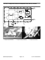
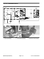
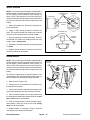
Service Manual
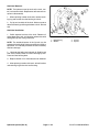
Sand ProR 2020/3020/5020
Preface
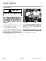
The purpose of this publication is to provide the service
technician with information for troubleshooting, testing,
and repair of major systems and components on the
Sand Pro 2020/3020/5020.
REFER TO THE OPERATOR’S MANUALS FOR OPERATING, MAINTENANCE AND ADJUSTMENT
INSTRUCTIONS. Space is provided in Chapter 2 of this
book to insert the Operator’s Manuals and Parts Catalogs for your machine. Replacement Operator’s Manuals are available by sending complete Model and Serial
Number to:
The Toro Company
8111 Lyndale Avenue South
Bloomington, MN 55420–1196
The Toro Company reserves the right to change product
specifications or this publication without notice.
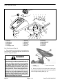
This safety symbol means DANGER, WARNING,
or CAUTION, PERSONAL SAFETY INSTRUCTION. When you see this symbol, carefully read
the instructions that follow. Failure to obey the
instructions may result in personal injury.
NOTE: A NOTE will give general information about the
correct operation, maintenance, service, testing, or repair of the machine.
IMPORTANT: The IMPORTANT notice will give important instructions which must be followed to prevent damage to systems or components on the
machine.
E The Toro Company – 1998, 2003, 2006
Sand Pro 2020/3020/5020
Safety Instructions . . . . . . . . . . . . . . . . . . . . . . . . . . 1 – 1
Jacking Instructions . . . . . . . . . . . . . . . . . . . . . . . . . 1 – 4
Safety and Instruction Decals . . . . . . . . . . . . . . . . 1 – 5
Specifications . . . . . . . . . . . . . . . . . . . . . . . . . . . . . . 4 – 2
General Information . . . . . . . . . . . . . . . . . . . . . . . . 4 – 3
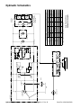
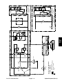
Hydraulic Schematics . . . . . . . . . . . . . . . . . . . . . . . 4 – 6
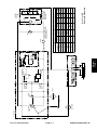
Hydraulic Flow Diagrams . . . . . . . . . . . . . . . . . . . . 4 – 8
Special Tools . . . . . . . . . . . . . . . . . . . . . . . . . . . . . 4 – 14
Trouble Shooting . . . . . . . . . . . . . . . . . . . . . . . . . . 4 – 16
Testing . . . . . . . . . . . . . . . . . . . . . . . . . . . . . . . . . . . 4 – 19
Adjustments . . . . . . . . . . . . . . . . . . . . . . . . . . . . . . 4 – 28
Service and Repairs . . . . . . . . . . . . . . . . . . . . . . . 4 – 31
Product Records . . . . . . . . . . . . . . . . . . . . . . . . . . .
Equivalents and Conversions . . . . . . . . . . . . . . . .
Torque Specifications . . . . . . . . . . . . . . . . . . . . . . .
Lubrication . . . . . . . . . . . . . . . . . . . . . . . . . . . . . . . .
Operation and Service History Reports . . . . . . . .
2–1
2–2
2–3
2–4
2–7
Chapter 3 – Engine
Introduction . . . . . . . . . . . . . . . . . . . . . . . . . . . . . . . . 3 – 2
Specifications . . . . . . . . . . . . . . . . . . . . . . . . . . . . . . 3 – 3
General Information . . . . . . . . . . . . . . . . . . . . . . . . 3 – 4
Adjustments . . . . . . . . . . . . . . . . . . . . . . . . . . . . . . . 3 – 7
Service and Repairs . . . . . . . . . . . . . . . . . . . . . . . . 3 – 8
Briggs & Stratton Vanguard Service and Repair Manual
for 4–Cycle V–Twin Cylinder OHV Engines
Chapter 5 – Electrical Systems
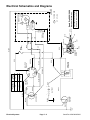
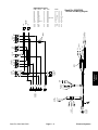
Electrical Schematics and Diagrams . . . . . . . . . . 5 – 2
Special Tools . . . . . . . . . . . . . . . . . . . . . . . . . . . . . . 5 – 6
Troubleshooting . . . . . . . . . . . . . . . . . . . . . . . . . . . . 5 – 7
Electrical System Quick Checks . . . . . . . . . . . . . . 5 – 9
Component Testing . . . . . . . . . . . . . . . . . . . . . . . . 5 – 10
Service and Repairs . . . . . . . . . . . . . . . . . . . . . . . 5 – 13
Chapter 6 – Wheels, Brakes, and Miscellaneous
Wheels, Brakes
and Miscellaneous
Electrical
Systems
Specifications . . . . . . . . . . . . . . . . . . . . . . . . . . . . . . 6 – 2
Adjustments . . . . . . . . . . . . . . . . . . . . . . . . . . . . . . . 6 – 3
Service and Repairs . . . . . . . . . . . . . . . . . . . . . . . . 6 – 5
Hydraulic
Systems
Chapter 2 – Product Records and Manuals
Product Records
and Manuals
Chapter 4 – Hydraulic Systems
Engine
Chapter 1 – Safety
Safety
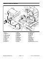
Table Of Contents
Sandpro 2020/3020/5020
Sand Pro 2020/3020/5020
Chapter 1
Safety
Safety
Table of Contents
GENERAL SAFETY INSTRUCTIONS . . . . . . . . . . . .
Before Operating . . . . . . . . . . . . . . . . . . . . . . . . . . . .
While Operating . . . . . . . . . . . . . . . . . . . . . . . . . . . .
Maintenance and Service . . . . . . . . . . . . . . . . . . . .
1
1
2
3
JACKING INSTRUCTIONS . . . . . . . . . . . . . . . . . . . . .
SAFETY AND INSTRUCTION DECALS . . . . . . . . . .
Sand Pro 2020/3020 . . . . . . . . . . . . . . . . . . . . . . . .
Sand Pro 5020 . . . . . . . . . . . . . . . . . . . . . . . . . . . . .
4
5
5
6
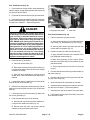
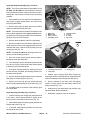
General Safety Instructions
The Sand Pro 2020/3020/5020 were tested and certified
by TORO for compliance with the B71.4–1984 specifications of the American National Standards Institute. Although hazard control and accident prevention partially
are dependent upon the design and configuration of the
machine, these factors are also dependent upon the
awareness, concern, and proper training of the personnel involved in the operation, transport, maintenance,
and storage of the machine. Improper use or maintenance of the machine can result in injury or death.
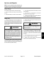
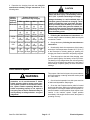
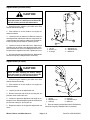
WARNING
To reduce the potential for injury or death,
comply with the following safety instructions.
Before Operating
1. Operate machine only after reading and understanding the contents of this manual. A replacement
manual is available by sending complete model and serial number to:
7. Ensure traction interlock switch is adjusted correctly
so engine cannot be started unless traction pedal is released and in neutral position.
8. Keep everyone, especially children and pets away
from the areas of operation.
The Toro Company
8111 Lyndale Avenue South
Minneapolis, Minnesota 55420–1196
9. Gasoline is highly flammable; handle it carefully.
2. Never allow children to operate the machine or
adults to operate it without proper instructions.
A. Use an approved gasoline container.
B. Do not remove cap from fuel tank when engine is
hot or running.
3. Become familiar with the controls and know how to
stop the engine quickly.
C. Do not smoke while handling gasoline.
4. Keep all shields, safety devices and decals in place.
If a shield, safety device or decal is malfunctioning, illegible, or damaged, repair or replace it before operating
the machine.
D. Fill fuel tank outdoors to about one inch below
top of tank, (bottom of filler neck). Do not overfill.
E. Wipe up any spilled gasoline.
5. Always wear substantial shoes. Do not operate machine while wearing sandals, tennis shoes or sneakers.
Do not wear loose fitting clothing which could get caught
in moving parts and cause personal injury.
6. Wearing safety glasses, safety shoes, long pants
and a helmet is advisable and required by some local
safety and insurance regulations.
Sand Pro 2020/3020/5020
10. Check the safety interlock system daily for proper
operation (see Check Interlock System in Chapter 5 –
Electrical Systems). If the switch should malfunction, replace switch before operating machine. (After every two
years, replace interlock switch in the safety system,
whether it is working properly or not.)
Page 1 – 1
Safety
While Operating
11. Exhaust fumes are hazardous and could be deadly,
so do not run the engine in a confined area without adequate ventilation.
15. If optional Draw Bar (Part No. 92–2330) or Hitch Kit
(Model No. 08833) is installed on machine, vertical load
on hitch should not exceed 200 lbs.
12. Sit on seat when operating the machine. Never
carry passengers.
16. Do not touch engine, muffler or exhaust pipe while
engine is running or soon after it has stopped because
these areas are hot enough to cause burns.
13. When starting the engine:
A. Make sure traction pedal is released.
B. After the engine is started, keep foot off traction
pedal. Machine must not move. If movement is evident, the neutral return mechanism is adjusted incorrectly; therefore, shut engine off and readjust
mechanism so machine does not move when in
neutral position. If engine does not start, check interlock switch connections.
17. If the machine ever vibrates abnormally, stop immediately, turn engine off, wait for all motion to stop and
inspect for damage. Repair all damage before commencing operation.
18. Before getting off the seat:
A. Stop movement of the machine.
B. Set parking brake and lower attachments to the
ground. Take precautions to prevent accidental
starts, rolling away, etc.
14. Using the machine demands attention. To prevent
tipping or loss of control:
A. Use care when entering and leaving sand traps.
Use extreme caution around ditches, creeks or other hazards.
19. Whenever machine is left unattended, be sure engine is stopped, parking brake is set, attachments are
lowered to the ground, and key is removed from ignition.
B. Watch for holes or other hidden hazards.
C. Use caution when operating machine on a steep
slope. Reduce speed when making sharp turns or
when turning on hillsides.
D. Avoid sudden stops and starts. Do not go from
reverse to full forward without first coming to a complete stop.
E. Before backing up, look to the rear and assure
no one is behind the machine.
F. Watch out for traffic when near of crossing roads.
Always yield the right of way.
Safety
Page 1 – 2
Sand Pro 2020/3020/5020
20. Before servicing or making adjustments to the machine, stop engine, remove key from the ignition, and
pull the spark plug wire off spark plug to prevent accidental starting of the engine.
27. If the engine must be running to perform a maintenance adjustment, keep hands, feet, clothing, and any
parts of the body away from the engine and any moving
parts. Keep everyone away.
21. Make sure all hydraulic line connectors are tight,and
all hydraulic hoses and lines are in good condition before applying pressure to the system.
28. Do not overspeed engine by changing governor settings. Maximum engine speed is 3200 rpm. To assure
safety and accuracy, have an Authorized Toro Distributor check maximum engine speed with a tachometer.
22. Keep body and hands away from pin hole leaks or
nozzles that eject hydraulic fluid under high pressure.
Use paper or cardboard, not hands, to search for leaks.
Hydraulic fluid escaping under pressure can have sufficient force to penetrate skin and do serious damage. If
fluid is injected into the skin it must be surgically removed within a few hours by a doctor familiar with this
form of injury or gangrene may result.
23. Before disconnecting or performing any work on the
hydraulic system, all pressure in system must be relieved by stopping engine, engaging parking brake and
lowering attachments to the ground.
24. To make sure entire machine is in good condition,
keep all nuts, bolts and screws properly tightened.
25. If major repairs are ever needed or assistance is required, contact an Authorized TORO Distributor.
26. To reduce potential fire hazard, keep the engine
area free of excessive grease, grass, leaves and accumulation of dirt.
Sand Pro 2020/3020/5020
29. Engine must be shut off before checking oil or adding oil to the crankcase.
30. To be sure of optimum performance and safety, always purchase genuine TORO replacement parts and
accessories. Replacement parts and accessories made
by other manufacturers could be dangerous. Such use
could void the product warranty of The Toro Company.
31. When changing attachments, tires, or performing
other service, use correct blocks, hoists, and jacks.
Make sure machine is parked on a solid level floor such
as a concrete floor. Prior to raising the machine, remove
any attachments that may interfere with the safe and
proper raising of the machine. Always chock or block
wheels. Used jack stands or solid wood blocks to support the raised machine. If the machine is not properly
supported by blocks or jack stands, the machine may
move or fall, which may result in personal injury.
Page 1 – 3
Safety
Safety
Maintenance and Service
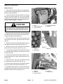
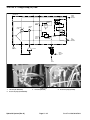
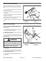
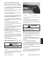
Jacking Instructions
CAUTION
When changing attachments, tires, or performing other service, use correct blocks,
hoists, and jacks. Make sure machine is
parked on a solid level floor such as a concrete
floor. Prior to raising the machine, remove any
attachments that may interfere with the safe
and proper raising of the machine. Always
chock or block wheels. Used jack stands or
solid wood blocks to support the raised machine. If the machine is not properly supported
by blocks or jack stands, the machine may
move or fall, which may result in personal injury.
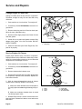
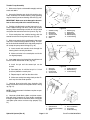
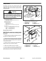
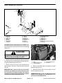
Figure 1
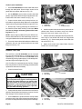
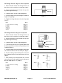
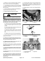
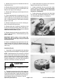
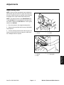
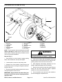
Use the following positions when jacking up the machine:
Jacking the Front End
1. On the SP 2020/3020, jack from below the front
cross support that is above the retaining strip for the rubber shield (Fig. 1).
2. On the SP 5020, jack from below the front cross
support tube on the bottom of the frame (Fig. 2).
Figure 2
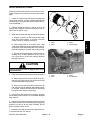
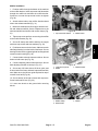
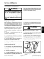
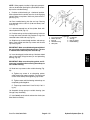
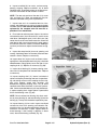
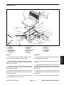
Jacking the Rear End
1. On the SP 2020/3020, jack from below the square
tube of the frame (Fig. 3).
2. On the SP 5020, jack from below the square tube of
the frame (Fig. 3).
Figure 3
Figure 4
Safety
Page 1 – 4
Sand Pro 2020/3020/5020
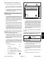
Safety and Instruction Decals
Safety
The following safety and instruction decals are installed on the Sand Pro 2020/3020. If any become damaged
or illegible, replace them. Decal part numbers are listed below and in the parts catalog. Order replacements
from your Authorized Toro Distributor.
93–9051
ON NEUTRAL ADJUST
MECHANISM
(Part No. 93–9051)
UNDER SEAT PLATE
(Part No. 95–0646)
ON VALVE SHROUD
(Part No. 95–0647)
ON ENGINE SHIELD
(Part No. 92–8985)
ON ENGINE SHIELD
(Part No. 95–0645)
ON DASH PANEL
(Part No. 95–0648)
Sand Pro 2020/3020/5020
Page 1 – 5
Safety
Safety and Instruction Decals
The following safety and instruction decals are installed on the Sand Pro 5020. If any become damaged or
illegible, replace them. Decal part numbers are listed below and in the parts catalog. Order replacements from
your Authorized Toro Distributor.
ON BOTH SIDES OF FAN SHROUD (2)
(Part No. 93–7272)
ON NEUTRAL ADJUST
MECHANISM
(Part No. 93–9051)
ON MUFFLER SHIELD
(Part No. 95–0645)
ON RIGHT FENDER
(Part No. 98–0975)
UNDER SEAT PLATE
(Part No. 98–0977)
ON FRAME & BOTH SIDES
OF CENTER PANEL (3)
(Part No. 93–9052)
ON LEFT FENDER
(Part No. 93–9053)
ON CENTER PANEL
(Part No. 93–9050)
Safety
ON BATTERY
(Part No. 93–7276)
ON RIGHT FENDER
(Part No. 93–7442)
Page 1 – 6
UNDER BATTERY
(Part No. 93–6668)
Sand Pro 2020/3020/5020
Chapter 2
Product Records and Maintenance
PRODUCT RECORDS . . . . . . . . . . . . . . . . . . . . . . . . .
EQUIVALENTS AND CONVERSIONS . . . . . . . . . . .
Decimal and Millimeter Equivalents . . . . . . . . . . . .
U.S. to Metric Conversions . . . . . . . . . . . . . . . . . . .
1
2
2
2
TORQUE SPECIFICATIONS . . . . . . . . . . . . . . . . . . .
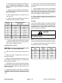
Capscrew Markings and Torque Values – U.S. . .
Capscrew Markings and Torque Values – Metric
LUBRICATION . . . . . . . . . . . . . . . . . . . . . . . . . . . . . . . .
OPERATION & SERVICE HISTORY REPORTS . . .
3
3
3
4
7
Product Records
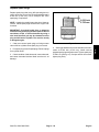
Record maintenance and repair information about your
Sand Pro 2020/3020/5020 on the OPERATION AND
SERVICE HISTORY REPORT form. Use this information when referring to your machine.
Sand Pro 2020/3020/5020
Insert Operator’s Manuals and Parts Catalogs for your
Sand Pro 2020/3020/5020 at the end of this section.
Page 2 – 1
Product Records and Maintenance
Product Records
and Maintenance
Table of Contents
Equivalents and Conversions
Product Records and Maintenance
Page 2 – 2
Sand Pro 2020/3020/5020
Product Records
and Maintenance
Torque Specifications
Sand Pro 2020/3020/5020
Page 2 – 3
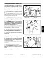
Product Records and Maintenance
Lubrication
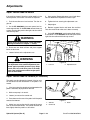
CAUTION
Before servicing or making adjustments to the
machine, stop engine, set parking brake, and remove key from the ignition switch.
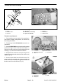
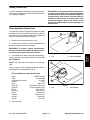
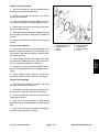
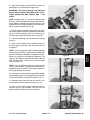
Lubricate grease fittings regularly with No. 2 general
purpose lithium base grease. Lubricate front wheel
bearing and traction control linkage every 25 hours of
operation. Lubricate steering shaft and steering shaft
sprocket every 100 hours.
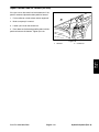
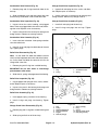
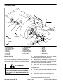
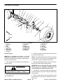
Figure 1
Sand Pro 2020/3020 (Early Models)
The three fittings that must be lubricated are: front
wheel bearing (Fig. 1), traction control linkage (Fig. 3)
and steering shaft (Fig. 4).
Sand Pro 2020/3020 (Late Models)
The four fittings to lubricated are: front wheel bearing
(Fig. 1), traction control linkage (Fig. 3) and steering
shaft and steering chain sprocket shaft(Fig. 5).
Sand Pro 5020
The four fittings to lubricate are: front wheel bearing
(Fig. 2), traction control linkage (Fig. 3), and both the
steering shaft and steering chain sprocket shaft (Fig. 6).
Figure 2
NOTE: On the Sand Pro 5020, gain access to the
grease fitting on the traction control linkage (Fig. 3) by
removing the right side panel.
1. Wipe grease fitting clean so foreign matter cannot
be forced into the bearing or bushing.
2. Pump grease into the bearing or bushing. Wipe up
excess grease.
NOTE: Do not lubricate steering chain unless it becomes stiff from rust. If the chain rusts, it may be lubricated lightly with a dry type lubricant.
Figure 3
Figure 4
Product Records and Maintenance
Page 2 – 4
Sand Pro 2020/3020/5020
Sand Pro 2020/3020/5020
Figure 6
Page 2 – 5
Product Records and Maintenance
Product Records
and Maintenance
Figure 5
Product Records and Maintenance
Page 2 – 6
Sand Pro 2020/3020/5020
Product Records
and Maintenance
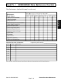
EQUIPMENT OPERATION AND SERVICE HISTORY REPORT
for
Sand ProR 2020/3020/5020
TORO Model and Serial Number: _____________–___________
Engine Numbers:
_________________________
Transmission Numbers:
_________________________
Date Purchased:
_________________________
Purchased From:
_________________________
Warranty Expires___________
_________________________
_________________________
Contacts:
Parts
_________________________
Phone___________________
Service
_________________________
Phone___________________
Sales
_________________________
Phone___________________
See your TORO Distributor for other Publications, Manuals, and Videos from the TORO company.
Sand Pro 2020/3020/5020
Page 2 – 7
Product Records and Maintenance
Sand Pro R
2020/3020/5020
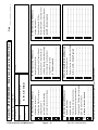
Maintenance Schedule
Minimum Recommended Maintenance Intervals:
Maintenance Procedure
Maintenance Interval & Service
Every
25hrs
Check Battery Fluid Level
Check Battery Cable Connections
{ Change Engine Oil
Lubricate Front Wheel Bearing
Every
100hrs
Every
400hrs
Every
800hrs
A–Level
Service
Lubricate Traction Control LInkage
Replace Engine Oil Filter
Inspect Remote Air Cleaner Element
Inspect Engine Air Cleaner Element
Lubricate Steering Shaft Grease Fitting
Check Steering Chain Adjustment
B–Level
Service
{ Torque Wheel Lug Nuts
Change Hydraulic Oil
{ Replace Hydraulic Oil Filter
Replace Remote Air Cleaner Element
Replace Engine Air Cleaner Element
C–Level
Service
Replace Spark Plugs
Replace Fuel Filter
Decarbonize Combustion Chamber
Adjust Valves and Torque Head Bolts
Check Engine RPM (idle and full throttle)
Drain and Clean Fuel Tank
D–Level
Service
{ Initial break in at 8 hours
Replace Moving Hoses
Replace Traction Interlock (Safety) Switch
Annual Recommendations:
Items listed are recommended every 1,500 hours
or 2 years, whichever comes first.
(See proper section of Operator’s and Service Manuals for procedures and fluid specifications.)
Product Records and Maintenance
Page 2 – 8
Sand Pro 2020/3020/5020
Sand Pro R
2020/3020/5020 Daily Maintenance Checklist
Daily Maintenance: (duplicate this page for routine use)
Daily Maintenance Check For Week Of ____________
MON
n
Safety Interlock Operation
n
Steering Operation
n
Engine Oil Level
n
Remote/Engine Air Cleaner Condition
TUES
WED
THURS
FRI
SAT
SUN
Product Records
and Maintenance
Maintenance
Check Item b
Clean Engine Cooling Fins
n
Unusual Engine Noises
n
Unusual Operating Noises
n
Hydraulic System Oil Level
n
Hydraulic Hoses for Damage
n
Fluid Leaks
n
Fuel Level
n
Tire Pressure
n
Instrument Operation
Touch–up Damaged Paint
Notation for areas of concern:
Item
Date
Inspection performed by:__________________
Information
1
2
3
4
5
6
7
8
(Check proper section of Operator’s and Service Manuals for procedures and fluid specifications.)
Sand Pro 2020/3020/5020
Page 2 – 9
Product Records and Maintenance
Product Records and Maintenance
Page 2 – 10
Sand Pro 2020/3020/5020
R
2020/3020/5020
A B C D Other
Service to perform (circle):
A – Service required
_______________________________
_______________________________
________________________________
________________________________
________________________________
_______________________________
_______________________________
_______________________________
_______________________________
A, B, C, and D – Service Required
_______________________________
_______________________________
_______________________________
_______________________________
_______________________________
_______________________________
Decarbonize Combustion Chamber
Adjust Valves and Torque Head Bolts
Check Engine RPM (idle and full throttle)
Drain and Clean Fuel Tank
A, B, and C – Sevice required
________________________________
________________________________
(See Operator’s and Service Manual for specifications and procedures.)
_______________________________
Replace Traction Interlock (Safety) Switch
Replace Fuel Filter
_______________________________
_______________________________
_______________________________
_______________________________
Replace Moving Hoses
_______________________________
_______________________________
_______________________________
_______________________________
A and B – Sevice required
Replace Engine Air Cleaner Element
Replace Remote Air Cleaner Element
Replace Hydraulic Oil Filter
Change Hydraulic Oil
C – Service (every 400 hours)
Date: ________________
Replace Spark Plugs
Other – Annual Service and Specials
Torque Wheel Lug Nuts
________________________________
D – Service (every 800 houurs)
Check Steering Chain Adjustment
Lubricate Traction Control Linkage
Inspect Engine Air Cleaner Element
Change Engine Oil
Lubricate Steering Shaft Grease Fitting
Inspect Remote Air Cleaner Element
Check Battery Cable Connections
Lubricate Front Wheel Bearing
Replace Engine Oil Filter
Check Battery Fluid Level
B – Service (every 100 hours)
Remarks:
Maintenance Supervisor Work Order
__________________–__________________
TORO I.D. #:
A– Service (every 25 hours)
Technician:
Hours:
Unit Designation:
(Duplicate this page for routine use.)
Sand Pro
Chapter 3
Engine
INTRODUCTION . . . . . . . . . . . . . . . . . . . . . . . . . . . . . . 2
SPECIFICATIONS . . . . . . . . . . . . . . . . . . . . . . . . . . . . 3
GENERAL INFORMATION . . . . . . . . . . . . . . . . . . . . . 4
Check Engine Oil . . . . . . . . . . . . . . . . . . . . . . . . . . . 4
Fuel Shutoff Valve . . . . . . . . . . . . . . . . . . . . . . . . . . . 5
Fill Fuel Tank . . . . . . . . . . . . . . . . . . . . . . . . . . . . . . . 6
ADJUSTMENTS . . . . . . . . . . . . . . . . . . . . . . . . . . . . . . 7
Adjust Throttle Control . . . . . . . . . . . . . . . . . . . . . . . 7
Adjust Choke Control . . . . . . . . . . . . . . . . . . . . . . . . 7
SERVICE AND REPAIRS . . . . . . . . . . . . . . . . . . . . . . 8
Change Engine Oil and Filter . . . . . . . . . . . . . . . . . 8
Service Engine Air Cleaner . . . . . . . . . . . . . . . . . . . 8
Service Remote Air Cleaner . . . . . . . . . . . . . . . . . . 9
Throttle and Choke Controls . . . . . . . . . . . . . . . . . 10
Throttle Control Removal . . . . . . . . . . . . . . . . . . 10
Throttle Control Installation . . . . . . . . . . . . . . . . . 11
Choke Control Removal . . . . . . . . . . . . . . . . . . . . 11
Choke Control Installation . . . . . . . . . . . . . . . . . 12
Replace Fuel Filter . . . . . . . . . . . . . . . . . . . . . . . . . 12
Remote Air Cleaner (SP 2020/3020) . . . . . . . . . . 13
Remote Air Cleaner (SP 5020) . . . . . . . . . . . . . . . 14
Sand Pro 2020/3020/5020
Muffler (SP 5020) . . . . . . . . . . . . . . . . . . . . . . . . . . 15
Muffler (SP 2020/3020) . . . . . . . . . . . . . . . . . . . . . 16
Muffler Removal . . . . . . . . . . . . . . . . . . . . . . . . . . 16
Muffler Installation . . . . . . . . . . . . . . . . . . . . . . . . 17
Fuel Tank (SP 2020/3020) . . . . . . . . . . . . . . . . . . . 18
Fuel Tank Removal . . . . . . . . . . . . . . . . . . . . . . . 19
Fuel Tank Installation . . . . . . . . . . . . . . . . . . . . . . 19
Fuel Tank (SP 5020) . . . . . . . . . . . . . . . . . . . . . . . . 20
Fuel Tank Removal . . . . . . . . . . . . . . . . . . . . . . . 20
Fuel Tank Installation . . . . . . . . . . . . . . . . . . . . . . 21
Engine (SP 2020/3020) . . . . . . . . . . . . . . . . . . . . . 22
Engine Removal . . . . . . . . . . . . . . . . . . . . . . . . . . 23
Engine Installation . . . . . . . . . . . . . . . . . . . . . . . . 24
Replace Spark Plugs . . . . . . . . . . . . . . . . . . . . . . . 25
Engine (SP 5020) . . . . . . . . . . . . . . . . . . . . . . . . . . 26
Engine Removal . . . . . . . . . . . . . . . . . . . . . . . . . . 27
Engine Installation . . . . . . . . . . . . . . . . . . . . . . . . 28
Clean Cylinder Head Fins . . . . . . . . . . . . . . . . . . . 30
BRIGGS & STRATTON VANGUARD SERVICE AND
REPAIR MANUAL FOR 4–CYCLE V–TWIN CYLINDER OHV ENGINES
Page 3 – 1
Engine
Engine
Table of Contents
Introduction
This Chapter gives information about specifications,
maintenance, troubleshooting, testing, and repair of the
gasoline engines used in the Sand Pro 2020, 3020, and
5020.
equipment is explained. However, the cost of the test
equipment and the specialized nature of some repairs
may dictate that the work be done at an engine repair facility.
Most repairs and adjustments require tools which are
commonly available in many service shops. Special
tools are described in the Briggs and Stratton Vanguard
Repair and Service Manual for 4–Cycle V–Twin Cylinder OHV Engines. The use of some specialized test
Service and repair parts for Briggs and Stratton Vanguard engines are supplied through your local Briggs
and Stratton dealer or distributor. If no parts list is available, be sure to provide your distributor with the Toro
model and serial number.
Engine
Page 3 – 2
Sand Pro 2020/3020/5020
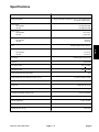
Specifications
Item
Description
Make / Designation
Briggs and Stratton Vanguard, 4–Cycle, V–Twin Cylinder, OHV,
Air Cooled, Gasoline Engine
Horse Power
SP 2020/3020
SP 5020
16 HP @ 3600 RPM
18 HP @ 3600 RPM
Bore mm (in.)
SP 2020/3020
SP 5020
68.0 (2.677)
71.98 (2.834)
Total Displacement cc (cu. in.)
SP 2020/3020
SP 5020
480 (29.3)
570 (34.8)
Unleaded Regular Grade Gasoline
Fuel Capacity liters (gallons)
SP 2020/3020
SP 5020
16.1 (4.25)
20.8 (5.50)
Fuel Pump
Pulsating Crankcase Vacuum
Governor
Mechanical
Low Idle (no load)
1750 + 50 RPM
High Idle (no load)
3150 + 50 RPM
Intake and Exhaust Valve Seat Angle
45_
Intake and Exhaust Valve Clearance (Cold) mm (in.)
0.10 to 0.15 (0.004 to 0.006)
Carburetor
Single Barrel, Float Feed with Suppress Afterfire Solenoid
Engine Oil
SAE 30 SE, SF, or SG
Oil Pump
Internal Gear Driven Gerotor Type
Crankcase Oil Capacity liters (U.S. qt.)
1.66 (1.75) with filter
Starter
12 VDC
Alternator/Regulator
12 VDC 16 AMP
Spark Plug
Champion RC12YC or NGK BKR4E or Equivalent
Spark Plug Gap mm (in.)
Sand Pro 2020/3020/5020
0.76 (0.030)
Page 3 – 3
Engine
Engine
Fuel
General Information
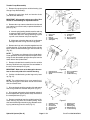
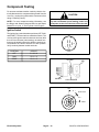
Check Engine Oil
2
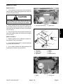
CAUTION
Before servicing or making adjustments to the
machine, make sure of the following: stop engine, engage parking brake, lower attachment,
and remove key from the switch.
IMPORTANT: Check oil level every 8 operating
hours or daily. Change oil initially after the first 8
hours of operation. Thereafter, change oil every 25
hours and filter every 100 hours under normal conditions. Change oil more frequently when the engine is operated in extremely dusty or dirty
conditions.
The engine is shipped with 1–3/4 quarts (w/ filter) of oil
in the crankcase; however, oil level must be checked before and after the engine is first started.
1. Position machine on a level surface.
2. Unscrew dipstick and wipe it with a clean rag. Screw
dipstick into the tube, and make sure it is seated fully.
Unscrew dipstick out of the tube. Check oil level. If oil
level is low, remove filler cap from the valve cover (next
to dipstick), and add enough oil to raise the level to the
FULL mark on the dipstick.
Engine
1
Figure 1
1. Dipstick
2. Filler cap
3. The engine uses any high-quality detergent oil having the American Petroleum Institute -API- “service classification” SE, SF or SG. Recommended viscosity
(weight) is SAE 30.
IMPORTANT: Dipstick must be fully seated in tube
to provide proper sealing of engine crankcase. Failure to seal crankcase may result in engine damage.
4. Install dipstick firmly into the tube.
Page 3 – 4
Sand Pro 2020/3020/5020
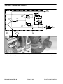
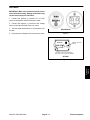
Fuel Shutoff Valve
This valve should be shut when removing the engine or
placing the unit in long term storage.
1
On the SP 2020/3020, the shutoff valve can be accessed from the rear of the machine (Fig. 2).
On the SP 5020, the shutoff valve can be accessed by
removing the left side panel (Fig. 3).
2
Figure 2
2. Hydraulic oil filter
Engine
1. Fuel shutoff valve
1
2
Figure 3
1. Fuel shutoff valve
Sand Pro 2020/3020/5020
Page 3 – 5
2. Hydraulic oil tank
Engine
Fill Fuel Tank
IMPORTANT: The Toro Company strongly recommends using fresh, clean, unleaded regular grade
gasoline in Toro gasoline powered products. Unleaded gasoline burns cleaner, extends engine life,
and promotes good starting by reducing the build–
up of combustion chamber deposits. Leaded gasoline can be used if unleaded is not available.
IMPORTANT: Never use methanol, gasoline containing methanol, gasoline containing more than
10% ethanol, gasoline additives, premium gasoline,
or white gas. Damage may result to engine fuel system.
NOTE: Fuel tank capacity is about 4.25 gallons for the
SP 2020/3020 and 5.5 gallons for the SP 5020.
1. Clean area around fuel tank cap.
2. Remove fuel tank cap.
3. Fill tank about one inch below top of the tank, (bottom of filler neck). DO NOT OVERFILL. Then install cap.
4. Prevent a fire hazard. Wipe up any spilled fuel.
Engine
DANGER
Gasoline is flammable; use caution when storing
or handling it. Do not fill fuel tank while the engine is running, hot, or when machine is in an enclosed area. Vapors may build up, and can be ignited by a spark or flame source many feet away.
Prevent the possibility of an explosion. DO NOT
SMOKE while filling the fuel tank. Always fill fuel
tank outside. Wipe up any spilled gasoline before
starting the engine. Use a funnel or spout to prevent spilling gasoline. Fill tank no higher than
one inch below top of tank, (bottom of filler neck).
DO NOT OVER FILL. Store gasoline in a clean
safety approved container and keep the cap on
the container. Keep gasoline in a cool, well–ventilated place; never store in an enclosed area
such as a hot storage shed. To assure volatility,
do not buy more than a 30 day supply of gasoline.
Gasoline is a fuel for internal combustion engines; do not use it for any other purpose. Many
children like the smell of gas, so keep it out of
their reach. Gas fumes are explosive and dangerous to inhale.
Page 3 – 6
Sand Pro 2020/3020/5020
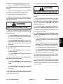
Adjustments
Adjust Throttle Control
1. Pivot seat up. On the SP 2020/3020, remove the engine shield.
4
5
1
3
6
2. Loosen cable clamp screw securing the cable to the
engine.
3. Move remote throttle control lever forward to the
FAST position.
4. Pull firmly on the throttle cable until the back of
throttle swivel contacts the throttle stop.
5. Tighten cable clamp screw. Check engine idle setting.
2
Figure 4
1. Cable clamp screw
2. Throttle cable
3. Throttle swivel
4. Throttle stop
5. Cable clamp screw
6. Choke cable
A. High Idle: 3150 50
B. Low Idle: 1750 50
Adjust Choke Control
1. Pivot seat up. On the SP 2020/3020, remove the engine shield.
4
1
2. Remove air cleaner cover, cover plate, and air
cleaner filter element from the air cleaner base (See
Service Engine Air Cleaner).
3. Loosen cable clamp screw securing the choke
cable to engine (Fig. 4).
2
3
4. Pull choke control knob out completely from dash
panel (SP 2020/3020). Shift choke lever to the choke
position (SP 5020).
NOTE: Newer engine models will have a different car-
buretor shield that has five hex head flange screws securing the shield and air cleaner base to the carburetor.
Figure 5
1. Carburetor shield
2. Air cleaner base
3. Choke butterfly
4. Carburetor shield (newer
models)
5. Pull firmly on the choke cable until the choke butterfly is completely closed. Make sure choke control knob
is still pulled out completely or the choke lever is shifted
to choke, then tighten cable clamp screw (Fig. 4).
6. Reinstall air cleaner filter element, cover plate, and
air cleaner cover to the air cleaner base (See Service
Engine Air Cleaner).
Sand Pro 2020/3020/5020
Page 3 – 7
Engine
Engine
Proper throttle operation is dependent upon the proper
adjustment of the throttle control. Before adjusting the
carburetor, assure throttle control is operating properly.
Service and Repairs
Change Engine Oil and Filter
Change oil initially after the first 8 hours of operation.
Thereafter, change oil every 25 hours and filter every
100 hours.
1. Park machine on a level surface. Turn engine off.
2. Pivot seat up. On the SP 2020/3020, remove the engine shield.
3. Remove drain plug and let oil flow into drain pan.
When oil stops, install drain plug.
4. Remove oil filter. Apply a light coat of clean oil to the
new filter gasket.
1
2
5. Screw filter on by hand until gasket contacts filter
adapter, then tighten 1/2 to 3/4 turn further. DO NOT
OVER–TIGHTEN.
Figure 6
1. Drain plug
2. Oil filter
6. Add oil to crankcase (see Check Engine Oil). Dispose of oil properly.
Service Engine Air Cleaner
Inspect paper element every 100 hours of operation.
Replace element every 400 hours or when dirty or damaged. Do not wash paper element or do not clean with
compressed air as damage will occur.
1
1. Park machine on a level surface. Turn engine off.
2
2. Pivot seat up. On the SP 2020/3020, remove the engine shield.
3
4
3. Remove knobs and air cleaner cover.
4. Remove filter element and cover plate. Inspect filter
for cleanliness, ruptures, holes, and tears. Replace defective filter element.
5
5. With air cleaner disassembled, check air cleaner
components for damage. Replace if necessary.
A. Make sure rubber breather tube in base plate is
securely in place or severe engine damage may occur.
6
Figure 7
1. Knob
2. Cover
3. Knob
4. Cover plate
5. Filter element
6. Air cleaner base
B. Make sure carburetor breather hose is routed
out through engine vents.
6. Reinstall filter element. Secure element with cover
plate and knob. Reinstall air cleaner cover and secure
with knobs.
Engine
Page 3 – 8
Sand Pro 2020/3020/5020
Service Remote Air Cleaner
Inspect air cleaner filter element every 100 hours of operation. Replace every 400 hours or when dirty or damaged
1
2
1. Check air cleaner body and body for damage that
could cause possible air leaks. Replace damaged air
cleaner body or cover (see Remote Air Cleaner Removal and Installation).
2. Release latches securing air cleaner cover to air
cleaner body. Separate cover from the body. Clean inside of the air cleaner cover.
ÇÇ
ÇÇ
ÇÇ
3
4
3. Wash filter element with soap and water as follows:
A. Prepare a solution of filter cleaner and water.
Soak filter element about 15 minutes. See filter
cleaner carton for detailed instructions.
1. Latch
2. Cover
3. Body
4. Filter element
Engine
B. After soaking filter for 15 minutes, rinse it with
clear water. Maximum water pressure must not ex
ceed 40 psi to prevent damage to the filter element.
Rinse filter element from clean side to dirty to side.
Figure 8
4
1
C. Dry filter element using warm, flowing air not ex
ceeding 160_F, or allow element to air–dry. Do not
use a light bulb to dry the filter element because
damage may result.
CAUTION
3
Use eye protection such as goggles when using
compressed air.
4. Clean filter element with compressed air as follows:
2
Figure 9
1. Latch
2. Cover
3. Body
4. Air inlet hood
A. Blow compressed air from the inside to the outside of the dry filter element. Do not exceed 100 psi
to prevent damage to the element.
B. Keep air hose nozzle at least 2 inches from the
filter. Move nozzle up and down while rotating the filter element. Inspect for holes and tears by looking
through the filter toward a bright light.
5. Inspect new filter element for shipping damage.
Check sealing end of element. Do not install a damaged
filter element.
6. Insert new filter element properly into the air cleaner
body. Make sure element is sealed properly by applying
pressure to outer rim of filter when installing. Do not
press on flexible center of filter.
7. Reinstall cover and secure latches. Make sure cover is positioned with TOP side up.
Sand Pro 2020/3020/5020
Page 3 – 9
Engine
Throttle and Choke Controls
1
6
4
4
4
9
2
2
3
1
8
1
5
2
7
Figure 10
1. Knob
2. Throttle control
3. Lock nut
4. Cap screw
5. Dash Panel (SP 2020/3020)
6. Right fender (SP 5020)
7. Hex nut
8. Lock Washer
9. Choke control
Throttle Control Removal
1
1. Park machine on a level surface, lower attachment,
stop engine, engage parking brake, and remove key
from the ignition switch.
2. Pivot seat up. On the SP 2020/3020, remove the engine shield.
2
3. On the SP 2020/3020 remove three hex flange head
screws securing the hood to the front shield (Fig. 11).
Remove four cap screws securing the dash panel to the
hood (Fig. 12). Remove hood from the machine.
4. Release throttle cable from clamp securing it to the
engine. Disconnect throttle cable from the swivel on the
engine (Fig. 13).
3
Figure 11
1. Hex flange head screw
2. Hood
3. Front shield
3
5. Remove throttle knob from the throttle control. Remove both lock nuts and cap screws securing the
throttle control to the dash panel or right fender. Remove
throttle control from the machine (Fig. 10).
1
2
1
Figure 12
1. Cap screws
2. Dash panel
Engine
Page 3 – 10
3. Hood
Sand Pro 2020/3020/5020
Throttle Control Installation
3
1. Secure throttle control to the dash panel or right
fender with both cap screws and lock nuts. Install throttle
control knob to the throttle control lever (Fig. 10).
2. Connect throttle cable to the swivel on the engine.
Attach cable to engine with clamp. Make sure not to
tighten cap screw securing clamp and cable to engine
(Fig. 13).
2
3. On the SP 2020/3020, position hood to the dash
panel and front shield. Secure hood to front shield with
three hex flange head screws (Fig. 11). Secure dash
panel to hood with four cap screws (Fig. 12).
1
4
4. Adjust throttle control (see Adjust Throttle Control).
Install cover over the engine.
Figure 13
1. Throttle cable
2. Clamp
1. Park machine on a level surface, lower attachment,
stop engine, engage parking brake, and remove key
from the ignition switch.
3
5
6
3. On the SP 2020/3020 remove three hex flange head
screws securing the hood to the front shield (Fig. 11).
Remove four cap screws securing the dash panel to the
hood (Fig. 12). Remove hood from the machine.
NOTE: Newer engine models will have a different carburetor shield that has five hex head flange screws securing the shield and air cleaner base to the carburetor.
7
8
Figure 14
1.
2.
3.
4.
5. Remove two cap screws and three hex head flange
screws securing air cleaner base to the carburetor. Remove base carefully from carburetor. Make sure not to
damage carburetor gasket. Cover carburetor to prevent
dirt and debris from entering (Fig. 15).
6. Release choke cable from clamp securing it to the
engine. Disconnect choke cable from the choke pivot lever on the engine (Fig. 16).
4
1
2
2. Pivot seat up. On the SP 2020/3020, remove the engine shield.
4. Remove air hose from air cleaner cover. Remove air
cleaner cover. Remove cover plate and air cleaner element from the air cleaner base (Fig. 14).
3. Swivel
4. Air cleaner
Engine
Choke Control Removal
Hose clamp
Air hose
Air cleaner cover
Air cleaner knob
3
5
5.
6.
7.
8.
2
Air cleaner knob
Cover plate
Air cleaner element
Air cleaner base
3
4
1
3
7. On the SP 2020/3020 remove hex nut and lock
washer securing the choke control to the dash panel.
Pull choke control and cable from dash panel (Fig. 10).
8. On the SP 5020, remove choke knob from the
choke control. Remove both lock nuts and cap screws
securing the choke control to the right fender. Remove
choke control from the machine (Fig. 10).
Sand Pro 2020/3020/5020
Figure 15
1. Cap screw
2. Carburetor shield
3. Hex head flange screw
Page 3 – 11
4. Air cleaner base
5. Carburetor shield (newer
models)
Engine
Choke Control Installation
1
1. On the SP 2020/3020 insert choke cable and control
through the dash panel. Secure choke control to the
panel with lock washer and hex nut (Fig. 10).
4
2. On the SP 5020, secure choke control to the dash
panel or right fender with both cap screws and lock nuts.
Install knob to the choke control lever (Fig. 10).
3
3. Connect choke cable to the choke pivot lever. Attach cable to engine with clamp. Make sure not to tighten
cap screw securing clamp and cable to engine (Fig. 16).
4. Remove any covering protecting the carburetor inlet. Install air cleaner base carefully to carburetor. Make
sure not to damage carburetor gasket while installing base (Fig. 15).
NOTE: Newer engine models will have a different carburetor shield that has five hex head flange screws securing the shield and air cleaner base to the carburetor.
5. Secure air cleaner base and carburetor shield to the
carburetor with two cap screws and three hex head
flange screws (Fig. 15).
2
Figure 16
1. Carburetor
2. Choke cable
3. Clamp
4. Choke pivot lever
6. Install air cleaner element and cover plate to the air
cleaner base. Secure air cleaner cover to air cleaner.
Secure air hose to air cleaner cover. (Fig. 14).
7. Position hood to the dash panel and front shield. Secure hood to front shield with three hex flange head
screws (Fig. 11). Secure dash panel to hood with four
cap screws (Fig. 12).
8. Adjust choke control (see Adjust Choke Control).
Install cover over the engine.
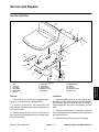
Replace Fuel Filter
The fuel filter on the SP 2020/3020 can be accessed
from the rear of the machine. It is located just left of the
hydrostat (Fig. 17).The fuel filter on the SP 5020 can be
accessed by pivoting up the seat up. It is located just forward and right of the engine (Fig. 18).
1
3
An in–line filter is incorporated into the fuel line. Change
filter every 800 hours. Use the following procedure when
replacement becomes necessary:
1
2
1. Close fuel shutoff valve.
Figure 17
1. Fuel hose
2. Hose clamp
CAUTION
3. Fuel filter
Since gasoline is highly flammable, drain it outdoors and make sure engine is cool to prevent a
potential fire hazard. Wipe up any gasoline that
may have spilled. Do not drain gasoline near any
open flame or where gasoline fumes may be ignited by a spark. Do not smoke a cigar, cigarette,
or a pipe when handling gasoline.
1
3
2. Clamp both fuel hoses connected to the fuel filter so
gasoline cannot drain when hoses are removed. Loosen
hose clamps. Pull fuel hoses off the filter.
3. Secure new filter to hoses with hose clamps. Make
sure arrow on the side of filter points toward the carburetor. Remove clamps that were used to prevent drainage.
Engine
2
2
1
Figure 18
1. Fuel hose
2. Hose clamp
Page 3 – 12
3. Fuel filter
Sand Pro 2020/3020/5020
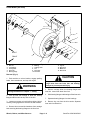
Remote Air Cleaner (SP 2020/3020)
Remote Air Cleaner Removal
1
1. Park machine on a level surface, lower attachment,
stop the engine, engage parking brake, and remove the
key from the ignition switch.
2. Remove three cap screws securing the hood to the
front shield (Fig 19). Remove four cap screws securing
the dash panel to the hood (Fig. 20).
2
3. Loosen hose clamp. Remove air hose from the air
cleaner body (Fig. 21).
5. Unlatch and remove cover from filter body. Separate filter body from the mounting band. Make sure not
to drop the filter element (Fig. 21).
3
Figure 19
1. Hex flange head screw
2. Hood
3. Front shield
Engine
4. Remove both lock nuts, flat washers, and cap
screws securing the mounting band to the front shield
(Fig. 21).
2
Remote Air Cleaner Installation
1
1. Insert filter body through the mounting band. Install
and latch cover to the filter body (Fig. 21).
2. Secure mounting band and air cleaner to the front
shield with both cap screws, flat washers, and lock nuts
(Fig. 21).
2
3. Secure air hose to the air cleaner with hose clamp
(Fig. 21).
4. Position hood to the front shield. Potion dash panel
to the hood. Secure dash panel to the hood with four cap
screws (Fig. 20). Secure hood to the front shield with
three cap screws (Fig 19).
1
Figure 20
1. Cap screws
2. Dash panel
3. Hood
5
1
2
3
4
6
Figure 21
1. Hose clamp
2. Air hose
3. Air cleaner body
Sand Pro 2020/3020/5020
Page 3 – 13
4. Lock nut & flat washer
5. Mounting band
6. Cover
Engine
Remote Air Cleaner (SP 5020)
Remote Air Cleaner Removal
5
1. Park machine on a level surface, lower attachment,
stop the engine, engage parking brake, and remove the
key from the ignition switch.
4
2. Loosen hose clamp. Remove air cleaner hose from
the air cleaner body.
1
3. Remove both lock nuts, flat washers, and cap
screws securing the mounting band to the right fender.
3
4. Unlatch and remove cover from air cleaner body.
Separate body from the mounting band. Make sure not
to drop the filter element.
2
Remote Air Cleaner Installation
Figure 22
1. Body
2. Cap screw & flat washer
3. Mounting band
4. Latch
5. Cover
1. Insert air cleaner body through the mounting band.
Make sure filter element is inside the body. Install and
latch cover to the air cleaner body.
2. Secure mounting band and air cleaner to the front
shield with both cap screws, flat washers, and lock nuts.
3. Secure air hose to the air cleaner with hose clamp.
Engine
Page 3 – 14
Sand Pro 2020/3020/5020
Muffler (SP 5020)
Muffler Removal
1. Park machine on a level surface, lower attachment,
stop the engine, engage parking brake, and remove the
key from the ignition switch.
1
CAUTION
2
The muffler and exhaust pipe may be hot. To
avoid possible burns, allow engine and exhaust
system to cool before working on the muffler.
Figure 23
2. Muffler shield
1
2
3. Remove cap screws securing muffler and both gaskets to the cylinder heads. Pull muffler from the engine
(Fig. 24 and 25).
Engine
2. Access muffler from the rear of the machine. Remove muffler shield from the engine by removing three
cap screws and lock washers securing it to the engine
(Fig. 23 and 24).
1. Cap screw & lock washer
3
4
Muffler Installation
7
1. Replace gaskets if torn or damaged. Replace exhaust detector if worn or damaged.
8
2. Secure gaskets and muffler to cylinder heads with
cap screws (Fig. 24 and 25).
6
5
3. Secure muffler shield to the engine with three cap
screws and lock washers (Fig. 23 and 24).
4
6
Figure 24
1.
2.
3.
4.
Cap screw
Lock washer
Muffler shield
Cap screw
5.
6.
7.
8.
Muffler
Gasket
Screw
Exhaust deflector
2
2
1
Figure 25
1. Muffler
Sand Pro 2020/3020/5020
Page 3 – 15
2. Cylinder head
Engine
Muffler (SP 2020/3020)
Muffler Removal
1
1. Park machine on a level surface, lower attachment,
stop the engine, engage parking brake, and remove the
key from the ignition switch.
4
2. Chock front wheel to prevent machine from moving
with both rear wheels jacked up. Jack up rear wheels
enough to allow the muffler to be removed through the
bottom of the machine. Block up rear wheels (See Jacking Instructions in Chapter 1 – Safety).
CAUTION
2
3
5
Figure 26
The muffler and exhaust pipe may be hot. To
avoid possible burns, allow the engine and exhaust system to cool before working on the muffler.
1. Knob
2. Lock nut & cap screw
3. Lift valve shroud
4. Lift lever guide & latch
5. Cap screw
3. Remove knob from the lift lever. Remove both lock
nuts and cap screws securing the lift valve shroud, lift lever guide, and lift lever latch (Fig. 26).
4. Remove bottom front cap screw securing the lift
valve shroud to the frame. Pull shroud from the frame
(Fig. 26).
3
5. Remove cotter pins from both adjusting rods. Separate adjusting rods from both brake arms (Fig. 27).
1
2
6. Remove cotter pin from the brake rod. Separate
brake rod from the traverse rod lever (Fig. 28).
7. Loosen both hex flange head screws and lock nuts
on each side flange bearing. Lower traverse rod from
the frame (Fig. 28).
Figure 27
1. Cotter pin
2. Adjusting rod
8. Remove three cap screws and star washers securing the muffler shield, R–clamp, and fuel hose to the engine (Fig. 29).
3. Brake arm
5
3
4
9. Remove hex nut, cap screw, flat washer securing
the muffler tab to the muffler bracket (Fig. 30).
1
10. Remove both muffler clamps securing the exhaust
tube to the muffler and exhaust manifold (Fig. 31).
2
11. Separate exhaust tube from the exhaust manifold.
Separate exhaust tube from the muffler. Remove muffler
through the bottom of the machine (Fig. 31).
Figure 28
1. Cotter pin
2. Brake rod
3. Traverse rod lever
Engine
Page 3 – 16
4. Lock nut
5. Flange bearing
Sand Pro 2020/3020/5020
Muffler Installation
1
1. Position muffler through the bottom of the machine
to the muffler bracket. Insert cap screw with flat washer
through the muffler tab and then the muffler bracket.
Screw hex nut onto the cap screw, but do not tighten
(Fig. 30).
2
2. Attach exhaust tube to the muffler. Attach exhaust
tube to the exhaust manifold (Fig. 31).
3. Make sure exhaust tube fits snugly to both the muffler and exhaust manifold. Secure exhaust tube to the
exhaust manifold and muffler with muffler clamps (Fig.
31).
Figure 29
1. Cap screw & star washer
2. Muffler shield
4. Tighten cap screw and hex nut securing the muffler
to the muffler bracket (Fig. 30).
2
5. Secure R–clamp and muffler shield to the engine
with three cap screws and star washers (Fig. 29).
Engine
6. Position traverse rod to the frame. Make sure each
side flange bearing is on the inside of the frame. Secure
bearings to the frame by tightening both hex flange head
screws on each bearing (Fig. 28).
3
7. Connect brake rod to the traverse rod lever. Secure
brake rod with cotter pin (Fig. 28).
1
8. Connect adjusting rods to both brake arms. Secure
both adjusting rods with a cotter pin (Fig. 27).
9. Secure top of lift valve shroud, lift lever guide, and
lift lever latch to the frame with both cap screws and lock
nuts. Make sure nylon lift lever guide is placed on top of
metal lift lever latch (Fig. 26).
Figure 30
1. Lock nut & cap screw
2. Muffler
10. Secure bottom of shroud to frame with cap screw.
Screw knob onto lift lever (Fig. 26).
3. Muffler bracket
3
11. Lower rear wheels to the ground after removing
blocks.
1
1
2
Figure 31
1. Muffler clamps
2. Exhaust tube
Sand Pro 2020/3020/5020
Page 3 – 17
3. Muffler
Engine
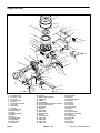
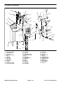
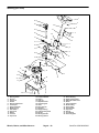
Fuel Tank (SP 2020/3020)
1
2
3
4
26
25
5
24
28
23
22
ANTISEIZE LUBRICANT
30 TO 60 IN–LB
(35 TO 69 KG–CM)
9
8
6
10
27
31
13
7
14
30
11
23
32
21
12
18
15
20
34
19
33
17
16
29
Figure 32
1.
2.
3.
4.
5.
6.
7.
8.
9.
10.
11.
12.
Fuel cap
Fuel tank
Grommet
Fuel tank base
Lock nut
Philips pan head screw
Hose clamp
Fuel hose
Fuel hose clip
Wing nut
Flat washer
Battery clamp
Engine
13.
14.
15.
16.
17.
18.
19.
20.
21.
22.
23.
Cap screw
Flat washer
Battery
Battery bolt
Lock nut
Cap screw
Lock nut
R–clamp
Socket button head screw
Fuel hose
Hose clamp
Page 3 – 18
24.
25.
26.
27.
28.
29.
30.
31.
32.
33.
34.
Fuel shutoff valve
Grommet
Litter box
Battery wire (ground)
Flat washer
Battery decal
Danger decal
Fuel filter
Fuel hose
Terminal boot
Battery wire (start solenoid)
Sand Pro 2020/3020/5020
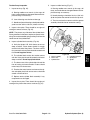
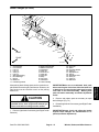
Fuel Tank Removal (Fig. 32)
1
1. Park machine on a level surface, lower attachment,
stop the engine, engage parking brake, and remove the
key from the ignition switch.
2
2. Pivot seat up. Remove litter box (26) from the frame.
3. Disconnect and remove battery from the machine to
prevent possible spillage of fuel on the battery (see Battery Service in Chapter 5 – Electrical Systems).
DANGER
Figure 33
1. Cap screw & lock washer
Fuel Tank installation (Fig. 32)
1. If the fuel tank base (4) was removed,
A. Secure fuel tank base (4) to the frame with three
cap screws (13), flat washers (14), lock nuts (5).
B. Securing filter head to the base with both cap
screws and lock washers (Fig. 33).
2. Position fuel tank (2) to the fuel tank base (4).
A. Apply antiseize lubricant to the threads of the
four philips pan head screws (6).
B. Make sure grommets (3) are in place. Secure
fuel tank to the base with four flat washers (4) and
pan head screws.
4. Drain fuel tank (2) as follows:
A. Close fuel shutoff valve (24).
B. Disconnect fuel hose (22) from the fuel filter (31).
Use funnel and hose to drain the fuel into a suitable
container for storage.
C. Drain fuel tank completely by opening the fuel
shutoff valve. Close fuel shutoff valve when tank is
drained.
5. Loosen hose clamp (7) and disconnect fuel hose (8)
from the bottom of the fuel tank (2).
6. Remove four philips pan head screws (6) and flat
washers (28) securing the fuel tank (2) to the fuel tank
base (4).
7. Lift fuel tank (2) from fuel tank base (4). Make sure
not to lose grommets (3).
C. Torque cap screws from 30 to 60 in–lb (35 to 69
kg–cm).
3. Connect and secure fuel hose (8) to the fuel tank (2)
with hose clamp (7).
4. Connect and secure fuel hose (22) to the fuel filter
(31) with hose clamp (23).
5. Open fuel shutoff valve (9) below the fuel tank.
6. Install and connect battery to the machine (see Battery Service in Chapter 5 – Electrical Systems).
7. Install litter box (26) to the frame. Pivot seat down.
8. Fill fuel tank with fuel (see Fill fuel Tank). Check fuel
lines and tank for leaks.
8. If the fuel tank base (4) is to be removed,
A. Remove both cap screws and lock washers securing the filter head to the base (Fig. 33).
B. Remove three lock nuts, cap screws, and flat
washers securing the base to the frame.
Sand Pro 2020/3020/5020
Page 3 – 19
Engine
Engine
Gasoline is flammable. Use caution when storing
or handling it. Do not drain fuel tank while the engine is running, or when the machine is in an enclosed area. Vapors may build up and be ignited
by a spark or flame source many feet away. DO
NOT SMOKE while draining the fuel tank to prevent the possibility of an explosion. Always drain
fuel tank outside. Wipe up any spilled gasoline.
Store gasoline in a clean, safety–approved container, and secure cap on the container. Keep
gasoline in a cool, well ventilated place and never in an enclosed area such as a hot storage
shed. Since many children like the smell of gas,
keep it out of their reach because the fumes are
explosive and dangerous to inhale.
2. Filter head
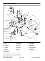
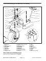
Fuel Tank (SP 5020)
3
4
7
8
9
6
8
10
2
5
1
6
18
16
15
11
17
13
12
11
14 8
7
5
Figure 34
1.
2.
3.
4.
5.
6.
7.
8.
9.
10.
11.
12.
Fuel tank
Fuel cap
Steering boot
Boot retainer
R–clamp
Self tapping screw
13.
14.
15.
16.
17.
18.
Fuel hose
Hose clamp
Fuel filter
Fuel hose
Hose clamp
R–clamp
Fuel hose
Fuel shutoff valve
Whiz cap screw
Cap screw
Flat washer
Grommet
Fuel Tank Removal (Fig. 34)
2
1. Park machine on a level surface, lower attachment,
stop the engine, engage parking brake, and remove the
key from the ignition switch.
3
DANGER
Gasoline is flammable. Use caution when storing
or handling it. Do not drain fuel tank while the engine is running, or when the machine is in an enclosed area. Vapors may build up and be ignited
by a spark or flame source many feet away. DO
NOT SMOKE while draining the fuel tank to prevent the possibility of an explosion. Always drain
fuel tank outside. Wipe up any spilled gasoline.
Store gasoline in a clean, safety–approved container, and secure cap on the container. Keep
gasoline in a cool, well ventilated place and never in an enclosed area such as a hot storage
shed. Since many children like the smell of gas,
keep it out of their reach because the fumes are
explosive and dangerous to inhale.
Engine
1
Figure 35
1. Roll pin
2. Steering wheel
3. Upper steering shaft
2. Remove roll pin from the steering wheel and upper
steering shaft with a drift punch. Remove steering wheel
from the upper steering shaft (Fig. 35).
Page 3 – 20
Sand Pro 2020/3020/5020
3. Remove adjustment lever from tilt lock pin by first removing cap screw (Fig. 36).
4. Drain fuel tank as follows:
A. Close fuel shutoff valve.
3
B. Remove self tapping screw securing the fuel
hose and R–clamp to the frame.
C. Disconnect fuel hose leading from the fuel tank
at the fuel shutoff valve. Use funnel and hose to
drain the fuel into a suitable container for storage.
4
1
5. Remove four cap screws and flat washers securing
the fuel tank to the frame.
2
6. Make sure not to tear the steering boot while carefully pulling the top of the boot over the tilt pin.
7. Lift fuel tank from frame. Make sure not to lose
grommets.
Figure 36
Fuel Tank installation (Fig. 34)
3. Cap screw
4. Steering boot
Engine
1. Adjustment lever
2. Tilt lock pin
1. Position fuel tank to the frame making sure not to
tear the steering boot while carefully lowering the top of
the boot over the tilt pin.
A. Apply antiseize lubricant to the threads of the
four cap screws.
B. Make sure grommets are in place. Secure fuel
tank to the fame with four flat washers and cap
screws.
C. Torque cap screws from 30 to 60 in–lb (35 to 69
kg–cm).
2. Route fuel hose from the tank to the fuel shutoff
valve. Connect and secure fuel hose to the shutoff valve
with the hose clamp.
3. Secure R–clamp and fuel hose to the frame with self
tapping screw.
4. Secure adjustment lever to tilt lock pin with cap
screw (Fig. 36).
5. Install steering wheel onto the upper steering shaft.
Secure steering wheel to upper steering shaft with the
roll pin using a drift punch (Fig. 35).
6. Open fuel shutoff valve.
7. Fill fuel tank with fuel (see Fill fuel Tank). Check fuel
lines and tank for leaks.
Sand Pro 2020/3020/5020
Page 3 – 21
Engine
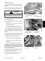
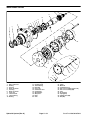
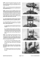
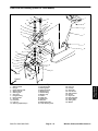
Engine (SP 2020/3020)
23
35
24
9
19
25
22
24
23
34
17
33
36
20
37
32
38
12 14
18 4
1
31
5
30
21
7
40
29
3
8
39 12
16
44
5
2
2
3
6
26
10
41
28
45
3
15
5
5
43
3
27
13
42
2
11
Figure 37
1.
2.
3.
4.
5.
6.
7.
8.
9.
10.
11.
12.
13.
14.
15.
Muffler
Cap screw
Flat washer
Muffler clamp
Hex nut
Screen
Muffler bracket
Fuel hose
Pop rivet
Flat washer
Lock washer
Fuel hose
Cap screw
R–clamp
Engine base
Engine
16.
17.
18.
19.
20.
21.
22.
23.
24.
25.
26.
27.
28.
29.
30.
Engine
Exhaust tube
Exhaust manifold
Air cleaner cover
Ring gasket
Air cleaner base
Muffler shield
Cap screw
Lock washer
Hot surface plate
Battery cable (Ground)
Red cable (Starter solenoid)
Hose clamp
Carburetor inlet shield
Screw
Page 3 – 22
31.
32.
33.
34.
35.
36.
37.
38.
39.
40.
41.
42.
43.
44.
45.
Air cleaner element
Cover plate
Air hose
Hose clamp
Air cleaner knob
Air cleaner knob
Washer face screw
Screw
Carburetor gasket
Manifold gasket
Screw
Boot
Wire harness (Ground wire)
Cable tie
Bumper
Sand Pro 2020/3020/5020
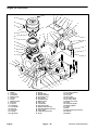
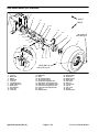
Engine Removal (Fig. 37)
6
3
8
1. Park machine on a level surface, lower attachment,
stop engine, engage parking brake, and remove key
from the ignition switch.
7
2. Pivot seat up. Remove engine cover. Remove move
litter box from fuel tank base.
3. Disconnect and remove battery from the machine to
prevent the possibility of the engine dropping on it (see
Battery Service in Chapter 5 – Electrical Systems).
NOTE: Do not disconnect brake linkages or remove
traverse rod when disconnecting the exhaust tube (17)
and muffler (1) from the engine (16).
4. Separate exhaust tube (17) and muffler (1) from the
exhaust manifold (see Muffler Removal).
1
2
5
4
Figure 38
1.
2.
3.
4.
5. Close fuel shutoff located below the fuel tank.
Clamp fuel hose (12) near engine (16) to prevent fuel
spillage. Loosen hose clamp (28) and remove fuel hose
(12) from the engine.
Cable on starter
Blue wire
Magneto terminal
Blue wire
5.
6.
7.
8.
Fusible link
Voltage regulator
Red/white wire
Red (+) battery cable
3
Engine
1
6. Remove cable tie from the starter and wire harness.
Disconnect harness as follows (Fig. 38):
A. Disconnect blue wire from magneto terminal.
2
B. Disconnect blue wire with fusible link from voltage regulator.
C. Disconnect red/white wire from fuel solenoid.
Figure 39
1. Cotter pin
2. Pump control rod
D. Disconnect red (+) cable from starter.
3. Pump lever
7. Remove air hose (33) from air cleaner cover (19).
8. Disconnect throttle control cable from the swivel
and choke control cable from the choke lever (see
Throttle and Choke Control Removal).
1
9. Remove cotter pin from the pump control rod. Separate rod from the pump lever (Fig. 39).
2
10. Loosen both set screws on the engine hub to remove hub from the pump shaft (Fig. 40).
11. Remove four cap screws and lock washers securing
the pump mount to the engine block. Pull pump and
mount from the engine and secure to frame. Remove
square key from engine shaft (Fig. 41).
Figure 40
1. Engine hub
12. Remove hex nut (5), lock washer (11), and cap
screw (13) securing the black (–) battery cable (26) and
wire harness (43) ground wire to the engine block. Pull
cable and harness clear of the engine (16).
13. Remove three hex nuts (5), flat washers (3), and
cap screws (13) securing the engine (16) to its base
(15).
Sand Pro 2020/3020/5020
2. Set screw (pump hub)
IMPORTANT: Make sure not to damage wires, wire
harness, hoses, and cables are while lifting the engine from the machine.
14. Connect hoist or chain fall to the engine. Slowly remove engine from the machine.
Page 3 – 23
Engine
Engine Installation (Fig. 37)
2
1
CAUTION
3
One person should operate the chain fall or hoist
while the other person guides the engine into the
frame.
1. Install engine (16) to the engine base (15).
A. Attach a hoist or chain fall to the engine.
Figure 41
IMPORTANT: Make sure not to damage the engine,
fuel and hydraulic lines, electrical harness, or other
parts while installing the engine.
1. Cap screw & lock washer
2. Pump mount
3. Engine block
10. Connect harness as follows (Fig. 38):
B. Lower engine slowly onto the engine base.
A. Connect blue wire to magneto terminal.
C. Insert cap screw (13) through engine base and
engine block. Install lock washer (11) onto cap
screw with battery cable (26) and wire harness (43).
Screw hex nut (5) onto the cap screw.
B. Connect blue wire with fusible link to voltage regulator.
C. Connect red/white wire to fuel solenoid.
D. Insert cap screws (13) through engine base and
engine block. Install flat washers (3) and screw hex
nuts (5) onto the cap screws. Do not tighten fasteners at this time.
E. Tighten all four fasteners securing the engine to
its base.
D. Connect red (+) cable to starter.
E. Secure wire harness with cable tie to the starter.
11. Install and connect battery to the machine (see Battery Service in Chapter 5 – Electrical Systems).
2. Place square key on the engine shaft.
12. Install litter box to the fuel tank base.
3. Position pump and pump mount to the engine. Make
sure engine hub slides onto the engine shaft and square
key (Fig. 40). Secure pump mount to the engine block
with four cap screws and lock washers (Fig. 41).
13. Install engine cover. Pivot seat down.
4. Tighten both set screws securing the engine hub to
the engine shaft (Fig. 40).
5. Insert end of pump control rod into the pump lever.
Secure rod with cotter pin (Fig. 39).
6. Connect throttle control cable to the swivel and
choke control cable to the choke lever (see Throttle and
Choke Control Installation).
7. Install air hose (33) to air cleaner cover (19). Secure
hose with hose clamp (34).
8. Secure fuel hose (12) to the engine (16) with hose
clamp (28). Remove clamp used to prevent drainage
from fuel hose (12). Open fuel shutoff located below the
fuel tank.
9. Connect exhaust tube and muffler to the exhaust
manifold (see Muffler Installation).
Engine
Page 3 – 24
Sand Pro 2020/3020/5020
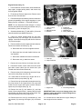
Replace Spark Plugs
Replace spark plugs after every 800 operating hours or
yearly, which ever occurs first. Recommended air gap is
0.030 inch (0.762 mm). Use a Champion RC 12YC
spark plug or equivalent.
0.030 inch
0.762 mm
NOTE: A spark plug usually lasts a long time. However,
remove. Check spark plugs whenever the engine malfunctions.
IMPORTANT: A cracked, fouled, dirty, or otherwise
malfunctioning spark plug must be replaced. Do not
sand blast, scrape, or clean electrodes by using a
wire brush because grit may be released from the
plug and fall into the cylinder. The result is usually
a damaged engine.
1. Clean area around spark plugs so foreign matter
cannot fall into cylinder when spark plug is removed.
3. Check condition of side electrode, center electrode,
and center electrode insulator. Make sure there is no
damage.
Sand Pro 2020/3020/5020
4. Set air gap between the center and side of the electrodes at 0.030 inch (0.762 mm). Install correctly
gapped spark plug with gasket seal. Tighten spark plug
to 200 in–lb (230 kg–cm). If torque wrench is not used,
tighten plug firmly.
Page 3 – 25
Engine
Engine
2. Pull spark plug wires off spark plugs. Remove plugs
from cylinder head.
Figure 42
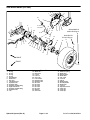
Engine (SP 5020)
1
2
3
52
7
4
8
9
10
11
51
6
49
12
48
13
6
47
40 17
46
15
18
14
16
54
19
43
20
45
26
21
44
22
53
28
20
30
24
27
29
25
23
31
32
38
33
55
36
35
37
30
34
Figure 43
1.
2.
3.
4.
5.
6.
7.
8.
9.
10.
11.
12.
13.
14.
15.
16.
17.
18.
19.
Air cleaner knob
Air cleaner cover
Cover seal
Air cleaner knob
Not used
Hex flange head screw
Cap screw
Lock washer
Pop rivet
Hot surface plate
Muffler shield
Screw
Exhaust deflector
Muffler
Screw
Exhaust gasket
Hose clamp
Rubber guard
Fuel hose
Engine
20.
21.
22.
23.
24.
25.
26.
27.
28.
29.
30.
31.
32.
33.
34.
35.
36.
37.
Lock nut
Battery cable (negative)
Cable cover
Cable tie
Lock washer
Positive cable (from starter solenoid))
Ground wire (to frame)
Stub shaft
Lock nut
Cap screw
Flat washer
Engine mount
Lock nut
Engine support
Cap screw
Cap screw
Cap screw
Cap screw
Page 3 – 26
38.
39.
40.
41.
42.
43.
44.
45.
46.
47.
48.
49.
50.
51.
52.
53.
54.
55.
Engine base
Not used
Carburetor gasket
Not used
Not used
Cap screw
Cap screw
Screen/spacer
Engine
Fuel hose
Air cleaner base
Carburetor inlet shield
Not used
Filter element
Cover plate
Cover
Cap screw
Cap screw
Sand Pro 2020/3020/5020
Engine Removal (Fig. 43)
1
1. Park machine on a level surface, lower attachment,
stop engine, engage, and remove key from the ignition
switch.
3
2. Chock wheels to prevent the machine from moving.
The brake assembly will be partially disassembled.
4
CAUTION
2
The muffler and exhaust pipe may be hot. To
avoid possible burns, allow engine and exhaust
system to cool before working near muffler.
Figure 44
1. Cotter pin & flat washer
2. Seat rod
3. Lock nut
4. Cap screw & flat washer
3. Remove attachment from the rear of the machine to
gain access to the engine.
1
3
A. Separate seat rod from the base by removing
cotter pin and flat washer.
4
B. Separate base from frame by removing both lock
nuts, cap screws, flat washers, and spacers.
5. Disconnect and remove battery from the machine to
prevent the possibility of the engine damaging it during
removal (see Battery Service in Chapter 5 – Electrical
Systems).
2
Figure 45
1. Blue wire (magneto)
2. Blue wire (voltage reg.)
3. Voltage regulator
4. Red/white wire
6. Close fuel shutoff valve. Clamp fuel hose near engine to prevent fuel spillage. Loosen hose clamp at fuel
pump and remove fuel hose from the pump.
7. Disconnect wire harness as follows (Fig. 45):
2
A. Disconnect blue wire from magneto terminal.
B. Disconnect blue wire with fusible link from voltage regulator.
C. Disconnect red/white wire from fuel solenoid.
IMPORTANT: Keep air cleaner base removed from
the carburetor after disconnecting the choke cable
from the choke lever. This is necessary to remove
the engine from the machine.
1
Figure 46
1. Set screw
2. Engine hub
8. Disconnect throttle control cable from the swivel
and choke control cable from the choke lever (see
Throttle and Choke Control Removal).
9. Loosen both set screws on the engine hub to remove hub from the engine shaft (Fig. 46).
Sand Pro 2020/3020/5020
Page 3 – 27
Engine
Engine
4. Pivot seat up. Remove seat base with seat attached
as follows (Fig. 44):
10. Disconnect red positive cable cable (solenoid) from
the starter (Fig. 47).
11. Remove lock nut and cap screw securing black
ground wire and black battery cable (negative) to the engine block. Pull cable and harness clear of the engine
(Fig. 47).
1
2
12. Remove remaining three lock nuts and cap screws
securing the engine to its base.
5
4
CAUTION
3
Figure 47
Before jacking up the machine, review and follow
Jacking Instructions in Chapter 1 – Safety.
1. Positive cable (solenoid)
2. Starter
3. Lock nut and cap screw
4. Battery cable (negative)
5. Ground wire (frame)
One person should operate the jack while the
other person guides the engine from the frame
and engine base.
3
IMPORTANT: Make sure not to damage wires, wire
harness, hoses, and cables while removing the engine from the machine.
2
13. Remove engine as follows (Fig. 43 and 48):
A. Position a jack under the rear of the engine base.
B. Support engine with a jack, then remove cap
screws and flat washers securing the engine support to the frame.
IMPORTANT: When the rear of the engine base is
lowered, the base will pivot at the front engine
mounts. Lower base about 1 inch (2.5 cm), which is
enough to allow the top of the engine to clear the traverse rod. Avoid damaging the cooling fan and oil
cooler as the hydrostat pivots up. The engine
should then slide off the base. Do not allow engine
to drop.
4
1
1
Figure 48
1.
2.
Cap screw & flat washer
Engine support
3. Traverse rod
4. Engine base
1. Install engine to its base as follows (Fig. 43 and 48):
A. Attach a jack to the rear of the engine base.
B. Make sure square key is placed on the shaft.
Position engine onto the engine base. Slide engine
shaft into the engine hub
C. Lower rear of the engine base. Remove engine
from the engine hub and base. Remove square key
from the engine shaft.
C. Insert three cap screws through engine base
and engine block. Install lock nuts to the cap screws.
Do not tighten fasteners at this time.
14. Secure engine base and hydrostat to prevent the
cooling fan from damaging the oil cooler.
D. Insert cap screw through engine base and engine block. Connect black ground wire and black
battery cable (negative) to the cap screw. Screw
lock nut onto the cap screw (Fig. 47).
Engine Installation (Fig. 43)
E. Tighten all four fasteners securing the engine to
its base.
CAUTION
F. Jack up engine base enough to secure the engine support to the frame. Secure engine support to
the frame cap screws and flat washer.
One person should operate the jack while the
other person guides the engine into the frame.
IMPORTANT: Make sure not to damage the engine,
fuel and hydraulic lines, electrical harness, or other
parts while installing the engine.
Engine
2. Connect red positive cable cable (solenoid) to the
starter (Fig. 47).
Page 3 – 28
Sand Pro 2020/3020/5020
3. Tighten both set screws on the engine hub to secure
hub to the engine shaft (Fig. 46).
6. Install seat base with seat attached to the frame as
follows (Fig. 44):
4. Connect throttle control cable to the swivel and
choke control cable to the choke lever (see Throttle and
Choke Control Installation).
A. Position base on machine. Secure base to frame
with both spacers, cap screws, flat washers, and
lock nuts.
5. Connect wire harness as follows (Fig. 45):
B. Secure seat rod to the base with flat washer and
cotter pin.
A. Connect blue wire to the magneto terminal.
B. Connect blue wire with fusible link to voltage regulator.
8. Secure fuel hose to the fuel pump with hose clamp.
Remove clamp from fuel hose that was used to prevent
fuel spillage. Open fuel shutoff valve.
Engine
C. Connect red/white wire to fuel solenoid.
7. Install and connect battery to the machine (see Battery Service in Chapter 5 – Electrical Systems).
Sand Pro 2020/3020/5020
Page 3 – 29
Engine
Clean Cylinder Head Fins
Avoid overheating and possible damage to the engine.
Keep cooling fins on cylinder heads clean.
1
1. Park machine on a level surface, lower attachment,
stop engine, engage parking brake, and remove key
from the ignition switch.
3
2. Gain access to the engine.
NOTE: The engines on the SP 2020/3020 and SP 5020
are constructed the same. The SP 2020/3020 engine is
shown.
2
Figure 49
3. Remove muffler shield and both air guide covers to
gain access to both cylinder heads.
1. Muffler shield
2. Air guide cover (LH)
3. Cylinder head (LH)
1
CAUTION
2
Use eye protection such as goggles when using
compressed air.
3
4. Blow dirt and debris from between the cooling fins
and away from the engine.
5. Use nylon bristle brush and hot soapy water to remove any encrusted mud or other debris on and between the cooling fins. Rinse fins with clear water after
cleaning.
Figure 50
1. Muffler shield
2. Air guide cover (RH)
3. Cylinder head (RH)
6. Secure both air guide covers and muffler shield to
the engine.
7. Install engine cover to the machine.
Engine
Page 3 – 30
Sand Pro 2020/3020/5020
Chapter 4
Hydraulic Systems
Table of Contents
Sand Pro 2020/3020/5020
Hydrostat (SP 5020) . . . . . . . . . . . . . . . . . . . . . . . .
Removal . . . . . . . . . . . . . . . . . . . . . . . . . . . . . . . . . .
Installation . . . . . . . . . . . . . . . . . . . . . . . . . . . . . . . .
Flush Hydraulic System . . . . . . . . . . . . . . . . . . . . . .
Hydrostat Service . . . . . . . . . . . . . . . . . . . . . . . . . . .
Charge Pump Disassembly, Inspection,
and Assembly . . . . . . . . . . . . . . . . . . . . . . . . . . . .
Shaft Seal Removal and Installation . . . . . . . . . .
Acceleration Valve Disassembly, Inspection,
and Assembly . . . . . . . . . . . . . . . . . . . . . . . . . . . .
Charge and Implement Relief Valve
Disassembly, Inspection, and Assembly . . . . .
Charge Check Valve Disassembly,
Inspection, and Assembly . . . . . . . . . . . . . . . . .
Traction Pump Disassembly . . . . . . . . . . . . . . . . .
Traction Pump Inspection . . . . . . . . . . . . . . . . . . .
Traction Pump Assembly . . . . . . . . . . . . . . . . . . . .
Front Wheel Motor . . . . . . . . . . . . . . . . . . . . . . . . . .
Removal . . . . . . . . . . . . . . . . . . . . . . . . . . . . . . . . . .
Installation . . . . . . . . . . . . . . . . . . . . . . . . . . . . . . . .
Rear Wheel Motors (SP 2020/3020) . . . . . . . . . . .
Removal and Installation . . . . . . . . . . . . . . . . . . . .
Rear Wheel Motors (SP 5020) . . . . . . . . . . . . . . . .
Removal and Installation . . . . . . . . . . . . . . . . . . . .
Wheel Motor Service . . . . . . . . . . . . . . . . . . . . . . . .
Disassembly . . . . . . . . . . . . . . . . . . . . . . . . . . . . . .
Inspection . . . . . . . . . . . . . . . . . . . . . . . . . . . . . . . . .
Assembly . . . . . . . . . . . . . . . . . . . . . . . . . . . . . . . . .
Hydraulic Tank (SP 2020/3020) . . . . . . . . . . . . . . .
Removal, Inspection, and Installation . . . . . . . . .
Hydraulic Oil Cooler (SP 2020/3020) . . . . . . . . . .
Removal, Inspection, and Installation . . . . . . . . .
Hydraulic Tank and Oil Cooler (SP 5020) . . . . . .
Oil Cooler Removal . . . . . . . . . . . . . . . . . . . . . . . .
Oil Cooler Inspection . . . . . . . . . . . . . . . . . . . . . . .
Oil Cooler Installation . . . . . . . . . . . . . . . . . . . . . . .
Hydraulic Tank Removal,
Inspection, and Installation . . . . . . . . . . . . . . . .
Page 4 – 1
44
44
45
47
48
49
50
51
51
51
52
53
54
56
56
57
58
59
60
61
62
63
64
66
70
71
72
73
74
74
75
76
76
Hydraulic System (Rev. A)
Hydraulic
Systems
SPECIFICATIONS . . . . . . . . . . . . . . . . . . . . . . . . . . . . 2
GENERAL INFORMATION . . . . . . . . . . . . . . . . . . . . . 3
Hydraulic Hoses . . . . . . . . . . . . . . . . . . . . . . . . . . . . . 3
Hydraulic Fitting Installation . . . . . . . . . . . . . . . . . . . 3
Towing Traction Unit . . . . . . . . . . . . . . . . . . . . . . . . . 5
Check Hydraulic System Fluid . . . . . . . . . . . . . . . . . 5
HYDRAULIC SCHEMATICS . . . . . . . . . . . . . . . . . . . . 6
Sand Pro 2020/3020 . . . . . . . . . . . . . . . . . . . . . . . . . 6
Sand Pro 5020 . . . . . . . . . . . . . . . . . . . . . . . . . . . . . . 7
HYDRAULIC FLOW DIAGRAMS . . . . . . . . . . . . . . . . 8
Traction Forward . . . . . . . . . . . . . . . . . . . . . . . . . . . . 8
Traction Reverse . . . . . . . . . . . . . . . . . . . . . . . . . . . 10
Retract and Extend Lift Cylinder . . . . . . . . . . . . . . 12
SPECIAL TOOLS . . . . . . . . . . . . . . . . . . . . . . . . . . . . 14
Hydraulic Pressure Test Kit . . . . . . . . . . . . . . . . . . . 14
Hydraulic Tester – Pressure and Flow . . . . . . . . . 14
Hydraulic Test Fittings . . . . . . . . . . . . . . . . . . . . . . . 15
TROUBLESHOOTING . . . . . . . . . . . . . . . . . . . . . . . . 16
TESTING . . . . . . . . . . . . . . . . . . . . . . . . . . . . . . . . . . . 19
Precautions for Hydrostatic Testing . . . . . . . . . . . . 19
TEST NO. 1: Traction Pump Flow (P1) . . . . . . . . 20
TEST NO. 2: Charge Relief Valve (R2)
and Implement Relief Valve (R1) . . . . . . . . . . . . 22
TEST NO. 3: Charge Pump (P2) Flow . . . . . . . . . 24
TEST NO. 4: Wheel Motor Efficiency . . . . . . . . . . 26
ADJUSTMENTS . . . . . . . . . . . . . . . . . . . . . . . . . . . . . 28
Adjust Traction Pedal for Neutral . . . . . . . . . . . . . . 28
Adjust Traction Pedal for Forward
(SP 2020/3020) . . . . . . . . . . . . . . . . . . . . . . . . . . . 28
Adjust Traction Pedal for Forward (SP 5020) . . . 29
Adjust LIft Lever (SP 2020/3020) . . . . . . . . . . . . . 30
Adjust LIft Lever (SP 5020) . . . . . . . . . . . . . . . . . . . 30
SERVICE AND REPAIRS . . . . . . . . . . . . . . . . . . . . . 31
Check Hydraulic Lines and Hoses . . . . . . . . . . . . . 31
Charge Hydraulic System . . . . . . . . . . . . . . . . . . . . 31
Change Hydraulic System Fluid and Filter . . . . . . 32
Lift Valve (SP 2020/3020) . . . . . . . . . . . . . . . . . . . . 34
Removal and Installation . . . . . . . . . . . . . . . . . . . . 35
Lift Valve (SP 5020) . . . . . . . . . . . . . . . . . . . . . . . . . 36
Removal and Installation . . . . . . . . . . . . . . . . . . . . 37
Lift Valve Service . . . . . . . . . . . . . . . . . . . . . . . . . . . 38
Lift Cylinder (SP 2020/3020) . . . . . . . . . . . . . . . . . 39
Lift Cylinder (SP 5020) . . . . . . . . . . . . . . . . . . . . . . 40
Lift Cylinder Service . . . . . . . . . . . . . . . . . . . . . . . . . 41
Hydrostat (SP 2020/3020) . . . . . . . . . . . . . . . . . . . 42
Removal . . . . . . . . . . . . . . . . . . . . . . . . . . . . . . . . . . 42
Installation . . . . . . . . . . . . . . . . . . . . . . . . . . . . . . . . 43
Specifications
Item
Description
Hydrostatic Transmission
Pump Displacement
Pump Flow Rate (@ 3150 RPM)
Maximum Continuous Rated Speed
Maximum Intermittent Rated Speed
Maximum Operating Pressure
Maximum Intermittent Pressure
Charge Pump Displacement
Charge Pump Flow Rate (@ 3150 RPM)
Charge Relief Setting
Maximum Inlet Vacuum
Maximum Continuous Case Pressure
Maximum (Cold Start) Case Pressure
Implement Relief Setting
Variable displacement piston pump
0.913 in3/rev (15.0 cm3/rev)
12.5 GPM (47.2 LPM)
4000 RPM
4200 RPM
2500 PSI (175 bar)
4500 PSI (310 bar)
0.33 in3/rev (5.4 cm3/rev)
4.5 GPM (17.0 LPM)
90 to 180 PSI (4.8 to 10.4 bar)
5 inch Hg
10 PSI (0.7 bar)
25 PSI (1.7 bar)
700 to 800 PSI (48.3 to 55.2 bar)
Right Wheel Motors (SP 2020/SP 3020)
Motor Displacement
Maximum Operating Pressure
Maximum Intermittent Pressure
Maximum Flow
Rated Speed @ Maximum Flow
Orbital rotor vane with shuttle valve
7.8 in3/rev (127.8 cm3/rev)
2000 PSI (138 bar)
3000 PSI (207 bar)
20 GPM (76 LPM)
583 RPM
Right Wheel Motors (SP 5020)
Motor Displacement
Maximum Operating Pressure
Maximum Intermittent Pressure
Maximum Flow
Rated Speed @ Maximum Flow
Orbital rotor vane with reverse timed manifold and shuttle valve
8.6 in3/rev (140.1 cm3/rev)
2000 PSI (138 bar)
3000 PSI (207 bar)
20 GPM (76 LPM)
530 RPM
Left Wheel Motors (SP 2020/SP 3020)
Motor Displacement
Maximum Operating Pressure
Maximum Intermittent Pressure
Maximum Flow
Rated Speed @ Maximum Operating Pressure and Rated Flow
Orbital rotor vane
7.8 in3/rev (127.8 cm3/rev)
2000 PSI (138 bar)
3000 PSI (207 bar)
20 GPM (76 LPM)
583 RPM
Left Wheel Motors (SP 5020)
Motor Displacement
Maximum Operating Pressure
Maximum Intermittent Pressure
Maximum Flow
Rated Speed @ Maximum Flow
Orbital rotor vane
8.6 in3/rev (140.9 cm3/rev)
2000 PSI (138 bar)
3000 PSI (207 bar)
20 GPM (76 LPM)
530 RPM
Front Wheel Motor (SP 3020)
Motor Displacement
Maximum Operating Pressure
Maximum Intermittent Pressure
Maximum Flow
Rated Speed @ Maximum Flow
Orbital rotor motor
5.0 in3/rev (81.9 cm3/rev)
3000 PSI (207 bar)
4000 PSI (276 bar)
12 GPM (45 LPM)
693 RPM
Front Wheel Motor (SP 5020)
Motor Displacement
Maximum Operating Pressure
Maximum Intermittent Pressure
Maximum Flow
Rated Speed @ Maximum Flow
Orbital rotor vane with reverse timed manifold
17.1 in3/rev (280.3 cm3/rev)
2000 PSI (138 bar)
3000 PSI (207 bar)
25 GPM (95 LPM)
334 RPM
Hydraulic Filter
Hydraulic Oil
25 Micron spin on cartridge type
See Check Hydraulic System Fluid in General section
Hydraulic Tank
Hydraulic System
Tank capacity 3.0 gal. U.S. (20.8 L)
Page 4 – 2 Rev. B
Sand Pro 2020/3020/5020
General Information
Hydraulic Hoses
When replacing a hydraulic hose, be sure that the hose
is straight (not twisted) before tightening the fittings.
This can be done by observing the imprint on the hose.
Use two wrenches; hold the hose straight with one and
tighten the hose swivel nut onto the fitting with the other.
WARNING
Before disconnecting or performing any work
on hydraulic system, relieve all pressure in
system. Stop engine; lower or support box
and/or other attachment(s).
Keep body and hands away from pin hole leaks
or nozzles that eject hydraulic fluid under high
pressure. Use paper or cardboard, not hands,
to search for leaks. Hydraulic fluid escaping
under pressure can have sufficient force to
penetrate the skin and cause serious injury. If
fluid is injected into the skin, it must be surgically removed within a few hours by a doctor
familiar with this type of injury. Gangrene may
result from such an injury.
Hydraulic Fitting Installation
O–Ring Face Seal
Nut
1. Make sure both threads and sealing surfaces are
free of burrs, nicks, scratches, or any foreign material.
Body
Sleeve
2. Make sure the O–ring is installed and properly
seated in the groove. It is recommended that the O–ring
be replaced any time the connection is opened.
Seal
3. Lubricate the O–ring with a light coating of oil.
4. Put the tube and nut squarely into position on the
face seal end of the fitting and tighten the nut until finger
tight.
Figure 1
5. Mark the nut and fitting body. Hold the body with a
wrench. Use another wrench to tighten the nut to the correct flats from finger tight (F.F.F.T.). The markings on the
nut and fitting body will verify that the connection has
been tightened.
Size
4 (1/4 in. nominal hose or tubing)
6 (3/8 in.)
8 (1/2 in.)
10 (5/8 in.)
12 (3/4 in.)
16 (1 in.)
Sand Pro 2020/3020/5020
Final
Position
Mark Nut
and Body
F.F.F.T.
0.75 + 0.25
0.75 + 0.25
0.75 + 0.25
1.00 + 0.25
0.75 + 0.25
0.75 + 0.25
Page 4 – 3
Extend Line
Finger Tight
Initial
Position
After Proper Tightening
Figure 2
Hydraulic System (Rev. A)
Hydraulic
Systems
Hydraulic hoses are subject to extreme conditions such
as pressure differentials during operation and exposure
to weather, sun, chemicals, very warm storage conditions, or mishandling during operation or maintenance.
These conditions can cause damage or premature deterioration. Some hoses are more susceptible to these
conditions than others. Inspect the hoses frequently for
signs of deterioration or damage.
SAE Straight Thread O–Ring Port – Non–adjustable
1. Make sure both threads and sealing surfaces are
free of burrs, nicks, scratches, or any foreign material.
2. Always replace the O–ring seal when this type of fitting shows signs of leakage.
O–Ring
3. Lubricate the O–ring with a light coating of oil.
4. Install the fitting into the port and tighten it down full
length until finger tight.
Figure 3
5. Tighten the fitting to the correct flats from finger tight
(F.F.F.T.).
Size
4 (1/4 in. nominal hose or tubing)
6 (3/8 in.)
8 (1/2 in.)
10 (5/8 in.)
12 (3/4 in.)
16 (1 in.)
F.F.F.T.
1.00 + 0.25
1.50 + 0.25
1.50 + 0.25
1.50 + 0.25
1.50 + 0.25
1.50 + 0.25
SAE Straight Thread O–Ring Port – Adjustable
1. Make sure both threads and sealing surfaces are
free of burrs, nicks, scratches, or any foreign material.
2. Always replace the O–ring seal when this type of fitting shows signs of leakage.
Lock Nut
3. Lubricate the O–ring with a light coating of oil.
4. Turn back the jam nut as far as possible. Make sure
the back up washer is not loose and is pushed up as far
as possible (Step 1).
Back–up Washer
O–Ring
5. Install the fitting into the port and tighten finger tight
until the washer contacts the face of the port (Step 2).
6. To put the fitting in the desired position, unscrew it
by the required amount, but no more than one full turn
(Step 3).
Figure 4
Step 1
Step 3
Step 2
Step 4
7. Hold the fitting in the desired position with a wrench
and turn the jam nut with another wrench to the correct
flats from finger tight (F.F.F.T.) (Step 4).
Size
4 (1/4 in. nominal hose or tubing)
6 (3/8 in.)
8 (1/2 in.)
10 (5/8 in.)
12 (3/4 in.)
16 (1 in.)
Hydraulic System (Rev. A)
F.F.F.T.
1.00 + 0.25
1.50 + 0.25
1.50 + 0.25
1.50 + 0.25
1.50 + 0.25
1.50 + 0.25
Page 4 – 4
Figure 5
Sand Pro 2020/3020/5020
Towing Traction Unit
In case of emergency, the Sand Pro can be towed for a
short distance. However, Toro does not recommend this
as a standard procedure.
IMPORTANT: Do not tow the machine faster than 2
to 3 mph because drive system may be damaged. If
machine must be moved a considerable distance,
transport it on a truck or trailer. Tires may lock up if
machine is towed too fast. If lock up occurs, stop
towing the machine. Wait for the traction circuit
pressure to stabilize before resuming towing at a
slower speed.
Check Hydraulic System Fluid
The hydraulic system is designed to operate on Mobil
424 hydraulic oil. The machine’s 3 gallon tank is filled at
the factory with oil. However, check oil level before the
engine is first started and daily thereafter.
1
2
1. Remove cap from the hydraulic oil tank.
2. Check oil level in the tank. Oil level should be up to
the top of the cone point on tank screen.
IMPORTANT: To prevent system contamination,
clean top of hydraulic oil containers before puncturing. Assure pour spout and funnel are clean.
1.
Cap
2.
Tank (SP 2020/3020)
1
NOTE: The fluids within this group are interchangeable.
Group 1 Hydraulic Fluid (Recommended for ambient
temperatures consistently below 100o F.):
ISO type 46/68 anti–wear hydraulic fluid
Mobil
Amoc
International Harvester
Texaco
Shell
Union OIl
Chevron
BP Oil
Boron OIl
Exxon
Conoco
Kendall
Phillips
Mobil Fluid 424
Amoco 1000
Hy–Tran
TDH
Donax TD
Hydraulic/Tractor Fluid
Tractor Hydraulic Fluid
BP HYD TF
Eldoran UTH
Torque Fluid
Power–Tran 3
Hyken 052
HG Fluid
2
Figure 7
1.
Cap
2.
Tank (SP 5020)
4. Install tank cap.
Sand Pro 2020/3020/5020
Page 4 – 5
Hydraulic System (Rev. A)
Hydraulic
Systems
Figure 6
3. If fluid level is low, slowly fill tank with appropriate hydraulic fluid until level reaches bottom of screen. DO
NOT OVERFILL.
Hydraulic System
OIL COOLER
P1
TRACTION
PUMP
HYDROSTAT
TANK
P2
CHARGE
PUMP
FILTER
CHARGE
CHECK
VALVE
CHARGE
CHECK
VALVE
CHARGE
RELIEF
LIFT VALVE
ACCELERATION
VALVES
B
*
Page 4 – 6 Rev. B
LIFT CYLINDER
OPTIONAL
ORIFICE
R2
R1
IMPLEMENT
RELIEF
A
M2
SP 3020 ONLY
M3
FRONT
RIGHT
M1
RH WHEEL MOTOR
WITH BLEED OFF
FOR OIL COOLING
IN FORWARD
B
0.915
0.33
7.8
7.8
5.0
–
–
15
5.41
127.84
127.84
81.97
–
–
12.48
4.5
–
–
–
–
–
–
–
–
–
–
48.3
6.2
–
–
–
–
–
700
90
Sand Pro 2020/3020
Hydraulic Schematic
FLOW RATE CALCULATED AT 3150 RPM
R1
R2
P1
P2
M1
M2
M3
–
–
47.2
17
–
–
–
DISPLACEMENT, FLOW RATE, AND PRESSURE CHART
*FLOW RATE
DISPLACEMENT
PRESSURE
COMPONENT in 3 /rev
cm 3 /rev lbs/in 2 BARS GPM LPM
FORWARD
LEFT
A
HOT OIL
SHUTTLE
VALVE
Hydraulic Schematics
*
*
Sand Pro 2020/3020/5020
Sand Pro 2020/3020/5020
Page 4 – 7
OIL COOLER
P1
TRACTION
PUMP
HYDROSTAT
TANK
P2
CHARGE
PUMP
FILTER
CHARGE
CHECK
VALVE
CHARGE
CHECK
VALVE
R2
R1
M3
FRONT AND RH WHEEL
MOTORS HAVE REVERSE
TIMED MANIFOLDS
RIGHT
M1
RH WHEEL MOTOR
WITH BLEED OFF
FOR OIL COOLING
IN FORWARD
A
B
HOT OIL
SHUTTLE
VALVE
FLOW RATE CALCULATED AT 3150 RPM
–
–
–
–
–
17
–
47.2
Sand Pro 5020
Hydraulic Schematic
6.2
–
90
700
–
–
R2
R1
–
48.3
17.1
–
M3
–
280.22
–
8.6
M2
–
4.5
–
–
–
–
–
140.93
8.6
M1
12.48
–
–
–
–
5.41
0.33
140.93
–
15
0.915
P1
DISPLACEMENT, FLOW RATE, AND PRESSURE CHART
*FLOW RATE
DISPLACEMENT
PRESSURE
cm 3 /rev
COMPONENT in 3 /rev
lbs/in 2 BARS GPM LPM
FORWARD
FRONT
M2
P2
B
LEFT
*
Hydraulic System (Rev. A)
Hydraulic
Systems
LIFT VALVE
ACCELERATION
VALVES
LIFT CYLINDER
CHARGE
RELIEF
IMPLEMENT
RELIEF
A
*
*
Hydraulic Flow Diagrams
Traction Forward
The traction circuit of the hydraulic system consists of a
hydrostat connected in a closed loop circuit to three orbital vane wheel motors. Hydraulic fluid losses are designed to occur from case drain leakage of the traction
pump (P1) and bleed off from the right wheel motor (M1).
These losses are replenished by the charge pump (P2),
which is integral to the hydrostat.
The engine drives traction pump (P1) directly through a
coupling. The traction pump is a variable displacement
piston pump. The traction pedal connects through a linkage to the trunnion shaft and swash plate of the pump.
With the engine running and the traction pedal in the
neutral position, P2 supplies no flow to the wheel motors. When the traction pedal is pressed to the forward
position, the linkage from the pedal positions the swash
plate in the traction pump so oil flows out port B. Oil flow
out of port B goes to the wheel motors and turns them
in the forward direction. On the SP 5020, the oil flow
goes through the front motor first and then through the
left and right rear wheel motors. Oil flowing out of the
wheel motors returns to port A of the hydrostat and is
continuously pumped out of port B.
The hydrostat uses a small amount of hydraulic fluid for
internal lubrication. Fluid is designed to leak across
pump parts into the case drain. This leakage results in
the loss of hydraulic fluid from the closed loop circuit that
must be replenished.
Hydraulic System (Rev. A)
The charge pump (P2) is a fixed displacement gerotor
pump. It is driven directly off the traction pump. The
pump replenishes the closed loop circuit with fluid from
the tank. The charge relief valve (R2) supplies sufficient
head so that charge pump flow is guided to the low pressure side of the traction circuit through one of two check
valves. Pump flow in excess of replenishment requirements is relieved through the charge relief valve back to
the tank.
The right wheel motor bleeds off a small amount of hydraulic fluid for cooling of the closed loop circuit. This
bleed off happens in the forward direction only. The high
pressure side of the motor forces a shuttle spool to shift
against a spring. The pressure drop across the motor
causes a small amount of fluid to bleed off through a
fixed orifice on the low pressure side of the motor and
then through the shuttle spool. This bleed off returns to
the tank through the oil cooler.
The acceleration valves reduce the rate of change in acceleration (jerkiness) when hydrostat output is increased by the action of the operator. An increase of
pressure on the output side of the hydrostat will by–pass
some pump flow to the low pressure side of the pump.
The valve on the high pressure side closes at a predetermined rate as pressure increases. This gives the hydrostat a smooth acceleration rate when the swashplate
is stroked rapidly.
Page 4 – 8
Sand Pro 2020/3020/5020
Sand Pro 2020/3020/5020
Page 4 – 9
Hydraulic System (Rev. A)
TANK
P2
CHARGE
PUMP
High Pressure
Low Pressure (Charge)
Return or Suction
Flow
Sand Pro 2020/3020/5020
Traction Forward
OIL COOLER
P1
TRACTION
PUMP
HYDROSTAT
FILTER
CHARGE
CHECK
VALVE
CHARGE
CHECK
VALVE
R2
R1
LIFT VALVE
ACCELERATION
VALVES
Hydraulic
Systems
LIFT CYLINDER
CHARGE
RELIEF
IMPLEMENT
RELIEF
B
A
M3
FRONT
M3
FRONT
M2
FORWARD
RIGHT
RIGHT
FRONT AND RH WHEEL
MOTORS HAVE REVERSE
TIMED MANIFOLDS
LEFT
SP 3020 ONLY
TO LIFT VALVE
B
A
FORWARD
M2
LEFT
M1
SP 5020
RH WHEEL MOTOR
WITH BLEED OFF
FOR OIL COOLING
IN FORWARD
B
RH WHEEL MOTOR
WITH BLEED OFF
FOR OIL COOLING
IN FORWARD
A
B
M1
A
HOT OIL
SHUTTLE
VALVE
Traction Reverse
The traction circuit operates essentially the same in reverse as it does in forward. However, there are a few differences in operation.
When the traction pedal is pressed to the reverse position, the linkage from the pedal positions the swash plate
in the traction pump so oil flows out of port A. Oil flow out
of port A goes to the wheel motors and turns them in the
reverse direction. On the SP 5020, the oil flow goes
through the left and right rear wheel motors first and then
through the front wheel motor. Oil flowing out of the
wheel motors returns to port B of the hydrostat and is
continuously pumped out of port A.
The right wheel motor does not bleed off any hydraulic
fluid for cooling of the closed loop circuit in the reverse
direction.
Hydraulic System (Rev. A)
Page 4 – 10
Sand Pro 2020/3020/5020
Sand Pro 2020/3020/5020
Page 4 – 11
Hydraulic System (Rev. A)
TANK
P2
CHARGE
PUMP
High Pressure
Low Pressure (Charge)
Return or Suction
Flow
Sand Pro 2020/3020/5020
Traction Reverse
OIL COOLER
P1
TRACTION
PUMP
HYDROSTAT
FILTER
CHARGE
CHECK
VALVE
CHARGE
CHECK
VALVE
R2
R1
Hydraulic
Systems
LIFT VALVE
ACCELERATION
VALVES
LIFT CYLINDER
CHARGE
RELIEF
IMPLEMENT
RELIEF
B
A
M2
M3
FRONT
M3
FRONT
M2
FORWARD
RIGHT
RIGHT
FRONT AND RH WHEEL
MOTORS HAVE REVERSE
TIMED MANIFOLDS
LEFT
SP 3020 ONLY
TO LIFT VALVE
B
A
LEFT
REVERSE
M1
SP 5020
RH WHEEL MOTOR
WITH BLEED OFF
FOR OIL COOLING
IN FORWARD
B
RH WHEEL MOTOR
WITH BLEED OFF
FOR OIL COOLING
IN FORWARD
A
B
M1
A
HOT OIL
SHUTTLE
VALVE
Retract and Extend Lift Cylinder
The hydraulic lift circuits for the SP 2020/3020 and SP
5020 function identically. Each machine has identical
charge pumps, lift valves, and lift cylinders. These components are the heart of the lift circuit.
In addition to replenishing the closed loop circuit with
fluid from the tank, charge pump (P2) flow in excess of
replenishment requirements is relieved through the
charge relief valve (R2). Fluid returns through the lift
valve and back to the tank. This excess flow is used to
operate the lift cylinder.
The charge pump is a fixed displacement gerotor pump
that is driven directly off the traction pump (P1). It has
sufficient output to handle intermittent operation of the
lift cylinder under load. The implement relief valve (R1)
in the charge circuit allows high enough pressure to operate the lift cylinder with attachments, and protects the
charge pump.
When the lift lever to the lift valve is in the neutral position, fluid flow from the charge pump is bypassed around
the lift cylinder through the lift valve. Fluid returns to the
tank as a normal part of the charge and bleed off circuits.
Hydraulic System (Rev. A)
Moving the lift lever to the lift position allows the lift valve
to direct fluid flow from the charge pump into the rod side
of the piston. The piston moves into the cylinder pushing
fluid out the piston end of the cylinder and to the tank. As
the cylinder rod retracts, the attachment is raised. When
the lift lever is released, the lift valve returns to the neutral position. The attachment is held in its present position.
Moving the lift lever to the lower position allows the lift
valve to direct fluid flow from the charge pump into the
piston side of the cylinder. The piston moves out of the
cylinder pushing fluid out the rod end of the cylinder and
to the tank. As the cylinder rod extends, the attachment
is lowered. When the lift lever is released, the lift valve
returns to the neutral position. The attachment is held in
its present position.
Excessive load on the lift cylinder causes circuit pressure to increase and the implement relief valve (R1) to
dump directly to the tank. This condition happens in both
the lift and lower modes.
Page 4 – 12
Sand Pro 2020/3020/5020
Sand Pro 2020/3020/5020
Page 4 – 13
Hydraulic System (Rev. A)
P1
TANK
P2
CHARGE
PUMP
High Pressure
Low Pressure (Charge)
Return or Suction
Flow
R2
R1
CHARGE
RELIEF
IMPLEMENT
RELIEF
NEUTRAL
POSITION
LIFT CYLINDER
EXTEND LIFT CYLINDER
CHARGE
CHECK
RELIEF
CHARGE
CHECK
RELIEF
FILTER
Sand Pro 2020/3020
Extend and Retract lift Cylinder
OIL COOLER
TRACTION
PUMP
HYDROSTAT
Hydraulic
Systems
LIFT VALVE
ACCELERATION
VALVES
B
A
M2
TO OIL
COOLER
FORWARD
LEFT
RIGHT
M1
RH WHEEL MOTOR
WITH BLEED OFF
FOR OIL COOLING
IN FORWARD
B
LIFT CYLINDER
LIFT VALVE
NEUTRAL
POSITION
RETRACT LIFT CYLINDER
FROM CHARGE RELIEF (R2)
SP 3020 ONLY
M3
FRONT
A
HOT OIL
SHUTTLE
VALVE
Special Tools
Order these tools from the TORO SPECIAL TOOLS
AND APPLICATIONS GUIDE (COMMERCIAL PROD-
UCTS).
Some tools may also be available from a local supplier.
Hydraulic Pressure Test Kit – TOR47009
Use to take various pressure readings for diagnostic
tests. Quick disconnect fittings provided attach directly
to mating fittings on machine test ports without tools. A
high pressure hose is provided for remote readings.
Contains one each: 1000 PSI (70 Bar), 5000 PSI (350
Bar) and 10000 PSI (700 Bar) gauges. Use gauges as
recommended in Testing section of this chapter.
Figure 8
Hydraulic Tester (Pressure and Flow) – TOR214678
Figure 9
A protector valve cuts out when pressure is about to
exceed the normal range for the gauge. The cutout
pressure is adjustable.
This tester requires O–ring face seal (ORFS) adapter fittings for use on this machine.
1. INLET HOSE: Hose connected from the system circuit to the inlet side of the hydraulic tester.
2. LOAD VALVE: A simulated working load is created
in the circuit by turning the valve to restrict flow.
3. LOW PRESSURE GAUGE: Low range gauge to
provide accurate reading at low pressure, 0 to 1000 PSI.
4. HIGH PRESSURE GAUGE: High range gauge
which accommodates pressures beyond the capacity of
the low pressure gauge, 0 to 5,000 PSI.
5. FLOW METER: This meter measures actual oil flow
in the operating circuit with a gauge rated at 15 GPM.
6. OUTLET HOSE: A hose from the outlet side of the
hydraulic tester connects to the hydraulic system circuit.
Hydraulic System (Rev. A)
Page 4 – 14
Sand Pro 2020/3020/5020
Hydraulic Test Fitting Kit – TOR4079
This kit includes a variety of O–ring Face seal fittings to
enable you to connect test gauges into the system.
TORO TEST FITTING KIT (NO. TOR4079)
The kit includes: tee’s, unions, reducers, plugs, caps,
and male test fittings.
Figure 10
Hydraulic Test Fittings
On the SP 2020/3020, there is tight clearance between
the charge pressure test port on the hydrostat and the
engine base plate. It might be helpful to first attach a
male pipe (swivel) adapter to the test port and then a
street elbow before connecting a test gauge.
Both fittings carry the following Parker Hannifin part
numbers:
0107–2–2
Street Elbow
1/8 CD
Hydraulic
Systems
Male Pipe Adapter
1
2
Figure 11
1.
Sand Pro 2020/3020/5020
Page 4 – 15
Swivel Adapter
2.
Street elbow
Hydraulic System (Rev. A)
Troubleshooting
The table that follows contains information to assist in
troubleshooting. There may possibly be more than one
cause for a machine malfunction.
Refer to the Testing section of this Chapter for precautions and specific test procedures.
ÁÁÁÁÁÁÁÁÁÁÁÁÁÁÁÁÁÁÁÁÁÁÁÁÁÁÁÁÁÁÁÁÁÁÁ
ÁÁÁÁÁÁÁÁÁÁÁÁÁ
ÁÁÁÁÁÁÁÁÁÁÁÁÁÁÁÁÁÁÁÁÁÁ
ÁÁÁÁÁÁÁÁÁÁÁÁÁ
ÁÁÁÁÁÁÁÁÁÁÁÁÁÁÁÁÁÁÁÁÁÁ
ÁÁÁÁÁÁÁÁÁÁÁÁÁ
ÁÁÁÁÁÁÁÁÁÁÁÁÁÁÁÁÁÁÁÁÁÁ
ÁÁÁÁÁÁÁÁÁÁÁÁÁÁÁÁÁÁÁÁÁÁÁÁÁÁÁÁÁÁÁÁÁÁÁ
ÁÁÁÁÁÁÁÁÁÁÁÁÁ
ÁÁÁÁÁÁÁÁÁÁÁÁÁÁÁÁÁÁÁÁÁÁ
ÁÁÁÁÁÁÁÁÁÁÁÁÁ
ÁÁÁÁÁÁÁÁÁÁÁÁÁÁÁÁÁÁÁÁÁÁ
ÁÁÁÁÁÁÁÁÁÁÁÁÁ
ÁÁÁÁÁÁÁÁÁÁÁÁÁÁÁÁÁÁÁÁÁÁ
ÁÁÁÁÁÁÁÁÁÁÁÁÁÁÁÁÁÁÁÁÁÁÁÁÁÁÁÁÁÁÁÁÁÁÁ
ÁÁÁÁÁÁÁÁÁÁÁÁÁ
ÁÁÁÁÁÁÁÁÁÁÁÁÁÁÁÁÁÁÁÁÁÁ
ÁÁÁÁÁÁÁÁÁÁÁÁÁ
ÁÁÁÁÁÁÁÁÁÁÁÁÁÁÁÁÁÁÁÁÁÁ
ÁÁÁÁÁÁÁÁÁÁÁÁÁ
ÁÁÁÁÁÁÁÁÁÁÁÁÁÁÁÁÁÁÁÁÁÁ
ÁÁÁÁÁÁÁÁÁÁÁÁÁ
ÁÁÁÁÁÁÁÁÁÁÁÁÁÁÁÁÁÁÁÁÁÁ
ÁÁÁÁÁÁÁÁÁÁÁÁÁ
ÁÁÁÁÁÁÁÁÁÁÁÁÁÁÁÁÁÁÁÁÁÁ
ÁÁÁÁÁÁÁÁÁÁÁÁÁ
ÁÁÁÁÁÁÁÁÁÁÁÁÁÁÁÁÁÁÁÁÁÁ
ÁÁÁÁÁÁÁÁÁÁÁÁÁ
ÁÁÁÁÁÁÁÁÁÁÁÁÁÁÁÁÁÁÁÁÁÁ
ÁÁÁÁÁÁÁÁÁÁÁÁÁ
ÁÁÁÁÁÁÁÁÁÁÁÁÁÁÁÁÁÁÁÁÁÁ
ÁÁÁÁÁÁÁÁÁÁÁÁÁ
ÁÁÁÁÁÁÁÁÁÁÁÁÁÁÁÁÁÁÁÁÁÁ
ÁÁÁÁÁÁÁÁÁÁÁÁÁ
ÁÁÁÁÁÁÁÁÁÁÁÁÁÁÁÁÁÁÁÁÁÁ
ÁÁÁÁÁÁÁÁÁÁÁÁÁ
ÁÁÁÁÁÁÁÁÁÁÁÁÁÁÁÁÁÁÁÁÁÁ
ÁÁÁÁÁÁÁÁÁÁÁÁÁ
ÁÁÁÁÁÁÁÁÁÁÁÁÁÁÁÁÁÁÁÁÁÁ
ÁÁÁÁÁÁÁÁÁÁÁÁÁ
ÁÁÁÁÁÁÁÁÁÁÁÁÁÁÁÁÁÁÁÁÁÁ
ÁÁÁÁÁÁÁÁÁÁÁÁÁ
ÁÁÁÁÁÁÁÁÁÁÁÁÁÁÁÁÁÁÁÁÁÁ
ÁÁÁÁÁÁÁÁÁÁÁÁÁ
ÁÁÁÁÁÁÁÁÁÁÁÁÁÁÁÁÁÁÁÁÁÁ
ÁÁÁÁÁÁÁÁÁÁÁÁÁ
ÁÁÁÁÁÁÁÁÁÁÁÁÁÁÁÁÁÁÁÁÁÁ
ÁÁÁÁÁÁÁÁÁÁÁÁÁ
ÁÁÁÁÁÁÁÁÁÁÁÁÁÁÁÁÁÁÁÁÁÁ
ÁÁÁÁÁÁÁÁÁÁÁÁÁ
ÁÁÁÁÁÁÁÁÁÁÁÁÁÁÁÁÁÁÁÁÁÁ
ÁÁÁÁÁÁÁÁÁÁÁÁÁ
ÁÁÁÁÁÁÁÁÁÁÁÁÁÁÁÁÁÁÁÁÁÁ
ÁÁÁÁÁÁÁÁÁÁÁÁÁ
ÁÁÁÁÁÁÁÁÁÁÁÁÁÁÁÁÁÁÁÁÁÁ
ÁÁÁÁÁÁÁÁÁÁÁÁÁÁÁÁÁÁÁÁÁÁÁÁÁÁÁÁÁÁÁÁÁÁÁ
ÁÁÁÁÁÁÁÁÁÁÁÁÁ
ÁÁÁÁÁÁÁÁÁÁÁÁÁÁÁÁÁÁÁÁÁÁ
ÁÁÁÁÁÁÁÁÁÁÁÁÁ
ÁÁÁÁÁÁÁÁÁÁÁÁÁÁÁÁÁÁÁÁÁÁ
ÁÁÁÁÁÁÁÁÁÁÁÁÁ
ÁÁÁÁÁÁÁÁÁÁÁÁÁÁÁÁÁÁÁÁÁÁ
ÁÁÁÁÁÁÁÁÁÁÁÁÁ
ÁÁÁÁÁÁÁÁÁÁÁÁÁÁÁÁÁÁÁÁÁÁ
ÁÁÁÁÁÁÁÁÁÁÁÁÁÁÁÁÁÁÁÁÁÁÁÁÁÁÁÁÁÁÁÁÁÁÁ
ÁÁÁÁÁÁÁÁÁÁÁÁÁ
ÁÁÁÁÁÁÁÁÁÁÁÁÁÁÁÁÁÁÁÁÁÁ
ÁÁÁÁÁÁÁÁÁÁÁÁÁÁÁÁÁÁÁÁÁÁÁÁÁÁÁÁÁÁÁÁÁÁÁ
ÁÁÁÁÁÁÁÁÁÁÁÁÁ
ÁÁÁÁÁÁÁÁÁÁÁÁÁÁÁÁÁÁÁÁÁÁ
ÁÁÁÁÁÁÁÁÁÁÁÁÁ
ÁÁÁÁÁÁÁÁÁÁÁÁÁÁÁÁÁÁÁÁÁÁ
ÁÁÁÁÁÁÁÁÁÁÁÁÁ
ÁÁÁÁÁÁÁÁÁÁÁÁÁÁÁÁÁÁÁÁÁÁ
ÁÁÁÁÁÁÁÁÁÁÁÁÁÁÁÁÁÁÁÁÁÁÁÁÁÁÁÁÁÁÁÁÁÁÁ
Problem
Possible Cause
Hydraulic oil leaks from the system.
Fitting(s), hose(s), or tube(s) are loose or damaged.
O–ring(s) or seal(s) are missing or damaged.
Hydraulic fluid foams.
Oil level in tank is low.
Hydraulic system has wrong type of oil.
One of the pump suction lines has an air leak.
Hydraulic system operates hot.
Oil level in tank is low.
Oil is contaminated or too light.
Heat exchanger is damaged or plugged.
Accelerator valves leak from high pressure to low pressure side.
Charge pressure is low due to the following possible causes:
Oil filter is clogged.
Charge relief valve is defective.
Implement relief valve is defective.
Charge pump is defective.
Traction pump outlet pressure is high due to the following possible
causes:
Wheel load is to high or brakes are applied.
Traction pump is worn or damaged.
Shuttle valve in RH rear wheel motor is stuck or faulty.
Wheel motor(s) are worn or damaged.
Unit operates in one direction only.
External control linkage is misadjusted, disconnected, binding, or
damaged.
Charge check valve in hydrostat is defective.
Acceleration valves in hydrostat are defective.
Neutral is difficult to find.
External control linkage is misadjusted, disconnected, binding, or
damaged.
Wheel motor will not turn.
Internal parts in wheel motor are damaged.
Brakes are binding.
Key on wheel motor shaft is sheared or missing.
Hydraulic System (Rev. A)
Page 4 – 16
Rev. B
Sand Pro 2020/3020/5020
Troubleshooting (cont.)
Problem
Possible Cause
System operates in a jerky manner
when starting.
External control linkage is misadjusted, disconnected, binding, or
damaged.
Charge valve in hydrostat is defective.
Acceleration valves in hydrostat are defective.
No traction exists in either direction,
or loss of power.
Brake is not released.
Hydraulic oil is very cold.
Oil level in tank is low.
External control linkage is misadjusted, disconnected, binding, or
damaged.
Charge pressure is low due to the following possible causes:
Oil filter is clogged.
Charge relief valve is defective.
Charge pump is defective.
Traction pump outlet pressure is low due to the following possible
causes:
Accelerator valves are defective.
Charge check valves are defective.
Traction pump is worn or defective.
Wheel motor(s) are worn or damaged.
Wheel motor will not hold load in
neutral.
Make up fluid from charge pump is not available.
Charge check valves are damaged.
Attachment will not lift or lifts slowly.
Engine speed is too low.
Charge pump is damaged.
Lift cylinder linkage is binding or broken.
Lift cylinder bushings bind.
Tank oil level is low.
Charge pump pressure or flow is insufficient.
Implement relief valve is stuck open.
Lift cylinders leak internally.
Sand Pro 2020/3020/5020
Page 4 -- 17
Hydraulic System (Rev. A)
Hydraulic
Systems
Implement relief valve is defective.
Troubleshooting (cont.)
ÁÁÁÁÁÁÁÁÁÁÁÁÁÁÁÁÁÁÁÁÁÁÁÁÁÁÁÁÁÁÁÁÁÁÁ
ÁÁÁÁÁÁÁÁÁÁÁÁÁ
ÁÁÁÁÁÁÁÁÁÁÁÁÁÁÁÁÁÁÁÁÁÁ
ÁÁÁÁÁÁÁÁÁÁÁÁÁ
ÁÁÁÁÁÁÁÁÁÁÁÁÁÁÁÁÁÁÁÁÁÁ
ÁÁÁÁÁÁÁÁÁÁÁÁÁ
ÁÁÁÁÁÁÁÁÁÁÁÁÁÁÁÁÁÁÁÁÁÁ
ÁÁÁÁÁÁÁÁÁÁÁÁÁÁÁÁÁÁÁÁÁÁÁÁÁÁÁÁÁÁÁÁÁÁÁ
ÁÁÁÁÁÁÁÁÁÁÁÁÁ
ÁÁÁÁÁÁÁÁÁÁÁÁÁÁÁÁÁÁÁÁÁÁ
ÁÁÁÁÁÁÁÁÁÁÁÁÁ
ÁÁÁÁÁÁÁÁÁÁÁÁÁÁÁÁÁÁÁÁÁÁÁÁÁÁÁÁÁÁÁÁÁÁÁ
ÁÁÁÁÁÁÁÁÁÁÁÁÁÁÁÁÁÁÁÁÁÁ
Problem
Possible Cause
Attachment raises, but will not stay
up.
Lift cylinders leak internally.
Neutral position check valves in lift valve leak.
Difficult to make slight changes
when raising and lowering the attachment (Sand Pro 2020 and
3020).
Hydraulic System (Rev. A)
Optional orifice fitting (85–9720) for lift control outlet is available
that will improve sensitivity of lift control valve. This fitting is standard on the Sand Pro 5020.
Page 4 – 18 Rev. B
Sand Pro 2020/3020/5020
Testing
Before Performing Hydraulic Tests
IMPORTANT: All obvious areas such as oil supply,
filter, binding linkages, loose fasteners, or improper
adjustments must be checked before assuming that
a hydraulic component is the source of the problem.
Precautions for Hydraulic Testing
CAUTION
Failure to use gauges with recommended pressure (psi) rating as listed in test procedures
could result in damage to the gauge and possible
personal injury from leaking hot oil.
All testing should be performed by two (2)
people. One person should be in the seat to operate the machine, and the other should read and
record test results.
CAUTION
Operate all hydraulic controls to relieve system
pressure and avoid injury from pressurized hydraulic oil. Controls must be operated with the
ignition switch in OFF. Remove key from the ignition switch.
WARNING
Keep body and hands away from pin hole leaks
or nozzles that eject hydraulic fluid under high
pressure. Do not use hands to search for
leaks; use paper or cardboard. Hydraulic fluid
escaping under pressure can have sufficient
force to penetrate the skin and cause serious
injury. If fluid is injected into the skin, it must
be surgically removed within a few hours by a
doctor familiar with this type of injury. Gangrene may result from such an injury.
1. Clean machine thoroughly before disconnecting or
disassembling any hydraulic components. Always keep
in mind the need for cleanliness when working on hydraulic equipment. Contamination will cause excessive
wear of components.
2. Put metal caps or plugs on any hydraulic lines left
open or exposed during testing or removal of components.
3. The engine must be in good operating condition.
Use a phototac when performing a hydraulic test. Engine speed can affect the accuracy of the tester readings.
4. The inlet and the outlet hoses must be properly connected and not reversed (tester with pressure and flow
capabilities) to prevent damage to the hydraulic tester or
components.
5. When using tester with pressure and flow capabilities, open load valve completely in the hydraulic tester
to minimize the possibility of damaging components.
6. Install fittings finger tight and far enough to make
sure that they are not cross–threaded before tightening
them with a wrench.
WARNING
Before disconnecting or performing any work
on the hydraulic system, all pressure in the
system must be relieved. Stop engine; Lower
or support attachments.
7. Position tester hoses to prevent rotating machine
parts from contacting and damaging the hoses or tester.
8. Check oil level in the tank. After connecting test
equipment, make sure tank is full.
9. Check the traction pedal linkage for improper adjustment, binding or broken parts.
10. All hydraulic tests should be made with the hydraulic
oil at normal operating temperature.
Sand Pro 2020/3020/5020
Page 4 – 19
Hydraulic System (Rev. A)
Hydraulic
Systems
The most effective method for isolating problems in the
hydraulic system is by using hydraulic test equipment
such as pressure gauges and flow meters in the circuits
during various operational checks (See the Special
Tools section in this Chapter).
TEST NO. 1: Traction Pump Flow (P1)
HYDROSTAT
FROM
WHEEL
MOTORS
A
CHARGE
CHECK
VALVE
IMPLEMENT
RELIEF
R1
CHARGE
PUMP
TRACTION
PUMP
P1
P2
ACCELERATION
VALVES
R2
CHARGE
CHECK
VALVE
CHARGE
RELIEF
TO
WHEEL
MOTORS
B
FORWARD
FROM
SHUTTLE
VALVE
FILTER
FROM
OIL
COOLER
TO
LIFT
VALVE
TANK
1
3
2
Figure 12
1.
Hydrostat (SP 2020/3020)
Hydraulic System (Rev. A)
2.
Forward header (SP 2020/3020)
Page 4 – 20
3.
Wheel motor connector (SP 5020)
Sand Pro 2020/3020/5020
5. Operate engine at full speed (3150 + 50 RPM).
1. Make sure hydraulic oil is at normal operating temperature by operating the machine for approximately 10
minutes.
2. Make sure machine is parked on a level surface with
attachments removed. Make sure engine is off.
3. Read Precautions for Hydraulic Testing.
4. Make sure that traction pedal is adjusted to the neutral and forward positions (see Adjust Traction Pedal for
Neutral and Forward).
WARNING
Before jacking up the machine, review and follow
Jacking Instructions in Chapter 1 – Safety.
1. Jack up machine as follows to allow the drive
wheels to spin freely and to allow hydraulic flow through
the traction circuit:
A. On the SP 2020, jack up both rear wheels. Support machine with blocks or jack stands so that both
rear wheels are off the ground.
CAUTION
Use extreme caution when taking gauge readings. The tires off the ground will be spinning.
6. Slowly push traction pedal into the fully forward
position.
7. Slowly close flow control valve on tester until pressure gauge on the hydraulic tester reads 1700 PSI. As
flow control valve is being closed, engine speed will decrease to approximately 2200 RPM (verify engine
speed with a phototac).
8. Observe flow gauge. Tester reading should be minimum flow of 7.5 GPM (28.4 LPM). Record test results.
9. Release traction pedal, open flow control valve on
tester, and turn off machine.
10. If 1700 PSI (tester pressure), 2200 RPM (engine
speed), or 7.5 GPM flow cannot be achieved, consider
the following:
A. The traction pedal and traction speed may need
adjustment (see Adjust Traction Pedal for Neutral
and Forward).
B. On the SP 3020 and SP 5020, jack up both rear
wheels and the front wheel. Support machine with
blocks or jack stands so that all three wheels are off
the ground.
B. If the engine speed drops excessively (below
2200 RPM) as the traction pump load is applied, engine performance should be evaluated (see Chapter 3 – Briggs & Stratton Vanguard Engines).
2. Disconnect hydraulic connections to install hydraulic tester (flow meter).
C. If engine speed does not drop and pressure and
flow specifications are not met, the hydrostat needs
to be repaired or replaced as necessary.
A. On the SP 2020/3020, disconnect left hose at
the forward header.
B. On the SP 5020, disconnect bottom hose at the
front wheel motor.
3. Install hydraulic tester (flow meter). Make sure the
flow control valve is fully open.
A. On the SP 2020/3020, make sure the flow arrow
points out of the hydrostat and into the forward
header.
11. If specifications are met and traction circuit problem
exists, check wheel motor efficiency (see TEST NO. 4:
Wheel Motor Efficiency in this section).
12. If testing is complete, lower wheels to the ground.
Remove hydraulic tester and reconnect hydraulic hose.
13. Make sure hydraulic tank is full (see Check Hydraulic System Fluid).
B. On the SP 5020, make sure the flow arrow points
from the hose and into the bottom port of the front
wheel motor.
4. After installing hydraulic tester, start engine and run
at idle speed. Check for hydraulic leakage and correct
before proceeding with test.
Sand Pro 2020/3020/5020
Page 4 – 21
Hydraulic System (Rev. A)
Hydraulic
Systems
Procedure for Traction Pump Flow (P1) (Fig.12):
TEST NO. 2: Charge Relief Valve (R2) and Implement Relief Valve (R1) Pressure
HYDROSTAT
FROM
WHEEL
MOTORS
A
CHARGE
CHECK
VALVE
IMPLEMENT
RELIEF
R1
CHARGE
PUMP
TRACTION
PUMP
P1
P2
ACCELERATION
VALVES
R2
CHARGE
CHECK
VALVE
CHARGE
RELIEF
TO
WHEEL
MOTORS
B
FORWARD
FILTER
FROM
OIL
COOLER
FROM
SHUTTLE
VALVE
PRESSURE
GAUGE
TO
LIFT
VALVE
TANK
1
3
2
Figure 13
1.
Charge test port (SP 2020/3020)
Hydraulic System (Rev. A)
2.
Engine base plate (SP 2020/3020)
Page 4 – 22
3.
Charge test port (SP 5020)
Sand Pro 2020/3020/5020
Procedure for Charge Relief Valve (R2) and Implement Relief Valve (R1) Pressure:
5. Make sure that traction pedal and lift control lever
are in neutral and the parking brake is engaged.
1. Make sure hydraulic oil is at normal operating temperature by operating the machine for approximately 10
minutes.
6. After installing pressure gauge, start engine and run
at low idle speed. Check for hydraulic leakage and correct before proceeding with test.
2. Park machine on a level surface with the attachments lowered. Make sure engine is off. Make sure the
parking brake is engaged.
7. Operate engine at full speed (3150 + 50 RPM).
Verify pump hub speed with a phototac.
8. The pressure gauge will display system charge
pressure and should read from 170 to 380 PSI. Record
test results.
An attachment must be installed to the lift cylinder for the performance of this test to prevent
personal injury and damage to the machine.
3. Read Precautions for Hydraulic Testing.
NOTE: On the SP 2020/3020, special hydraulic fittings
are required to fit the test gauge into the hydrostat test
port because of the engine base plate (see Hydraulic
Test Fittings in the Special Tools section of this Chapter).
4. Remove plug and install pressure gauge to the hydrostat charge test port.
NOTE: If only implement relief valve (R1) pressure is to
be measured, an alternate pressure gauge location is to
install a T–connector with pressure gauge in series with
the hose from the pump and the T–fitting on the lift valve
(Figure 14).
Sand Pro 2020/3020/5020
9. If the specification is not met, replace charge relief
valve (R2) (see Hydrostat Service in this Chapter).
10. With the engine still running at full speed (3150 + 50
RPM), lower attachment. Hold lift lever in the lower position to allow the implement relief valve to activate. Pressure gauge should read from 700 to 1000 PSI. Record
test results.
11. If specification is not met, replace implement relief
valve (R1) (see Hydrostat Service in this Chapter).
12. Shut off engine.
13. Disconnect gauge and fittings from the hydrostat
charge test port. Install and tighten plug to test port.
14. Make sure hydraulic tank is full (see Check Hydraulic System Fluid).
Page 4 – 23 Rev. B
Hydraulic System (Rev. A)
Hydraulic
Systems
CAUTION
TEST NO. 3: Charge Pump (P2) Flow
HYDROSTAT
A
CHARGE
CHECK
VALVE
FROM
WHEEL
MOTORS
IMPLEMENT
RELIEF
R1
CHARGE
PUMP
TRACTION
PUMP
P1
P2
ACCELERATION
VALVES
R2
CHARGE
CHECK
VALVE
CHARGE
RELIEF
B
FORWARD
FROM
OIL
COOLER
TO
WHEEL
MOTORS
FILTER
FROM
SHUTTLE
VALVE
TANK
TO
LIFT
VALVE
1
3
4
2
Figure 14
1.
2.
Lift valve (SP 2020/3020)
Hose from pump (SP 2020/3020)
Hydraulic System (Rev. A)
3.
Lift valve (SP 5020)
Page 4 – 24
4.
Hose from pump (SP 5020)
Sand Pro 2020/3020/5020
Procedure for Charge Pump (P2) Flow:
8. Operate engine at full speed (3150 + 50 RPM).
1. Make sure hydraulic oil is at normal operating temperature by operating the machine for approximately 10
minutes.
9. Slowly close the flow control valve on the tester until
500 PSI is obtained.
2. Make sure machine is parked on a level surface with
the attachments lowered. Make sure engine is off and
the parking brake is engaged.
10. Verify pump speed is 3150 + 50 RPM with a phototac.
11. Flow indication on tester should be a minimum of 1
GPM (3.8 LPM). Record test results.
3. Read Precautions for Hydraulic Testing.
12. Open the flow control valve on the tester and shut
off engine.
5. Install hydraulic tester (flow meter) in series with the
hose from the pump and the T–fitting on the lift valve.
Make sure the flow arrow points toward the lift valve and
the flow control valve on the tester is fully open.
13. If flow is less than 1 GPM or 500 PSI can not be obtained, check for restrictions in the pump circuit. If pump
circuit is not restricted, repair or replace charge pump
(see Hydrostat Service in this Chapter).
6. Make sure that traction pedal and lift control lever
are in neutral and the parking brake is engaged.
14. Disconnect tester from the hose and T–fitting. Reconnect hose to T–fitting.
7. After installing hydraulic tester, start engine and run
at low idle speed. Check for hydraulic leakage and correct before proceeding with test.
15. Make sure hydraulic tank is full (see Check Hydraulic System Fluid).
Hydraulic
Systems
4. Disconnect hose from the T–fitting on the lift valve.
Sand Pro 2020/3020/5020
Page 4 – 25
Hydraulic System (Rev. A)
TEST NO. 4: Wheel Motor Efficiency
HYDROSTAT
HOT OIL
SHUTTLE
VALVE
A
CHARGE
PUMP
TRACTION
PUMP
P1
IMPLEMENT
RELIEF
CHARGE
CHECK
VALVE
B
R1
LEFT M2
RIGHT
M1
P2
A
R2
CHARGE
CHECK
VALVE
CHARGE
RELIEF
ACCELERATION
VALVES
B
FORWARD
FRONT
M3
FILTER
FROM
OIL
COOLER
TO
LIFT
VALVE
TANK
1
3
2
Figure 15
1.
Hydrostat (SP 2020/3020)
Hydraulic System (Rev. A)
2.
Forward header (SP 2020/3020)
Page 4 – 26
3.
Wheel motor connector (SP 5020)
Sand Pro 2020/3020/5020
Procedure for Wheel Motor Efficiency:
10. Slowly push traction pedal in the forward direction
until 1000 PSI is displayed on the tester pressure gauge.
1. Make sure hydraulic oil is at normal operating temperature by operating the machine for approximately 10
minutes. Make sure the hydraulic tank is full.
11. With all drive wheels locked (not rotating), total internal leakage for all wheel motors will be shown on the
flow meter. Flow should be less than 2 GPM (7.6 LPM).
Record test results.
12. Release traction pedal and shut engine off.
13. If specification is not met, individual wheel motors
need to be removed from the traction circuit to determine which motor(s) is leaking excessively.
A. For SP2020/3020 machines, a wheel motor can
be removed from the traction circuit by disconnecting and capping the two hydraulic lines at the motor.
2. Park machine on a level surface with the attachments lowered. Make sure engine is off and the parking
brake is engaged.
B. For SP5020 machines, the front motor can be removed from the traction circuit by disconnecting the
two hydraulic lines at the motor and then connecting
the hoses together to allow flow to the rear wheels.
A rear motor on a SP5020 can be removed from the
traction circuit by disconnecting and capping the
two hydraulic lines at the motor.
3. Read Precautions for Hydraulic Testing.
4. Make sure that traction pedal is adjusted to the neutral position (see Adjust Traction Drive for Neutral in the
Adjustments Section).
5. Attach a heavy chain between the rear of the machine frame and an immovable object to prevent the machine from moving during testing.
6. Install hydraulic tester (flow meter) using the same
tester connections as TEST NO. 1: Traction Pump Flow.
Make sure the tester flow control valve is fully open.
7. Make sure parking brake is engaged. On machines
with 3 wheel drive, chock the front wheel to prevent front
wheel rotation.
8. After installing hydraulic tester, start engine and run
at low idle speed. Check for hydraulic leakage and correct before proceeding with test.
CAUTION
Use extreme caution when performing test. The
drive wheels will be trying to move the machine.
14. After removing a motor from the circuit, retest using
steps 6 through 10 making sure that the remaining drive
wheels are locked (not rotating) during testing. When a
worn motor is removed from the traction circuit, the test
results should show a decrease in leakage flow from the
system. Any wheel motor that has leakage greater than
.7 GPM needs to be repaired or replaced.
Example: consider a SP5020 that has a total internal
leakage of 3.5 GPM. When the right, rear wheel motor
is disconnected, the system leakage decreases to 1
GPM. The leakage for the disconnected motor is 2.5
GPM which indicates the need to repair or replace the
right, rear wheel motor.
Multiple wheel motors may be worn, so efficiency testing
of all wheel motors may be required. After an individual
motor is tested, reconnect that motor before proceeding
to test another motor.
15. After testing is completed, disconnect tester from
machine and reconnect all hose connections.
9. Move throttle to full speed (3150 + 50 RPM).
Sand Pro 2020/3020/5020
Page 4 – 27
Hydraulic System (Rev. A)
Hydraulic
Systems
Note: Over a period of time, a wheel motor can wear
internally. A worn motor may by–pass oil causing the
motor to be less efficient. Eventually, enough oil loss will
cause the wheel motor to stall under heavy load conditions. Continued operation with a worn, inefficient motor
can generate excessive heat, cause damage to seals
and other components in the hydraulic system, and affect overall machine performance.
Adjustments
Adjust Traction Pedal for Neutral
If the machine “creeps” when the traction pedal is in the
neutral position, the traction cam must be adjusted.
5. Start engine. Rotate adjustment cam in both directions to determine mid position of neutral span.
1. Park the machine on a level surface. Turn the engine off.
6. Tighten lock nut securing the adjustment cam.
7. Stop engine.
2. On the SP 2020/3020, pivot seat upward and remove engine shield. On the SP 5020, remove three cap
screws securing side panel to the right side of machine
and remove panel.
WARNING
8. Remove support blocks and lower the machine.
Test drive machine to make sure it does not creep.
9. On the SP 2020/3020, install engine shield and pivot seat down. On the SP 5020, secure side panel to the
right side of machine with three cap screws.
Before jacking up the machine, review and follow
Jacking Instructions in Chapter 1 – Safety.
2
3. Raise one rear wheel off floor and place support
blocks under frame.
4. Loosen locknut on the adjustment cam.
1
WARNING
The engine must be running to perform the final adjustment of the traction adjustment cam.
Guard against possible personal injury. Keep
hands, feet, face, and other parts of the body
away from rotating parts and hot engine parts
such as the muffler.
Figure 16
1.
Lock nut
2.
Adjustment cam
Adjust Traction Pedal for Forward (SP 2020/3020)
The pedal must be adjusted for forward if the jam nuts
on the control rod are loosened or if the pedal is removed.
2
3
1. If the jam nuts on the control rod are loosened or the
pedal is removed, adjust pedal for forward.
2. Make sure pump is in neutral.
3. Loosen jam nuts on the control rod.
1
4. Press down on the rear of the pedal until the pedal
contacts the footrest.
5. Adjust jam nuts to allow for full stroke of the pump
lever in the reverse direction. The control rod must deflect slightly when the pedal is at full stroke.
Hydraulic System (Rev. A)
Figure 17
1.
2.
Page 4 – 28
Jam nuts
Control rod
3.
Pedal
Sand Pro 2020/3020/5020
Adjust Traction Pedal for Forward (SP 5020)
If the jam nuts on the control rod are loosened or if the
pedal is removed, adjusted traction pedal for forward.
1. Park machine on a level surface and turn engine off.
2
2. Make sure pump is in neutral.
3. Loosen jam nuts on the control rod.
4. Press down on the forward pad of the pedal until the
pedal rod contacts the footrest. Tighten jam nuts.
1
Figure 18
Jam nuts
2.
Control rod
Hydraulic
Systems
1.
Sand Pro 2020/3020/5020
Page 4 – 29
Hydraulic System (Rev. A)
Adjust Lift Lever (SP 2020/3020)
The lift lever should be adjusted if the attachment does
not float (follow ground contour) properly during operation.
1. Park machine on a level surface. Turn engine off
and engage parking brake.
2. Disconnect attachment from lift cylinder. Extend cylinder part way.
3
3. Loosen capscrews and locknuts securing the lever
guide to the valve shroud.
2
4. Move lever guide until the cylinder moves freely
when the lift lever is in the detent position.
5. Tighten capscrews and locknuts to lock in adjustment.
1
4
Figure 19
1.
2.
Cap screws
Lever guide
3.
4.
Lift lever
Detent position
Adjust Lift Lever (SP 5020)
The lift lever detent plate should be adjusted if the attachment does not float (follow ground contour) properly
during operation.
1. Park the machine on a level surface, turn engine off,
set parking brake, and block wheels.
2
2. Loosen both capscrews securing lift lever detent
plate to the fender and frame.
3. Insert a 3/16–inch hex key through the access hole
of the front fender and into the jacking screw of the lift
lever detent plate.
1
WARNING
4
The engine must be running so final adjustment of the lift lever detent plate can be performed. To guard against possible personal injury, keep hands, feet, face and other parts of
the body away from the muffler, other hot parts
of the engine and other rotating parts.
3
Figure 20
1.
2.
Cap screws
Detent plate
3.
4.
Access hole
Jacking screw
4. Start engine.
5. With engine running and lift lever in the FLOAT position, rotate jacking screw until the lift cylinder can be extended and retracted by hand.
6. Tighten both lift lever detent plate cap screws to secure adjustment.
Hydraulic System (Rev. A)
Page 4 – 30
Sand Pro 2020/3020/5020
Service and Repairs
Check Hydraulic Lines and Hoses
WARNING
Keep body and hands away from pin hole leaks or
nozzles that eject hydraulic fluid under high pressure. Use paper or cardboard, not hands, to
search for leaks. Hydraulic fluid escaping under
pressure can have sufficient force to penetrate
the skin and cause serious injury. If fluid is injected into the skin, it must be surgically removed
within a few hours by a doctor familiar with this
type of injury. Gangrene may result from such an
injury.
Check hydraulic lines and hoses daily for leaks, kinked
lines, loose mounting supports, wear, loose fittings,
weather deterioration and chemical deterioration. Make
all necessary repairs before operating.
Charge Hydraulic System
IMPORTANT: Change hydraulic oil filter whenever
hydraulic components are repaired or replaced.
1. Park machine on a level surface, and turn the engine off.
2. Make sure all hydraulic connections, lines, and
components are secured tightly.
3. If component failure was severe or the system is
contaminated, flush and refill hydraulic system and tank
(see Flush Hydraulic System).
4. Make sure hydraulic tank is full. Add correct oil if
necessary (see Check Hydraulic System Fluid).
10. Loosen lock nut on spring adjusting pin until bearing
moves freely from cam. The pump shaft must be free to
rotate during start–up.
WARNING
Before jacking up the machine, review and follow
Jacking Instructions in Chapter 1 – Safety.
11. Raise one rear wheel off the floor, and place support
blocks under frame. Chock remaining wheels to prevent
movement of the machine.
12. Make sure traction pedal and lift control lever are in
neutral. Start engine and run it at low idle of 1800 rpm.
The charge pump should pick up oil and fill the hydraulic
system. If there is no indication of fill in 30 seconds, stop
the engine and determine the cause.
5. Disconnect spark plug leads to prevent the engine
from starting.
2
6. Check control linkage to the hydrostat for proper adjustment, binding, or broken parts.
7. Make sure traction pedal and the lift control lever are
in the neutral position. Turn ignition key switch; engage
starter for fifteen (15) seconds to prime the traction and
charge pumps.
8. Reconnect spark plug leads.
3
9. On the SP 2020/3020, pivot seat upward and remove engine shield. On the SP 5020, remove cap
screws that secure side panel to right side of machine.
Sand Pro 2020/3020/5020
1
Figure 21
1.
2.
Page 4 – 31
Spring adjusting pin
Bearing
3.
Cam
Hydraulic System (Rev. A)
Hydraulic
Systems
NOTE: When initially starting the hydraulic system with
new or rebuilt components such as motors, pumps, or
lift cylinders, it is important that the hydraulic system be
charged properly. Air must be purged from the system
and its components to reduce the chance of damage.
13. After the hydraulic system starts to show signs of fill,
actuate lift control lever until the lift cylinder rod moves
in and out several times. If the cylinder rod does not
move after 10 to 15 seconds, or the pump emits abnormal sounds, shut the engine off immediately and determine cause or problem. Inspect for the following:
17. On the SP 2020/3020, install engine shield and pivot seat down. On the SP 5020, secure panel to right side
of machine with cap screws.
18. Check operation of the traction interlock switch (see
Check Interlock System in Chapter – 5, Electrical Systems).
A. Loose filter or suction lines.
19. Remove block from wheels and lower machine. Remove chocks from remaining wheels.
B. Loose or faulty coupler on the pump.
20. If the traction pump or a wheel motor was replaced
or rebuilt, run the traction unit so all wheels turn slowly
for 10 minutes.
C. Blocked suction line.
D. Faulty charge relief valve.
E. Faulty charge pump.
14. If cylinder moves in 10 to 15 seconds, proceed to
step 15.
15. Operate the traction pedal in the forward and reverse directions. The wheel off the floor should rotate in
the proper direction.
21. Operate traction unit by gradually increasing its
work load to full over a 10 minute period.
22. Stop the machine. Check tank and fill if necessary.
Check hydraulic components for leaks and tighten any
loose connections.
A. If the wheel rotates in the wrong direction, stop
engine, remove lines from rear of pump, and reverse the connections.
B. If the wheel rotates in the proper direction, stop
engine and adjust the spring adjusting pin lock nut.
16. Adjust traction pedal to the neutral position (see Adjust Traction Pedal for Neutral).
Hydraulic System (Rev. A)
Page 4 – 32
Sand Pro 2020/3020/5020
Change Hydraulic System Fluid and Filter
The hydraulic system filter must be changed initially after the first 8 hours of operation. Thereafter, it must be
changed every 400 hours of operation or yearly, whichever comes first. Use a genuine Toro oil filter for replacement. The hydraulic oil must be changed every 400
hours of operation or yearly, whichever comes first.
2
1. Park machine on a level surface and turn the engine
off.
1
2. On the SP 2020/3020, pivot seat up. On the SP
5020, remove three cap screws securing the right side
panel to the machine and remove panel.
3. On the SP 2020/3020, disconnect tube from the bottom fitting of the hydraulic tank. Let oil flow into a drain
pan. Reinstall and tighten tube connection when oil
stops draining.
Figure 22
1.
Tank (SP 5020)
2.
Drain plug
4. On the SP 5020, place a funnel under the tank drain
plug to direct oil into a drain pan. Remove drain plug and
allow oil to drain into pan. Reinstall and tighten drain
plug when the oil stops draining (Fig. 22).
5. Clean area around the hydraulic oil filter. Remove
filter from the filter head. Allow oil to flow into a drain pan.
Dispose of the oil filter properly (Fig 23 or 24).
Hydraulic
Systems
2
1
6. Apply a film of clean hydraulic oil on the filter gasket.
Install filter by hand until gasket contacts filter head, then
tighten filter an additional three–fourths of a turn.
7. Fill tank to the proper level (see Check Hydraulic
System Fluid).
Figure 23
8. Make sure traction pedal and lift lever are in the
neutral position. Start engine. Run engine at lowest
possible RPM to purge the system of air.
1.
Filter (SP 2020/3020)
2.
Filter head
9. Run engine until the lift cylinder can be extended
and retracted and wheel motion in the forward and reverse direction is achieved.
10. Stop engine and check oil level in the tank. Add oil
if necessary.
2
1
11. Check all hydraulic connections for leaks.
12. On the SP 2020/3020, pivot seat down. On the SP
5020, install right side panel and secure with three cap
screws.
Figure 24
13. Dispose of oil properly.
1.
Sand Pro 2020/3020/5020
Page 4 – 33
Filter (SP 5020)
2.
Filter head
Hydraulic System (Rev. A)
Lift Valve (SP 2020/3020)
5
21
28
19
7
37
6
24
17
3
27
2
8
25
4
1
26
22
18
10
9
31
23
29
36
30
20
11
34
31
35
33
12 32
38
14
13
15
16
Figure 25
1.
2.
3.
4.
5.
6.
7.
8.
9.
10.
11.
12.
13.
Control panel decal
Lift valve shroud
Cap screw
90o hydraulic fitting
Knob
Lift lever
Cap screw
Offset link
Pivot bracket
Lock nut
Lock nut
Swivel run T–fitting
45o hydraulic fitting
Hydraulic System (Rev. A)
14.
15.
16.
17.
18.
19.
20.
21.
22.
23.
24.
25.
26.
Lift valve
Cap screw
Self tapping screw
Seat support spacer
Pivot
Spring pin
Valve lever latch
Brake lever
Clevis
Hex nut
Clevis pin
Cotter pin
Flat washer
Page 4 – 34
27.
28.
29.
30.
31.
32.
33.
34.
35.
36.
37.
38.
Lock nut
Cap screw
O–ring
Hydraulic hose
O–ring
Hydraulic hose
Shuttle valve tube
Hydraulic tube
Brake rod
Lift lever guide
Wave washer
Lock nut
Sand Pro 2020/3020/5020
Removal (Fig. 25)
Installation (Fig. 25)
1. Before removing any parts from the hydraulic system, park machine on a level surface, engage parking
brake, lower attachment, and stop engine.
1. Make sure lift valve, hydraulic hoses, fittings, and
tubes are cleaned thoroughly.
2. Reinstall O–rings (31) and hydraulic fittings (4 and
13) to the lift valve. Observe match marks when tightening.
Operate all hydraulic controls to relieve system
pressure and avoid injury from pressurized hydraulic oil. Controls must be operated with the
ignition switch in OFF. Remove key from the ignition switch.
2. Remove cover from the midsection of the machine.
Pivot seat up. Unscrew knob (5) from lift lever (6).
3. Remove lift valve shroud (2) as follows:
3. Position lift valve (14) to the frame. Insert four cap
screws (15) through the frame and lift valve. Screw lock
nuts (11) to the bottom two cap screws (15).
4. Position lift lever (6) through the frame and attached
pivot bracket (9) and other attached parts onto the top
two cap screws (15). Screw lock nuts (11) to the top two
cap screws (15). Tighten all four lock nuts.
5. Secure pivot (18) to the lift valve stem with cap
screw (7) and lock nut (10). Tighten fasteners.
A. Remove self tapping screw (16) from the shroud
and frame.
6. Remove caps and plugs from the disconnected
hoses, tubes, and fittings
B. Remove both cap screws (3) and lock nuts (38)
securing the shroud, lift lever guide (36), and valve
lever latch (20) to the frame.
7. Reconnect hydraulic tube (34) to the 90o hydraulic
fitting (4). Reconnect swivel run T–fitting (12) to the 45o
hydraulic fitting (13). Reconnect both hydraulic hoses
(30) with O–rings (29) to the lift valve. Tighten all connections.
C. Lift shroud from the frame.
4. Clean lift valve (14) and all hydraulic fittings, tubes,
and hoses attached to it thoroughly.
8. Attach lift valve shroud (2) as follows:
A. Position valve lever latch (20) and lift lever guide
(36) over the lift lever and onto the frame.
5. Label all hydraulic connections for reassembly.
6. Disconnect both hydraulic hoses (30) from the lift
valve. Disconnect swivel run T–fitting (12) from the 45o
hydraulic fitting (13). Disconnect hydraulic tube (34)
from the 90o hydraulic fitting (4). Allow hoses, tubes, and
fittings to drain into a suitable container.
B. Insert both cap screws (3) to the shroud.
7. Put caps or plugs on disconnected hoses, tubes,
and fittings to prevent contamination.
D. Attach lock nuts (38) to cap screws. Do not
tighten fasteners.
8. Remove cap screw (7) and lock nut (10) securing
the pivot (18) to the lift valve stem.
E. Reinstall self tapping screw (16) to the shroud
and frame. Tighten screw.
9. Remove four cap screws (15) and lock nuts (11) securing the pivot bracket (9) to the lift valve and the lift
valve to the frame. Separate lift valve from the frame. Do
not further disassemble parts assembled to the lift
lever.
9. Screw knob (5) onto the lift lever (6). Hand tighten.
IMPORTANT: Match mark positions of hydraulic fittings (4 and 13) relative to their ports on the lift
valve.
10. Remove remaining hydraulic fittings (4 and 13) and
O–rings (31) from the lift valve.
Sand Pro 2020/3020/5020
C. Lower shroud around lift lever (6) and onto
frame. Make sure cap screws go through lift lever
guide (36) and valve lever latch (20).
10. Charge hydraulic system (see Charge Hydraulic
System).
11. Run machine and check lift valve, hydraulic hoses,
tubes, and fittings for leaks. Tighten as necessary.
12. Adjust lift lever (6) (see Adjust Lift Lever).
13. Reinstall cover to the midsection of the machine.
Page 4 – 35
Hydraulic System (Rev. A)
Hydraulic
Systems
CAUTION
Lift Valve (SP 5020)
5
21
22
20
2
27
12
3
24 7
8
29
26
11
31
32
4
6
25
14
27
28
10
26
9
29
33
28
23
26
34
14
35
1
23
40
14
41
36
16
30
18
15
30
19
17
38
13
30
30
37
39
30
18
30
15
Figure 26
1.
2.
3.
4.
5.
6.
7.
8.
9.
10.
11.
12.
13.
14.
Lock nut
90o hydraulic fitting
Cap screw
Lock nut
Lever knob
Pivot bracket
Cap screw
Hydraulic orifice fitting
Hydraulic straight fitting
Hydraulic T–fitting
LIft valve
Offset link
Bulkhead bracket
Self tapping screw
Hydraulic System (Rev. A)
15.
16.
17.
18.
19.
20.
21.
22.
23.
24.
25.
26.
27.
28.
Hydraulic T–fitting
Bulkhead nut
Spacer
Washer
Grommet
Lift lever
Welded pivot
Spring pin
R–clamp
Lock washer
Curved washer
O–ring
O–ring
O–ring
Page 4 – 36
29.
30.
31.
32.
33.
34.
35.
36.
37.
38.
39.
40.
41.
O–ring
O–ring
Hydraulic tube
Hydraulic hose
Hydraulic hose
Hydraulic hose
Hydraulic tube
Hydraulic tube
Hydraulic tube
Hydraulic tube
Hydraulic tube
Hydraulic tube
Hydraulic tube
Sand Pro 2020/3020/5020
Removal (Fig. 26)
Installation (Fig. 26)
1. Before removing any parts from the hydraulic system, park machine on a level surface, engage parking
brake, lower attachment, and stop engine.
1. Make sure lift valve, hydraulic hoses, fittings, and
tubes are cleaned thoroughly.
2. Reinstall O–rings (27 and 28) and hydraulic fittings
(2, 8, 9, and 10) to the lift valve. Observe match marks
when tightening.
Operate all hydraulic controls to relieve system
pressure and avoid injury from pressurized hydraulic oil. Controls must be operated with the
ignition switch in OFF. Remove key from the ignition switch.
2. Remove cover from the midsection of the machine.
Unscrew knob (5) from lift lever (20).
3. Position lift valve to the frame. Insert two cap screws
(7) through the bottom two holes of frame bracket frame
and lift valve. Screw lock nuts (1) to the bottom two cap
screws (7).
4. Position lift lever to the lift valve. Insert two cap
screws (7) through flat washer (24), pivot bracket (6),
and top two holes of lift valve and frame bracket. Screw
lock nut (1) to the top cap screw (7). Tighten all three lock
nuts and four cap screws.
3. Remove control panel (right fender) to gain access
to the lift valve (see Control Panel Removal in Chapter
6 – Wheels, Brakes, and Miscellaneous).
5. Secure welded pivot (21) to the lift valve stem with
cap screw (3) and lock nut (4). Tighten fasteners.
4. Clean lift valve assembly (11) and all hydraulic fittings, tubes, and hoses attached to it thoroughly.
6. Remove caps and plugs from the disconnected
hoses, tubes, and fittings
5. Label all hydraulic connections for reassembly.
7. Reconnect hydraulic tube (31) and O–ring (26) to
90o hydraulic fitting (2).
6. Disconnect both hydraulic hoses (32 and 33) and
O–rings (29) from hydraulic fittings (8 and 9). Allow
hoses and fittings to drain into a suitable container.
8. Reconnect hydraulic hose (34), hydraulic tube (35),
and O–rings (26) to hydraulic T–fitting (10).
7. Disconnect hydraulic hose (34), hydraulic tube (35),
and O–rings (26) from hydraulic T–fitting (10). Allow
hose, tube, and fitting to drain into a suitable container.
8. Disconnect hydraulic tube (31) and O–ring (26) from
90o hydraulic fitting (2). Allow tube and fitting to drain
into a suitable container.
9. Put caps or plugs on disconnected hoses, tubes,
and fittings to prevent contamination.
10. Remove cap screw (3) and lock nut (14) securing
the welded pivot (21) to the lift valve stem.
9. Reconnect both hydraulic hoses (32 and 33) and O–
rings (29) to hydraulic fittings (8 and 9).
10. Reinstall control panel (see Control Panel Installation in Chapter 6 – Wheels, Brakes, and Miscellaneous).
11. Charge hydraulic system (see Charge Hydraulic
System).
12. Run machine and check lift valve, hydraulic hoses,
tubes, and fittings for leaks. Tighten as necessary.
13. Adjust lift lever (20) (see Adjust Lift Lever).
11. Remove four cap screws (7), lock washer (24) and
lock nuts (1) securing the pivot bracket (6) to the lift valve
and the lift valve to the frame. Separate lift valve from the
frame. Do not further disassemble parts assembled
to the lift lever.
IMPORTANT: Match mark positions of hydraulic fittings (2,8,9 and 10) relative to their ports on the lift
valve.
12. Remove remaining hydraulic fittings (2, 8, 9, and 10)
and O–rings (27 and 28) from the lift valve.
Sand Pro 2020/3020/5020
Page 4 – 37
Hydraulic System (Rev. A)
Hydraulic
Systems
CAUTION
Lift Valve
15
12
14
13
11
10
7
9
8
1
2
3
5
9
7
2
3
4
5
6
1
9
10
11
12
13
14
15
4
6
9
8
Figure 27
1.
2.
3.
4.
5.
Plug
O–ring
Spring
Ball
Check valve seat
6.
7.
8.
9.
10.
Cam pin
Body
Spool
O–ring
Spring retainer
11.
12.
13.
14.
15.
Spring
Spring retainer
Spacer float
Spool retaining ring
Retaining ring
2. Inspect check valve seat for wear and damage of
sealing surface. Replace if necessary.
Disassembly
1. Wash valve in solvent and dry thoroughly.
2. Mount valve carefully in a vise so that the retaining
ring is facing up and the mounting pads are against the
jaws of the vise.
3. Inspect ball for wear, damage, and flat spots. Replace if necessary.
Reassembly
3. Remove plug and O–ring from the valve body. Remove spring, ball, and cam pin.
1. Clean and dry all parts thoroughly. Coat all O–rings
with clean hydraulic fluid.
4. Remove spool retaining ring from the spool. Push
and twist spool carefully out of the body.
2. Use hooked scribe to install both O–rings into the
grooves of the body bore.
5. Remove spacer float from the spring retainer.
3. Install spring retainer, spring, and spring retainer
into the body. Secure with retaining ring.
6. Remove retaining ring from the body. Remove
spring retainer, spring, and spring retainer from the
body.
7. Use hooked scribe to remove both O–rings from the
body. Be careful not to scratch bore finish.
4. Install spacer float into the spring retainer.
5. Coat spool with clean hydraulic oil. Push and twist
spool carefully into the body. Secure spool with spool retaining ring.
6. Install cam pin, ball, and spring into the body. Install
O–ring and plug into the body. Tighten plug.
Inspection
1. Inspect spool for wear and flatness. Wear on one
side of the spool may indicate a bent spool. Replace
spool if necessary.
Hydraulic System (Rev. A)
Page 4 – 38
Sand Pro 2020/3020/5020
Lift Cylinder (SP 2020/3020)
Removal
6
1. Before removing any parts from the hydraulic system, park the machine on a level surface, engage the
parking brake, lower attachment, and stop the engine.
5
6
1
6
2
4
7
CAUTION
3
1
Operate all hydraulic controls to relieve system
pressure and avoid injury from pressurized hydraulic oil. Controls must be operated with the
ignition switch in OFF. Remove key from the ignition switch.
4
6
2. Label all hydraulic connections for reassembly.
8
3. Disconnect hydraulic hoses and O–rings from the
hydraulic fittings. Allow hoses to drain into a suitable
container.
5. Remove cotter pin from the clevis pin. Pull clevis pin
from the hydraulic cylinder and lift arm.
6. Support hydraulic cylinder to prevent it from dropping.
A. Remove a cotter pin from the cylinder pin.
Figure 28
1.
2.
3.
4.
Hydraulic hose
90o Hydraulic fitting
45o Hydraulic fitting
O–ring
5.
6.
7.
8.
Hydraulic cylinder
Cotter pin
Cylinder pin (clevis)
Cylinder pin
B. Pull cylinder pin from the hydraulic cylinder and
frame.
C. Remove hydraulic cylinder from the frame.
Installation
1. Position hydraulic cylinder tho the frame. Insert cylinder pin through the frame bracket and cylinder. Secure
pin with cotter pins.
2. Position clevis of the hydraulic cylinder to the lift
arm. Insert clevis pin through the cylinder clevis and secure with cotter pins.
3. Remove caps or plugs from the disconnected hose
and fittings. Connect hydraulic hoses and O–rings to the
hydraulic fittings. Tighten hose connections.
4. Charge hydraulic system (see Charge Hydraulic
System).
Sand Pro 2020/3020/5020
Page 4 – 39
Hydraulic System (Rev. A)
Hydraulic
Systems
4. Put caps or plugs on disconnected hoses and fittings to prevent contamination.
Lift Cylinder(SP 5020)
Removal
1
18
1. Before removing any parts from the hydraulic system, park the machine on a level surface, engage the
parking brake, lower the cutting units, and stop the engine.
2
3
4
17
11
12
13
15
14
13
16
9
CAUTION
10
Operate all hydraulic controls to relieve system
pressure and avoid injury from pressurized hydraulic oil. Controls must be operated with the
ignition switch in OFF. Remove key from the ignition switch.
5
2. Label all hydraulic connections for reassembly.
Figure 29
3. Disconnect hydraulic hoses and O–rings from the
hydraulic fittings. Allow hoses to drain into a suitable
container.
4. Put caps or plugs on disconnected hoses and fittings to prevent contamination.
1.
2.
3.
4.
5.
6.
7.
8.
9.
Spacer
Hydraulic cylinder
Cap screw
Cylinder pin
Hydraulic hose
Cylinder support
Not used
Not used
Cable tie
10.
11.
12.
13.
14.
15.
16.
17.
18.
Protective sleeve
Cap screw
Washer
90o hydraulic fitting
Hydraulic hose
O–ring
O–ring
Lock nut
Hair pin
5. Remove both hair pins from the cylinder pin. Pull
cylinder pin from the lift cylinder, spacer, and lift arm.
6. Support lift cylinder to prevent it from dropping.
A. Remove cap screw and flat washer from the cylinder support.
B. Remove lift cylinder from the support.
Installation
1. Position lift cylinder to the frame. Install lift cylinder
to to the cylinder support. Secure cylinder to the support
with flat washer and cap screw.
2. Position clevis of the lift cylinder to the lift arm and
spacer. Insert cylinder pin through the cylinder clevis, lift
arm, and spacer. Secure cylinder pin with both hair pins.
3. Remove caps or plugs from the disconnected hoses
and fittings. Connect hydraulic hoses and O–rings to the
hydraulic fittings. Tighten hose connections.
4. Charge hydraulic system (see Charge Hydraulic
System).
Hydraulic System (Rev. A)
Page 4 – 40
Sand Pro 2020/3020/5020
Lift Cylinder Service
ÉÉ
1
3
7
4
14
13
ÉÉ
ÉÉ
8
5
9
2
6
10
11
14
2
7
12
15
11
3
5
6
4
10
8
13
15
9
12
11.
12.
13.
14.
15.
Dust seal
Retaining ring
Shaft (w/clevis)
Pivot end
Clevis
O–ring
Barrel
Nut
Uni–ring
Piston
6.
7.
8.
9.
10.
O–ring
Poly–pack
O–ring
Back–up ring
Head
Disassembly
Reassembly
1. Remove oil from the hydraulic cylinder into a drain
pan by slowly pumping the cylinder shaft. Plug both
ports and clean the outside of the cylinder.
1. Make sure all parts are clean before reassembly.
IMPORTANT: Prevent damage when clamping the
hydraulic cylinder into a vise; clamp on pivot end
only. Do not close vise enough to distort the barrel.
2. Mount hydraulic cylinder in a vice. Remove dust
seal and retaining ring.
3. Extract shaft, head, and piston by carefully twisting
and pulling on the shaft.
IMPORTANT: Do not clamp vise jaws against the
shaft surface. Protect shaft surface before mounting in a vice.
4. Mount shaft securely in a vise by clamping on the
clevis of the shaft. Remove lock nut and piston from the
shaft. Slide head off the shaft.
5. Remove Uni–ring and O–ring from the piston. Remove poly–pack, O–ring, and back–up ring from the
head.
2. Coat new O–rings, Uni–rings, poly–pack, back–up
ring, and dust seal with with clean hydraulic oil. Install
Uni–ring and O–ring to the piston. Install poly–pack, O–
ring, and back–up ring to the head.
IMPORTANT: Do not clamp vise jaws against the
shaft surface. Protect shaft surface before mounting in a vice.
3. Mount shaft securely in a vise by clamping on the
clevis of the shaft. Slide head onto the onto the shaft.
Install piston and lock nut onto the shaft. Tighten lock
nut. Remove shaft from the vise.
IMPORTANT: Prevent damage when clamping the
hydraulic cylinder into a vise; clamp on pivot end
only. Do not close vise enough to distort the barrel.
4. Mount barrel in a vice.
5. Coat all internal parts with a light coat of clean hydraulic oil. Slide piston, shaft, and head assembly into
the barrel being careful not to damage the seals.
6. Secure head in the barrel with the retaining ring.
Sand Pro 2020/3020/5020
Page 4 – 41
Hydraulic System (Rev. A)
Hydraulic
Systems
Figure 30
1.
2.
3.
4.
5.
Hydrostat (SP 2020/3020)
5
34
33
RIGHT
6
7
4
3 15
2
29
9
FRONT
29
26
27
24
28
8
30
20
19
18
32
23
17
21
3
16
16
22
10
31
11
15
25
12
17
13
18
19
14
20
Figure 31
1.
2.
3.
4.
5.
6.
7.
8.
9.
10.
11.
12.
Not used
Shaft cover
Lock washer
Hydraulic hose
Hydraulic hose
Cap screw
Wire standoff
Suction hose
Hydrostat
Push on hose fitting
Hydraulic hose
90o hydraulic fitting
13.
14.
15.
16.
17.
18.
19.
20.
21.
22.
23.
90o hydraulic fitting
Hydraulic hose
Cap screw
Lock nut
Flat washer
Coupling spacer
Cap screw
Set screw
Engine hub
Square key
Rubber coupling
24.
25.
26.
27.
28.
29.
30.
31.
32.
33.
34.
Pump hub
Pump mount
Woodruff key
Hex nut
Lock washer
O–ring
Hose clamp
O–ring
O–ring
Cable tie
Hydraulic hose
Removal (Fig. 31)
1. Before removing any parts from the hydraulic system, park machine on a level surface, set brake, lower
attachment, and stop engine.
CAUTION
Operate all hydraulic controls to relieve system
pressure and avoid injury from pressurized hydraulic oil. Controls must be operated with the
ignition switch in OFF. Remove key from the ignition switch.
2. Pivot seat up. Remove cover from the midsection of
the machine.
CAUTION
The muffler and exhaust pipe may be hot. Avoid
possible burns. Allow engine and exhaust system to cool before working near the muffler.
3. Remove muffler shield from the engine by first removing three cap screws and lock washers securing the
shield.
4. Remove cotter pin and flat washer securing the
pump control rod to the pump lever. Pull control rod from
the pump lever (Fig. 32).
5. Label electrical wires. Disconnect wires from the
neutral switch (Fig. 32).
6. Remove cap screw and lock nut securing the pump
lever to the hydrostat trunnion (Fig. 32).
Hydraulic System (Rev. A)
Page 4 – 42
Sand Pro 2020/3020/5020
7. Remove three cap screws securing the pump plate
to the hydrostat while pulling the pump plate from the hydrostat (Fig. 32).
8. Clean all hydraulic fittings and hydraulic hoses attached to the hydrostat. Label all hydraulic connections
for reassembly.
9. Place a suitable container under hydrostat to collect
hydraulic oil.
10. Clamp suction hose (8) to prevent draining the hydraulic tank.
11. Remove hydraulic hoses (11 and 14) from 90o hydraulic fittings (13 and 12). Allow fluid to drain from the
hoses into the container.
12. Remove suction hose (8) from push on fitting (10).
Allow fluid to drain from the hose into the container.
13. Remove hydraulic hoses (4 and 5) and O–rings (29)
from the hydrostat. Allow fluid to drain from the hoses
into the container.
14. Put caps or plugs on disconnected hoses and fittings to prevent contamination.
6. Remove caps and plugs from disconnected hoses
and fittings.
7. Reinstall hydraulic hoses (11 and 14) to 90o hydraulic fittings (13 and 12).
8. Reinstall hose clamp (30) and suction hose (8) to
push on fitting (10). Tighten hose clamp.
9. Remove clamp used to prevent draining the hydraulic tank from suction hose (8).
10. Reinstall hydraulic hoses (4 and 5) and O–rings (29)
to hydrostat (9).
11. Secure pump plate to the hydrostat with three cap
screws. Tighten cap screws while attaching the pump
plate to the hydrostat (Fig. 32).
12. Align pump lever to the hydrostat trunnion. Secure
pump lever to the hydrostat trunnion with cap screw and
lock nut (Fig. 32).
13. Reconnect wires to the neutral switch (Fig. 32).
14. Insert control rod into the pump lever. Secure pump
control rod to the pump lever with flat washer and cotter
pin (Fig. 32).
16. Support hydrostat to prevent dropping during removal. Remove both hex nuts (27), lock washers (28),
cap screws (6) from the hydrostat (9) and pump mount
(25). Pull hydrostat from mount and machine.
17. Remove woodruff key (26) from hydrostat shaft.
18. Match mark position of hydraulic fittings on the hydrostat. Remove remaining fittings (10, 12, and 13) and
O–rings (31 and 32) from the hydrostat. insert caps or
plugs into open ports of the hydrostat.
15. Secure muffler shield to the engine with three cap
screws and lock star washers securing. Make sure R–
clamp and fuel hose a secured to the muffler shield by
cap screw and lock star washer.
16. Secure cover to the midsection of the machine and
pivot seat down.
17. Charge hydraulic system (see Charge Hydraulic
System).
4
Installation (Fig. 31)
3
1. Make sure lift valve, hydraulic hoses, fittings, and
tubes are cleaned thoroughly.
5
2. Reinstall O–rings (32) and hydraulic fittings (12 and
13) to the hydrostat. Observe match marks when tightening.
2
1
3. Remove caps or plugs from the hydrostat.
Figure 32
4. Install woodruff key (26) to hydrostat shaft. Support
hydrostat (9) while positioning onto pump mount (25).
Make sure woodruff key (26) stays in place when the
shaft is inserted into the pump hub (24).
1.
2.
3.
Control rod
Pump lever
Wires
4.
5.
Neutral switch
Pump plate
5. Secure hydrostat to mount with both cap screws (6),
lock washers (28), hex nuts (27). Tighten set screw (20)
to hydrostat shaft.
Sand Pro 2020/3020/5020
Page 4 – 43
Hydraulic System (Rev. A)
Hydraulic
Systems
15. Loosen both set screws (20) from hydrostat shaft.
Hydrostat (SP 5020)
15
35
3
31
34
7
2
6
RIGHT
FRONT
14
2
1
12
5
2
7
6
7
20
8
15
36
2
13
16
12
11
13
17
14
13
15
18
10 11
13
9
12
12
19
15
11
9
21 33
27
22
23
24
32
22
31
23
24
28
29
30
25
Figure 33
1.
2.
3.
4.
5.
6.
7.
8.
9.
10.
11.
12.
Hydraulic hose (to front motor)
O–ring
Hydraulic tube
Not used
Hydraulic tube
90o hydraulic fitting
O–ring
Hydrostat
Woodruff key
Lock nut
Set screw
Hex nut
13.
14.
15.
16.
17.
18.
19.
20.
21.
22.
23.
24.
Coupler spacer
Rubber coupler
Cap screw
Coupling
Square key
Engine hub
Pump hub
Socket head screw
Hydraulic hose (To lift valve)
O–ring
90o hydraulic fitting
O–ring
25.
26.
27.
28.
29.
30.
31.
32.
33.
34.
35.
36.
Hydraulic hose (from oil cooler)
Not used
Fan hub
Cooling fan
Cap screw
Hydraulic hose (from oil filter)
Hose clamp
90o hydraulic fitting
O–ring
45o hydraulic fitting
Hydraulic hose (to tank)
Hydraulic hose (from rear motors)
Removal (Fig. 33)
1. Before removing any parts from the hydraulic system, park machine on a level surface, set brake, lower
attachment, and stop engine.
CAUTION
The muffler and exhaust pipe may be hot. To
avoid possible burns, allow engine and exhaust
system to cool before working near the muffler.
CAUTION
Operate all hydraulic controls to relieve system
pressure and avoid injury from pressurized hydraulic oil. Controls must be operated with the
ignition switch in OFF. Remove key from the ignition switch.
2. Pivot seat up. Remove left and right side panels
from the machine. Remove left fender and seat (see Left
Fender (Seat Base) Removal in Chapter 6 – Wheels,
Brakes, and Miscellaneous).
Hydraulic System (Rev. A)
3. Disconnect wire harness as follows: disconnect
blue wire from magneto terminal, disconnect blue wire
from voltage regulator, disconnect red/white wire from
fuel solenoid (Fig. 45).
4. Disconnect red positive cable cable (solenoid) from
the starter. Remove lock nut and cap screw securing
black ground wire and black battery cable (negative) to
the engine block. Pull cable and harness clear of the engine (Fig. 47).
Page 4 – 44
Sand Pro 2020/3020/5020
5. Disconnect air hose from the air cleaner. Remove
lower shroud from the cooler mount to prevent damage
to the fan when removing the hydrostat.
1
6. Disconnect control rod from pump lever and wires
from the neutral switch (Fig. 36).
3
4
7. Loosen both set screws (11) on the pump hub (19)
enough to allow the hydrostat shaft to be released.
2
8. Clamp hydraulic hose (35) and hydraulic hose (25)
to prevent draining of the tank. Disconnect all six hydraulic hoses from fittings on the hydrostat. Allow hoses
to drain into a suitable container.
9. Remove self tapping screw securing R–clamp and
fuel hose to the frame (Fig. 37)
Figure 34
1. Blue wire (magneto)
2. Blue wire (voltage reg.)
CAUTION
3. Voltage regulator
4. Red/white wire
1
One person should operate the chain fall or hoist
while the other person guides the engine from
the frame.
2
IMPORTANT: When moving the engine and hydrostat from the frame, make sure not the damage the
cooling fan, wires, hoses, and cables.
5
4
3
Figure 35
A. Position a jack or chain fall to the engine base
(Fig. 39).
1. Positive cable (solenoid)
2. Starter
3. Lock nut and cap screw
B. Remove lock nuts, flat washers, and cap screws
securing both front engine mounts to the frame
(Fig. 38).
4. Battery cable (negative)
5. Ground wire (frame)
4
2
3
C. Remove cap screws and flat washers securing
the engine support the the frame (Fig. 39).
D. Lower and pull back hydrostat and engine from
the cooler mount so the cooling fan is clear of the
mount.
5
1
11. Separate hydrostat from the engine base by removing both lock nuts and socket head screws.
12. Remove fan hub (27) with cooling fan (28) and
woodruff key (9) from the hydrostat shaft.
13. Match mark position of all hydraulic fittings on the
hydrostat. Remove all hydraulic fittings and O–rings
from the hydrostat. Plug or cap all ports to prevent contamination.
14. Remove cap screw and lock nut securing the pump
lever to the hydrostat trunnion. Remove three cap
screws securing the pump plate to the hydrostat while
pulling the pump plate from the hydrostat (Fig. 36).
Sand Pro 2020/3020/5020
Figure 36
1.
2.
3.
Control rod
Pump lever
Wires
4.
5.
Neutral switch
Pump plate
Installation (Fig. 33)
1. Make sure hydraulic hoses, fittings, and tubes are
cleaned thoroughly.
2. Securing pump plate to the hydrostat with three cap
screws. Secure pump lever to the hydrostat trunnion
with cap screw and lock nut (Fig. 36).
Page 4 – 45
Hydraulic System (Rev. A)
Hydraulic
Systems
10. Reposition hydrostat and engine as follows:
3. Reinstall O–rings and hydraulic fittings to the hydrostat. Observe match marks when tightening.
4. Install woodruff key (9) and fan hub (27) with cooling
fan (28) to the hydrostat shaft. Secure hub to shaft with
both set screws.
14. Install left fender and seat (see Left Fender (Seat
Base) Installation in Chapter 6 – Wheels, Brakes, and
Miscellaneous). Install left and right side panels to the
machine. Lower seat.
15. Charge hydraulic system (see Charge Hydraulic
System).
5. Secure hydrostat (8) to engine base with both socket head screws (20) and lock nuts (10).
2
6. Reinstall engine and hydrostat as follows:
CAUTION
1
One person should operate the chain fall or jack
while the other person guides the engine to the
frame.
IMPORTANT: When repositioning the engine and
hydrostat to the frame, make sure not the damage
the cooling fan, wires, hoses, and cables.
Figure 37
1.
R–clamp
2.
A. Use jack or chain fall to position the front engine
mounts and engine support to the frame (Fig. 38
and 39).
Fuel hose
1
2
B. Secure engine mount to the frame with four cap
screws and flat washers (Fig. 39).
4
C. Secure front engine mounts to the frame with
both cap screws, flat washers, and lock nuts (Fig.
38).
D. Remove jack or chain fall from the engine base.
7. Secure R–clamp and fuel hose to the frame with self
tapping screw (Fig. 37).
3
Figure 38
1.
2.
Lock nut
Flat washer
3.
4.
Cap screw
Engine mount
8. Connect all six hydraulic hoses to fittings on the hydrostat. Remove clamps from hydraulic hoses (25 and
35) that prevented draining of the tank.
9. Tighten both set screws (11) on pump hub (19)
enough to secure the hub to the shaft.
10. Connect air hose to the air cleaner. Install lower
shroud to the cooler mount. Connect control rod to the
pump lever (Fig. 36).
2
3
1
1
11. Secure black ground wire and black battery cable
(negative) to the engine block with cap screw and lock
nut (Fig. 47).
Figure 39
12. Connect red positive cable cable (solenoid) to the
starter (Fig. 47).
1.
2.
Cap screw & flat washer
Engine support
3.
Engine base
13. Connect wire harness as follows: connect blue wire
to the magneto terminal, connect blue wire to the voltage regulator, and connect red/white wire to the fuel solenoid (Fig. 45).
Hydraulic System (Rev. A)
Page 4 – 46
Sand Pro 2020/3020/5020
Flush Hydraulic System
IMPORTANT: Flush hydraulic system any time
there is a severe component failure or the system is
contaminated (oil appears milky or black or contains metal particles).
IMPORTANT: Flush hydraulic system when changIng from petroleum base hydraulic fluid. Operate
machine under normal operating conditions for at
least four (4) hours before draining.
1. Park machine on a level surface. Lower attachments, stop engine, and engage parking.
11. Connect both spark plug leads to spark plugs.
12. Start engine and let it idle at low speed (1750 + 50
RPM) for a minimum 2 minutes. Increase engine speed
to high idle (3150 + 50 RPM) for minimum of 1 minute
under no load.
13. Raise and lower attachments several times.
14. Shut off engine and check for hydraulic oil leaks.
Check oil level in hydraulic tank and add correct oil if
necessary.
15. Operate the machine for 2 hours under normal operating conditions.
CAUTION
Operate all hydraulic controls to relieve system
pressure and avoid injury from pressurized hydraulic oil. Controls must be operated with the
ignition switch in OFF. Remove key from the ignition switch.
16. Check condition of hydraulic oil. If the new fluid
shows any signs of contamination, or if you are changing
to biodegradable fluid, repeat steps 1 through 16 again.
17. Assume normal operation and follow recommended maintenance intervals.
Hydraulic
Systems
IMPORTANT: Make sure to clean around any hydraulic connections that will be disconnected for
draining.
2. Drain hydraulic tank (see Hydraulic Tank Removal).
3. Make sure lift cylinder, lift valve, hydrostat, oil cooler, wheel motors, hoses, and tube lines are drained into
a suitable container while the system is warm.
4. Remove oil filter and drain into a suitable container.
Discard filter (see Change Hydraulic System Fluid and
Filter).
5. Inspect and clean tank (see Hydraulic Tank Inspection).
6. Install new oil filter and drain into a suitable container. Discard filter (see Change Hydraulic System Fluid
and Filter).
NOTE: Use only hydraulic fluids (including biodegradable) specified in Checking Hydraulic System Fluid.
Other fluids may cause system damage.
7. Reconnect all hydraulic hoses, lines, and components that were disconnected prior to draining.
8. Fill hydraulic tank with new hydraulic fluid (see
Change Hydraulic System Fluid and Filter).
9. Disconnect both spark plug leads from spark plugs.
10. Turn ignition key switch; engage starter for 10 seconds to the prime hydrostat. Repeat this step again.
Sand Pro 2020/3020/5020
Page 4 – 47
Hydraulic System (Rev. A)
Hydrostat Service
1
2
3
4
5
6
7
8
9 10 11
HYDROSTAT IS ILLUSTRATED FROM BELOW
57
43
44
55
12
54
15
52
13
16
14
17
18
28
53
26
51
25
22
24
9
10
23
50
11
27
10
19
30
20
49
29
21
48
2
47
24
31
46
32
45
33
44
27
35
34
25
26
56
34
43
28
33
41
32
29
40
39
38
37
36
42
2
Figure 40
1.
2.
3.
4.
5.
6.
7.
8.
9.
10.
11.
12.
13.
14.
15.
16.
17.
18.
19.
Plug
O–ring
Spring
Ball
Plug
O–ring
End cap
Acceleration valve spring
Acceleration valve
O–ring
Plug
O–ring
Locating pin
End cap gasket
Valve plate
Cylinder block
Spider
Piston assembly
Woodruff key
20.
21.
22.
23.
24.
25.
26.
27.
28.
29.
30.
31.
32.
33.
34.
35.
36.
37.
38.
Ball bearing
Retaining ring
Plug
Pipe plug (2 used)
Journal bearing
Lip seal
Washer
Control shaft (SP 2020/3020)
Retaining ring
Plug
Implement relief shim kit
Implement relief spring
Poppet
Plug
O–ring
Charge pump housing
Lip seal
Needle bearing
Cap screw (4 used)
39.
40.
41.
42.
43.
44.
45.
46.
47.
48.
49.
50.
51.
52.
53.
54.
55.
56.
57.
Gerotor assembly
O–ring
Charge relief shim kit
Charge relief spring
Trunnion shaft (SP 2020/3020)
Needle bearing
Variable housing
Retaining ring
Shaft
Swashplate
Spring pin
Thrust plate
Shaft bearing
Cylinder block assembly
Lip seal
Washer (4 used)
Cap screw (4 used)
Control shaft/bearing (SP 5020)
Trunnion shaft/bearing (SP 5020)
Note: The hydrostat used on the Sand Pro 2020,
3020, and 5020 are very similar. Due to different pump
attachment to the engine, the location of the control
shaft is different. On the Sand Pro 2020 and 3020, the
control shaft is on the implement relief valve (30 and 31)
side of the hydrostat. On the Sand Pro 5020, the control
shaft is on the charge relief valve (41 and 42) side.
Hydraulic System (Rev. A)
Page 4 – 48
Rev. B
Sand Pro 2020/3020/5020
Charge Pump Disassembly
1. Make sure hydrostat is cleaned thoroughly before
disassembly to prevent contamination.
2
2. Match mark charge pump housing and variable
housing for reassembly.
7
3
3. Clean shaft to remove all sharp edges, burrs, dirt,
and abrasive residue that could damage the lip seal.
5
4. Remove both cap screws securing the pump housing to the variable housing.
6
5. Slide charge pump housing with needle bearing and
lip seal carefully off the shaft. Slide gerotor assembly off
the shaft.
8
1
6. Remove O–ring from the charge pump housing and
discard.
Charge Pump Inspection
1. Inspect wear surfaces of inner and outer gear of the
gerotor assembly for excessive scratching and heavy
wear patterns. Replace entire gerotor assembly if either
part needs replacing.
4
Figure 41
1.
2.
3.
4.
Charge pump housing
Variable housing
Shaft
Lip seal
5.
6.
7.
8.
Cap screw (4 used)
Needle bearing
Gerotor assembly
O–ring
Hydraulic
Systems
2. Inspect needle bearing for visible signs of wear. Replace bearing if needles do not turn freely or do not remain in cage. Replace bearing as necessary.
3. Inspect lip seal for tears and damage that will reduce the sealing properties of the seal. Replace as necessary.
4. Inspect gerotor pocket inside the charge pump
housing of excessive scoring. Replace as necessary.
Charge Pump Assembly
1. Coat both sides of gerotor assembly and pump
housing face with clean hydraulic oil.
2. Slide gerotor assembly onto the shaft. Make sure inner gear splines mesh with the splines on the shaft.
3. Coat O–ring with clean hydraulic oil and place into
charge pump housing.
4. Coat shaft with clean hydraulic oil. Slide charge
pump housing onto shaft being careful not to damage lip
seal.
5. Align match marks. Secure charge pump housing to
variable housing with both cap screws.
Sand Pro 2020/3020/5020
Page 4 – 49
Hydraulic System (Rev. A)
Shaft Seal Removal
NOTE: The hydrostat uses lip seals on the main, control, and trunnion shafts. Replacement of these seals requires no disassembly.
1. When replacing trunnion shaft seals, remove retaining ring and washer from the housing and shaft.
2. Pry lip seal carefully off the shaft. Make sure not to
distort the housing or damage the bore or shaft. Discard
seal.
3
1
Shaft Seal Installation
2
1. Polish exposed surface of the shaft. Remove all
sharp edges, burrs, dirt, and abrasive residue that could
damage the lip seal during installation.
NOTE: The outside diameter of the lip seal may be
coated with Loctite High Performance Sealant 5923 or
equivalent. This aids the prevention of leaks caused by
seal bore damage.
4
Figure 42
1.
2.
Retaining ring
Washer
3.
4.
Lip seal
Lip seal
2. Lubricate shaft with clean hydraulic oil. Slide lip seal
over shaft carefully. Make sure not to damage lip seal.
Press seal into housing bore.
3. Replace washer if it is noticeably bent or distorted.
4. After replacing trunnion shaft seals, reinstall washer
and retaining ring to the shaft and housing.
Hydraulic System (Rev. A)
Page 4 – 50
Sand Pro 2020/3020/5020
Acceleration Valve Removal (Fig. 43)
Charge Check Valve Inspection (Fig. 44)
1. Remove plugs and O–rings from both sides of the
end cap.
1. Inspect ball and spring for nicks, cracks, and distortion. Replace parts as necessary.
2. Slide acceleration valve and spring out of one side
of the end cap. Slide other valve out the other side.
2. Inspect valve seat in the end cap for damage and
foreign material. Remove any foreign material.
Acceleration Valve Inspection (Fig. 43)
Charge Check Valve Assembly (Fig. 44)
1. Inspect valves for cracks, bending, and plugged
holes. Clean out plugged holes; be careful not to damage the valve. Replace valve as necessary.
1. Insert ball and spring into the end cap.
2. Install O–rings and plugs into end cap. Tighten
plugs.
2. Inspect valve bores in the end cap for damage and
foreign material. Remove any foreign material.
4
Acceleration Valve Assembly (Fig. 43)
1. Insert valve into valve bore. Insert spring and other
valve into other bore.
1
2
2. Install O–rings and plugs into both sides of the end
cap. Tighten plugs.
3
2
Note: On the Sand Pro 2020 and 3020 the control
shaft is on the implement relief valve side of the hydrostat. On the Sand Pro 5020, the control shaft is on the
charge relief valve side.
3
1
1. Remove plug and O–ring from variable housing.
IMPORTANT: Do not alter shims or interchange
parts between relief valves.
Hydraulic
Systems
Relief Valve Disassembly (Fig. 44)
Figure 43
1.
2.
Plug
O–ring
2. Slide shim kit, spring, and poppet out of the housing.
3.
4.
9
1
11
Relief Valve Inspection (Fig. 44)
1. Inspect poppet and spring for nicks, cracks, and distortion. Replace parts as necessary.
Acceleration valve
Spring
3
8
10
2
4
2. Inspect valve seat in the housing for damage and
foreign material. Remove any foreign material.
5
2
1
Relief Valve Assembly (Fig. 44)
5
7
1. Insert poppet, spring, and shim kit into housing.
6
2. Install O–rings and plugs into housing. Tighten
plugs.
Figure 44
Charge Check Valve Disassembly (Fig. 44)
1. Remove plug and O–ring from variable housing end
cap.
2. Slide spring and ball out of the end cap.
Sand Pro 2020/3020/5020
1.
2.
3.
4.
5.
6.
Page 4 – 51
Plug
O–ring
Shim kit (implement)
Spring (implement)
Poppet
Shim kit (charge)
7.
8.
9.
10.
11.
Spring (charge)
Plug
O–ring
Spring (charge check)
Ball (charge check)
Hydraulic System (Rev. A)
Traction Pump Disassembly
1. Remove charge pump from variable housing (see
Charge Pump Disassembly).
7
6
2. Remove lip seals from shaft and trunnion shafts
(see Shaft Seal Removal).
5
1
IMPORTANT: All exposed surfaces are critical. Use
caution to avoid damage to exposed surfaces.
2
3
3. Remove four cap screws and washers from the end
cap. Loosen cap screws evenly to prevent distortion of
parts (Fig. 45).
A. Internal spring loading should cause the end cap
to separate slightly from the variable housing. If separation does not occur during loosening, tap end
cap with a soft hammer until parts separate.
B. Make sure valve plate does not fall and become
damaged. Discard O–rings and end cap gasket.
8
9
4
Figure 45
1.
2.
3.
4.
5.
Cap screw
Washer
End cap
Variable housing
Valve plate
4. Remove end cap and valve plate together from the
variable housing. If valve plate remains on the cylinder
block, remove it. Remove locating pin from the end cap
(Fig. 45).
6.
7.
8.
9.
2
5
NOTE: The pistons may slide out of the cylinder block.
Piston placement in the bores requires no special orientating. Do not disassemble spring or other parts from the
center bore of the cylinder block.
1
3
4
5. Remove cylinder block assembly from the variable
housing. Remove thrust plate from the counterbore in
the face of the swashplate (Fig. 46).
IMPORTANT: Make sure not to damage the face surface on the cavity side of the variable housing.
6. Position variable housing so the large cavity faces
up (Fig. 47).
6
Figure 46
1.
2.
3.
Cylinder block
Cylinder block assembly
Spider
3
9
2
5
6
7
Hydraulic System (Rev. A)
Piston assemblies
Thrust plate
Variable housing
8
10
8. Drive control and trunnion shafts outward and out of
the swashplate bore. Shafts remove easily once clear of
the swashplate bore (Fig. 47).
9. Remove swashplate from the variable housing. Remove retaining ring from the variable housing. Press
shaft out with bearing and retaining ring. Remove retaining ring and bearing from the shaft (Fig. 47).
4.
5.
6.
11
NOTE: The variable housing has a cast recess that allows the spring pins to be driven free of the trunnion
shaft and control shaft.
7. Drive spring pin out of the trunnion shaft and control
shaft using a 3/16 inch diameter drift punch (Fig. 47).
Locating pin
O–rings
End cap gasket
Needle bearing
1
4
Figure 47
1.
2.
3.
4.
5.
6.
Page 4 – 52
Variable housing
Spring pins
Control shaft
Trunnion shaft
Swashplate
Shaft
7.
8.
9.
10.
11.
Retaining ring
Ball bearing
Retaining ring
Needle bearing
Journal bearing
Sand Pro 2020/3020/5020
5. Inspect variable housing (Fig. 47).
Traction Pump Inspection
A. Bearing needles must remain in the cage, roll
freely, and not be bent or damaged. Remove and replace bearings as necessary
1. Inspect end cap (Fig. 45).
A. Bearing needles must remain in the cage, roll
freely, and not be bent or damaged. Remove and replace bearings as necessary.
B. Needle bearings should be flush to 1/64 inch
(0.40 mm) below the counter bore for the lip seals.
B. Journal bearing must be free of damage.
C. The face surface that contacts with the gerotor
assembly should be free of excessive scoring.
C. Needle and journal bearings should protrude beyond face from 3/32 to 1/8 inch (2.38 to 3.18 mm).
2. Inspect valve plate. There should be no signs of
scoring on contact surfaces (Fig. 45).
5
NOTE: The pistons may slide out of the cylinder block.
Piston placement in the bores requires no special orientating. Do not disassemble spring or other parts from the
center bore of the cylinder block.
2
3. Inspect cylinder block assembly. (Fig. 48).
B. The cylinder block surface that makes contact
with the valve plate should be smooth and free of
deep scratches. Do not lap cylinder block.
3
4
6
1
Figure 48
1.
2.
3.
Piston assembly
Piston shoe
Cylinder block
4.
5.
6.
Cylinder block bore
Spider pivot
Spider
C. The bore areas of the cylinder block should be
free of scoring and contamination. Pistons should
move freely in the bore areas.
D. Examine the mutual contact surfaces on the spider and spider pivot; both contact areas should be
smooth and free of wear.
E. Replace entire cylinder block assembly if any
components are damaged.
4. Inspect thrust plate. There should be no signs of
scoring on the piston shoe contact surfaces (Fig. 47).
Sand Pro 2020/3020/5020
Page 4 – 53
Hydraulic System (Rev. A)
Hydraulic
Systems
A. Verify that piston O.D. finish shows no wear or
deep scratches. Piston shoes should fit snuggly
onto the ball end of the pistons. The shoe surface
that contacts the thrust plate should be smooth and
flat. Do not lap piston shoes.
Traction Pump Assembly
11
1. Make sure all parts are cleaned thoroughly and free
of dirt and debris.
2. Secure ball bearing onto shaft with retaining ring.
Press assembly into variable housing. Snap retaining
ring into housing to secure bearing and shaft (Fig. 49).
8
5
6
7
1
10
IMPORTANT: Make sure not to damage the face surface on the cavity side of the variable housing.
3. Position variable housing so the large cavity is up.
Press needle bearings into each side of the variable
housing. Make sure bearings are flush to 1/64 inch (0.40
mm) below the counter bore for the lip seals (Fig. 49).
4. Place swashplate into variable housing with the
counter bore for the thrust plate facing up (Fig. 49).
5. Make sure control shaft is positioned to the proper
side of the variable housing before installing. The control shaft should be installed on the side of the pump that
will accept the pump control linkage (Fig. 49).
3
9
2
4
Figure 49
1.
2.
3.
4.
5.
6.
Variable housing
Spring pins
Control shaft
Trunnion shaft
Swashplate
Shaft
7.
8.
9.
10.
11.
Retaining ring
Ball bearing
Retaining ring
Needle bearing
Journal bearing
2
4
3
1/4 INCH (6.4 mm)
A. Insert control and trunnion shafts through the
housing into the swash plate bores.
B. Make sure holes in the swashplate and shafts
are aligned properly.
1
6. Insert new spring pins through the swashplate and
into the control and trunnion shafts (Fig. 50).
7
1
6
5
A. Install first pin until the second pin can be
started.
B. Drive both pins in until the last pin is 1/4 inch
(6.35 mm) below the swash plate.
Figure 50
1.
2.
3.
4.
Spring pin
Swashplate
Control shaft
Trunnion shaft
5.
6.
7.
Variable housing
Needle bearing
Journal bearing
C. Repeat steps A and B on the other shaft.
D. Make sure swashplate swings freely and to 15o
each way from the center position.
2
7. Lubricate thrust plate with clean hydraulic fluid.
Make sure contact surface for the piston shoes is facing
up (Fig. 51).
NOTE: Piston placement in the bores requires no special orientating.
5
1
3
4
8. Lubricate cylinder block, spider, and piston assemblies with clean hydraulic oil. Insert piston assemblies
through the spider and into the bores. Make sure spider
and spider pivot contact surfaces align properly (Fig.
51).
6
Figure 51
1.
2.
3.
Hydraulic System (Rev. A)
Page 4 – 54
Cylinder block
Cylinder block assembly
Spider
4.
5.
6.
Piston assemblies
Thrust plate
Variable housing
Sand Pro 2020/3020/5020
NOTE: When properly installed, a light spring compression can be felt when pushing the cylinder block assembly into the variable housing.
7
9. Position variable housing in a horizontal position.
Slide cylinder block assembly over the shaft engaging
splines. Make sure pistons and thrust plate remain in
place (Fig. 51).
6
5
1
10. Press needle bearing into the end cap. Bearing
must protrude 3/32 to 1/8 inch (2.38 to 3.18mm) from
face (Fig. 51).
2
3
8
9
11. Lubricate exposed face of the cylinder block with
clean hydraulic fluid (Fig. 51).
12. Position end cap to the variable housing. Lubricate
O–rings with clean hydraulic fluid. Position O–rings into
recessed holes of the end cap (Fig. 52).
13. Slide four cap screws through washers and end cap
holes. Place gasket onto the cap screws and the end
cap face (Fig. 52).
4
Figure 52
1.
2.
3.
4.
5.
Cap screw (4 used)
Washer (4 used)
End cap
Variable housing
Valve plate
6.
7.
8.
9.
Locating pin
O–rings
End cap gasket
Needle bearing
IMPORTANT: Make sure slotted and grooved side of
the valve plate is against the end cap face. The two
V–notches must face away from the end cap.
Hydraulic
Systems
14. Insert locating pin into the end cap. Lubricate slotted
side of valve plate. Slip plate over pin and protruding
bearing (Fig. 52).
IMPORTANT: Make sure valve plate, gasket, and O–
rings stay in position when securing the end cap to
the variable housing.
15. Mate four cap screws to the variable housing (Fig.
52).
A. Tighten cap screws in an alternating pattern
while checking for proper assembly. Turn pump and
control shafts slowly while tightening cap screws.
B. Tighten screws until the housing and end cap are
completely pulled together.
C. Torque cap screws from 27 to 37 ft–lb (3.7 to 5.1
kg–m).
16. Assemble charge pump to variable housing (see
Charge Pump Assembly).
17. Install new lip seals to shaft and trunnion shafts (see
Shaft Seal Installation).
Sand Pro 2020/3020/5020
Page 4 – 55
Hydraulic System (Rev. A)
Front Wheel Motor
8
9
6
7
11
12
17
15
5
13
16
10
200 to 400 ft–lb
27.7 to 55.3 kg–m
21
20
18
22
14
RIGHT
45 to 55 ft–lb
6.2 to 7.6 kg–m
19
1
FRONT
4
3
2
Figure 53
1.
2.
3.
4.
5.
6.
7.
8.
Hydraulic motor
45o hydraulic fitting
Hydraulic hose
O–ring
Set screw
Locking collar
Cap screw
Lock nut
9.
10.
11.
12.
13.
14.
15.
Relube flangette
Flangette
Bearing tab
Front wheel fork
Socket head screw
Lock nut
Front wheel
16.
17.
18.
19.
20.
21.
22.
Spindle
Bearing
Lug nut
Drive stud
Wheel hub
Lock nut
Woodruff key
2. Clean hydraulic wheel motor, 45o hydraulic fittings,
and hydraulic hose connections thoroughly.
Removal (Fig. 29)
1. Before removing any parts from the hydraulic system, park the machine on a level surface, engage the
parking brake, lower attachment, and stop the engine.
3. Label all hydraulic connections for reassembly. Disconnect hydraulic hoses from 45o hydraulic fittings. Allow hoses to drain into a suitable container.
4. Match mark 45o hydraulic fittings and hydraulic
wheel motor for reassembly. Remove fittings and O–
rings from motor.
CAUTION
Operate all hydraulic controls to relieve system
pressure and avoid injury from pressurized hydraulic oil. Controls must be operated with the
ignition switch in OFF. Remove key from the ignition switch.
5. Put caps or plugs on disconnected hoses and fittings to prevent contamination.
6. Loosen both set screws on the locking collar.
7. Remove three cap screws and lock nuts securing
the flangettes and bearing tab to the fork.
Hydraulic System (Rev. A)
Page 4 – 56
Sand Pro 2020/3020/5020
8. Remove both socket head screws and lock nuts securing the hydraulic motor the fork.
3. Secure lug nuts to drive studs. Torque nuts from 45
to 55 ft–lb (6.2 to 7.6 kg–m).
4. Slide flangette and bearing assembly onto the
spindle shaft so the locking collar faces the wheel.
Before jacking up the machine, review and follow
Jacking Instructions in Chapter 1 – Safety.
IMPORTANT: Support wheel and motor when jacking up the front fork to prevent dropping and damaging the motor.
5. Position hydraulic motor, wheel, and flangettes to
the front fork.
6. Lower front fork slowly making sure flangettes and
front wheel motor fit snugly into the fork.
A. Secure flangettes to the fork with cap screws,
bearing tab, and locknuts.
9. Jack up fork slowly until the hydraulic motor and
flangettes can be removed from the fork. Remove flangettes, spindle, wheel, and motor from the fork.
B. Secure hydraulic motor to the front fork with
socket head screws and lock nuts.
10. Slide flangettes and bearing assembly from the
spindle. Do not further disassemble flangettes and bearing.
7. Lower fork completely. Make sure flangette and hydraulic motor are positioned correctly into the fork. Tighten fasteners properly.
11. Remove four lug nuts from the drive studs. Remove
wheel from the drive studs and spindle. Separate
spindle from drive studs and wheel hub.
8. Apply Loctite 242 or equivalent to both set screws.
Install set screws to locking collar. Torque set screws
from 65 to 80 in–lb (74.9 to 92.2 kg–cm).
12. Lock wheel hub in a vice. Remove lock nut from the
shaft of the hydraulic motor. Pull motor shaft from hub.
Remove woodruff key from the motor shaft.
9. Remove caps or plugs from disconnected hoses
and fittings
Installation (Fig. 29)
1. Lock wheel hub in a vice. Install woodruff key into
the hydraulic motor shaft. Slide motor shaft into hub and
secure with lock nut. Torque lock nut from 200 to 400 ft–
lb (27.7 to 55.3 kg–m).
2. Install spindle to drive studs and wheel hub. Insert
spindle and drive studs through wheel. Make sure valve
stem and hydraulic motor are on the opposite sides of
the wheel.
Sand Pro 2020/3020/5020
10. Install O–rings and 45o hydraulic fittings to the hydraulic motor. Torque fittings from 72 to 80 ft–lb (9.9 to
11 kg–m).
11. Connect hydraulic hoses from 45o hydraulic fittings.
torque hose connections from 25 to 30 ft–lb (3.5 to 4.1
kg–m).
12. Charge hydraulic system (see Charge Hydraulic
System).
Page 4 – 57
Hydraulic System (Rev. A)
Hydraulic
Systems
WARNING
Rear Wheel Motors (SP 2020/3020)
29
20
15
32
19
9
RIGHT
22
FRONT
31
28
12
23
25
26
40 to 50 ft–lb
5.5 to 6.9 kg–m
6
30
8
33
10
4
29
3
31
15
32
18
13
11
14
9
21
26
27
2
17
5
16
1
250 to 400 ft–lb
34.6 to 55.3 kg–m
7
Figure 54
1.
2.
3.
4.
5.
6.
7.
8.
9.
10.
11.
Lug nut
Drive stud
Wheel
Wheel hub
Lock nut
Left wheel motor
Right wheel motor
Brake drum
Woodruff key
Cotter pin
Clevis pin
Hydraulic System (Rev. A)
12.
13.
14.
15.
16.
17.
18.
19.
20.
21.
22.
Brake lever
Clevis
45o hydraulic fitting
90o hydraulic fitting
Shuttle valve hydraulic tube
Right motor rear hydraulic tube
Right motor front hydraulic tube
Left motor front hydraulic tube
Left motor rear hydraulic tube
O–ring
Brake bracket
Page 4 – 58
23.
24.
25.
26.
27.
28.
29.
30.
31.
32.
33.
Backing plate
Anchor pin
Return spring
Brake shoe
Cam shaft
Hex nut
Lock washer
Spacer
Cap screw
O–ring
Retaining clip
Sand Pro 2020/3020/5020
1. Before removing any parts from the hydraulic system, park the machine on a level surface, lower attachment, and stop the engine.
CAUTION
Operate all hydraulic controls to relieve system
pressure and avoid injury from pressurized hydraulic oil. Controls must be operated with the
ignition switch in OFF. Remove key from the ignition switch.
WARNING
Before jacking up the machine, review and follow
Jacking Instructions in Chapter 1 – Safety.
10. Remove hydraulic fittings and O–rings from the
wheel motor. Put caps or plugs on disconnected tubes
and motor ports to prevent contamination from entering.
NOTE: On the SP 2020/3020, two hex nuts are used
with the top two cap screws when securing the wheel
motor to the frame.
11. Remove hex nuts, cap screws, spacers, and lock
washers securing the brake bracket and wheel motor to
the frame. Remove motor from the frame.
Installation (Fig. 57 or 56)
NOTE: On the SP 2020/3020, two hex nuts are used
with the top two cap screws when securing the wheel
motor to the frame.
1. Position wheel motor to the frame. Secure motor
and brake bracket to the frame with four cap screws,
spacers, lock washers, and hex nuts.
2. Jack up rear wheel and use wood blocks to keep the
rear tire off the floor.
2. Remove caps or plugs from the wheel motor. Lubricate new O–rings with clean hydraulic fluid. Install O–
rings and hydraulic fittings to the motor and tighten.
3. Remove lug nuts from drive studs. Pull wheel from
drive studs and wheel hub.
NOTE: The right wheel motor has an extra hydraulic
tube and fitting attached to it.
IMPORTANT: DO NOT hit wheel hub with a hammer
during removal. Hammering may cause damage to
the motor.
NOTE: On the SP 2020/3020, the hydraulic connections between the tubes and motor fittings are JIC connections and use no O–rings.
4. Apply parking brake. Remove lock nut from wheel
motor shaft. Release parking brake.
3. Install hydraulic tubes to the hydraulic fittings. Tighten tube connections.
5. Use a puller to remove brake drum and wheel hub.
Remove woodruff key from the wheel motor shaft.
NOTE: The brake assembly consists of return spring,
brake cam, brake shoes, backing plate, and retaining
clip.
6. Remove retaining clip securing the cam shaft to the
brake lever. Separate lever from cam.
NOTE: The brake assembly consists of return spring,
brake cam, brake shoes, backing plate, and anchor pin.
4. Install brake assembly to the brake bracket by securing the backing plate to the brake bracket with four
cap screws and lock nuts. Secure brake lever to the
brake cam with the retaining clip.
7. Remove brake assembly from the brake bracket by
removing four lock nuts and cap screws from the backing plate and brake bracket. Do not disassemble.
IMPORTANT: DO NOT hit wheel hub with a hammer
during installation. Hammering may cause damage
to the motor.
8. Clean wheel motor and hydraulic connections. Label all connections for reassembly.
5. Install woodruff key to the wheel motor shaft. Slide
brake drum and hub onto the motor shaft.
NOTE: The right wheel motor has an extra hydraulic
tube and fitting attached to it.
6. Secure lock nut to the wheel motor shaft. Torque nut
from 250 to 400 ft–lb (34.6 to 55.3 kg–m).
NOTE: On the SP 2020/3020, the hydraulic connections between the tubes and motor fittings are JIC connections and use no O–rings.
7. Install rim to the drive studs. Secure rim with lug
nuts. Torque nuts from 40 to 50 ft–lb (5.5 to 6.9 kg–m).
9. Disconnect hydraulic tubes from the hydraulic fittings. Allow tubes to drain into a suitable container.
Sand Pro 2020/3020/5020
8. Charge hydraulic system (see Charge Hydraulic
System).
Page 4 – 59
Hydraulic System (Rev. A)
Hydraulic
Systems
Removal (Fig. 57 or 55)
Rear Wheel Motors (SP 5020)
1
11
12
2
44
9
3
10
6
8
41
39
5
42
36
4
14
43
250 to 400 ft–lb
34.6 to 55.3 kg–m
13
45
30
23
31
40 to 50 ft–lb
5.5 to 6.9 kg–m
32
35
34
16
15
2
1
11
22
37
38
18
21
20
29
40
33
32
17
RIGHT
FRONT
19
Figure 57
1.
2.
3.
4.
5.
6.
7.
8.
9.
10.
11.
12.
13.
14.
15.
O–ring
O–ring
O–ring
O–ring
Woodruff key
Brake lever
Not used
Left wheel motor
Hydraulic tube
Hydraulic tube
Hydraulic straight fitting
Right wheel motor
Hydraulic straight fitting
Hydraulic tube
Tire
Hydraulic System (Rev. A)
16.
17.
18.
19.
20.
21.
22.
23.
24.
25.
26.
27.
28.
29.
30.
Wheel hub
Drive stud
Lug nut
Lock nut
Cap screw
Lock washer
Hydraulic tube
Hydraulic tube
Not used
Not used
Not used
Not used
Not used
Retainer
Cam shaft
Page 4 – 60
31.
32.
33.
34.
35.
36.
37.
38.
39.
40.
41.
42.
43.
44.
45.
Extension spring
Brake shoe
Backing plate
Brake drum
Cap screw
Lock nut
Spacer
Brake bracket
Rod adjustment
Brake lever
Jam nut
Adjustment clevis
Clevis pin
Cotter pin
Cotter pin
Sand Pro 2020/3020/5020
Removal (Fig. 57 or 58)
1. Before removing any parts from the hydraulic system, park the machine on a level surface, lower attachment, and stop the engine.
CAUTION
10. Remove hydraulic fittings and O–rings from the
wheel motor. Put caps or plugs on disconnected tubes
and motor ports to prevent contamination from entering.
11. Remove hex cap screws, spacers, and lock washers securing the brake bracket and wheel motor to the
frame. Remove motor from the frame.
Installation (Fig. 57 or 59)
Operate all hydraulic controls to relieve system
pressure and avoid injury from pressurized hydraulic oil. Controls must be operated with the
ignition switch in OFF. Remove key from the ignition switch.
WARNING
1. Position wheel motor to the frame. Secure motor
and brake bracket to the frame with four cap screws,
spacers, and lock washers.
2. Remove caps or plugs from the wheel motor. Lubricate new O–rings with clean hydraulic fluid. Install O–
rings and hydraulic fittings to the motor and tighten.
NOTE: The right wheel motor has an extra hydraulic
tube and fitting attached to it.
2. Jack up rear wheel and use wood blocks to keep the
rear tire off the floor.
3. Remove lug nuts from drive studs. Pull wheel from
drive studs and wheel hub.
IMPORTANT: DO NOT hit wheel hub with a hammer
during removal. Hammering may cause damage to
the motor.
4. Apply parking brake. Remove lock nut from wheel
motor shaft. Release parking brake.
5. Use a puller to remove brake drum and wheel hub.
Remove woodruff key from the wheel motor shaft.
6. Remove retaining clip securing the cam shaft to the
brake lever. Separate lever from cam.
NOTE: The brake assembly consists of return spring,
brake cam, brake shoes, backing plate, and anchor pin.
7. Remove brake assembly from the brake bracket by
removing four lock nuts and cap screws from the backing plate and brake bracket. Do not disassemble.
3. Lubricate new O–rings with clean hydraulic fluid.
Install O–rings and hydraulic tubes to the hydraulic fittings. Tighten tube connections.
NOTE: The brake assembly consists of return spring,
brake cam, brake shoes, backing plate, and retaining
clip.
4. Install brake assembly to the brake bracket by securing the backing plate to the brake bracket with four
cap screws and lock nuts. Secure brake lever to the
brake cam with the retaining clip.
IMPORTANT: DO NOT hit wheel hub with a hammer
during installation. Hammering may cause damage
to the motor.
5. Install woodruff key to the wheel motor shaft. Slide
brake drum and hub onto the motor shaft.
6. Secure lock nut to the wheel motor shaft. Torque nut
from 250 to 400 ft–lb (34.6 to 55.3 kg–m).
7. Install rim to the drive studs. Secure rim with lug
nuts. Torque nuts from 40 to 50 ft–lb (5.5 to 6.9 kg–m).
8. Charge hydraulic system (see Charge Hydraulic
System).
8. Clean wheel motor and hydraulic connections. Label all connections for reassembly.
NOTE: The right wheel motor has an extra hydraulic
tube and fitting attached to it.
9. Disconnect hydraulic tubes and O–rings from the
hydraulic fittings. Allow tubes to drain into a suitable container.
Sand Pro 2020/3020/5020
Page 4 – 61
Hydraulic System (Rev. A)
Hydraulic
Systems
Before jacking up the machine, review and follow
Jacking Instructions in Chapter 1 – Safety.
Wheel Motor Service
12 13
11
10
3
1
4
5
6
7
8
8
9
14
2
15
16 5
17
5
24
5
5
23
22
26
27
21
20
19
28
18
29
30
28
27
25
26
Figure 60
1.
2.
3.
4.
5.
6.
7.
8.
9.
10.
Dirt & water seal
Bearing
Housing
Back–up washer
Seal ring
Back–up washer
Inner seal
Thrust washer
Thrust bearing
Bearing
Hydraulic System (Rev. A)
11.
12.
13.
14.
15.
16.
17.
18.
19.
20.
Coupling shaft
Thrust bearing
Drive link
Cap screw
Commutator seal
Commutator
Woodruff key
Wear plate
Rotor
Vane
Page 4 – 62
21.
22.
23.
24.
25.
26.
27.
28.
29.
30.
Stator
Manifold
Commutator ring
End cover assembly (Front & LH)
End cover assembly (RH)
Plug
O–ring (RH)
Spring (RH)
Shuttle valve (RH)
Ball (RH)
Sand Pro 2020/3020/5020
Disassembly (Fig. 60)
WARNING
If the wheel motor is not held firmly in the vise,
it could dislodge during service and cause injury.
8. Remove rotor set and wearplate (18) together, and
retain the rotor set in its assembled form with the same
vane (20) to stator (21) contact surfaces. The drive link
(13) may come away from the coupling shaft (11) with
the rotor set and wearplate. You may have to shift the rotor set on the wearplate to work the drive link out of the
rotor (19) and wearplate (Fig. 63).
1. Place wheel motor in a soft jawed vice with the coupling shaft (11) pointed down and the vise jaws clamping
firmly on the sides of the housing (3).
2. Scribe an alignment mark down and across the
wheel motor components from the end cover (24 or 25)
to the housing (3) for facilitating reassembly (Fig. 61).
3. Loosen both plugs (26) on end cover (25). Remove
seven cap screws (14). Remove end cover assembly
(24 or 25) and seal ring (5).
4. Remove commutator ring (23).
Figure 61
CAUTION
Hydraulic
Systems
Use eye protection such as goggles when using
compressed air.
5. Remove commutator (16) and commutator seal
(15). Remove commutator seal from the commutator
using an air hose to blow air into the ring groove until the
commutator seal is lifted out (Fig. 62).
NOTE: The manifold (22) is constructed of plates
bonded together to form an integral component not subject to further disassembly for service. Compare configuration of both sides of the manifold to make sure that
the same surface is reassembled against the rotor set.
Figure 62
6. Remove manifold (22). Remove seal rings (5) that
are on both sides of the manifold.
NOTE: The rotor set consists of the rotor (19), vanes
(20), and stator (21). Rotor set components may become disassembled during service procedures. Do not
serviced separately.
NOTE: Marking all rotor set components and mating
spline components for exact repositioning at assembly
will maximize the wear life and performance of the rotor
set and wheel motor.
7. Mark surface of rotor (19) and stator (21) that is facing up with etching ink or a grease pencil before removing from the wheel motor. This will make sure correct
reassembly of the rotor into the stator and the rotor set
into wheel motor.
Sand Pro 2020/3020/5020
Page 4 – 63
Figure 63
Hydraulic System (Rev. A)
9. Remove seal ring (5) that is between the rotor set
and wearplate (18).
3. Inspect commutator ring (23) for cracks and burrs.
Replace commutator ring as necessary.
10. Remove drive link (13) from the coupling shaft (11)
if it was not removed with rotor set and wear plate (18).
Remove seal ring (5) from housing (3).
4. Inspect commutator (16) for cracks, burrs, wear,
scoring, chipping, and peening. If any of these conditions exist, replace commutator and commutator
ring (23) as a matched set.
11. Remove thrust bearing (12) from the top of the coupling shaft (11).
12. Check exposed portion of coupling shaft (11). Removed all signs of rust and corrosion which might prevent its withdrawal of shaft through the dirt and water
seal (1) and outer bearing (2). Crocus cloth or fine emery
paper may be used.
5. Inspect springs (28), shuttle valve (29), and ball (30)
for cracks, wear, and distortion. Replace parts as necessary. Replace both springs as a matched set.
13. Remove coupling shaft (11) from the housing (3);
push on the output end of the shaft.
14. Remove inner seal (7) and back–up washers (4 and
6) from the housing by working them around the unseated thrust washers (8) and thrust bearing (9). Do not
remove the thrust washer (Fig. 64).
15. Remove housing (3) from the vise and invert it. Remove dirt and water seal (1). A blind hole bearing or seal
puller is required.
Figure 64
IMPORTANT: NOTE position of the springs (28),
shuttle valve (29), and ball (30) as they are removed
from end cover (24).
16. Match mark one plug (26) and end cover (24). Remove that plug and O–ring (27). Remove springs (28),
shuttle valve (29), and ball (30). Remove remaining plug
and O–ring.
Inspection (Fig. 60)
1. Inspect bolts (14) for damaged threads and sealing
rings under the bolt head. Replace if damaged (Fig. 65).
Figure 65
NOTE: A polished pattern (not scratches) on the end
cover (24 or 25) from rotation of the commutator (16) is
normal. Discoloration would indicate excess fluid temperature, thermal shock, or excess speed and require
system investigation for cause and close inspection of
end cover, commutator, manifold, and rotor set.
CAUTION
Use eye protection such as goggles when using
compressed air.
2. Thoroughly wash end cover (24 or 25) in proper solvent and blow dry. Make sure end cover valve apertures
are free of contamination. Inspect end cover for cracks
and bolt head recesses for good bolt head sealing surfaces. Replace end cover as necessary (Fig. 66).
Hydraulic System (Rev. A)
Page 4 – 64
Figure 66
Sand Pro 2020/3020/5020
6. Inspect manifold (22) for cracks, surface scoring,
peening, chipping. Replace manifold if any of these
conditions exist. A polished pattern on the ground surface from commutator or rotor rotation is normal.
NOTE: The rotor set consists of the rotor (19), vanes
(20), and stator (21). Rotor set components may become disassembled during service procedures.
7. Inspect rotor set in its assembled form for nicks,
scoring, and chipping on any surface. Inspect for broken
and worn splines. If the rotor set component requires
replacement, the complete rotor set must be replaced as it is a matched set.
Figure 67
8. Place rotor set and wear plate (18) on a flat surface
and center the rotor (19) in the stator (21) such that two
rotor lobes (180 degrees apart) and a roller vane (20)
center line are on the same stator center line. Check the
rotor lobe to roller vane clearance with a feeler gage at
this common center line. If there is more than 0.005 inch
(0.13 mm) of clearance, replace the entire rotor set (Fig.
67).
9. Inspect the wearplate (18) for cracks, peening, and
scoring. A polished pattern on the wear plate from rotor
rotation is normal. Replace as necessary.
Figure 68
Hydraulic
Systems
10. Inspect drive link (13) for cracks and worn or damaged splines. No perceptible backlash (play) should be
noted between mating spline parts of the rotor (19) or
coupling shaft (11). Replace as necessary (Fig. 68).
11. Inspect thrust bearing (12) for wear, peening, corrosion and a full complement of retained rollers. Replace
as necessary.
12. Inspect coupling shaft (11) internal and external
splines and keyway for damage and wear. Inspect bearing and sealing surfaces of the coupling shaft for chipping, nicks, grooves, severe wear, corrosion, and
discoloration. Replace coupling shaft if any of these
conditions exist. Minor shaft wear in seal area is permissible. If wear exceeds 0.020 inch (0.51 mm) diametrically, replace coupling shaft. A slight ”polish” is permissible
on the shaft bearing areas (Fig. 69).
Figure 69
NOTE: Do not remove inner bearing (10), thrust washers (8), thrust bearing (9), and outer bearing (2) from the
housing (3). These parts should be inspected in place.
13. Inspect housing (3) for cracks. Inspect machined
surfaces for nicks, burrs, peening, and corrosion. Remove burrs that can be removed without changing dimensional characteristics. Inspect tapped holes for
thread damage. If the housing is defective in these
areas, discard the housing assembly (Fig. 70).
Figure 70
Sand Pro 2020/3020/5020
Page 4 – 65
Hydraulic System (Rev. A)
14. If the housing (3) has passed inspection to this
point, inspect outer bearing (2), inner bearing (10),
thrust washers (8), and thrust bearing (9). Bearing rollers must be firmly retained in the bearing cages but must
rotate and orbit freely. All rollers and thrust washers
must be free of peening and corrosion. If any bearing
or thrust washer does not pass inspection, replace
the housing (3) as a complete assembly (Fig. 71).
Assembly (Fig. 60)
1. Lubricate all seals and seal rings with clean hydraulic oil before assembly.
Figure 71
WARNING
Since they are flammable, be extremely careful
when using any solvent. Even a small explosion or fire could cause injury or death.
CAUTION
Use eye protection such as goggles when using
compressed air
Figure 72
2. Wash all parts in a clean petroleum–based solvent
before assembly. Blow parts dry with compressed air.
3. Press a new dirt and water seal (1) into the housing
(3) outer bearing counterbore. Press seal in with the lip
facing out and until the seal is 0.020 inch (0.51 mm) below the end of housing.
4. Place housing (3) into a soft jawed vise with the coupling shaft bore down; clamp against the mounting
flange.
IMPORTANT: Early model wheel motors that do not
have back–up washer (6), assemble with a new
back–up washer (4), new back–up washer (6), and
new seal (7).
Figure 73
5. A housing (3) that does not require replacement will
require that the two thrust washers (8) and thrust bearing (9) be unseated and vertical to the counterbore and
the new back–up washer (4), new back–up washer (6),
and new seal (7) be worked around the thrust bearing
package and placed into their respective counterbores
(Fig. 73 and 72). The seal lip must face out of the seal
counterbore and toward the inside of wheel motor (Fig.
74). Be sure the thrust bearing package is reseated correctly after assembly of the new seal and back–up washers.
Figure 74
Hydraulic System (Rev. A)
Page 4 – 66
Sand Pro 2020/3020/5020
6. Apply masking tape around splines or keyway on
coupling shaft (11) to prevent damage to seal.
IMPORTANT: The outer bearing (2) is not lubricated
by the system’s hydraulic fluid. Make sure it is thoroughly packed with Mobil Mobilith SHC R 460
grease.
NOTE: Coupling shaft (11) should be approximately
0.10 inch (2.54 mm) below the housing wear plate surface to allow the assembly of the thrust bearing (12). The
coupling shaft must rotate smoothly on the thrust bearing (9) and thrust washer (8) (Fig. 76).
Figure 75
7. Make sure that a generous amount of clean corrosion resistant grease has been applied to the outer bearing (2). Install the coupling shaft (11) into housing (3),
and seat shaft against the second thrust washer (8).
8. Install thrust bearing (12) onto the end of coupling
shaft (11).
9. Apply a small amount of clean petroleum jelly to a
new seal ring (5) and insert it into the housing (3) seal
ring groove.
Figure 76
Hydraulic
Systems
NOTE: One or two alignment studs screwed finger tight
into housing (3) bolt holes, approximately 180 degrees
apart, will facilitate the assembly and alignment of components as required in the following procedures. The
studs can be made by cutting off the heads of 3/8–24
UNF 2A bolts so they are 0.5 inch (12.7 mm) or longer
than cap screw (14).
NOTE: Use any alignment marks put on the coupling
shaft (11) and drive link (13) before disassembly to assemble the drive link splines in their original position in
the mating coupling shaft splines.
10. Install drive link (13) with the long splined end down
into the coupling shaft (11). Engage the drive link splines
so they mesh with the coupling shaft splines (Fig. 77).
11. Assemble wear plate (18) over the drive link (13)
and alignment studs onto the housing (3) (Fig. 78).
Figure 77
12. Apply a small amount of clean petroleum jelly to a
new seal ring (5) and assemble it into the seal ring
groove on the wear plate side of the stator (21).
Figure 78
Sand Pro 2020/3020/5020
Page 4 – 67
Hydraulic System (Rev. A)
NOTE: The rotor set consists of the rotor (19), vanes
(20), and stator (21). Rotor set components may become disassembled during service procedures. Do not
service separately.
NOTE: It may be necessary to turn one alignment stud
out of the housing (3) temporarily to assemble rotor set
over the drive link (13).
NOTE: The rotor set rotor counterbore side must be
down against wear plate for drive link clearance and to
maintain the original rotor–drive link spline contact. A rotor set without a counterbore and that was not etched
before disassembly can be reinstalled using the drive
link spline pattern on the rotor splines if apparent, to determine which side was down. The rotor set seal ring
groove faces toward the wear plate (18).
Figure 79
13. Install assembled rotor set onto wear plate (18) with
rotor (19) counterbore and seal ring side down. Splines
should mesh with the drive link (13) splines (Fig 79).
14. If disassembled rotor (19), stator (21), and vanes
(20) cannot be readily assembled by hand, assemble
with the following procedures:
A. Place stator (21) onto wear plate (18) with seal
ring (5) side down. Be sure the seal ring is in place
(Fig. 80).
Figure 80
B. If assembly alignment studs are not being uti
lized, align stator (21) bolt holes with wear plate (18)
and housing (3) bolt holes. Screw two cap screws
(14) finger tight into bolt holes approximately 180
degrees apart to retain stator and wear plate sta
tionary.
NOTE: If the manifold (22) side of the rotor (19) was
etched during wheel motor disassembly, this side
should be up. If the rotor is not etched and does not have
a counterbore, use the drive link spline contact pattern
apparent on the rotor splines to determine the rotor side
that must be against the wear plate.
C. Place rotor (19) with counterbore down, if appli
cable, into stator (21), and then onto wearplate (18)
so rotor splines mesh with drive link (13) splines
(Fig. 81).
Figure 81
IMPORTANT: Do not force rotor vanes into place,
the coating applied to stator vane pockets could
shear off.
D. Assemble six vanes (20), or as many vanes that
will readily assemble into the stator vane pockets
(Fig. 82).
Figure 82
Hydraulic System (Rev. A)
Page 4 – 68
Sand Pro 2020/3020/5020
E. Grasp the output end of coupling shaft (11) with
locking pliers or other appropriate turning device.
Rotate coupling shaft, drive link (13), and rotor (19)
to seat the rotor and the assembled vanes (20) into
the stator (21). This rotation should create the necessary clearance to assemble the seventh or re
maining vanes. Use minimum force when
assembling the remaining vanes (Fig. 83).
23. Torque both plugs from 9 to 12 ft–lb (1.2 to 1.7
kg–m).
24. Check motor shaft for rotation. Torque require to ro
tate shaft should not exceed 50 ft–lb (6.9 kg–m).
F. Remove the two assembled bolts (14) if used to
retain stator and wear plate.
NOTE: The manifold (22) is made up of several plates
bonded together permanently to form an integral component. The manifold surface that must contact the rotor
set has it’s series of irregular shaped cavities on the largest circumference or circle around the inside diameter.
The polished impression left on the manifold by the rotor
set is another indication of which surface must contact
the rotor set.
Figure 83
15. Apply clean petroleum jelly to a new seal ring (5)
and assemble it in the seal ring groove in the rotor set
contact side of manifold (22).
16. Assemble the manifold (22) over the alignment
studs and drive link (13) and onto the rotor set. Be sure
the correct manifold surface is against the rotor set.
18. Assemble the commutator ring (6) over alignment
studs onto the manifold (22) (Fig. 84).
Hydraulic
Systems
17. Apply clean petroleum jelly to a new seal ring (5)
and insert it in the seal ring groove exposed on the manifold (22).
Figure 84
19. Assemble a new commutator seal (15) flat side up,
into commutator (16) and assemble commutator over
the end of drive link (13) onto manifold (22) with seal ring
side up.
20. Assemble new seal ring (5) into end cover (24) and
assemble end cover over the alignment studs and onto
the commutator set.
21. Assemble seven cap screws (14) and screw them
in finger tight. Remove and replace the two alignment
studs with bolts after the other bolts are in place. Alternately and progressively tighten the bolts to pull the end
cover and other components into place with a final
torque of 45 to 55 ft–lb (6.2 to 7.6 kg–m) (Fig. 85).
Figure 85
IMPORTANT: Make sure springs (28), shuttle valve
(29), and ball (30) are installed into the end cover
(24) in the same position noted during disassembly.
22. Install plug (26) that is not matched marked and
new O–ring (27) into shuttle port that is not matched
marked. Install springs (28), shuttle valve (29), and ball
(30) into open shuttle port. Install remaining plug and
new O–ring.
Sand Pro 2020/3020/5020
Page 4 – 69
Hydraulic System (Rev. A)
Hydraulic Tank (SP 2020/3020)
27
26
2
22
1
5
20
28
9
10
4
LATE MODELS
29
19
37
18
6
7
15
21
30
33
17
31
14
25
30 to 60 ft–lb
35 to 69 kg–cm
32
13
16
23
31
34
8
35
11
36
3
24
23
12
Figure 86
1.
2.
3.
4.
5.
6.
7.
8.
9.
10.
11.
12.
13.
Oil cap
Shoulder screw
Worm clamp
Hydraulic tank
45o hydraulic fitting
Cap screw
Lock washer
Filter head
Flat washer
Cap screw
90o hydraulic fitting
Oil fitting
Hydraulic fitting
14.
15.
16.
17.
18.
19.
20.
21.
22.
23.
24.
25.
Hydraulic hose
Lock nut
90o hydraulic fitting
Cap screw
Tank base
Grommet
Filter screen
Flat washer
O–ring
O–ring
Hydraulic hose
O–ring
26.
27.
28.
29.
30.
31.
32.
33.
34.
35.
36.
37.
Tether retainer
Oil cap tether
Hydraulic hose
Hydraulic tank
Return hose
Hose clamp
Push on hose fitting
Barb fitting
Hose clamp
Suction hose
90o degree hydraulic fitting
O–ring
NOTE: Tank (29), hoses (30 and 35), hose clamps (31
and 34), fittings (32, 33, and 36), and O–ring (37) replace tank (4), hoses (28 and 14), fittings (5, 13, and 16),
and O–rings (22, 23, and 25).
Hydraulic System (Rev. A)
Page 4 – 70
Sand Pro 2020/3020/5020
Removal (Fig. 86)
Installation (Fig. 86)
1. Before removing any parts from the hydraulic system, park machine on a level surface, set brake, lower
attachment, and stop engine.
NOTE: Apply antiseize lubricant or to the threads of cap
screws prior to installation.
1. If the hydraulic tank (4 or 29) was separated from
the tank base (18), secure the base to the tank with three
cap screws (17), flat washers (21), and grommets (19).
Torque cap screws from 30 to 60 in–lb (35 to 69 kg–cm).
CAUTION
Operate all hydraulic controls to relieve system
pressure and avoid injury from pressurized hydraulic oil. Controls must be operated with the
ignition switch in OFF. Remove key from the ignition switch.
2. If removed from the hydraulic tank (4 or 29), install
the following:
A. O–ring (22) and 45o hydraulic fitting (5).
B. O–ring (25) and hydraulic fitting (16).
2. Pivot seat up. Remove cover from the midsection of
the machine.
4. Clean hydraulic fittings and hydraulic hoses attached to the hydraulic tank. Clean tank in the area of
these hoses.
5. Label all hydraulic connections for reassembly.
6. Place a suitable container under hydraulic fitting (16
or 33) to collect hydraulic oil.
7. Disconnect hose (14 or 35) from hydraulic fitting (16
or 33). Allow fluid to drain completely from the tank into
the container.
8. Disconnect hose (28 or 30) from hydraulic fitting (5
or 32). Allow fluid to drain into a suitable container.
9. Put caps or plugs on disconnected hoses and fittings to prevent contamination.
10. Remove three lock nuts (15), cap screws (10), and
flat washers (9), securing the tank base (18) to the
frame. Pull tank and base from the frame.
Inspection (Fig. 86)
1. Clean tank (4 or 29) and filler screen (20) with solvent.
D. Push on hose fitting (32).
3. Position tank (4 or 29) and tank base (18) to the
frame. Secure base to the frame with three cap screws
(10), flat washers (9), and lock nuts.
4. Remove caps or plugs from disconnected hoses
and fittings.
5. Reconnect hose (28 or 30) to hydraulic fitting (5 or
32).
6. Reconnect hose (14 or 35) to hydraulic fitting (16 or
33).
7. Reinstall lift valve shroud as explained in Lift Valve
Removal and Installation (SP 2020/3020).
8. Screw knob onto lift lever.
9. Reinstall cover to the midsection of the machine.
Pivot seat down.
10. Fill hydraulic tank with hydraulic fluid (see Check
Hydraulic System Fluid and Change Hydraulic System
Oil and Filter).
11. Start machine. Run engine at lowest idle speed for
3 to 5 minutes to circulate hydraulic fluid and remove any
air trapped in the system. Stop machine and recheck hydraulic tank level.
2. Inspect tank for leaks, cracks, or other damage.
3. Replace hydraulic hoses if worn or leaking.
4. Make sure cap screws (17) fit tightly into the tank.
If loose, remove and reinstall cap screws with antiseize
lubricant on the threads. Torque cap screws from 30 to
60 in–lb (35 to 69 kg–cm).
5. Make sure hydraulic fittings are tight and do not
leak.
Sand Pro 2020/3020/5020
Page 4 – 71
Hydraulic System (Rev. A)
Hydraulic
Systems
3. Unscrew knob from lift lever. Remove lift valve
shroud as explained in Lift Valve Removal and Installation (SP 2020/3020).
C. O–ring (37) and barb fitting (33).
Hydraulic Oil Cooler (SP 2020/3020)
35
7
8
33 34
32
31
30
3
14
17
27
21
4
6
5
24
1
16
22
12
23
29
25
5
41
10
15
10
2
12
28
43
37
42
40
39
44
15
26
45
38
30
11
36
13
20
18
9
20
19
12
Figure 87
1.
2.
3.
4.
5.
6.
7.
8.
9.
10.
11.
12.
13.
14.
15.
Hood
Oil cooler
Rubber clamp
T–nut
90o hydraulic fitting
Valve to cooler tube
Operating decal
Cover
Flat head screw
Flat washer
Cap screw
Lock nut
Floor tread
Flat head screw
Cap screw
Hydraulic System (Rev. A)
16.
17.
18.
19.
20.
21.
22.
23.
24.
25.
26.
27.
28.
29.
30.
Spacer
Flat washer
Cap screw
Retainer strip
Rubber shield
Hose clamp
Air hose
Air cleaner
Mounting band
Floor tread
Front shield
Sand Pro decal
CE mark decal
O–ring
Pop rivet
Page 4 – 72
31.
32.
33.
34.
35.
36.
37.
38.
39.
40.
41.
42.
43.
44.
45.
Semitubular rivet
Rubber pad
Latch handle
Bracket (RH)
Bracket (LH)
Keeper
Wire tie
Wear strip
Convoluted tube
Wire harness
Wire assembly
Wire assembly
Hydraulic hose
Rubber snubber
Front motor tube (SP 3020 only)
Sand Pro 2020/3020/5020
Removal (Fig. 87)
Cleaning and Inspection (Fig. 87)
1. Before removing any parts from the hydraulic system, park machine on a level surface, set brake, lower
attachment, and stop engine.
1. Back flush oil cooler with cleaning solvent (bottom
opening to top opening). After cooler is clean, make sure
all solvent is drained from the cooler.
CAUTION
CAUTION
2. Pivot seat up. Remove cover (8) from the midsection of the machine.
3. Disconnect air hose attached to the air cleaner on
the engine.
4. Remove both lock nuts (12), cap screws (15), and
strip retainer (19) securing the lower part of the rubber
shield (20) to the frame. Position shield away from the
bottom of of the oil cooler (2).
5. Clean both 90o hydraulic fittings (5), hydraulic hose
(43), and valve to cooler tube (6). Clean oil cooler (2) in
the area of these fittings.
Use eye protection such as goggles when using
compressed air.
2. Dry inside of oil cooler using compressed air in the
opposite direction of the oil flow (bottom opening to top
opening).
3. Plug both ends of the oil cooler. Clean exterior of the
cooler. Make sure fins are clear of dirt and debris.
4. The oil cooler should be free of corrosion, cracked
tubes, and excessive pitting of tubes.
Installation (Fig. 87)
1. Make sure hydraulic both openings to the oil cooler
are clean. Remove plugs from the cooler openings.
2. Reinstall O–rings (29) and 90o hydraulic fittings (5)
to the oil cooler (2).
6. Label all hydraulic connections for reassembly.
3. Position the oil cooler (2) to the front shield (26).
7. Place a suitable container under 90o hydraulic fitting
(5) at the bottom of the oil cooler (2) to collect hydraulic
oil.
4. Secure oil cooler to the front shield (26) with both
rubber clamps (3), flat washers (17), spacers (16), cap
screws (11), and T–nuts (4).
8. Disconnect valve to cooler tube (6) from 90o hydraulic fitting (5). Allow fluid to drain from into the container.
5. Remove caps or plugs on disconnected hoses and
fittings.
9. Disconnect hydraulic hose (43) from 90o hydraulic
fitting (5). Allow fluid to drain completely from the cooler
into a suitable container.
6. Reconnect valve to cooler tube (6) to 90o hydraulic
fitting (5).
10. Put caps or plugs on disconnected hoses and fittings to prevent contamination.
11. Remove both cap screws (11), spacers (16), and flat
washers (17) from rubber clamps (3) and T–nuts (4).
12. Pull the oil cooler (2) from the machine.
13. Remove 90o hydraulic fittings (5) and O–rings (29)
from the oil cooler (2).
Sand Pro 2020/3020/5020
7. Reconnect hydraulic hose (43) to 90o hydraulic fitting (5).
8. Reinstall cover (8) to the midsection of the machine.
Pivot seat down.
9. Fill tank with hydraulic fluid (see Check Hydraulic
System Fluid and Change Hydraulic System Oil and Filter).
10. Charge hydraulic system (see Charge Hydraulic
System).
Page 4 – 73
Hydraulic System (Rev. A)
Hydraulic
Systems
Operate all hydraulic controls to relieve system
pressure and avoid injury from pressurized hydraulic oil. Controls must be operated with the
ignition switch in OFF. Remove key from the ignition switch.
Hydraulic Tank and Oil Cooler (SP 5020)
1
2
3
41
4
5
6
10
12
7
14
11
40
8
9
5
7
39
19
23
29
37
35
21
15
8
16
22
7
20
36
5
34
8
13
38
18
11
42
17
23
24
30 to 60 ft–lb
35 to 69 kg–cm
25
26
27
33
30
14
32
29
28
31
Figure 88
1.
2.
3.
4.
5.
6.
7.
8.
9.
10.
11.
12.
13.
14.
15.
16.
17.
18.
19.
20.
21.
22.
23.
24.
25.
26.
27.
28.
Tether retainer
Tether
Tank cap
Filler screen
O–ring
90o Hydraulic fitting
Hose clamp
O–ring
90o hydraulic fitting
90o hydraulic fitting
Hydraulic hose
Hose clamp
Lock washer
Cap screw
Hydraulic filter head
Straight hydraulic fitting
Hydraulic hose
Hydraulic filter element
Grommet
Flat washer
Cap screw
Cap screw
Lock nut
Lower shroud
Cooler mount
Self tapping screw
Socket head screw
Hydraulic hose
Oil Cooler Removal (Fig. 88)
1. Before removing any parts from the hydraulic system, park machine on a level surface, set brake, lower
attachment, and stop engine.
O–ring
Oil cooler
Left hand screen
Clinch nut
Right hand screen
T–nut
Rubber clamp
90o hydraulic fitting
Hydraulic tube
Caution decal
Drain plug
Hydraulic tank
Shoulder screw
Cap screw
2. Pivot seat up. Remove left and right side panels
from the machine. Remove left fender and seat (see Left
Fender (Seat Base) Removal in Chapter 6 – Wheels,
Brakes, and Miscellaneous).
3. Disconnect air hose from the air cleaner. Remove
lower shroud from the cooler mount. Disconnect control
rod from the pump lever (Fig. 89).
CAUTION
Operate all hydraulic controls to relieve system
pressure and avoid injury from pressurized hydraulic oil. Controls must be operated with the
ignition switch in OFF. Remove key from the ignition switch.
Hydraulic System (Rev. A)
29.
30.
31.
32.
33.
34.
35.
36.
37.
38.
39.
40.
41.
42.
4. Clean around hydraulic fittings (36) on the oil cooler
(30). Disconnect hydraulic tube (37) and hose (28) from
the cooler. Allow fluid to drain into a suitable container.
5. Put caps or plugs on disconnected hydraulic hose
and tube to prevent contamination.
Page 4 – 74
Sand Pro 2020/3020/5020
3. Plug both ends of oil cooler. Clean exterior of cooler.
Make sure fins are clear of dirt and debris.
CAUTION
One person should operate the chain fall or jack
while the other person guides the engine and hydrostat from the frame.
4. The oil cooler should be free of corrosion, cracked
tubes, and excessive pitting of tubes.
2
IMPORTANT: When moving the engine and hydrostat from the frame, make sure not the damage the
cooling fan, wires, hoses, and cables.
6. Reposition hydrostat and engine as follows:
A. Position a jack or chain fall to the engine base.
B. Remove lock nuts, flat washers, and cap screws
securing front engine mounts to the frame (Fig. 90).
1
C. Remove cap screws and flat washers securing
the engine support the the frame (Fig. 48).
D. Lower and pull back hydrostat and engine from
the cooler mount. Cooling fan must clear the mount.
Figure 89
1.
Control rod
2.
Pump lever
1
7. Use flexible wire to secure the hydraulic tank (40) to
the frame.
2
Hydraulic
Systems
8. Remove cap screws (21) and flat washers (20) securing the hydraulic tank (40) to the cooler mount (25).
4
9. Remove three self tapping screws (26) securing the
lower portion of the cooler mount (25) to the frame.
10. Remove both lock nuts (23) and cap screws (42) securing the upper front portion of the cooler mount (25) to
the frame. Lower mount and cooler from the machine.
11. Separate oil cooler (40) from the cooler mount (25)
by removing socket head screws (27) from the T–nuts
(34) and rubber clamps (35).
90o
hydraulic fittings (36) and O–rings (5)
12. Remove
from the oil cooler (40). Put caps or plugs in cooler openings to prevent contamination.
3
Figure 90
1.
2.
Lock nut
Flat washer
3.
4.
Cap screw
Front engine mount
Oil Cooler Inspection (Fig. 88)
CAUTION
2
Use eye protection such as goggles when using
compressed air.
1. Back flush oil cooler with cleaning solvent (bottom
opening to top opening). After cooler is clean, make sure
all solvent is drained from the cooler.
1
1
Figure 91
1.
Cap screw & flat washer
2.
Engine support
2. Dry inside of oil cooler using compressed air in the
opposite direction of the oil flow.
Sand Pro 2020/3020/5020
Page 4 – 75
Hydraulic System (Rev. A)
Oil Cooler Installation (Fig. 88)
1. Make sure both hydraulic openings to the oil cooler
are clean. Remove plugs from the cooler openings.
11. Connect air hose to the air cleaner. Remove lower
shroud to the cooler mount. Connect control rod to the
pump lever (Fig. 89).
2. Reinstall O–rings and 90o hydraulic fittings to the oil
cooler. Torque fittings from 36 to 40 ft–lb (5.0 to 5.5
kg–m).
12. Install left fender and seat (see Left Fender (Seat
Base) Installation in Chapter 6 – Wheels, Brakes, and
Miscellaneous). Install left and right side panels to the
machine.
3. Secure oil cooler to cooler mount (25) with rubber
clamps (35), socket head screws (27), and T–nuts (34).
13. Fill hydraulic tank (40) with hydraulic fluid (see
Check Hydraulic System Fluid).
4. Position cooler mount (25) and oil cooler (30) to the
frame. Secure upper front portion of the mount to the
frame with both cap screws (42) and lock nuts (23).
14. Charge hydraulic system (see Charge Hydraulic
System).
Hydraulic Tank Removal (Fig. 88)
5. Secure lower portion of the cooler mount (25) to the
frame with three self tapping screws (26).
NOTE: Apply antiseize lubricant or to the threads of cap
screws prior to installation.
6. Make sure grommets (19) are installed into cooler
mount (25). Secure hydraulic tank (40) to the to the
mount with three cap screws (21) and flat washers (20).
Torque cap screws from 30 to 60 in–lb (35 to 69 kg–cm).
7. Remove wire securing hydraulic tank (40) to the
frame.
1. Disconnect oil cooler (40) and cooler mount (25)
from the frame (see Oil Cooler Removal). Do not remove 90o hydraulic fittings (36) from the cooler.
2. Drain hydraulic tank (40) by removing drain plug
(39). Allow hydraulic fluid to drain into a suitable container. Install plug back to tank.
3. Remove both hydraulic hose (28) and tube (37)
from both 90o hydraulic fittings (36) on the tank.
4. Remove wire securing hydraulic tank to the frame.
Remove tank from the frame.
Hydraulic Tank Inspection (Fig. 88)
CAUTION
One person should operate the chain fall or hoist
while the other person guides the engine into the
frame.
8. Reinstall engine and hydrostat as follows:
IMPORTANT: When repositioning the engine and
hydrostat to the frame, make sure not the damage
the cooling fan, wires, hoses, and cables.
A. Use jack or chain fall to position the front engine
mounts and engine support to the frame.
B. Secure engine mount to the frame with four cap
screws and flat washers (Fig. 48).
C. Secure front engine mounts to the frame with
cap screws, flat washers, and lock nuts (Fig. 90).
D. Remove jack or chain fall from the engine base.
9. Remove caps or plugs on disconnected hydraulic
hose (28) and tube (37).
1. Clean hydraulic tank (40) and filler screen (4) with
solvent.
2. Inspect hydraulic tank (40) for leaks, cracks, or other damage.
3. Replace hydraulic hose (37) or tube (37) if worn or
leaking.
Hydraulic Tank Installation (Fig. 88)
1. Position hydraulic tank (40) to the frame. Secure
tank to the frame with a flexible wire.
2. Secure hydraulic hose (28) and tube (37) to both
90o hydraulic fittings (36) on the tank.
3. Connect oil cooler (40) and cooler mount (25)to the
frame and hydraulic tank (40) (see Oil Cooler Installation).
4. Start machine. Run engine at lowest idle speed for
3 to 5 minutes to circulate hydraulic fluid and remove any
air trapped in the system. Stop machine and recheck hydraulic tank level.
10. Make sure hydraulic fittings (36) on the oil cooler
(30) are clean. Connect hydraulic tube (37) and hose
(28) to the cooler.
Hydraulic System (Rev. A)
Page 4 – 76
Sand Pro 2020/3020/5020
Chapter 5
Electrical Systems
Table of Contents
2
2
3
4
5
6
7
7
8
ELECTRICAL SYSTEM QUICK CHECKS . . . . . . . . 9
Battery Test (Open Circuit) . . . . . . . . . . . . . . . . . . . 9
COMPONENT TESTING . . . . . . . . . . . . . . . . . . . . . . 10
Ignition Switch . . . . . . . . . . . . . . . . . . . . . . . . . . . . . 10
Hour Meter . . . . . . . . . . . . . . . . . . . . . . . . . . . . . . . . . 11
Starter Solenoid . . . . . . . . . . . . . . . . . . . . . . . . . . . 12
Neutral Switch . . . . . . . . . . . . . . . . . . . . . . . . . . . . . 12
SERVICE AND REPAIRS . . . . . . . . . . . . . . . . . . . . . 13
Battery Storage . . . . . . . . . . . . . . . . . . . . . . . . . . . . 13
Battery Care . . . . . . . . . . . . . . . . . . . . . . . . . . . . . . . 13
Battery Service . . . . . . . . . . . . . . . . . . . . . . . . . . . . 14
Check Interlock System . . . . . . . . . . . . . . . . . . . . . 17
Optional Lights . . . . . . . . . . . . . . . . . . . . . . . . . . . . 18
Electrical
Systems
ELECTRICAL SCHEMATICS AND DIAGRAMS . . .
Sand Pro 2020/3020 Electrical Schematic . . . . . .
Sand Pro 2020/3020
Harness and Wiring Diagram . . . . . . . . . . . . . . .
Sand Pro 5020 Electrical Schematic . . . . . . . . . . .
Sand Pro 5020
Harness and Wiring Diagram . . . . . . . . . . . . . . .
SPECIAL TOOLS . . . . . . . . . . . . . . . . . . . . . . . . . . . . .
TROUBLESHOOTING . . . . . . . . . . . . . . . . . . . . . . . . .
Starting Problems . . . . . . . . . . . . . . . . . . . . . . . . . . .
General Run & Transport Problems . . . . . . . . . . . .
Sand Pro 2020/3020/5020
Page 5 – 1
Electrical Systems
Electrical Systems
BLACK
+
–
Page 5 – 2
NEUTRAL
SWITCH
BLACK
–
GRAY
BATTERY
+
B+L+S
START
RED
A
M
B
S
RED
STARTER
SOLENOID
RED
BLUE
GREEN
IGNITION
SWITCH
RED/WHITE
L
G
BLUE/WHITE
OPTIONAL
LIGHTS
B+L+A
RUN
WHITE
BLACK
HOUR METER
BLACK
BLACK
G+M+A
TERMINAL
CONTINUITY
OFF
IGNITION SWITCH
POSITION
SOLENOID
DETAIL
TO STARTER
WHEEL
ENGINE
RED
SP
BLUE
FUSE
(20 AMP)
BLACK
GRAY
TO BATTERY
BLUE
FL
RED
GREEN
WIRE
HARNESS
FUEL
SOLENOID
FUSIBLE LINK
SPLICE
FL
SP
ENGINE
GROUND
All relays and solenoids
are shown as de–energized.
All ground wires are black.
Electrical Schematic
Sand Pro 2020/3020
STARTER
REG.
ALT.
MAGNETO’S
Electrical Schematics and Diagrams
Sand Pro 2020/3020/5020
AWG
16
16
16
16
14
14
18
18
16
18
16
18
16
16
TYPE
GPT
GPT
GPT
GPT
GPT
GPT
FUSIBLE LINK
GPT
GPT
GPT
GPT
GPT
GPT
GPT
ROUTE
P2–G TO
J4
TO
J4
TO
J8
TO
P1–B TO
P2–B TO
P3–1 TO
P2–L TO
SP1
TO
J3
TO
J15
TO
P2–M TO
P2–S TO
J5
TO
Sand Pro 2020/3020
J8
J14
J12
J12
J7
P1–A
SP1
J3
J16
P4–1
J16
J11
J6
J13
Harness and Wiring Diagram
J12
J13
P3
J11
Electrical
Systems
AB
XXX
XXX
P1
J14 J15
OPTIONAL
LIGHTS
J2
A
W9
W11
W1
G
W8
L
W12
Sand Pro 2020/3020/5020
Page 5 – 3
IGNITION
SWITCH
B
G
S
P2
M
L
J7
J6
START
SOLENOID
J5
J2
J3 J4
HOUR
METER
IGNITION
SWITCH
P2
M
W13
S
B
W6
FUSE
OPTIONAL
LIGHTS
1
1
W11 W2
J15 J14
SP1
X
W14 W13
W5
W1
J8
GROUND
W4
P4
W5
ENGINE
W7
W7
W9
W10 W12
SP1
NEUTRAL
SWITCH
J13
1
W14
NEUTRAL
SWITCH
1
W4
W3
COLOR
BLK
BLK
BLK
BLK
RED
RED
BLU
WHT
BLU
RED/WHT
BLU
BLU
GRN
GRY
W6
1
LABEL
W1
W2
W3
W4
W5
W6
W7
W8
W9
W10
W11
W12
W13
W14
W8 W2
W10
W3
ENGINE
1
1
B
1
1
1
1
1
1
A
P1
FUSE
GROUND
J8
J7
J6
J5
J4
J3
START
SOLENOID
HOUR
METER
P3 P4 J11
J12
WIRE IDENTIFICATION
Electrical Systems
Electrical Systems
BLACK
Page 5 – 4
(+)
TO
STARTER
FRONT OF
TRACTOR
TO
BATTERY
GREEN
STARTER
SOLENOID
RED
FL
GRAY
GREEN
RED
RED/WHITE
NEUTRAL
SWITCH
(CLOSED IN NEUTRAL)
FL
SP
SP
FRAME
GROUND
BLACK
SOLENOID DETAIL
RED
GREY
WIRE
HARNESS
BATTERY
(–)
STARTER
REG.
FUEL
SOLENOID
RED/WHITE
REAR OF
TRACTOR
FRAME
GROUND
BLACK
ENGINE
GROUND
ALT.
MAGNETO’S
BLUE
A
M
B
S
L
G
B+L+A
B+L+S
RUN
START
BLACK
10 A
FUSE
(+)
OPTIONAL
LIGHTS
SPLICE
FUSIBLE LINK
All relays and solenoids
are shown as de–energized.
All ground wires are black.
Electrical Schematic
Sand Pro 5020
(–)
HR
RED/WHITE
SP
FL
RED/WHITE
G+M+A
OFF
RED/WHITE
TERMINAL
CONTINUITY
IGNITION SWITCH
POSITION
ORANGE
BLUE
BLACK
RED
Sand Pro 2020/3020/5020
WIRE IDENTIFICATION
Sand Pro 5020
SP1
P2–5
SP2
P3–1
J11
J6
P1–A
P4–1
J3
J15
J12
J4
J13
J14
P2–4
J7
(B+)
START
SOLENOID
Harness and Wiring Diagram
J6
ROUTE
J7
TO
SP1
TO
J2
TO
SP2
TO
P2–2 TO
P2–1 TO
P2–3 TO
P1–B TO
P1–B TO
J3
TO
J5
TO
J8
TO
J4
TO
J13
TO
J8
TO
(+)
TYPE
FUSABLE LINK
GPT
GPT
FUSABLE LINK
GPT
GPT
GPT
GPT
GPT
GPT
GPT
GPT
GPT
GPT
GPT
J5
AWG
18
14
14
18
18
14
14
18
18
18
18
18
18
18
18
(–)
COLOR
N/A
RED
RED/WHT
N/A
BLU
GRN
ORG
WHT/RED
WHT/RED
WHT/RED
GRY
BLK
BLK
BLK
BLK
SP1
X
SP2
HOUR
METER
J3
J4
Electrical
Systems
J14
J15
OPTIONAL
LIGHTS
J12 J13
NEUTRAL
SWITCH
AB
P1
FUSE
W2
X SP1
W6
J15
J14
J2
1
2
3
IGNITION
SWITCH
P2
5
4
IGNITION
SWITCH
Sand Pro 2020/3020/5020
OPTIONAL
LIGHTS
W10
W3
A
J2
P2
L 3
G 4
B 5
W6
W5
W7
W15
W2
S 1
M 2
W14
W12
W13
W9
W10
J8
X
ENGINE
W3
SP2 X
MAG
J11
W8
W15
W11
W1
W12
W7 W8
W9
W4
ALT FUEL
P3 P4
GROUND
J13
W14
W13
W11
W5
J11
1
1
A B
(–)
(–)
(+)
(+)
B+
MAGNETO
FUEL
P4
P3
ALT
FUSE
P1
J8
J5
J7
GROUND
FRAME
SOLENOID
START
J6
J4
J3
XXX
METER
HOUR
XXX
ENGINE
J12
SWITCH
NEUTRAL
LABEL
W1
W2
W3
W4
W5
W6
W7
W8
W9
W10
W11
W12
W13
W14
W15
Page 5 – 5
Electrical Systems
Special Tools
Order special tools from the TORO SPECIAL TOOLS
AND APPLICATIONS GUIDE (COMMERCIAL PROD-
UCTS).
Some tools may also be available from a local supplier.
Multimeter
The meter can test electrical components and circuits
for current, resistance, or voltage.
NOTE: Toro recommends the use of a DIGITAL Volt–
Ohm–Amp multimeter when testing electrical circuits.
The high impedance (internal resistance) of a digital meter in the voltage mode will make sure that excess current is not allowed through the meter. This excess
current can cause damage to circuits not designed to
carry it.
Figure 1
Skin–Over Grease
Special non–conductive grease (Toro Part No. 505–47)
which forms a light protective skin which helps waterproof electrical switches and contacts.
Figure 2
Electrical Systems
Page 5 – 6
Sand Pro 2020/3020/5020
Troubleshooting
For effective troubleshooting and repairs, you must
have a good understanding of the electrical circuits and
components used on this machine (see Wiring Schematics section of this chapter).
CAUTION
Remove all jewelry, especially rings and
watches, before doing any electrical troubleshooting or testing. Disconnect the battery
cables unless the test requires battery voltage.
If the machine has any interlock switches by–passed,
they must be reconnected for proper troubleshooting
and safety.
Starting Problems
Problem
Possible Causes
Starter solenoid clicks, but starter will not crank
(if solenoid clicks, problem is not in safety interlock
system).
Battery charge is low.
Battery cables are loose or corroded.
Battery ground to frame is loose or corroded.
Wiring at starter is faulty.
Starter solenoid is faulty.
Starter mounting bolts are loose or not supplying a
sufficient ground for solenoid.
Starter is faulty and causing an incomplete circuit for
the solenoid.
Nothing happens when start attempt is made.
Battery is dead.
Battery cables are loose or corroded.
Battery ground to frame is loose or corroded.
20 ampere fuse is open, loose, or missing.
Fusible link to starter solenoid is open (SP 5020 only).
Fuse block is faulty.
Ignition switch is faulty.
Starter solenoid is faulty.
Neutral switch is out of adjustment or faulty.
Sand Pro 2020/3020/5020
Page 5 – 7
Electrical Systems
Electrical
Systems
Wiring to the starting circuitry (see Wiring Schematics)
components is loose, corroded, or damaged.
Starting Problems (continued)
Problem
Possible Causes
Engine cranks, but does not start.
Wiring to start circuitry (see Wiring Schematics) is
loose, corroded, or damaged.
10 ampere fuse is missing or open (SP 5020).
Ignition switch is faulty.
Fuel solenoid is faulty.
Spark plugs are faulty.
Engine or fuel system is malfunctioning (see Chapter 4
– Briggs & Stratton Vanguard Engine).
Engine is out of fuel or may be to cold.
General Run and Transport Problems
Problem
Possible Causes
Battery does not charge.
Wiring to the charging circuit (see Wiring Schematics)
components is loose, corroded, or damaged.
Voltage regulator/alternator is faulty.
20 ampere fuse is missing or open (SP 2020/3020).
Fusible link is open.
Ignition switch is faulty.
Battery is dead.
Electrical Systems
Page 5 – 8
Sand Pro 2020/3020/5020
Electrical System Quick Checks
Battery Test (Open Circuit Test)
Use a multimeter to measure the voltage between the
battery terminals.
Voltage Measured
Battery Charge Level
12.68 V (or higher)
Fully charged (100%)
Set multimeter to the DC volts setting. The battery
should be at a temperature of 60 to 100_F (16 to 38_C).
The ignition key should be off and all accessories turned
off. Connect the positive (+) meter lead to the positive
battery post and the negative (–) meter lead the the negative battery post.
12.45 V
75% charged
12.24 V
50% charged
12.06 V
25% charged
11.89 V
0% charged
Electrical
Systems
NOTE: This test provides a relative condition of the battery. Load testing of the battery will provide additional
and more accurate information.
Sand Pro 2020/3020/5020
Page 5 – 9
Electrical Systems
Component Testing
For accurate resistance and/or continuity checks, electrically disconnect the component being tested from the
circuit (e.g. unplug the ignition switch connector before
doing a continuity check).
NOTE: For more component testing information, see
the Briggs and Stratton Vanguard Service and Repair
Manual for 4–Cycle, V–Twin Cylinder, OHV Engines.
CAUTION
When testing electrical components for continuity with a multimeter (ohms setting), make sure
that power to the circuit has been disconnected.
Ignition Switch
The ignition (key) switch has three positions (OFF, RUN,
and START). The terminals are marked as shown. The
circuitry of the ignition switch is shown in the chart. With
the use of a multimeter (ohms setting), the switch functions may be tested to determine whether continuity exists between the various terminals for each position.
Verify continuity between switch terminals.
POSITION
CIRCUIT
OFF
G+M+A
RUN
B+L+A
START
B+L+S
G
B
M
L
S
A
Figure 3
HEX NUT
SWITCH
KEY
LOCK WASHER
Figure 4
OFF
45 °
RUN/LIGHTS
45 °
START
Figure 5
Electrical Systems
Page 5 – 10
Sand Pro 2020/3020/5020
Hour Meter
IMPORTANT: Make sure to observe polarity on the
meter label when testing. Damage to the meter may
result from an improper connection.
1. Connect the positive (+) terminal of a 12 VDC
source to the positive terminal of the hour meter.
2. Connect the negative (–) terminal of the voltage
source to the other terminal of the hour meter.
3. The hour meter should move a 1/10 of an hour in six
minutes.
SP 2020/3020
4. Disconnect the voltage source from the hour meter.
Figure 6
QUARTZ
RUNNING: INDICATOR
WINDOW
00000
1
–
10
HOURS
1/10 WHEEL: WHITE W/BLACK NUMBERS
HOUR WHEELS: BLACK W/WHITE NUMBERS
SP 5020
Electrical
Systems
Figure 7
Sand Pro 2020/3020/5020
Page 5 – 11
Electrical Systems
Starter Solenoid
NOTE: Prior to taking small resistance readings with a
digital multimeter, short the test leads together. The meter will display a small resistance value (usually 0.5
ohms or less). This resistance is due to the internal resistance of the meter and test leads. Subtract this value
from from the measured value of the component you are
testing.
SOLENOID COIL
POSTS
TOP VIEW
SIDE VIEW
MAIN CONTACT
POSTS
1. Make sure engine is off. Disconnect solenoid electrical connections.
2. Apply 12 VDC directly across the solenoid coil
posts. The solenoid should click. Make sure continuity
across the main contact posts is less than 1 ohm.
SOLENOID COIL
POSTS
WIRING
DIAGRAM
3. Remove voltage from solenoid coil posts. The solenoid should click. Make sure reading across the main
contact posts is infinity ohms.
4. Resistance across the solenoid coil posts should be
3.1 ohms.
MAIN CONTACT
POSTS
5. Replace starter solenoid if necessary. Reconnect
electrical connections to solenoid.
Figure 8
Neutral Switch
NOTE: Prior to taking small resistance readings with a
digital multimeter, short the test leads together. The meter will display a small resistance value (usually 0.5
ohms or less). This resistance is due to the internal resistance of the meter and test leads. Subtract this value
from from the measured value of the component you are
testing.
NEUTRAL
SWITCH
This switch is closed when the traction pedal is in the
neutral position. The switch is located on the pump lever,
which is attached to the hydraulic pump assembly.
1. Make sure the engine is off.
2. Disconnect one of the electrical connections from
the switch terminal posts.
3. Check continuity of the switch by connecting a multimeter (ohms setting) across the connector terminals.
4. With the traction pedal in the neutral position and
the switch button depressed, resistance should be less
than 1 ohm between the terminals.
PUMP
LEVER
Figure 9
5. With the traction pedal in the the forward or backward position, there the meter should read infinity
ohms across the terminals.
6. Replace switch if necessary. Connect electrical
connections to the switch terminal posts.
Electrical Systems
Page 5 – 12
Sand Pro 2020/3020/5020
Service and Repairs
NOTE: For more component repair information, see
the Briggs and Stratton Vanguard Service and Repair
Manual for 4–Cycle, V–Twin Cylinder, OHV Engines.
Battery Storage
3. Leave cables disconnected if the battery is stored
on the machine.
If the machine will be stored for more than 30 days
1. Remove the battery and charge it fully (see Battery
Service).
4. Store battery in a cool atmosphere to avoid quick
deterioration of the battery charge.
2. Either store battery on a shelf or on the machine.
5. To help prevent the battery from freezing, make sure
it is fully charged (see Battery Service).
Battery Care
1. Battery electrolyte level must be properly maintained. The top of the battery must be kept clean. lf the
machine is stored in a location where temperatures are
extremely high, the battery will run down more rapidly
than if the machine is stored in a location where temperatures are cool.
3. Battery cables must be tight on terminals to provide
good electrical contact.
WARNING
WARNING
Wear safety goggles and rubber gloves when
working with electrolyte. Charge battery in a
well ventilated place so gasses produced
while charging can dissipate. Since the gases
are explosive, keep open flames and electrical
sparks away from the battery; do not smoke.
Nausea may result if the gases are inhaled. Unplug charger from electrical outlet before connecting or disconnecting charger leads to or
from battery posts.
4. If corrosion occurs at terminals, disconnect cables.
Always disconnect negative (–) cable first. Scrape
clamps and terminals separately. Reconnect cables
with positive (+) cable first. Coat terminals with petroleum jelly.
5. Check electrolyte level every 25 operating hours,
and every 30 days if machine is in storage.
6. Maintain cell level with distilled or demineralized
water. Do not fill cells above the fill line.
2. Keep top of battery clean by washing periodically
with a brush dipped in ammonia or bicarbonate of soda
solution. Flush top surface with water after cleaning. Do
not remove the fill cap while cleaning.
Sand Pro 2020/3020/5020
Page 5 – 13
Electrical Systems
Electrical
Systems
Connecting cables to the wrong post could result in personal injury and/or damage to the
electrical system.
Battery Service
The battery is the heart of the electrical system. With
regular and proper service, battery life can be extend.
Additionally, battery and electrical component failure
can be prevented.
CAUTION
1
2
3
5
When working with batteries, use extreme caution to avoid slashing or spilling electrolyte.
Electrolyte can destroy clothing and burn skin or
eyes. Always wear safety goggles and a face
shield when working with batteries.
ÂÂÂÂÂÂÂÂÂÂ
ÂÂÂÂÂÂÂÂÂÂ
ÂÂÂÂÂÂÂÂÂÂ
ÂÂÂÂÂÂÂÂÂÂ
7
4
8
6
SP 2020/3020
Electrolyte Specific Gravity
Fully charged: 1.265 corrected to 80_F (26.7_C)
Discharged: less than 1.240
Figure 10
1.
2.
3.
4.
Battery Specifications
BCI Group Size UI:
280 CCA at 0_ F (–17.8_ C)
Reserve Capacity of 43 minutes at 25 amp and at
80_F (26.7_C)
5.
6.
7.
8.
Wing nut & washer
Hold down rod
Battery clamp
Negative cable
Positive cable
Lock nut
Cap screw
Manifold vented cap
1
Dimensions (not including terminal posts and caps)
Length 7.72 inches (19.60 cm)
Width
4.98 inches (12.65 cm)
Height
6.16 inches (15.65 cm)
3
6
Removal (Fig. 10 and 11)
IMPORTANT: Be careful not to damage terminal
posts or cable connectors when removing the battery cables.
4
5
8
1. Remove wing nuts, washers, and battery clamp or
hold down from battery hold down rod.
2. Remove lock nut and cap screw from ground cable
(–) post first and remove cable from battery. This should
prevent short circuiting the battery, other components,
or the operators hands.
7
2
SP 5020
3. Remove lock nut and cap screw from positive (+)
cable post and remove cable from battery.
4. Make sure manifold vent cap is on tightly.
5. Remove battery from the battery compartment to a
service area. This will minimize possible battery damage and allow better access for inspection and service.
Electrical Systems
Page 5 – 14
Figure 11
1.
2.
3.
4.
Wing nut & washer
Hold down rod
Battery hold down
Negative cable
5.
6.
7.
8.
Positive cable
Lock nut
Cap screw
Manifold vented cap
Sand Pro 2020/3020/5020
Inspection, Maintenance, and Testing (Fig. 12)
1. Perform following inspections and maintenance:
A. Check for cracks caused by overly tight hold–
down clamp. Replace battery if cracked and leaking.
MAX. FILL
DO NOT OVERFILL
B. Check battery terminal posts for corrosion. Use
a terminal brush or steel wool to clean corrosion
from the battery terminal posts.
MIN. FILL
IMPORTANT: Before cleaning the battery, tape or
block vent holes to the filler caps and make sure the
caps are on tightly.
TORO
C. Check for signs of wetness or leakage on the top
of the battery which might indicate a loose or missing filler cap, overcharging, loose terminal post, or
overfilling. Also, check battery case for dirt and oil.
Clean the battery with a solution of baking soda and
water, then rinse it with clean water.
RECYCLE
MADE IN U.S.A.
Figure 12
C. If the difference between the highest and lowest
cell specific gravity is 0.050 or greater or the lowest
cell specific gravity is less than 1.225, charge the
battery. Charge at the recommended rate and time
given in Charging or until all cells specific gravity is
1.225 or greater with the difference in specific gravity between the highest and lowest cell less than
0.050. If these charging conditions can not be met,
replace the battery.
D. Check that the cover seal is not broken away.
Replace the battery if the seal is broken or leaking.
E. Check the electrolyte level in each cell. If the level is below the tops of the plates in any cell, fill all
cells with distilled water between the minimum and
maximum fill lines. Charge at 15 to 25 amps for 15
minutes to allow sufficient mixing of the electrolyte.
IMPORTANT: Make sure the area around the cells is
clean before opening the battery caps.
A. Measure the specific gravity of each cell with a
hydrometer. Draw electrolyte in and out of the
hydrometer barrel prior to taking a reading to warm–
up the hydrometer. At the same time take the temperature of the cell.
B. Temperature correct each cell reading. For each
10_F (5.5_C) above 80_F (26.7_C) add 0.004 to the
specific gravity reading. For each 10_F (5.5_C) below 80_F (26.7_C) subtract 0.004 from the specific
gravity reading.
Example: Cell Temperature
Cell Gravity
3. Perform a high–discharge test with an adjustable
load tester.
This is one of the most reliable means of testing a battery
as it simulates the cold–cranking test. A commercial battery load tester is required to perform this test.
CAUTION
Follow the manufacturer’s instructions when using a battery tester.
A. Check the voltage across the battery terminals
prior to testing the battery. If the voltage is less than
12.4 VDC, recharge the battery.
100_F
1.245
100_F minus 80_F equals 20_F
(37.7_C minus 26.7_C equals 11.0_C)
20_F multiply by 0.004/10_F equals 0.008
(11_C multiply by 0.004/5.5_C equals 0.008)
B. If the battery has been charged, apply a 150 amp
load for 15 seconds to remove the surface charge.
Use a battery load tester following the manufacturer’s instructions.
C. Make sure the battery terminals are free of corrosion.
D. Measure the temperature of the center cell.
ADD (conversion above)
Correction to 80_F (26.7_C)
Sand Pro 2020/3020/5020
0.008
1.253
Page 5 – 15
Electrical Systems
Electrical
Systems
2. Conduct a hydrometer test of the battery electrolyte.
E. Connect a battery load tester to the battery terminals following the manufacturer’s instructions. Connect a digital multimeter to the battery
terminals.
F. Apply a test load of one half the Cranking Performance (see Battery Specifications) rating of the battery for 15 seconds.
G. Take a voltage reading at 15 seconds, then remove the load.
H. Using the table below, determine the minimum
voltage for the cell temperature reading.
6. Apply a light coat of grease on all battery posts and
cable connectors to reduce corrosion after connections
are made.
7. Connect a digital multimeter (set to amps) between
the negative battery post and the negative (ground)
cable connector. The reading should be less than 0.1
amp. If the reading is 0.1 amp or more, the unit’s electrical system should be tested and repaired.
8. Connect negative (ground) cable connector to the
negative battery post. Tighten cap screw and lock nut
with two wrenches.
Charging
Minimum
Voltage
Battery Electrolyte
Temperature
9.6
70_F (and up)
21.1_C (and up)
9.5
60_F
15.6_C
9.4
50_F
10.0_C
9.3
40_F
4.4_C
9.1
30_F
–1.1_C
8.9
20_F
–6.7_C
8.7
10_F
–12.2_C
8.5
0_F
–17.8_C
To minimize possible damage to the battery and allow
the battery to be fully charged, the slow charging method is presented here. This charging method can be accomplished with a constant current battery charger
which is available in most shops.
CAUTION
Follow the manufacturer’s instructions when using a battery charger.
I. If the test voltage is below the minimum, replace
the battery. If the test voltage is at or above the minimum, return the battery to service.
NOTE: Using specific gravity of the battery cells is the
most accurate method of determining battery condition.
1. Determine the battery charge level from either its
open specific gravity or circuit voltage.
Installation (Fig. 10 and 11)
IMPORTANT: To prevent possible electrical problems, install only a fully charged battery.
Battery Charge
Level
Specific
Gravity
Open Circuit
Voltage
100%
1.265
12.68
75%
1.225
12.45
50%
1.190
12.24
25%
1.155
12.06
0%
1.120
11.89
1. Make sure ignition switch and all accessories are
off.
2. Make sure battery compartment is clean and repainted if necessary.
3. Make sure all battery cables and connections are in
good condition and battery clamp or hold down has
been repaired or replaced.
4. Place battery in its compartment. Make sure battery
is level and flat. Connect positive cable connector onto
positive battery post. Tighten cap screw and lock nut
with two wrenches.
5. Secure battery clamp or hold down to the battery
and hold down rod with the washer and wing nut. Do not
overtighten to prevent cracking or distorting the battery
case.
Electrical Systems
Page 5 – 16
Sand Pro 2020/3020/5020
2. Determine the charging time and rate using the
manufacturer’s battery charger instructions or the
following table.
Battery
Reserve
Capacity
(Minutes)
CAUTION
Do not charge a frozen battery because it can explode and cause injury. Let the battery warm to
60_F (15.5_ C) before connecting to a charger.
Battery Charge Level
(Percent of Fully Charged)
Charge the battery in a well–ventilated place to
dissipate gases produced from charging. These
gases are explosive; keep open flame and electrical spark away from the battery. Do not smoke.
Nausea may result if the gases are inhaled. Unplug the charger from the electrical outlet before
connecting or disconnecting the charger leads
from the battery posts.
75%
50%
25%
0%
80 or less
3.8 hrs
@
3 amps
7.5 hrs
@
3 amps
11.3 hrs
@
3 amps
15 hrs
@
3 amps
81 to 125
5.3 hrs
@
4 amps
10.5 hrs
@
4 amps
15.8 hrs
@
4 amps
21 hrs
@
4 amps
126 to
170
5.5 hrs
@
5 amps
11 hrs
@
5 amps
16.5 hrs
@
5 amps
22 hrs
@
5 amps
3. Following the manufacturer’s instructions, connect the charger cables to the battery. Make sure a good
connection is made.
171 to
250
5.8 hrs
@
6 amps
11.5 hrs
@
6 amps
17.3 hrs
@
6 amps
23 hrs
@
6 amps
4. Charge the battery following the manufacturer’s
instructions.
above
250
6 hrs
12 hrs
18 hrs
24 hrs
@
@
@
@
10 amps 10 amps 10 amps 10 amps
5. Occasionally check the temperature of the battery
electrolyte. If the temperature exceeds 125_F (51.6_C)
or the electrolyte is violently gassing or spewing, the
charging rate must be lowered or temporarily stopped.
Check Interlock System
The purpose of the interlock system is to prevent the engine from cranking or starting unless the traction pedal
is in “NEUTRAL”.
WARNING
The interlock switch is for the operator’s
protection, so do not disconnect it. Check
switch operation daily to assure proper interlock system operation. If the switch is defective, replace it before operating. Whether the
switch is operating properly or not, replace it
every two years to assure maximum safety. Do
not rely entirely on safety switches – use good
judgement!
Sand Pro 2020/3020/5020
1. Check interlock operation in a wide open area free
of debris and bystanders. Stop engine.
2. Sit on the seat. Depress traction pedal in forward
and reverse directions, while trying to start the engine in
each position. If the engine cranks with the pedal in either the forward or reverse position, there may be a malfunction in the interlock system. Repair problem
immediately. If the engine does not crank, the system is
operating correctly.
Page 5 – 17
Electrical Systems
Electrical
Systems
6. Three hours prior to the end of the charging, measure the specific gravity of a battery cell once per hour.
The battery is fully charged when the cells are gassing
freely at a low charging rate and there is less than a
0.003 change in specific gravity for three consecutive
readings.
Optional Lights
After market lighting kits are available for the SP
2020/3020 and SP 5020. These kits can be electrically
connected to the machine’s electrical system using the
proper wiring diagram as a guide (see Sand Pro
2020/3020 or Sand Pro 5020 Harness and Wiring Diagrams).
IMPORTANT: Do not exceed a total lighting capacity
of 150 watts on a machine. Exceeding this limit will
damage the alternator.
Electrical Systems
Page 5 – 18
Sand Pro 2020/3020/5020
Chapter 6
Wheels, Brakes, and Miscellaneous
Table of Contents
Front Fork and Steering
(Newer SP 3020 Models) . . . . . . . . . . . . . . . . . .
Upper Steering Disassembly . . . . . . . . . . . . . . .
Upper Steering Assembly . . . . . . . . . . . . . . . . . .
Lower Steering Disassembly . . . . . . . . . . . . . . .
Lower Steering Assembly . . . . . . . . . . . . . . . . . .
Front Fork Removal . . . . . . . . . . . . . . . . . . . . . . .
Front Fork Installation . . . . . . . . . . . . . . . . . . . . .
Seat (SP 5020) . . . . . . . . . . . . . . . . . . . . . . . . . . . .
Steering (SP 5020) . . . . . . . . . . . . . . . . . . . . . . . . .
Front Fork (SP 5020) . . . . . . . . . . . . . . . . . . . . . . .
Hood and Dash Panel (SP 2020/3020) . . . . . . . .
Fenders (SP 5020) . . . . . . . . . . . . . . . . . . . . . . . . .
15
16
16
17
17
17
17
19
20
22
23
24
Whells, Brakes,
and Miscellaneous
SPECIFICATIONS . . . . . . . . . . . . . . . . . . . . . . . . . . . . 2
ADJUSTMENTS . . . . . . . . . . . . . . . . . . . . . . . . . . . . . . 3
Adjust Steering Chain . . . . . . . . . . . . . . . . . . . . . . . 3
Adjust Brake (SP 2020/3020) . . . . . . . . . . . . . . . . . 4
Adjust Brake (SP 5020) . . . . . . . . . . . . . . . . . . . . . . 4
SERVICE AND REPAIRS . . . . . . . . . . . . . . . . . . . . . . 5
Seat (SP 2020/3020) . . . . . . . . . . . . . . . . . . . . . . . . 5
Front Wheel (SP 2020) . . . . . . . . . . . . . . . . . . . . . . 6
Front Wheel (SP 3020 and SP 5020) . . . . . . . . . . 8
Rear Wheel and Brakes . . . . . . . . . . . . . . . . . . . . . 10
Brake Linkages (SP 2020/3020) . . . . . . . . . . . . . 12
Brake Linkages (SP 5020) . . . . . . . . . . . . . . . . . . 13
Front Fork and Steering (SP 2020 and Older SP 3020
Models) . . . . . . . . . . . . . . . . . . . . . . . . . . . . . . . . . 14
Sand Pro 2020/3020/5020
Page 6 – 1
Wheels, Brakes,and Miscellaneous
Specifications
Item
Description
Front tire pressure
4 to 6 PSI, (0.28 to 0.41 bar)
Rear tire pressure
4 to 6 PSI, (0.28 to 0.41 bar)
Wheel lug nut torque
Wheels, Brakes, and Miscellaneous
45 to 55 ft–lb, (6.2 to 7.6 kg–m)
Page 6 – 2
Sand Pro 2020/3020/5020
Adjustments
Adjust Steering Chain
NOTE: Since the chain and sprocket are subjected to
sand thrown up by the front tire, inspect them frequently
for wear. If either the chain or sprocket is worn beyond
acceptable limits, replace both chain and sprocket.
NOTE: The steering chains on the SP 2020/3020 (Fig.
1) and SP 5020 (Fig. 2) are adjusted in the same manner. Newer models of the SP 3020 have a chain guide
similar to the SP 5020.
2
1. Place front wheel in the straight ahead position.
2. Adjust locknuts until the chain is snug on both sides
of the sprocket.
3. Turn the steering wheel full left and full right to be
sure the chain does not bind or hang up in either direction. Readjust chain as required.
1
Figure 1
1. Lock nut
2. Chain
3
2
1
Figure 2
Sand Pro 2020/3020/5020
Page 6 – 3
3. Chain guide
Whells, Brakes,
and Miscellaneous
1. Lock nut
2. Chain
Wheels, Brakes,and Miscellaneous
Adjust Brake (SP 2020/3020)
CAUTION
Before and after adjusting the brakes, always
check the brakes in a wide open area that is flat
and free of other persons and obstructions.
5
6
1
1. While driving the machine, pull brake lever. Both
wheels should lock equally.
2
2. Park machine on a level surface, turn engine off,
and block wheels.
4
3. Loosen jam nut on actuator rod. Remove cotter pin
securing actuator rod traverse rod lever. Increase or decrease actuator rod length by rotating rod. Reinstall actuator rod using a new cotter pin. Secure jam nut.
1
3
3
4. Loosen set screw on the brake lever. Adjust travel
of brake lever as follows: turn adjustment knob clockwise to shorten lever travel, turn adjustment knob counterclockwise to lengthen lever travel. Tighten set screw.
Figure 3
1. Jam nut
2. Actuator rod
3. Cotter pin
4. Adjustment rod
5. Adjustment knob
6. Brake lever
5. Drive the machine and pull brake lever. Both wheels
should lock equally. Readjust brake if necessary.
Adjust Brake (SP 5020)
CAUTION
Before and after adjusting the brakes, always
check the brakes in a wide open area that is flat
and free of other persons and obstructions.
1. While driving the machine, pull brake lever. Both
wheels should lock equally.
2
2. Park machine an a level surface, turn engine off,
and block wheels.
3
1
5
4
3. Loosen jam nut on the adjustment rod.
6
4. Remove cotter pin and clevis pin securing the adjustment clevis to the brake arm.
Figure 4
5. Increase or decrease adjustment rod length by rotating the clevis. Reinstall adjusting rod clevis with clevis
pin and new cotter pin. Secure jam nut.
6. Repeat procedure on the opposite adjustment rod
clevis.
Wheels, Brakes, and Miscellaneous
1. Jam nut
2. Adjustment rod
3. Cotter pin
4. Clevis pin
5. Adjustment clevis
6. Brake arm
7. Drive the machine and pull brake lever. Both wheels
should lock equally. Readjust brake if necessary.
Page 6 – 4
Sand Pro 2020/3020/5020
Service and Repairs
Seat (SP 2020/3020)
1
5
3
2
2
4
4
12
16
15
6
13
7
14
11
10
8
9
6
Seat
Cap screw
R–clamp
Flat washer
Manual tube
lock nut
7.
8.
9.
10.
11.
Cap screw
Seat clamp
Service decal
Rubber cushion
Seat plate
12.
13.
14.
15.
16.
Angle bracket
Spacer
Lock nut
Seat base shield
Cap screw
Removal
Installation
1. Park machine on a level surface, engage the park-
ing brake, lower attachment, and stop engine.
1. Install seat plate to frame by securing plate to angle
brackets and seat clamps with cap screws, flat washers,
and lock nuts. Secure manual tube and R–clamps to
angle bracket with cap screws, flat washers, and lock
nuts.
2. Lift seat up. Remove four cap screws from seat
plate and seat. Separate seat from plate. Make sure not
to lose four spacers.
3. Remove seat plate from frame by removing lock
nuts, cap screws and flat washers from the angle brackets and seat clamps.
2. Position seat and spacers to seat plate. Insert cap
screws through plate and spacers. Screw cap screws
into seat and tighten.
3. Replace rubber cushions if worn or damaged.
Sand Pro 2020/3020/5020
Page 6 – 5
Wheels, Brakes,and Miscellaneous
Whells, Brakes,
and Miscellaneous
Figure 5
1.
2.
3.
4.
5.
6.
Front Wheel (SP 2020)
5
7
6
1
3
12
2
4
5
13
10
9
2
11
1
5
6
7
5
RIGHT
8
FRONT
4
14
3
Figure 6
1.
2.
3.
4.
5.
Hex nut
Lock washer
Carriage bolt
Set screw
Bearing flange
6.
7.
8.
9.
10.
Bearing
Locking collar
Tire
Front axle
Front fork
11.
12.
13.
14.
Lug nut
Drive stud
Wheel rim
Valve stem
Removal (Fig. 6)
CAUTION
1. Park machine on a level surface, engage parking
brake, lower attachment, and stop the engine.
Support wheel and shaft when removing carriage bolts from the front fork and bearing
flanges to prevent personal injury.
WARNING
Before jacking up the machine, review and follow
Jacking Instructions in Chapter 1 – Safety.
5. Remove carriage bolts from bearing flanges and
front fork. Lower front wheel from fork.
6. Slide bearing flanges and bearings off the front axle.
2. Jack up front fork enough to allow the bearing
flanges and front axle to drop free of the fork.
7. Separate bearing flanges from the bearings.
3. Loosen set screws on both locking collars; Unlock
collar by turning against the direction of shaft rotation.
8. Remove lug nuts from the drive studs. Separate
front axle from wheel rim.
4. Remove hex nuts and lock washers from carriage
bolts securing the bearing flanges to the front fork.
Wheels, Brakes, and Miscellaneous
Page 6 – 6
Sand Pro 2020/3020/5020
Installation (Fig. 6)
4. Secure bearing flanges to the front fork with carriage bolts, lock washers, and hex nuts.
1. Position front axle and drive studs through the
wheel rim. Secure axle to rim with lug nuts to studs.
Torque nuts from 45 to 55 ft–lb (6.2 to 7.6 kg–m).
2. Place bearing between two bearing flanges. Slide
assembly onto axle with the locking collar facing away
from the wheel. Repeat with remaining bearing and
flanges on the other end of the axle.
3. Position wheel to the front fork. Make sure bearing
flanges are placed inside the fork.
5. Rotate both bearing lock collars in the direction of
normal forward wheel rotation . Place drift punch into the
blind whole of the locking collar. Strike punch sharply
with a hammer in the direction of shaft rotation to lock the
collar. Repeat with other collar.
6. Apply Loctite 242 or equivalent to both set screws.
Secure locking collars with set screws. Torque set
screws from 65 to 80 in–lb (74.9 to 92.2 kg–cm).
Whells, Brakes,
and Miscellaneous
7. Lower front wheel to ground.
Sand Pro 2020/3020/5020
Page 6 – 7
Wheels, Brakes,and Miscellaneous
Front Wheel (SP 3020 and SP 5020)
4
5
2
3
7
8
14
12
1
9
13
17
16
6
10
RIGHT
15
FRONT
11
Figure 7
1.
2.
3.
4.
5.
6.
Set screw
Locking collar
Cap screw
Lock nut
Relube flangette
Flangette
7.
8.
9.
10.
11.
12.
Bearing tab
Front fork
Socket head screw
Lock nut
Hydraulic motor
Front wheel
NOTE: The front wheel motors and wheels on the SP
3020 and SP 5020 are attached to the front fork in the
same manner. Therefore the same procedures can be
use for removal and installation.
Removal (Fig. 7)
1. Park machine on a level surface, engage parking
brake, lower attachment, and stop the engine.
2. Loosen both set screws on the locking collar.
3. Support front of the machine. Remove three cap
screws and lock nuts securing the flangettes and bearing tab to the fork.
4. Remove both socket head screws and lock nuts securing the hydraulic motor the fork.
IMPORTANT: Support wheel and motor when jacking up the front fork to prevent dropping and dam
aging the motor.
Wheels, Brakes, and Miscellaneous
13.
14.
15.
16.
17.
Spindle
Bearing
Lug nut
Drive stud
Wheel hub
WARNING
Before jacking up the machine, review and follow
Jacking Instructions in Chapter 1 – Safety.
5. Jack up fork slowly until the hydraulic motor and
flangettes can be removed from the fork. Remove flangettes, spindle, wheel, and motor from the fork.
6. Slide flangettes and bearing assembly from the
spindle. Separate flangettes from the bearing.
7. Remove four lug nuts from the drive studs. Remove
wheel from the drive studs and spindle. Separate
spindle from drive studs and wheel hub.
8. Secure hydraulic motor and hub to the machine to
prevent damaging the hydraulic lines.
Page 6 – 8
Sand Pro 2020/3020/5020
9. If the wheel hub needs replacing, remove hydraulic
motor from hydraulic lines, and remove hub from motor
(see Front Wheel Removal in Chapter 4 – Hydraulic
Systems).
5. Slide flangette and bearing assembly onto the
spindle shaft so the locking collar faces the wheel.
6. Position hydraulic motor, wheel, and flangettes to
the front fork.
Installation (Fig. 7)
1. If the wheel hub was removed from the hydraulic
motor, install hub to motor, and install hydraulic motor to
hydraulic lines (see Front Wheel Installation in Chapter
4 – Hydraulic Systems).
7. Lower front fork slowly. Make sure flangettes and
front wheel motor fit snugly into the fork.
A. Secure flangettes to the fork with cap screws,
bearing tab, and locknuts.
B. Secure hydraulic motor to the front fork with
socket head screws and lock nuts.
2. Position hydraulic motor and hub to the front fork.
8. Lower fork completely. Make sure flangette and hydraulic motor are positioned correctly into the fork. Tighten fasteners properly.
4. Secure lug nuts to drive studs. Torque nuts from 45
to 55 ft–lb (6.2 to 7.6 kg–m).
9. Apply Loctite 242 or equivalent to both set screws.
Install set screws to locking collar. Torque set screws
from 65 to 80 in–lb (74.9 to 92.2 kg–cm).
Whells, Brakes,
and Miscellaneous
3. Install spindle to drive studs and wheel hub. Insert
spindle and drive studs through wheel. Make sure valve
stem and hydraulic motor are on the opposite sides of
the wheel.
Sand Pro 2020/3020/5020
Page 6 – 9
Wheels, Brakes,and Miscellaneous
Rear Wheels and Brakes
8
22
19
21
18
6
11
13
20
15
16
6
23
9
14
7
4
22
3
24
25
10
12
16
17
2
RIGHT
5
FRONT
1
Figure 8
1.
2.
3.
4.
5.
6.
7.
8.
9.
Lug nut
Drive stud
Wheel
Hub
Lock nut
Motor shaft
Brake drum
Woodruff key
Cotter pin
10.
11.
12.
13.
14.
15.
16.
17.
Clevis pin
Brake lever
Clevis
Backing plate
Retaining clip
Return spring
Brake shoe
Cam shaft
18.
19.
20.
21.
22.
23.
24.
25.
Brake bracket
Lock nut
Cap screw
Hex nut
Lock washer
Spacer
Cap screw
Valve stem
3. Remove lug nuts from drive studs. Pull wheel from
drive studs and wheel hub.
Removal (Fig. 8)
NOTE: The rear wheels and brakes on The SP
2020/3020 and SP 5020 are identical in construction.
The same procedures can be used for repair and maintenance of either machine.
NOTE: The installation torque of the locknut is from 200
to 400 ft–lb (27.7 to 55.3 kg–cm). Use impact wrench to
remove lock nut from the hydraulic motor shaft.
1. Park machine on a level surface, lower attachment,
and stop engine.
4. Apply parking brake Remove lock nut from the hydraulic motor shaft. Release parking brake.
IMPORTANT: Do not hit wheel hub with a hammer
during removal or installation. Hammering may
cause damage to the hydraulic wheel motor.
WARNING
Before jacking up the machine, review and follow
Jacking Instructions in Chapter 1 – Safety.
2. Jack up rear wheel and use wood blocks to keep the
rear tire off the floor.
Wheels, Brakes, and Miscellaneous
5. Use puller to remove wheel hub and brake drum
from the hydraulic motor shaft. Remove woodruff key
from the shaft.
6. Remove cotter pin from clevis pin. Remove clevis
pin from brake lever and clevis. Separate clevis from
brake lever.
Page 6 – 10
Sand Pro 2020/3020/5020
ÇÇ
ÇÇ
ÇÇ
ÇÇ
NOTE: The brake lever, backing plate, retaining clip,
return springs, brake shoes, and cam shaft can be removed as a complete brake assembly.
7. If it is desired to remove the brake assembly from
the brake bracket, remove four cap screws and lock nuts
securing the assembly to the bracket.
3
7
1
4
8. Disassemble brake assembly as follows (Fig. 9):
A. Remove return springs from the brake shoes.
Remove brake shoes from the backing plate.
B. Matchmark brake cam and brake lever to assure
proper alignment during reassembly. Remove retaining clip from the brake cam. Pull brake lever
from the cam. Remove cam from backing plate.
6
ÇÇ
ÉÉÉ
ÇÇ
ÉÉÉ
ÇÇ
ÇÇ
8
5
2
6
9. The brake bracket can be removed as follows:
A. Remove hex nuts, lock washers, spacers, and
cap screws securing the brake bracket and hydraulic motor to the frame.
B. Separate bracket from the frame.
Installation (Fig. 8)
1. Secure brake bracket and hydraulic motor to the
frame as follows:
Figure 9
1.
2.
3.
4.
Return spring
Brake shoe (toe end)
Brake shoe (heel end)
Backing plate
5.
6.
7.
8.
Retaining clip
Cam shaft
Anchor pin
Brake lever
3. If the brake lever, backing plate, retaining clip, return
springs, brake shoes, and cam shaft were removed as
a complete brake assembly, secure backing plate to the
brake bracket with four cap screws and lock washers.
Tighten fasteners.
A. On the top two holes, insert cap screws through
bracket, spacers, motor and frame. Secure with lock
washers and hex nuts, but do not tighten
4. Attach clevis to brake lever. Insert clevis pin through
clevis and brake lever. Secure clevis pin with cotter pin.
B. On the bottom two holes, insert cap screws
through lock washers, bracket, spacers, motor and
frame. Secure with hex nuts, but do not tighten
5. Place antiseize lubricant on woodruff key. Install key
to the slot on the hydraulic motor shaft. Slide wheel hub
and brake drum assembly onto the shaft.
A. Secure backing plate to the brake bracket with
four cap screws and lock washers.
B. Apply antiseize lubricant to cam shaft splines. Insert cam shaft through the backing plate.
C. Attach brake lever to the cam shaft. Make sure
matchmarks are aligned properly. Secure lever to
shaft with retaining clip.
D. Position both brake shoes on the backing plate
so that the concave heels attach to the anchor pin.
E. Insert both return springs into the holes of both
brake shoes. Make sure shoes fit snuggly against
the anchor pin and cam.
NOTE: The brake shoes and backing plate must be
concentrically aligned with the brake drum. This will prevent the shoes from dragging on the drum when the
brakes are released.
7. Apply parking brake. Tighten four cap screws and
hex nuts securing the brake bracket to the hydraulic motor and frame. Torque lock nut from 200 to 400 ft–lb (27.7
to 55.3 kg–m). Release parking brake.
8. Place wheel onto drive studs and wheel hub. Secure wheel with lug nuts on drive studs. Torque lug nuts
from 45 to 55 ft–lb (6.2 to 7.6 kg–m) in a criss–cross pattern.
9. Lower wheel to ground.
10. Check and adjust brakes (see Adjust Brake).
Sand Pro 2020/3020/5020
Page 6 – 11
Wheels, Brakes,and Miscellaneous
Whells, Brakes,
and Miscellaneous
6. Secure wheel hub and brake drum to the hydraulic
motor shaft with lock nut.
2. Assemble brake assembly as follows (Fig. 9):
Brake Linkages (SP 2020/3020)
1
3
4
5
2
7
6
8
9
10
11
7
RIGHT
19
12
8
13
FRONT
9
14
18
15
7
16
1.
2.
3.
4.
5.
6.
7.
Cap screw
Lock nut
Brake lever
Spacer
Clevis pin
Flat washer
Cotter pin
20
8.
9.
10.
11.
12.
13.
14.
21
17
Figure 10
Clevis
Jam nut
Brake rod
Adjusting rod
Roll pins
Spacer
Flat washer
15.
16.
17.
18.
19.
20.
21.
Most parking brake linkage parts can be repaired or replaced without removing any interference. However, the
lift valve shroud must be removed to work on the parking
brake lever.
Side flange bearing
Cap screw
Brake arm
Adjusting rod
Cotter pin
Brake lever (to brake assembly)
Clevis pin
1
2
4
CAUTION
3
The muffler and exhaust pipe may be hot. Avoid
possible burns; allow engine and exhaust system to cool before working near muffler.
1. Remove knob from the lift lever. Remove both lock
nuts and cap screws securing the lift valve shroud, lift lever guide, and lift lever latch (Fig. 26).
2. Remove bottom front cap screw securing the lift
valve shroud to the frame. Pull shroud from the frame
(Fig. 26).
IMPORTANT:When removing the clevis from either
the brake rod or brake lever or the brake lever from
the cam shaft on the brake assembly, make sure to
matchmark both parts. Marking both parts will make
reassembly and brake adjustment easier.
Wheels, Brakes, and Miscellaneous
5
Figure 11
1. Knob
2. Lock nut & cap screw
3. Lift valve shroud
4. Lift lever guide & latch
5. Cap screw
3. Remove and replace parts as necessary to repair
brake linkages (Fig. 10).
4. Reinstall lift lever latch, lift lever guide, lift valve
shroud, and knob (Fig. 26).
IMPORTANT:Always check and adjust the brakes
anytime brake linkages are disassembled or repaired (see Brake Adjustment).
Page 6 – 12
Sand Pro 2020/3020/5020
Brake Linkages (SP 5020)
22
23
1
24
2
3
17
21
4
5
20
21
19
18
20
6
17
25
7
416
15
8
9
14
10
13
11/12
26
RIGHT
28
27
29
30
FRONT
31
32
Figure 12
Curved washer
Lever bracket
Lock nut
Lock nut
Clevis pin
Lock nut
Side flange bearing
Hex head flange
Roll pin
Brake arm
Left bearing bracket
12.
13.
14.
15.
16.
17.
18.
19.
20.
21.
22.
Right bearing bracket
Washer head screw
Flat washer
Cotter pin
Traverse rod
Cotter Pin
Clevis pin
Strap
Cap screw
Flat washer
Lever assembly
Most parking brake linkage parts can be repaired or replaced without removing any interference. However, the
right fender must be removed to work on the parking
brake lever.
CAUTION
The muffler and exhaust pipe may be hot. Avoid
possible burns; allow engine and exhaust system to cool before working near the muffler.
1. Remove right fender if necessary (see Right Fender
Removal).
Sand Pro 2020/3020/5020
23.
24.
25.
26.
27.
28.
29.
30.
31.
32.
Cap screw
Spacer
Hourmeter bracket
Cotter pin
Adjustment rod
Jam nut
Adjustment clevis
Clevis pin
Cotter pin
Brake lever
IMPORTANT:Make sure to matchmark both parts
when removing the clevis from either the brake rod
or brake lever or removing the brake lever from the
cam shaft on the brake assembly, . Marking both
parts will make reassembly and brake adjustment
easier.
2. Remove and replace parts as necessary to repair
brake linkages (Fig. 12).
3. Reinstall right fender if necessary (see Right Fender
Installation).
IMPORTANT:Always check and adjust the brakes
anytime brake linkages are disassembled or repaired (see Brake Adjustment).
Page 6 – 13
Wheels, Brakes,and Miscellaneous
Whells, Brakes,
and Miscellaneous
1.
2.
3.
4.
5.
6.
7.
8.
9.
10.
11.
Front Fork and Steering (SP 2020 and Older SP 3020 Models)
24
25
23
1
26
6
27
16
2
29
7
22
3
17
6
4
20
28
5
21
19
27
18
20
14
15
7
17
14
8
16
9
30
13
10
12
11
RIGHT
FRONT
Figure 13
1.
2.
3.
4.
5.
6.
7.
8.
9.
10.
Steering wheel
Roll pin
Upper steering shaft
Sleeve bushing
Steering post
Cap screw
Flange bushing
Drive–lock pin
Sprocket
Front fork (SP 2020)
11.
12.
13.
14.
15.
16.
17.
18.
19.
20.
Front fork (SP 3020 older models)
Lock nut
Steering adjustment pin
Connecting link
Steering chain
Steering washer
Bearing cone
Grease fitting (see NOTE)
Extension tube (see NOTE)
Bearing cup
21.
22.
23.
24.
25.
26.
27.
28.
29.
30.
Frame
Cotter pin
Slotted nut
Roll pin
Steering knuckle
Lower steering shaft
Lock nut
R–clamp
Washer
Grease fitting (see NOTE)
NOTE: On newer models of the SP 2020, grease fitting
(18) and extension tube (19) are not installed. Grease
fitting (30) is install on newer models of the SP 2020.
Wheels, Brakes, and Miscellaneous
Page 6 – 14
Sand Pro 2020/3020/5020
Front Fork and Steering (Newer SP 3020 Models)
22
20
1
21
15
23
24
16
18
2
35
7
3
6
25
26
6
19
4
17
5
18
9
25
16
13
15
14
7
8
13
33
31
12
32
29
34
11
28
10
27
RIGHT
30
Figure 14
1.
2.
3.
4.
5.
6.
7.
8.
9.
10.
11.
12.
Steering wheel
Roll pin
Upper steering shaft
Sleeve bushing
Steering post
Cap screw
Flange bushing
Drive–lock pin
Sprocket
Front fork
Lock nut
Steering adjustment pin
Sand Pro 2020/3020/5020
13.
14.
15.
16.
17.
18.
19.
20.
21.
22.
23.
24.
Connecting link
Steering chain
Steering washer
Bearing cone
Grease fitting
Bearing cup
Frame
Cotter pin
Slotted nut
Roll pins
Steering knuckle
Lower steering shaft
Page 6 – 15
25.
26.
27.
28.
29.
30.
31.
32.
33.
34.
35.
Lock nut
R–clamp
Cap screw
Lock washer
Chain bracket
Hex nut
Cap screw
Fork stop plate
Grease fitting
Chain guide
Washer
Wheels, Brakes,and Miscellaneous
Whells, Brakes,
and Miscellaneous
FRONT
33
Upper Steering Disassembly (Fig. 13 and 14)
6
5
NOTE: The front fork and steering assemblies on the
SP 2020 and SP 3020 are almost identical. However,
there are differences in the construction of the front fork,
chain guide, chain bracket, and the number of steering
washers.
7
2
8
4
1. Park machine on a level surface, lower attachment,
stop engine, engage parking brake, and remove key
from the ignition switch.
2
3
2. Remove hood from the dash panel and machine
(see Hood and Dash Panel Removal).
NOTE: The starter solenoid must be removed from the
frame to allow separation of the upper and lower steering shafts from the steering knuckle. Removal is not required for removal of the front fork.
1
Figure 15
1.
2.
3.
4.
5.
6.
7.
8.
Starter wire
Battery cable
Starter solenoid
Self tapping screw
Steering knuckle
Lock nut
R-clamp
Cap screw
3. Remove black (negative) cable from the battery.
3
4. Disconnect starter wire and battery cable from the
starter solenoid. Remove self tapping screws from the
solenoid and frame. Position solenoid away from the
steering knuckle (Fig. 15).
2
NOTE: If disassembly above the steering knuckle is required, use the following procedure.
4
5. Drive out roll pin securing upper steering shaft to
steering knuckle with drift punch.
6. If it is required to remove the steering knuckle at this
time, drive out roll pin securing the lower steering shaft
to steering knuckle with drift punch.
7. Pull upper steering shaft from steering post and
steering knuckle. If desired, pull steering knuckle from
the lower steering shaft.
8. Remove both hex flange head screws securing the
dash panel to the steering post (Fig. 16).
9. Remove four lock nuts and cap screws securing
both R–clamps and steering post to the frame (Fig. 15).
10. Pull dash panel up and back. Slide steering post
from dash panel.
Figure 16
1. Hex flange head screws
2. Dash panel
3. Steering post
4. Position upper steering shaft down through the
steering post into the steering knuckle. Align holes of the
shaft and steering knuckle and secure with roll pin.
5. Secure solenoid to the frame with self tapping
screws. Connect starter wire and battery cable to the
starter solenoid (Fig. 15).
6. Install hood to the dash panel and machine (see
Hood and Dash Panel Installation).
Upper Steering Assembly (Fig. 13 and 14)
7. Install black (negative) cable to the battery.
1. Position steering post through the dash panel and
to the frame. Secure post and both R–clamps to the
frame with four cap screws and lock nuts (Fig. 15).
2. Secure dash panel to the steering post with both hex
flange head screws (Fig. 16).
3. If removed, install steering knuckle onto the lower
steering shaft with roll pin.
Wheels, Brakes, and Miscellaneous
Page 6 – 16
Sand Pro 2020/3020/5020
Lower Steering Disassembly (Fig. 13 and 14)
NOTE: If disassembly of the steering mechanism below the steering knuckle is required, proceed as follows:
1. Loosen lock nut on the steering adjustment pin
enough to loosen the steering chain from the sprocket.
Remove chain from sprocket.
2
2. Remove drive–lock pin from the sprocket and lower
steering shaft with drift punch (Fig. 17).
1
3. Drive out roll pin securing lower steering shaft to
steering knuckle with drift punch.
5. Pull lower steering shaft from the frame and steering
knuckle. If required, pull steering knuckle from the upper
steering shaft.
Lower Steering Assembly (Fig. 13 and 14)
1. If removed, secure steering knuckle to the upper
steering shaft withroll pin.
2. Position lower steering shaft through the frame and
into the steering knuckle. Align holes and secure shaft
to the steering knuckle with roll pin.
IMPORTANT:Drive–lock pins are not reusable. Always replace removed pin with a new pin.
1. Sprocket
2. Drive–lock pin
3. Pull fork from the frame. Remove upper bearing
cone from the frame.
4. Remove lock nut from each adjustment pin. Remove steering chain from front fork and sprocket.
5. Remove front wheel from the front fork (see Front
Wheel Removal).
CAUTION
Support front fork to prevent its falling during removal. Personal injury or damage to the fork may
result from improper handling.
3. Secure sprocket to the lower steering shaft with
new drive–lock pin (Fig. 17).
NOTE: If it is necessary to pry the fork from the frame,
make sure even pressure is apply to both sides of the
fork to prevent damaging the bearing cone and cup.
4. Position steering chain around the sprocket and
chain guide. Secure chain to chain bracket with steering
adjustment pins and lock nuts. Adjust steering chain
(see Adjust Steering Chain).
6. Inspect bearing cups and cones for damage. Replace bearings if necessary.
Front Fork Removal (Fig. 13 and 14))
7. On newer models of the SP 3020, the chain bracket and chain guide may be removed from the front fork
if necessary.
NOTE: If disassembly of the front fork and its bearings
is required, proceed as follows:
Front Fork Installation (Fig. 13 and 14)
1. On newer models of the SP 3020, secure chain
guide to the front fork with fork stop plate, cap screws,
and hex nuts. Secure chain bracket to the chain guide
with cap screws and lock washers.
WARNING
Before jacking up the machine, review and follow
Jacking Instructions in Chapter 1 – Safety.
1. Jack up front wheel enough to allow removal of the
front fork.
2. Remove cotter pin securing the slotted nut to the
fork shaft. Unscrew slotted nut from the shaft. Remove
steering washer from the shaft.
Sand Pro 2020/3020/5020
2. If bearing cups were damaged, press new bearing
cups into the frame.
3. If bearing cones were damaged, install bearing
washers onto the shaft of the front fork. Install new bearing cop onto the shaft with bearing driver.
Page 6 – 17
Wheels, Brakes,and Miscellaneous
Whells, Brakes,
and Miscellaneous
4. If it is required to remove the steering knuckle at this
time, drive out roll pin securing upper steering shaft to
the steering knuckle with drift punch.
Figure 17
4. Position fork shaft up through frame. Install bearing
cone and bearing washer onto the shaft. If bearing cones were damaged, install new bearing cone onto shaft.
5. Screw slotted nut onto the fork shaft until a slight
drag is felt while rotating the fork. Back off nut so nearest
slot aligns with cross hole in the shaft. Secure nut to
shaft with cotter pin.
Wheels, Brakes, and Miscellaneous
6. Install front wheel to the front fork (see Front Wheel
Installation).
7. Position steering chain around the sprocket and
chain guide. Secure chain to chain bracket with steering
adjustment pins and lock nuts. Adjust steering chain
(see Adjust Steering Chain).
Page 6 – 18
Sand Pro 2020/3020/5020
Seat (SP 5020)
16
3
4
2
1
5
3
10
14
6
11
7
8
19
10
20
9
RIGHT
3
FRONT
18
13
17
15
10
12
Figure 18
R–clamp
Lock washer
Cap screw
Manual tube
Seat adjust plate
Round head screw
Flat washer
8.
9.
10.
11.
12.
13.
14.
15.
16.
17.
18.
19.
20.
Service decal
Lynch pin
Lock nut
4–inch seat slider
Leveling screw
Jam nut
Seat slider
Flat washer
Seat
Lock nut
Flat washer
Cup holder
Seat base
Removal
Installation
1. Park machine on a level surface, engage the parking brake, lower attachment, and stop engine.
1. Lift seat base. Secure seat sliders to the seat base
with flat washers and lock nuts.
2. Slide seat all the way forward. Remove both cap
screws and lock nuts securing the front of the seat adjust
plate to the seat slider.
2. Secure seat adjust plate to the seat with four cap
screws.
3. .Slide seat all the way back. Remove both cap
screws and lock nuts securing the rear of the seat adjust
plate to the seat sliders.
3. Slide seat sliders all the way back. Position seat and
seat adjust plate to the seat sliders. Secure rear of the
seat adjust plate to the seat sliders with two cap screws
and lock nuts.
4. Remove seat and seat adjust plate from the seat
sliders. Remove four cap screws securing the seat adjust plate to the seat.
4. Slide seat all the way forward. Secure front of the
seat adjust plate to the seat sliders with two cap screws
and lock nuts.
5. Lift seat base. Remove lock nuts and flat washers
securing seat sliders to the seat base.
5. Make sure seat slides properly and locks in place.
Sand Pro 2020/3020/5020
Page 6 – 19
Wheels, Brakes,and Miscellaneous
Whells, Brakes,
and Miscellaneous
1.
2.
3.
4.
5.
6.
7.
Steering (SP 5020)
1
25
2
24
28
3
23
27
4
22
26
5
12
29
6
31
7
30
8
12
9
22
10
21
12
32
11
20
19
35
18
17
33
34
13
16
38
37
13
14
15
36
Figure 19
1.
2.
3.
4.
5.
6.
7.
8.
9.
10.
11.
12.
13.
Steering wheel
Roll pin
Cap screw
Handle
Steering adjust lever
Tilt lock pin
Upper lock block
Retaining ring
Flat washer
Cap screw
Spacer
Lock nut
Cap screw
Wheels, Brakes, and Miscellaneous
14.
15.
16.
17.
18.
19.
20.
21.
22.
23.
24.
25.
26.
Fuel tank bracket
Spacer
Lock nut
Adjustment bolt
Connecting link
Chain
Drive–lock pin
Sprocket
Flange bushing
Lower steering shaft
Roll pin
Steering knuckle
Steering column
Page 6 – 20
27.
28.
29.
30.
31.
32.
33.
34.
35.
36.
37.
38.
Sleeve bushing
Upper steering shaft
Flat head socket screw
Dowel
Lower lock block
Grease fitting
Chain guide
Chain bracket
Cap screw
Hex nut
Lock washer
Chain stay plate
Sand Pro 2020/3020/5020
Upper Steering Disassembly (Fig. 19)
Lower Steering Disassembly (Fig. 13 and 14)
NOTE: If disassembly above the steering knuckle is required, use the following procedure.
NOTE: If disassembly of the steering mechanism below the steering knuckle is required, precede as follows:
1. Park machine on a level surface, lower attachment,
stop engine, engage parking brake, and remove key
from the ignition switch.
1. Park machine on a level surface, lower attachment,
stop engine, engage parking brake, and remove key
from the ignition switch.
NOTE: The fuel tank must be removed from the frame
to allow separation of the upper steering shafts from the
steering knuckle.
NOTE: The fuel tank must be removed from the frame
to allow separation of the lower steering shafts from the
steering knuckle.
2. Remove fuel tank from the machine (see Fuel Tank
Removal in Chapter 3 – Briggs & Stratton Vanguard Engines).
2. Remove fuel tank from the machine (see Fuel Tank
Removal in Chapter 3 – Briggs & Stratton Vanguard Engines).
3. Drive out roll pin securing upper steering shaft to
steering knuckle with drift punch.
3. Loosen lock nut on the steering adjustment bolt
enough to allow the steering chain to come off the
sprocket. Remove chain from sprocket.
4. If it is required to remove the steering knuckle at this
time, drive out roll pin securing the lower steering shaft
to the steering knuckle with drift punch.
5. Pull upper steering shaft from steering column and
steering knuckle. If desired, pull steering knuckle from
the lower steering shaft.
6. Remove both lock nuts and cap screws securing
both steering column to the frame.
Upper Steering Assembly (Fig. 19)
1. Secure steering column to the frame with both cap
screws and lock nuts.
4. Remove drive–lock pin from the sprocket and lower
steering shaft with drift punch (Fig. 17).
5. Drive out roll pin securing lower steering shaft to
steering knuckle with drift punch.
6. If it is required to remove the steering knuckle at this
time, drive out roll pin securing upper steering shaft to
the steering knuckle with drift punch.
7. Pull lower steering shaft from the frame and steering
knuckle. If required, pull steering knuckle from the upper
steering shaft.
Lower Steering Assembly (Fig. 13 and 14)
3. Position upper steering shaft down through the
steering post into the steering knuckle. Align holes of the
shaft and steering knuckle and secure with roll pin.
4. Install fuel tank to the machine (see Fuel Tank
Installation in Chapter 3 – Briggs & Stratton Vanguard
Engines).
1. If removed, secure steering knuckle to the upper
steering shaft with roll pin.
2. Position lower steering shaft through the frame and
into the steering knuckle. Align holes and secure shaft
to the steering knuckle with roll pin.
IMPORTANT:Drive–lock pins are not reusable. Always replace removed pin with a new pin.
3. Secure sprocket to the lower steering shaft with a
new drive–lock pin.
4. Position steering chain around the sprocket and
chain guide. Secure chain to chain bracket with steering
adjustment pins and lock nuts. Adjust steering chain
(see Adjust Steering Chain).
5. Install fuel tank to the machine (see Fuel Tank
Installation in Chapter 3 – Briggs & Stratton Vanguard
Engines).
Sand Pro 2020/3020/5020
Page 6 – 21
Wheels, Brakes,and Miscellaneous
Whells, Brakes,
and Miscellaneous
2. If removed, install steering knuckle onto the lower
steering shaft with roll pin.
Front Fork (SP 5020)
Removal (Fig. 20)
2
1
5
NOTE: If disassembly of the front fork and its bearings
is required, proceed as follows:
4
6
WARNING
6
Before jacking up the machine, review and follow
Jacking Instructions in Chapter 1 – Safety.
5
4
1. Jack up front wheel enough to allow removal of the
front fork.
3
2. Remove fuel tank from the machine (see Fuel Tank
Removal in Chapter 3 – Briggs & Stratton Vanguard Engines).
3. Remove cotter pin securing the slotted nut to the
fork shaft. Unscrew slotted nut from the shaft. Remove
steering washer from the shaft.
4. Pull fork from the frame. Remove upper bearing
cone from the frame.
5. Remove lock nut from each adjustment pin. Remove steering chain from the front fork and the sprocket
(Fig. 19).
6. Remove front wheel from the front fork (see Front
Wheel Removal).
CAUTION
7
Figure 20
1.
2.
3.
4.
Cotter pin
Slotted nut
Front fork
Steering washers
5. Bearing cone
6. Bearing cup
7. Grease fitting
3. If bearing cones or cups were damaged, press new
bearing cups into the frame.
4. Install steering washers onto the shaft of the front
fork.
5. If bearing cones were damaged or bearing cups
were replaced, install new bearing cone onto the shaft
with a bearing driver.
Support front fork to prevent its falling during removal. Personal injury or damage to the fork may
result from improper handling.
6. Position fork shaft up through frame. If bearing cones were damaged or bearing cups were replaced, install
new bearing cone onto shaft. Install remaining bearing
cone and steering washer onto the shaft.
NOTE: If it is necessary to pry the fork from the frame,
make sure even pressure is apply to both sides of the
fork to prevent damaging the bearing cone and cup.
7. Tighten slotted nut onto shaft until a slight drag is felt
when rotating the fork. Back off nut so nearest slot aligns
with cross hole in the shaft. Secure nut to shaft with cotter pin.
7. Inspect bearing cups and cones for damage. Replace bearings if necessary.
8. Install front wheel to the front fork (see Front Wheel
Installation).
8. The chain bracket and chain guide may be removed
from the front fork if necessary.
9. Position steering chain around the sprocket and
chain guide. Secure chain to chain bracket with steering
adjustment pins and lock nuts. Adjust steering chain
(see Adjust Steering Chain).
Installation (Fig. 20)
1. Secure chain guide and fork stay plate to the front
fork with cap screws, spacers, and hex nuts.
2. Secure chain bracket to the chain guide with cap
screws and lock washers.
Wheels, Brakes, and Miscellaneous
10. Install fuel tank to the machine (see Fuel Tank
Installation in Chapter 3 – Briggs & Stratton Vanguard
Engines).
Page 6 – 22
Sand Pro 2020/3020/5020
Hood and Dash Panel (SP 2020/3020)
Removal
2
1
1. Park machine on a level surface, lower attachment,
stop engine, engage parking brake, and remove key
from the ignition switch.
2. Disconnect black (negative) cable from the battery.
5
3. Remove three flange head screws securing the
hood to the front shield (Fig. 11).
4. Remove four cap screws securing the dash panel to
the hood. Remove hood from the machine (Fig. 12).
3
6. Remove both flange head screws from the dash
panel and steering post (Fig. 12).
7. Disconnect electrical connections from the fuse
holder, hourmeter, and ignition switch (Fig. 12).
6
4
5. Remove roll pin from upper steering shaft with drift
punch. Remove steering wheel from the shaft (Fig. 23).
Figure 21
1. Flange head screw
2. Hood
3. Front shield
4. Adjustment pin
5. Lock nut
6. Steering chain
1
3
8
2
8. Disconnect choke and throttle control cables from
the engine (see Throttle Control and Choke Control Removal in Chapter 3 – Briggs & Stratton Vanguard Engines).
6
9. Pull dash panel up from the steering post and machine (Fig. 12).
4
5
7
Installation
1. Position dash panel over the steering post and to
the machine (Fig. 12).
1
Figure 22
1.
2.
3.
4.
Cap screws
Dash panel
Hood
Flange head screw
3. Secure dash panel to steering post with both flange
head screws (Fig. 12).
5.
6.
7.
8.
Fuse holder
Hourmeter
Ignition switch
Steering post
Whells, Brakes,
and Miscellaneous
2. Connect choke and throttle control cables to the engine (see Throttle Control and Choke Control Installation in Chapter 3 – Briggs & Stratton Vanguard Engines).
2
4. Connect electrical connections to the fuse holder,
hourmeter, and ignition switch (Fig. 12).
5. Position steering wheel to the upper steering shaft.
Secure wheel to shaft with roll pin (Fig. 23).
6. Position the hood to the dash panel. Secure hood to
panel with four cap screws (Fig. 12).
7. Secure hood to the front shield with three flange
head screws (Fig. 11).
1
Figure 23
8. Connect black (negative) cable to the battery.
1. Roll pin
Sand Pro 2020/3020/5020
Page 6 – 23
2. Steering wheel
Wheels, Brakes,and Miscellaneous
Fenders (SP 5020)
Left Fender(Seat Base )Removal (Fig. 44)
1
1. Park machine on a level surface, lower attachment,
stop engine, engage parking brake, and remove key
from the ignition switch.
3
2. Pivot seat up. Separate seat rod from the base by
removing cotter pin and flat washer.
4
3. Separate base from frame by removing both lock
nuts, cap screws, flat washers, and spacers.
2
Seat Base Installation (Fig. 44)
1. Position seat base to the frame. Secure base to
frame with both spacers, flat washers, and lock nuts.
2. Secure seat rod to the seat base with flat washer
and cotter pin. Pivot seat down.
Figure 24
1. Cotter pin & flat washer
2. Seat rod
3. Lock nut
4. Cap screw & flat washer
8
7
Right Fender Removal (Fig. 25 and 26)
1. Park machine on a level surface, lower attachment,
stop engine, engage parking brake, and remove key
from the ignition switch. Pivot seat up.
4
2. Disconnect black (negative) cable from the battery.
3. Remove knobs from throttle and choke controls.
Remove cap screws and lock nuts securing controls to
the right fender. Pull controls clear of the fender.
4. Remove hex nut and lock washer securing the ignition switch to the right fender. Pull switch clear of the
fender.
5. Unscrew knob from the lift lever. Remove both hex
flange head screws from the fender. Remove both carriage bolts and lock nuts securing the fender to the rear
panel.
6
2
3
1
5
Figure 25
1.
2.
3.
4.
Knob
Throttle control
Choke control
Cap screw & lock nut
5.
6.
7.
8.
Ignition switch
Hex flange head screw
Lift lever
Carriage bolt & lock nut
3
6. Loosen hose clamp and remove hose from air
cleaner. Remove cap screw, flat washer, lock nut securing the right fender to the frame. Remove fender.
Right Fender Installation (Fig. 25 and 26)
2
1
1. Position right fender to the frame. Secure fender to
frame with hex flange head screws. Secure fender to
rear panel with both carriage bolts and lock nuts.
2. Secure fender to frame with cap screw, flat washer,
and lock nut. Secure hose to cleaner with hose clamp.
3. Secure ignition switch to the fender with lock washer
and hex nut.
4. Secure choke and throttle controls to the fender with
cap screws and lock nuts. Install knobs to both controls.
Wheels, Brakes, and Miscellaneous
4
Figure 26
1. Hose clamp
2. Air cleaner hose
3. Cap screw/flat washer
4. Right fender
5. Connect black (negative) cable to the battery.
Page 6 – 24
Sand Pro 2020/3020/5020
Commercial Products
E The Toro Company – 1998