1
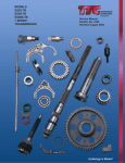
HYDRAULIC KIT INSTRUCTIONS FOR FORD AND MOPAR TKO, RS, T56, MAGNUM, & T45RS BEFORE INSTALLING TRANSMISSION IN CAR, YOU MUST CHECK THE HYDRAULIC BEARING CUSHION MEASUREMENT!!! SEE PAGE 8 OF INSTALLATION MANUAL FOR INSTRUCTIONS ON MEASURING HYDRAULIC BEARING CUSHION. RECORD THIS MEASUREMENT FOR FUTURE REFERENCE. MAM-00201 FORD & MOPAR Hydraulic Manual, Rev B 08/26/14 DAMAGE WILL OCCUR IF MEASUREMENT IS INCORRECT!!! The material herein is the intellectual property of Silver Sport Transmissions (“SST”) and is to be used by SST customers or their authorized installers for the sole purpose of installing SST-supplied transmissions and related parts. Under no circumstances shall the manual or any portion thereof be copied, duplicated, distributed or incorporated in any written or printed document without the express written approval of Silver Sport Transmissions. SYSTEM DESCRIPTION: This system uses a firewall-mounted hydraulic master cylinder with remote reservoir and a combination slave cylinder/release bearing assembly. This combination bearing is called a concentric slave cylinder (CSC) and it is designed to be in constant contact with the pressure plate fingers. The CSC is compressed by the pressure plate fingers when at rest. When the clutch pedal is depressed, the master cylinder forces fluid into the CSC, causing it to expand and depress the pressure plate fingers, thereby releasing the clutch. This system works best with DOT 4 brake fluid, even though the reservoir lid says DOT 3. DO NOT use DOT 5 brake fluid! The seals in the CSC are not compatible with DOT 5 fluid, and will be ruined on contact with it. We recommend using a high-performance, extra-hightemp name brand DOT 4 brake fluid from ATE, Wilwood, or others. This system is engineered for use with a diaphragm-style pressure plate and is not compatible with some three-finger style pressure plates. It is recommended that you remove the over-center spring (if equipped) from the clutch pedal when using a diaphragm-style pressure plate. KIT CONTENTS Please confirm that all parts have been received. The parts contained in your Master Cylinder kit vary by car model, and will include: - fluid reservoir, hose, and fittings - mount block, backing plate and gasket - pushrod extension - rod end and pedal attachment hardware - master cylinder - hardware NOTE: PARTS PICTURED ARE ONLY EXAMPLES. THE CORRECT PARTS FOR YOUR PARTICULAR VEHICLE MAY NOT LOOK THE SAME. The parts contained in your Slave Cylinder kit are: - transmission front bearing retainer - Concentric Slave Cylinder (CSC) - braided steel hose with bleeder - 5/16”-18 flat head socket cap screws (4) - 1/4”-20 hex head bolts (2) - 1/4” lock washers (2) - spacer plates (if required for application) If the hydraulic kit was ordered at the same time as the transmission, then your CSC will already be mounted on the front of the transmission. 2 MAM-00201 FORD & MOPAR Hydraulic Manual, Rev B 08/26/14 DISASSEMBLY Remove original clutch linkage, transmission and bellhousing components: Fork push rod, clutch pedal push rod assembly Z-bar retaining clip, Z-bar Drive shaft Shifter handle and shift mechanism (if 3 or 4-speed equipped) Transmission, bellhousing Throw-out bearing, clutch fork, fork boot, fork pivot bracket Ball studs/bracket assembly INSTALLATION OPTIONS The SST hydraulic system may be installed and then bled on the vehicle in the conventional manner, or it may be assembled off the car for bench bleeding, and then installed on the vehicle as a complete unit. If you choose to bench bleed the system and install as a complete unit, please go through the complete installation procedure as described below to ensure proper fitment of all parts BEFORE bench bleeding. Once you are satisfied that all the parts are installed correctly, you may remove the master cylinder and reservoir from the firewall and the CSC from the transmission, and then begin the bench bleed procedure. MASTER CYLINDER MOUNTING 1964-up Mustangs with power brakes may have interference between the power brake booster and the clutch master cylinder. If you find that to be the case on your car, Stangaholics has brake boosters that will work with our hydraulic clutch system. Contact them at 1-559-535-5669 or visit their website at http://stang-aholics.com. Some Mopar A-Bodies will run into interference between the clutch master cylinder and the left inner fender. If this occurs, the inner fender will have to be modified to create clearance for the clutch master cylinder. 1. From under the hood, locate the factory clutch pushrod hole. On automatic cars, this will be an oval or round hole with a rubber grommet or a metal knockout. Some vehicles may not have a factory hole in the firewall, but there should be a spot that is contoured for a hole. That spot is usually located below and slightly to the left (driver’s side) of the brake master cylinder or brake booster mount, near the steering column. 2. If no clutch rod hole exists in your firewall, measure the diameter of the pushrod hole in the clutch master cylinder mounting block (the side that is against the firewall). Cut a hole of that size in the factory spot on the firewall. Some cars may require elongating the hole due to the angle of the master cylinder. 3 MAM-00201 FORD & MOPAR Hydraulic Manual, Rev B 08/26/14 3. From the engine compartment, insert the master cylinder pushrod through the firewall and center the master cylinder pushrod in the hole, keeping the mount block against the firewall. Confirm that the pushrod points toward and reaches the clutch pedal attachment point (see “PEDAL ATTACHMENT” section). Carefully mark the firewall for each of the mounting bolt holes using a transfer punch, center punch or marker. Alternately, you can use the master cylinder backing plate to mark the inside of the firewall (make sure the backing plate is facing the right direction!) 4. The master cylinder must be positioned so that the pushrod moves in and out in a straight line. The master cylinder will not tolerate a side load, and will wear out very quickly if the pushrod is going in at an angle. Make sure the pushrod is straight in line with the master cylinder! 5. Drill a 3/8” diameter hole through the firewall for each marked location. Remove burrs. 6. Assemble mount block gasket to mount block, then set the master cylinder and mount block assembly to the firewall. Assemble 5/16”-18 bolts through the assembly and firewall. On some applications it may be necessary to insert one or more bolts (usually the bottom bolt) from the passenger compartment side of the firewall. 7. From passenger compartment, install backing plate, lock washer and nuts onto master cylinder. Align master cylinder, then tighten nuts to 15 lb.-ft. 8. Assemble the 90° end of the braided steel line to master cylinder port closest to firewall. 9. Assemble barb fitting to master cylinder at port located furthest from firewall. Use caution not to over tighten and break fittings. 10. RUBBER PLUG DRILL MOUNTING HOLES TO MATCH MOUNT BLOCK AND BACKING PLATE 4 MAM-00201 FORD & MOPAR Hydraulic Manual, Rev B 08/26/14 Typical Master Cylinder Assembly: ADJUST TO CORRECT PEDAL POSITION LINE FROM RESERVOIR LINE TO CLUTCH SLAVE CYLINDER MASTER CYLINDER BACKING PLATE ATTACH TO CLUTCH PEDAL MOUNTING BLOCK GASKET FIREWALL NOTE: If you are also installing a SST transmission that requires a new speedometer cable, now is a really good time to install the new cable. FLUID RESERVOIR MOUNTING 1. Assemble reservoir to the bracket using hardware supplied (part # CAA-PACK A). 2. The reservoir assembly may then be attached to the firewall, inner fender, or brake master cylinder mounting points. The reservoir must be higher than the clutch master cylinder and should be level. SLAVE CYLINDER MOUNTING If your hydraulic clutch system was ordered at the same time as your transmission, the CSC will be mounted on the front of your transmission and you can proceed to the next section “HYDRAULIC BEARING CUSHION MEASUREMENT”. If it was ordered separately, you will need to mount the CSC onto the transmission following the procedure outlined here. 5 MAM-00201 FORD & MOPAR Hydraulic Manual, Rev B 08/26/14 NOTE – TKO: This procedure involves removal of the transmission’s front bearing retainer and replacement with SST’s custom bearing retainer. DO NOT allow the input shaft to fall out, roller bearings may then fall into the transmission case, requiring transmission disassembly for removal! NOTE – RS, T56, Magnum, and T45RS: On these transmissions, the “bearing retainer” is solely used as a mount for the CSC. It is completely external to the transmission and does not contain the input shaft bearing. 1. ALL: Remove four (4) bolts holding the front bearing retainer to the transmission. (FIG. A) 2. ALL: Remove the front bearing retainer by tapping lightly with a mallet to break it free. TKO: Be sure to keep pressure on the input shaft or it may fall out. (FIG. B) 3. TKO: If the bearing race came out with the bearing retainer, remove it from the old bearing retainer and insert it into the transmission, taking care not to lose or damage the input shaft shims that are between the bearing retainer and the bearing race. (FIG. C) 4. If the race stayed in the transmission, be sure to remove the shims from inside the old bearing retainer. Clean old sealant from the front of the transmission case using a razor blade scraper. 5. TKO: Place shims into new bearing retainer, using petroleum jelly to hold them in place. (FIG. E) FIG. A REMOVE BOLTS FIG. B REMOVE OLD RETAINER FIG. D (TKO ONLY) INSTALL BEARING RACE IN TRANS FIG. C (TKO ONLY) REMOVE BRG. RACE AND SHIMS FIG. E (TKO ONLY) INSTALL SHIMS IN NEW RETAINER 6. TKO: Following manufacturer directions, spread a THIN coat of Permatex® Ultra Grey RTV Silicone Gasket Maker #82194 or equivalent on the mounting face of the new bearing retainer. 7. ALL: Position the new bearing retainer so that the two CSC bolt holes in the retainer are at the top and the lower passenger side of the transmission, and attach to the transmission using four socket head cap screws (FIG. G). TKO: Ensure that the oil galley hole located at 12 o’clock lines up with the cutout in the bearing retainer (FIG. F AND FIG. G) 8. ALL: Torque the fasteners to 12-16 lb.-ft. in an “X” pattern. 9. TKO: Make sure that the input shaft still turns and does not have any perceptible fore-and-aft movement. If it does not rotate or has excessive end play, shim per Tremec instructions. The service manual is a free download from Tremec’s website at: http://www.ttcautomotive.com/English/onlineorder/product.asp#Service%20Manuals (manual # LD35-0510-0199, TR-3350 & TKO) 6 MAM-00201 FORD & MOPAR Hydraulic Manual, Rev B 08/26/14 Printed manuals are available for purchase through Silver Sport Transmissions or Tremec. Silver Sport Transmissions also has shims available if needed. FIG. F INSTALL NEW RETAINER FIG. G RETAINER PROPERLY INSTALLED CSC MOUNT HOLES 10. ALL - Install ¼” CSC spacers (if required) over the input shaft and against the bearing retainer, according to these guidelines (you may need to add or subtract spacers later): Mopar RS & TKO – install (2) spacers Ford RS, TKO & T45RS with long (6.9”) input shaft – install (2) spacers Ford RS, TKO & T45RS with short (6.5”) input shaft – NO spacers T56 and Magnum – As required, see “HYDRAULIC BEARING CUSHION MEASUREMENT” below to determine if spacers are needed. The holes in the spacers will only line up one way with the holes in the bearing retainer. NOTE: The “HYDRAULIC BEARING CUSHION MEASUREMENT” described below MUST be taken for ALL APPLICATIONS. The guidelines above are only to give you a starting point. There are too many different combinations of clutches, flywheels and bellhousings for these guidelines to be correct in all situations. DAMAGE WILL OCCUR to the release bearing or the clutch if the cushion measurement is not taken and the wrong number of spacers are used. 11. ALL: Slide Concentric Slave Cylinder (CSC) over input shaft. (FIG. H) 12. ALL: Position CSC so that the hydraulic inlet points towards the fork opening in your bellhousing. Attach CSC using (2) supplied ¼”-20 x ¾” hex bolts and lock washers (torque to 5 ft/lbs). You will only use the 2 ears located at the top and on the lower passenger side, the third one is not used. 13. ALL: Continue with the remainder of your hydraulic clutch kit installation. FIG. H INSTALL SPACERS (IF NEEDED) AND CSC FIG. J CSC PROPERLY INSTALLED 7 MAM-00201 FORD & MOPAR Hydraulic Manual, Rev B 08/26/14 HYDRAULIC BEARING CUSHION MEASUREMENT The CSC is designed to be compressed by more than ½” by the pressure plate fingers when at rest. The CSC needs a minimum of 1/8” cushion beyond that to allow for clutch disc wear and expansion from heat. Clutch slippage will result if the CSC bottoms out and is partially depressing the pressure plate fingers at rest. The cushion measurement procedure below tells you how far the CSC is away from being completely bottomed out. The acceptable range for the CSC cushion is between 1/8” (0.125”) and 3/8” (0.375”). 1. With the correct clutch pressure plate and clutch disc mounted and torqued to the flywheel, install the bellhousing to the engine. 2. Use a straight edge and a steel rule to measure from the transmission mounting face of the bellhousing to the surface of the clutch fingers that contacts the release bearing. Record this depth measurement ( X ). THIS PHOTO SHOWS 3 - 9/16” DEPTH (X) X 3. Next, with the slave cylinder mounted on the transmission, compress the CSC against its internal spring pressure back towards the transmission. With the CSC compressed to its internal stop (completely bottomed out), hold a straight edge across the face of the throw-out bearing and measure the distance from the face of the bearing to the bellhousing mounting face of the transmission. Record this dimension (Y). Y MEASURE FROM THE FRONT OF THE TRANSMISSION CASE TO THE SURFACE OF THE FULLY COLLAPSED BEARING FOR YOUR “Y” DIMENSION. THIS PHOTO SHOWS 3-5/16” WITH 2 CSC SPACERS INSTALLED. BEARING FULLY COLLAPSED 8 MAM-00201 FORD & MOPAR Hydraulic Manual, Rev B 08/26/14 4. Your depth measurement ( X ) minus the compressed bearing height ( Y ) is your bearing cushion. ( X ) – ( Y ) = CUSHION 5. The resulting cushion dimension should be at least 1/8” (0.125”), but no more than 3/8” (0.375”). Anywhere within this range is acceptable. There is no advantage or disadvantage to being at the upper or lower end of the range, or even in the middle. The CSC will function exactly the same way, no matter where it lies within this range. 6. If your cushion is less than 1/8”, you will need to remove one or more CSC spacers from behind the CSC in order to achieve the desired measurement. Shorter bolts (1/4”-20) will be required. If your combination did not include any spacers, or if removing all of the CSC spacers still does not put you in range, Silver Sport Transmissions has a 1/4” thick bellhousing spacer available that gets sandwiched in between the bellhousing and the transmission case. Please call Silver Sport Transmissions to order a bellhousing spacer. 7. If your cushion is greater than 3/8”, call Silver Sport Transmissions to order extra CSC spacers to achieve the correct cushion measurement. Recheck the ( Y ) measurement and calculate your new cushion measurement after adding or removing CSC spacers. CSC SPACER BELLHOUSING SPACER ***** NOTE: The bearing cushion will also need to be re-measured and recalculated after resurfacing or replacing the flywheel, or changing the bellhousing, engine, or clutch. Different clutches have different stack-up heights, and a scattershield is often deeper than a factory bellhousing. Damage will result from an incorrect cushion dimension! TRANSMISSION MOUNTING 1. Remove bellhousing from engine and install bellhousing to transmission. Tighten bolts only lightly at this time. 2. Install the metal fork hole cover and grommet onto the end of the braided steel line that has the bleeder screw on it. Insert that end of the line through the bellhousing fork hole and attach braided steel line to CSC, being very careful not to cross-thread the fitting. The line is designed for the bleeder screw to point downwards in order to reduce the chance of brake fluid getting on painted surfaces on your car during the bleeding process. Place grommet (from part # CAA-PACK C) over the other end of the braided steel line. 3. Verify the braided steel line is towards the back of the bellhousing and away from rotating components. 4. The transmission, bellhousing, and hydraulic throw-out bearing are installed as a unit to the engine. 9 MAM-00201 FORD & MOPAR Hydraulic Manual, Rev B 08/26/14 HYDRAULIC LOW PRESSURE HOSE MOUNTING 1. Run the rubber supply hose from the bottom of the reservoir nipple to the barb fitting in the clutch master cylinder, and determine the exact length for the supply hose. The hose should be neither tight nor excessively loose, and should clear all moving steering gear and exhaust components. Take care to prevent foreign debris from entering hose. 2. Cut the line to the desired length, ensuring that no foreign matter is in the hose. Then, loosely assemble hose clamps. 3. Install hose to the master cylinder, then to the reservoir. When installing hose to the reservoir, hold the top of the reservoir to prevent overloading and damaging the mounting ears. HYDRAULIC HIGH PRESSURE HOSE MOUNTING 1. After bolting the transmission/bellhousing unit to the engine, install the grommet for the line support bracket (if used) onto the master cylinder end of the pressure line. Attach the remaining end of the braided steel line to the clutch master cylinder and tighten. Use caution not to over tighten and break the fitting. 2. The line support bracket (part # CAA-PACK C) may be installed now if needed to keep the braided steel line away from your exhaust. The support bracket is designed so that it can be held by one of your bellhousing-to-engine bolts, one of the threaded holes on the side of the bellhousing, or it may be attached to your frame or firewall depending on application. See photo below. LINE SUPPORT BRACKET 3. Final tighten all transmission mounting bolts (4 pcs). 4. Inspect the supply line inside the bellhousing and confirm the hoses have ample clearance to the rotating clutch plate. It is extremely important that the hydraulic clutch hose DOES NOT come into contact with the clutch plate, as serious damage could result. NOTE: DOT 4 BRAKE FLUID STRONGLY RECOMMENDED, (even though the lid says DOT 3). SHIELD HYDRAULIC LINES FROM HEAT, ESPECIALLY NEAR EXHAUST HEADERS. PEDAL ATTACHMENT NOTE: If you are changing from a 3 finger style pressure plate to a diaphragm style pressure plate you should also remove the clutch pedal over center spring, if equipped with one. Failure to remove the over center spring could result in the spring holding the clutch pedal down during normal operation. The over center spring will also tend to hold the pedal down while performing the bleeding operation, until the system is bled enough to return the pedal. An over center spring is not recommended for use with a diaphragm-style pressure plate, and the hydraulic system is not compatible with some 3 finger style clutches. We strongly recommend a diaphragm-style pressure plate. 10 MAM-00201 FORD & MOPAR Hydraulic Manual, Rev B 08/26/14 Shoulder Bolt Attachment (uses part # CAA-PACK F) 1. If there are two possible attachment holes in your clutch pedal arm, in most cases you will use the hole that the factory original pushrod would have used. If you are not sure which hole this is, please consult a factory service manual. Otherwise, use the hole that best lines up with the pushrod coming out of the master cylinder. On some applications, the pushrod actually connects to a bracket that is welded or bolted onto the pedal. Again, consult a factory service manual if needed. 2. Adjust rod end position to achieve proper pedal height with master cylinder clutch push rod EXTENDED ALL THE WAY OUT. If the master cylinder is not fully extended when the pedal is at rest, the master cylinder can be difficult to bleed, and SHOULDER BOLT TYPE can overextend the CSC and cause it to fail. Make sure the pushrod travels in and out of the master cylinder in a straight line and does not contact the firewall, mount block, or backing plate at any point during its travel. When desired pedal height is achieved, tighten the jam nuts on the pushrod and rod end. 3. Assemble shoulder bolt through rod end on master cylinder pushrod. 4. Assemble aluminum spacer sleeve to shoulder bolt, if needed. It may go in between the rod end and clutch pedal OR on opposite side of clutch pedal from the rod end, if it lines up better when it is against the pedal. Tighten to 6 lb.-ft. 5. Note: You may have to loosen the brake light switch bracket to insert the bolt. In some applications, a small adjustment of the switch position may be required to clear the bolt head. 6. DO NOT pump the pedal until fluid is added to the reservoir. DOT 4 BRAKE FLUID STRONGLY RECOMMENDED. NOTE: On some MOPAR applications, you will need to remove the stud that the original pushrod attached to, and then use our shoulder bolt in that hole. Remove the stud by grinding off the weld and driving it out of the clutch pedal. CLEVIS TYPE Clevis-type Attachment 1. Adjust rod end position to achieve pedal in home position with clutch push rod fully extended, as described in Step 2 of the “Shoulder Bolt Attachment” section above. 2. Install rod end, flat washer, then spring clip retainer or cotter pin. HYDRAULIC FLUID FILL & BLEED – ON CAR If you have chosen to bench bleed the system and install as a unit, please skip to the next section. You will need two people to bleed this clutch system when installed on the vehicle. Use caution to prevent brake fluid from contacting paint, as damage will likely occur. If your vehicle has an over-center spring installed, it will tend to hold the clutch pedal to the floor until the system is bled enough to return the pedal itself. Remove reservoir cap and baffle from the reservoir. 11 MAM-00201 FORD & MOPAR Hydraulic Manual, Rev B 08/26/14 1. Fill the reservoir full with DOT 4 brake fluid. During the next steps check regularly to make sure that the reservoir does not run out of fluid. If this happens you will have to start the process over. 2. Open the bleeder screw to allow air to escape from the system. Give the fluid a few minutes to make its way down to the bleeder screw, while watching the fluid level in the reservoir and refilling as necessary. Allow fluid to drip from the bleeder screw into a suitable container. 3. It may be necessary to prime the master cylinder by removing the high pressure hose at the master cylinder and block the fitting outlet to draw fluid into the cylinder when stroking the pedal. When the cylinder is primed, reattach the pressure line and continue the bleeding procedure. Take care not to spill brake fluid on any painted surfaces. 4. When the drip becomes a steady stream, close the bleeder screw. Refill the fluid reservoir. Open the bleeder screw slightly and have your helper depress the pedal slowly. Close the bleeder as soon as the pedal reaches the floor. Then have your helper slowly release the pedal. Pressing or releasing the pedal too quickly will cause brake fluid to squirt from the top of the reservoir. The pedal may need to be manually pulled up from the floor during these steps. Repeat this process several times, refilling the reservoir every 3 strokes or so. 5. When the bleeder stops spitting air, close and tighten the bleeder screw. Pump the pedal several times to check for proper feel. Repeat the process if the pedal is not firm throughout its travel, or if it seems that the clutch is not releasing fully. Make sure that the master cylinder pushrod is traveling its full stroke of 1.4” and that the master cylinder is fully extended when the clutch pedal returns to its home position (no tension on the pushrod with the clutch pedal all the way up). 6. VACUUM BLEEDING PROCEDURE: If bleeding proves difficult for one reason or another, a manual vacuum bleeder can be used to draw a vacuum on the reservoir and thereby the entire system and pull trapped air into the reservoir. With the rubber baffle removed from the reservoir and the cap installed, apply vacuum to the vent hole in the center of the cap. You may try stroking the pedal while vacuum is being applied. Repeat until the system is bled. It may take 20-30 minutes or even more in order for the vacuum method to get all the air out of the system. 7. Upon successful bleeding, fluid level will need to be lowered to approximately 1/3 full. Excess fluid may be removed from the reservoir by siphoning with a hand-held vacuum pump or with a spoon or medicine cup. Reinstall rubber baffle and cap. 8. Inspect for leaks, and replace the bellhousing inspection cover. 9. Check fluid level and add if necessary after the first test drive or after vehicle sits overnight. NOTE: It may be necessary to bleed the clutch again after minimal use, as operation may dislodge some trapped air. OPTION: BENCH BLEED PROCEDURE Do not begin bench bleed procedure unless you have already temporarily installed ALL of the hydraulic kit parts onto the vehicle for test fitment. 1. Leaving both hoses attached to the master cylinder and reservoir, and the mount block attached to the firewall, remove master cylinder from mount block and reservoir from firewall. 2. In order to be able to install the system as a unit, the master cylinder and hose assembly must be able to pass through the fork hole opening in the bellhousing. Test this to make sure it will work on your bellhousing. It may be necessary to loosen the braided steel line slightly, just enough that the line itself can be rotated at the master cylinder to allow the assembly to fit through the fork hole. If you must rotate the line slightly, make sure you tighten it in this position before starting the bleeding procedure. 12 MAM-00201 FORD & MOPAR Hydraulic Manual, Rev B 08/26/14 3. Remove CSC from transmission. 4. Secure lower ear of master cylinder in a vise. Position master cylinder so that you will be able to push on the pushrod. 5. Temporarily attach the reservoir to anything you have available that will support the reservoir and keep it upright. You may use a C-clamp to attach it to an open cardboard box or a trash can, for instance. Make sure the reservoir is higher than the master cylinder. 6. The CSC must be prevented from over-extending while you are bleeding the system. You may use a C-clamp, bar clamp, handscrew clamp, etc. to restrict the CSC from extending too far. Place the bearing right side up between two wooden blocks and clamp them in place (see photo below). During this step, compress the CSC by hand once until it bottoms out. When you let go of the CSC, the bearing portion (the outer part that you can see) will return to the fully extended state due to internal spring pressure, but the hydraulic piston will remain fully compressed inside the CSC. 7. Attach the braided steel line to the CSC in the correct orientation, with the bleeder pointed downwards. Loosen the bleeder screw. 8. Make sure that the reservoir is higher than the master cylinder, and that the master cylinder is higher than the CSC. MASTER CYLINDER AND RESERVOIR MOUNTED FOR BENCH BLEEDING CSC WITH CLAMP 9. Fill the reservoir with clean, new DOT4 brake fluid from a sealed container. With the bleeder screw loosened, fluid will make its way down through the system and start to run out of the bleeder screw. Be sure to keep fluid in the reservoir. When you start to get a steady stream of fluid from the bleeder screw, close the bleeder. 10. Refill the reservoir with DOT4 brake fluid. Connect a clear ¼” I.D. fluid line (such as from a vacuum bleeder kit) to the bleeder screw. Place the other end in the reservoir and secure the hose with a wire to make sure it doesn’t come out of the reservoir. 11. Locate a shifter ball, block of wood, or other suitable item to use as a handle to depress the pushrod. Make sure you are pushing it straight in. Crack open the bleeder screw, and slowly depress the master cylinder pushrod until it bottoms out. Close the bleeder, and then slowly let the pushrod return to the fully extended state. Moving the pushrod too quickly will cause brake fluid to squirt from the top of the reservoir. Do this 3 - 4 times, making sure that the reservoir does not run out of fluid. 12. Repeat until you stop getting air out of the bleeder. 13 MAM-00201 FORD & MOPAR Hydraulic Manual, Rev B 08/26/14 13. Once you stop seeing air bubbles come from the bleeder, crack the bleeder open and then compress the CSC again until it bottoms out. Close the bleeder. Verify that the CSC is securely clamped, and then stroke the master cylinder several times until you feel resistance. Resistance means that the hydraulic piston in the CSC is at the end of its travel, and cannot move any further due to the clamp. 14. If the system is fully bled at this point, you will not be able to depress the master cylinder pushrod more than 1/8” or so with the bleeder closed and the CSC clamped. If the master cylinder pushrod feels spongy or you can move the pushrod in by more than about 1/8”, then repeat steps 11 through 13 until you are satisfied that all air has been removed from the system. 15. Remove most of the fluid from the reservoir. With the bleeder closed, slowly compress the CSC one more time until it bottoms out. The CSC internal hydraulic piston needs to be completely bottomed out in order to install the transmission. This will displace fluid back up through the system and into the reservoir. Remove the clear fluid line from the reservoir and disconnect from the bleeder. Remove fluid again so that the reservoir is about 1/3 full. 16. Install the reservoir baffle and cap. 17. Remove the clamp from the CSC. 18. Disconnect the reservoir from the master cylinder, and remove the master cylinder from the vise. 19. From inside the bellhousing, thread the reservoir, the master cylinder, the braided steel fluid line and the fork hole cover (if used) through the clutch fork opening in the bellhousing. 20. Install the CSC onto the front of the transmission. See “SLAVE CYLINDER MOUNTING” section above. Torque CSC retaining bolts to 5 lb.-ft. 21. Continue transmission installation. Re-install master cylinder and reservoir onto firewall, and connect pushrod to pedal as described in “PEDAL ATTACHMENT” section above. Re-position and retighten master cylinder pressure line if it was rotated in order to fit through bellhousing fork hole. 14 MAM-00201 FORD & MOPAR Hydraulic Manual, Rev B 08/26/14 INSPECTION AND TESTING USE EXTREME CAUTION WHEN TESTING CLUTCH RELEASE SYSTEM. DO NOT TEST IN HIGH TRAFFIC OR PUBLIC AREAS. ENGINE OFF TEST Parking brake set, test the release and engagement of the clutch mechanism. Check for the following: 1. Clutch pedal completely up at its home position when released, and that the master cylinder pushrod is fully extended when the pedal is all the way up. 2. Clutch pushrod does not hit brake light switch bracket or anything else under dash. 3. Low resistance for initial travel when depressing clutch pedal. Clutch resistance increasing at 1/3 of full stroke and remaining approximately constant through full travel to the floor. 4. Clutch pedal travel to floor without over-travel of clutch plate. Over-travel is characterized by a sudden hard pedal. This should not be a problem if the “Hydraulic Bearing Cushion Measurement” was accurately made and is within spec. 5. Clutch pedal travel to floor without hydraulic bearing extending to its travel stop. Extending to the travel stop is characterized by a sudden high pressure required to exert further pedal stroke. If this condition occurs, damage to the master cylinder seals or slave cylinder will result from continued operation. This also will not be a problem if the “Hydraulic Bearing Cushion Measurement” was performed properly and is within spec. NOTE: The hydraulic slave cylinder has slightly over 7/8 inch total stroke, minus the cushion that was measured earlier. Most clutches release within 1/2 inch travel. 6. Smooth system operation with no abnormal noises. ENGINE ON TEST Hold brake, place transmission in neutral, start engine. Achieve idle of 1000 rpm or less. 1. Depress clutch pedal. 2. Ease shifter into first gear. CAUTION: If grinding occurs, pull back to neutral and stop engine. Repeat bleeding process and verify that the master cylinder pushrod is moving a full 1.4”. 3. Slowly release clutch pedal while maintaining brake pedal pressure. Confirm engine is being loaded as clutch pedal is released. 4. Repeat test step 1-3 through all gears, including reverse. NOTE for TKO ONLY: Reverse is not synchronized in the TKO 5-speed, and grinding may occur. This can be eliminated through placing shifter in a forward gear immediately before proceeding to reverse. 15 MAM-00201 FORD & MOPAR Hydraulic Manual, Rev B 08/26/14 CARE AND MAINTENANCE Your SST hydraulic clutch actuator system is designed to give you years of trouble-free service. In order to maximize the life of the system: Periodically check fluid level, hose clamps and hoses for damage. Flush hydraulic fluid every 2 years with new, clean DOT 4 brake fluid. SYSTEM SPECIFICATIONS Master cylinder: Bore = 0.750” Stroke = 1.400” CSC: Stroke = .910” Fluid: DOT 3 brake fluid is acceptable, DOT 4 strongly recommended. DO NOT USE DOT 5 FLUID. ACCESSORY ITEMS The following accessory items will enhance your vehicle installation: SST Cast Titanium-Aluminum Bellhousing. New casting features super high strength aircraft alloy, lightweight, precision CNC machining for accurate alignment of transmission to crank bore. Both 4speed & 5-speed versions are available. Clutches/Flywheels – We carry a full range of clutches, and both billet steel and aluminum flywheels. SST Reproduction Pedal Assemblies – New precision-made pedal conversion allow easy conversion from automatic, or quality replacement parts for restoration. Shifter Handles – Full line of 4, 5, and 6-speed shifter handles, pistol grips, and shift balls. CONTACT INFORMATION SILVER SPORT TRANSMISSIONS 2250 STOCK CREEK BOULEVARD ROCKFORD, TENNESSEE 37853-3043 Phone: (865) 609-8187 Toll Free: (888) 609-0094 Fax: (865) 609-8287 SALES EXTENSION: 113 CUSTOMER SERVICE AND TECH SUPPORT EXTENSION: 118 WWW.SHIFTSST.COM SILVER SPORT TRANSMISSIONS IS DEDICATED TO YOUR SATISFACTION AND ENJOYMENT OF THIS PRODUCT. PLEASE SEND US PICTURES OF YOUR CAR ALONG WITH A TESTIMONIAL OF HOW YOU RATE THIS PRODUCT. WE WILL BE POSTING MANY CUSTOMER FEEDBACK LETTERS AND PICTURES ON OUR WEBSITE AND BROCHURES. ENJOY YOUR SILVER SPORT TRANSMISSION SYSTEM! 16 MAM-00201 FORD & MOPAR Hydraulic Manual, Rev B 08/26/14 TROUBLESHOOTING GUIDE If you are having any sort of problem with the hydraulic system, the first step is to review the “Hydraulic Bearing Cushion Measurement” procedure starting on page 7, and verify that you have the correct amount of cushion (1/8” – 3/8”). Do this before going ANY further into the installation. DIFFICULTY BLEEDING, FLUID WILL NOT FLOW, CAN’T GET ALL THE AIR OUT, CLUTCH WON’T FULLY RELEASE: Review the bleeding procedure. Verify: - That the master cylinder pushrod is fully extended when the clutch pedal is all the way up. If there is any tension on the pushrod and the pushrod does not come all the way out, it can close off the fill port in the master cylinder, and fluid will not be able to flow from the reservoir to the master cylinder. This condition can also cause the CSC to overextend and fail. -That you are getting a full 1.4” (1-3/8”) of stroke out of the pushrod itself. If not, then the pushrod extension may need to be adjusted, the master cylinder may need to be repositioned on the firewall, or it may be that the pushrod needs to be connected to a different spot on the pedal. If you change the mount position or connection point, make sure that the pushrod still ends up traveling in a straight line into the master cylinder. - Make sure the firewall is not flexing. If you measure at the pedal arm and the pushrod is moving 1.4”, but the firewall is flexing 0.250”, then you are actually only getting 1.15” of stroke. - If you are using a reservoir that did not come from us, make sure the lid is vented. Some aftermarket reservoirs do not have a vented lid, and this will prevent the system from self-adjusting or bleeding properly. - If you are using a master cylinder that didn’t come from SST, it may be too small. Any master cylinder you use must displace nearly the same amount of fluid as ours in order for it to work properly. Our master cylinder has a 0.750” bore and a 1.4” stroke. If you go with a larger diameter bore, it will INCREASE the amount of pedal effort required and require a shorter stroke; a smaller bore will DECREASE the pedal effort, but require a longer stroke. - A master cylinder with a 5/8 (0.675)” bore needs a 2.1” stroke to be compatible with our CSC - A master cylinder with a 7/8 (0.875)” bore needs a 1.1” stroke to be compatible with our CSC - Other, non-hydraulic problems can prevent the clutch from releasing. If the clutch disc is too large in diameter for the pressure plate, it could be pinched. The tip of the input shaft could be bottomed out in the crankshaft. The clutch disc could have gotten contaminated and could be stuck to the pressure plate or flywheel. The pilot bearing could be frozen. HIGH PEDAL EFFORT - The most common cause for a high pedal effort is having the pushrod connected too low on the pedal. Moving the pushrod connection point up closer to the pedal pivot point will reduce the pedal effort. Doing this may also require that the master cylinder be repositioned. - If the pushrod is not straight in line with the master cylinder, that will also cause increased pedal effort and will wear the master cylinder prematurely. - Make sure there are no kinks in the braided steel line. 17 MAM-00201 FORD & MOPAR Hydraulic Manual, Rev B 08/26/14 BLACK FLUID - If the fluid in the system turns black or has debris in it, that typically means that the pushrod is not straight with the master cylinder. If the pushrod is at an angle to the master cylinder, this will cause the master cylinder to wear prematurely, and the black specks are actually oxidized aluminum particles. CLUTCH WON’T DISENGAGE WHEN HOT, PEDAL GETS SPONGY - If the fluid gets too hot, it can boil and create bubbles in the system. Route hydraulic lines as far away from the exhaust as possible, and shield them if needed. Make sure you are using fresh hi-temp DOT4 brake fluid in the system. Brake fluid that has been sitting on the shelf for a long period of time will absorb moisture from the atmosphere, even if the container is closed. Moisture in the fluid can lower the boiling point significantly. CLUTCH SLIPS OR DISENGAGES PREMATURELY - You may be “upside down” on the hydraulic bearing cushion measurement. If your “X” measurement is smaller than your “Y” measurement, this will give you a negative cushion, and the pressure plate fingers are actually being depressed all the time. Double check your hydraulic bearing cushion measurements and your math. CSC FAILURE, CSC LEAKING FLUID, CSC HAS COME APART - Your hydraulic bearing cushion measurement is likely too big (greater than 3/8”) OR the master cylinder pushrod is adjusted too tight and is not allowing the master cylinder to return to the fully extended position. Recheck your cushion measurements and your math, as well as the pushrod adjustment. The CSC is not rebuildable. It is an OE part that we modify so that it will work with our transmissions. If you are still having issues, call Silver Sport Transmissions’ Customer Service and Technical Support at (865) 609-8187 extension 118. 18 MAM-00201 FORD & MOPAR Hydraulic Manual, Rev B 08/26/14