1
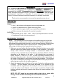
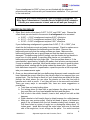
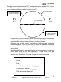
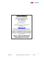
INSPECTION AND CORRECTION OF BELLHOUSING TO CRANKSHAFT ALIGNMENT BACKGROUND Proper alignment of the transmission input shaft to the crankshaft centerline is required in order to achieve the best results from your new transmission system. The relationship of the input shaft to the crankshaft is established by the bellhousing bore, and the bellhousing is located on the engine by the dowel pins in the back of the block. If the centerline of the bellhousing bore is not perfectly aligned with the centerline of the crankshaft, there is misalignment. Failure to stay within alignment limits can result in hard shifting, clutch engagement problems, and a worn pilot bearing, as well as accelerated wear in the transmission bearings and gears. Many engines and bellhousings were machined out of factory specification when new. Consequently, please do not assume a new or late-model engine is correct - it should be inspected using the procedure outlined below. Silver Sport CNC machines and quality checks our bellhousings for accuracy, but the overall assembly to your engine must be checked and corrected, as required by the specification below. The correction of misalignment, if found out of spec, is performed by removing the original factory dowel pins and replacing them with offset dowel pins. That procedure is covered later in this manual. MAA-00101 Alignment Inspection and Correction, Rev A 05/27/14 IMPORTANT !!! It is an absolute requirement that misalignment is checked and corrected PRIOR to installing the transmission. The misalignment specification for all of Silver Sport's conversion kits is 0.005" (5 thousandths of an inch) MAXIMUM misalignment. You MUST document the results PRIOR to installation of transmission and keep these measurements recorded in a safe place for your transmission warranty. Silver Sport’s Customer Service will need this information if a warranty issue arises. Thank you for your cooperation to ensure the required accuracy is met. PREPARATION TOOLS: One (1) dial indicator with magnetic base and adjustable arm Wrench or ratchet wrench to tighten bellhousing bolts Tool to rotate the engine, based on your particular combination Tools to remove old dowel pins if correction is needed SUPPLIES: Offset dowel pin set: 0.007", 0.014", or 0.021" (as required based on amount of misalignment found during measurement) MEASUREMENT PROCEDURE NOTE: The mounting faces of the engine and the bellhousing need to be clean and free of all dirt, oil and corrosion. It is also important to tighten the bellhousing bolts nearest the engine dowel pins first to ensure accurate readings. All bellhousing bolts must be installed and torqued to the proper level. Readings taken with the bellhousing not tightened down properly may not be accurate. 1. Make sure you are familiar with the operation of the dial indicator you are using and the direction the needle moves in relation to the movement of the probe. Identify which direction of sweep indicates a measurement closer to the centerline of the crankshaft. Some dial indicators will sweep different directions depending on the direction of the probe. A dial indicator has a set range of motion, such as 0 - 0.050” or 0 - 0.100”. In order to be able to measure in both directions, the probe needs to be pre-loaded so that the needle is somewhere in the middle of that range of motion when you start the procedure. This will allow the needle to sweep both clockwise and counterclockwise during the procedure, while staying in contact with the bellhousing bore. 2. Attach the magnetic base to the face of the crank, flywheel or stationary portion of clutch. The dial indicator base does not need to be centered on the crankshaft, and the magnetic base will usually be much more stable if mounted on the flat surface of the flywheel. As the engine is rotated by hand, the dial indicator and base will move in a perfect circle around the exact centerline of the crankshaft. NOTE: DO NOT install to any portion which might slip or move while testing, and do not allow measuring tool to touch the clutch fork. 2 MAA-00101 Alignment Inspection and Correction, Rev A 05/27/14 3. Position the indicator probe in contact with the smooth bore of the bellhousing that the transmission will fit into later. The dial indicator probe needs to be perpendicular to the bellhousing face to ensure accuracy. PROBE AT RIGHT ANGLE TO BELLHOUSING DIAL INDICATOR MAGNETIC BASE DIAL INDICATOR CRANK/FLYWHEEL ASSEMBLY Make sure the indicator has adequate travel in both directions and will be in constant contact with the bore register during the entire 360 degrees of rotation so that you will obtain accurate readings. It is not necessary to begin at a certain position on the bore, any point will work. Mark the point where you begin on the bellhousing with a hash mark using chalk or a marker as a reference. 4. Using a long bar on the front of the crankshaft, slowly rotate the engine in the direction of normal operation at least one full revolution while watching the dial indicator. A helper at this point is a really good idea! By watching the needle on your indicator, locate the point on the bellhousing bore that is the closest to the crank centerline. Mark that point on the bellhousing with a dot labeled “C” for closest. Set the dial indicator face to zero at this point. 5. Rotate the engine one full revolution while watching the dial indicator again. Make sure the dial indicator does not lift off the bellhousing bore or bottom out. The needle should sweep away from zero and should give you a peak measurement roughly straight across (180 degrees) from the point marked “C”. Record the measurement from your dial indicator at that maximum point and mark it with another dot. Continue rotating the engine back to your starting point “C” to make sure that the dial indicator returns to zero. It is recommended that the procedure be done twice to verify that the results are correct. Total Indicated Runout (T.I.R.) is the measured value you recorded opposite the closest point “C”. The amount of misalignment is equal to one-half the T.I.R. You must adjust your bellhousing if the misalignment is greater than 0.005" (T.I.R. > 0.010”). 3 MAA-00101 Alignment Inspection and Correction, Rev A 05/27/14 If your misalignment is 0.005” or less, you are finished with the alignment procedure and may continue with your transmission installation. If not, proceed to the next section. If you have any trouble determining if your alignment is acceptable, call Silver Sport Transmissions’ Customer Service at 865-609-8187 extension 118 with your measurements in hand, and we will walk you through it. CORRECTION PROCEDURE 1. Silver Sport stocks offset pins in 0.007”, 0.014”, and 0.021” sets. Choose the offset dowel pin set closest to the amount of misalignment to be corrected. a. 0.005” → 0.010” misalignment requires 0.007” offset pins b. 0.011”→ 0.017” misalignment requires 0.014” offset pins c. 0.018”→ 0.026” misalignment requires 0.021” offset pins If your bellhousing misalignment is greater than 0.026” (T.I.R. > 0.052”), first check the dial indicator mount and setup for movement. Check to make sure no wires are pinched between the bellhousing and the block. Remove the bellhousing and verify that the mating surfaces are clean. Make sure the bellhousing dowel holes are in good shape and that the dowel pins are not damaged. The bellhousing should fit snugly over the dowels and not be able to move once it is fully seated. If everything else checks out, re-install the bellhousing and install the bolts finger-tight. Then torque them down to ½ the manufacturer’s specification, following the pattern from a factory service manual. If none is available or specified, follow a star pattern such as you would do when installing a wheel, starting with the holes nearest the dowel pins. Once all the bolts have been torqued to ½ specification, repeat the process at full torque and take your measurements again. 2. Once you have determined that your bellhousing alignment needs correction and have obtained the correct offset pins, the old pins need to be removed from your engine block. The first thing to check is if your dowel holes are drilled all the way through the block where you can drive the dowels out from the front with a hammer and a drift or punch. If not, they will have to be removed from behind. There are many ways to accomplish this; here are some suggestions or possibilities: a. Twist them out using locking pliers. b. Put locking pliers on them with a gap between the pliers and the block face, and then use 2 pry bars between the block and the pliers. c. Drill a hole in the center, thread it, insert a bolt, and pull out with a slide hammer. d. Weld a bracket or bolt head to them to obtain leverage for a slide hammer. e. Make your own custom puller! Weld a bolt head or piece of all-thread to each of the old dowels with the bolt threads pointing back towards you. Drill three holes in a piece of angle iron or rectangular tubing about 1-2 inches apart. Install bolts through the outer holes, with nuts on the back side of the angle iron, to act as legs on the puller. You could use short 4 MAA-00101 Alignment Inspection and Correction, Rev A 05/27/14 pieces of rectangular tubing or steel rod as the legs if that is easier. Then assemble the new tool to the engine with the dowel pin bolt coming through the center hole. Thread a nut onto the dowel pin bolt, and as you tighten it the dowel pin should be pulled out. f. Heat may help. 3. Determine where the maximum offset is on each new pin by rolling the engine side of the dowel on a hard flat surface and looking for the maximum height point as it is being rolled. Mark the high spot with a dot from a paint marker or permanent marker. HIGH POINT MARK MAXIMUM GAP 4. Clean the dowel holes in the block and check the inside diameter with a pair of calipers. Then measure the outside diameter of the new dowel pins and compare. You want to tap the pins in and still be able to twist them with a very large screwdriver for fine-tuning of your alignment, but not have them loose enough that they will not stay in place. It is very important that the pins be sized correctly and the inside of the holes are clean and rust-free. Lubricate the inside of the holes with a small amount of penetrating oil once they are sized correctly. If the new pins are too loose, you can use an adhesive, sealant, RTV, or threadlocking compound to take up a small amount of extra space in the hole and hold the pins in place. Remember, once the new pins are oriented in the correct direction and the bellhousing bolts are tightened down, the bellhousing will not be able to move. 5. Install the pins into the rear of your engine block with the dot on the pins (maximum offset point) oriented in the same direction as the “C” mark on the bellhousing bore. Always orient both pins in the same direction! EXAMPLE: On the bellhousing below, the misalignment is such that the bore is closest to the crank at the upper left. The dial indicator would be set to zero at that point (labeled “C”). The T.I.R. would be measured where the bellhousing bore is furthest from the crank, which should be directly opposite that point. Let’s assume the T.I.R. reading is 0.034”. Actual misalignment would then be: 0.034” ÷ 2 = 0.017” 5 MAA-00101 Alignment Inspection and Correction, Rev A 05/27/14 The chart on page three shows that 0.017” misalignment requires a pair of 0.014” offset pins. The pins should be oriented so that their maximum offset is in the same direction as an imaginary line drawn from bore center to point “C”. SET DIAL INDICATOR TO ZERO WHERE THE BORE IS CLOSEST TO THE CRANK, AND LABEL IT “C” BELLHOUSING BORE C CENTER OF BELLHOUSING BORE LEFT PIN RIGHT PIN READ T.I.R. MEASUREMENT WHERE THE BORE IS FURTHEST FROM THE CRANK 6. Using a block, a drift, or something similar to protect the dowel pin face from the hammer, carefully tap the pins into place in the engine block. Make sure that the maximum offset mark you made is pointed in the correct direction. 7. Once the pins are fully seated, re-install your bellhousing and check the misalignment again. If it is not within spec, try turning the dowel pins so that the maximum offset dot you marked on the pin moves towards the new closest point, and re-check. 8. When the misalignment is within specification, you have completed a critical step in the proper setup of your new transmission. Please record your final measurements in the block below for future reference. In case of a possible warranty claim, Silver Sport’s Customer Service will need this information. Name: _____________________________ Date: ___________________ Initial Misalignment Measured: _________ Correction pins selected: ___________ Final Misalignment Measured: _________ 6 MAA-00101 Alignment Inspection and Correction, Rev A 05/27/14 CONTACT INFORMATION SILVER SPORT TRANSMISSIONS 2250 STOCK CREEK BOULEVARD ROCKFORD, TENNESSEE 37853-3043 Phone: (865) 609-8187 Toll Free: (888) 609-0094 Fax: (865) 609-8287 SALES EXTENSION: 113 CUSTOMER SERVICE AND TECH SUPPORT EXTENSION: 118 WWW.SHIFTSST.COM SILVER SPORT TRANSMISSIONS IS DEDICATED TO YOUR SATISFACTION AND ENJOYMENT OF THIS PRODUCT. PLEASE SEND US PICTURES OF YOUR CAR ALONG WITH A TESTIMONIAL OF HOW YOU RATE THIS PRODUCT. WE WILL BE POSTING MANY CUSTOMER FEEDBACK LETTERS AND PICTURES ON OUR WEBSITE AND BROCHURES. ENJOY YOUR SILVER SPORT TRANSMISSION SYSTEM! 7 MAA-00101 Alignment Inspection and Correction, Rev A 05/27/14