1
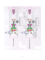
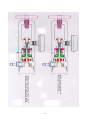
FLOTEC INC
7625 West New York Street
Indianapolis, IN 46214-4911
317-273-6960
(Fax) 317-273-6979
e-mail: [email protected]
web site: http://www.floteco2.com
Service Manual
RW Series
M-Service Manual RW Series Regulator(2014-07-31.docx.pdf
-1-
TABLE OF CONTENTS
I.
TOOLS, TEST EQUIPMENT AND SERVICE MATERIAL
A. TOOLS
B. TEST EQUIPMENT
C. SERVICE MATERIALS
II. SPECIFICATIONS
III. THEORY OF OPERATION
IV. DEFINITION OF STATEMENTS
V. PRODUCT CLASSIFICATION DATABASE
VI. INSTALLATION INSTRUCTIONS
VII. SERVICE AND REPAIR
A. CLEANING, LUBRICATION AND SEALING
1. INLET CONNECTIONS
a. REMOVABLE CGA OR INTERNATIONAL CONNECTION
b. INSTALLATION CGA OR INTERNATIONAL CONNECTION
2. DISS AUXILIARY OUTLETS
a. REMOVAL
b. SERVICE
c. INSTALLATION
3. CONTENTS GAUGE
a. REMOVAL
b. INSTALLATION
4. FLOWMETER
a. REMOVAL
b. SERVICE
c. INSTALLATION
5. REGULATOR INTERNAL COMPONENTS
a. REMOVAL
b. SERVICE
c. INSTALLATION
VIII.
A.
B.
C.
D.
E.
TESTING
CONTENTS GAUGE TEST
LEAK TEST
STATIC PRESSURE TEST
DYNAMIC PRESSURE TEST
FLOWRATE TEST
IX. REPLACEMENT PARTS LIST FOR RR8xxx-xxxxxx AND RR5xxx-xxxxxx
X. TROUBLESHOOTING GUIDE
XI. DRAWINGS:
a.
b.
c.
RXAXX-XXXXX
RXCXX-XXXXX
RXDXX-XXXXX
YOKE
CGA 500 RW REGULATOR W/NUT AND NIPPLE
CGA 320 RW REGULATOR WITH NUT AND NIPPLE
CGA 880, CGA 930, CGA 960, CGA 965 RW REGULATOR
-2-
d.
e.
f.
g.
RXEXX-XXXXX
RXGXX-XXXXX
RXNXX-XXXXX
RXRXX-XXXXX
KNURLED NUT
h. RXSXX-XXXXX
STEEL NIPPLE ASSY
i. RX1XX-XXXXX
j. RX5XX-XXXXX
k. RX7XX-XXXXX
l. RX8XX-XXXXX
m. RX8XX-S-XXXXX
n. XXXXX
o. TEST PROJECT
p. MODULATED FLOW
q. RW REG. PARTS
r. RW REG. PARTS
I.
BS 341 #3 REGULATOR WITH NUT AND NIPPLE
DIN 477-9 RW REGULATOR WITH NUT AND NIPPLE
CGA 660 NITRIC OXIDE REGULATOR
CGA 626 REGULATOR W/ CHROME PLATED
CGA 626 REGULATOR W/ BRASS NUT, STAINLESS
CGA 580 REGULATOR WITH NUT AND NIPPLE
CGA 540 REGULATOR WITH NUT AND NIPPLE
CGA 940 AND CGA 973 RW REGULATOR YOKE ASSY
CGA 870 YOKE UNIBODY OXYGEN REGULATOR
RW REGULATOR W/ OXYSAVRR
FLOWMETER SUB-ASSEMBLY
STATIC AND DYNAMIC TEST PROCEDURE
(MANIFOLD IS CLOSED AND OPENED)
CGA 870 COMPONENT PART NUMBERS
CGA 540 COMPONENT PART NUMBERS
TOOLS, TEST EQUIPMENT AND SERVICE MATERIAL
A. TOOLS
Screwdriver - 1/4 in. (6 mm) flat blade
Screwdriver-No.2 Phillips
Open end wrenches – 7/16 in, 9/16 in, 5/8 in, 11/16 in
Adjustable wrench-10 in (25 cm)
Hex key wrench-1/16 in
Internal retaining ring pliers
Punch-1/8 in (3 mm)
Hammer
C-Clamp-3 in (8 cm)
Dental Pick (or similar pointed instrument)
B. TEST EQUIPMENT
Test flowmeter with an accuracy of + or – 2% if reading @ 70 degrees F (21 degrees
C) and 14.7 PSI (101 kPa)
Test pressure gauge with a range of 0-100 psi (0-690 kPa) and accuracy in according
to ASME 40.1-1998, Grade “B”, permissible error (+/- % of span):
- lower ¼ of scale (0-25 psig) = +/- 3%;
- middle ½ of scale (25-75 psig) = +/- 2%;
- upper ¼ of scale (75-100 psig) = +/- 3%.
Boom-Box
Leak detector – Nupro “Snoop” or equivalent (oxygen compatible)
C. SERVICE MATERIALS
DuPont Krytox performance lubricants GPL206
Teflon tape – ¼ in (6 mm)
-3-
Isopropyl alcohol
Cloth – lint free
Oxygen tubing – ¼ in (6 mm) I.D.
Screw – 6-32 UNC
Service Instructions
Work Instruction WI-PRO-010 “General Assembly Procedures for RW and FM
(Exhibit “A”)”
II. SPECIFICATIONS
Flotec Medical Gas Regulators are small, lightweight devices that are available in a variety of
configurations to meet the various requirements for medical gas delivery. Flotec Medical Gas
Regulators can be equipped with a 12 position, detented flow control valve or a variety of
designated inlet flow connectors. Units are also available with single or dual high flow DISS
outlets. Both small cylinder and large cylinder inlet connections are available on all
regulators. The following instructions provide information to assist qualified personnel in the
service and repair of Flotec Medical Gas Regulators. It is recommended that the repair
technician read these service and repair instructions thoroughly before servicing Flotec
Regulators.
Storage Temperature: -30 degrees F to 140 degrees F
Operating Temperature: -20 degrees F to 150 degrees F
Materials: Brass, Bronze, Anodized Aluminum, Stainless Steel, Teflon, Neoprene, Silicone,
Viton, EPDM
Filtration: 20 micron
Supply Pressure Range: 250 to 3000 PSI
Operating Pressure: 50 PSI (17, 20, 24, 30, 40, 58, 70, 90, 110 PSI available upon request)
Relief Valve Pressure: 75 PSI or 95 PSI
Inlet Connections: Any CGA inlet connection is available for specific gases and most
International is available upon request
Dimensions: Variable depending on type and style specified
Weight: Variable depending on type and style specified
Indicators: Cylinder Contents, Medical Gas Flow Rate
Power take off Outlet Connections: none, 1 or 2 of any combination of the following: DISS
check valve, Chemetron QD, Hansen QD, Ohio QD, Puritan Bennett QD, Schrader QD,
plugged 1/8” FNPT ports, or plugged ¼” FNPT ports.
Flowmeter Outlet Connection: DISS fitting or Hose Barb
III. THEORY OF OPERATION
The Flotec Medical Gas Regulator is a single stage piston-type regulator. When it is initially
attached to a high-pressure gas cylinder, the internal components are in the position shown in
enclosed drawings. With the cylinder off, the spring exerts force against the piston assembly
and pushes the piston assembly away from the regulator seat.
When the cylinder valve is opened, high-pressure medical gas (approximately 2000 PSI
oxygen for a full cylinder) passes through the inlet filter and flows through the seat. The gas
then flows through the shaft of the piston and exits to the regulated output cavity.
The gas continues to flow into this area until the cavity builds enough pressure to overcome
the force of the spring, which occurs at 50 PSI. The piston assembly then moves toward the
seat and the seal blocks the flow path and prevents the pressure from rising above 50 PSI.
This all occurs in a fraction of a second. When gas is let out of the output cavity through the
flow-controlling device, the pressure in the cavity drops. The spring then pushes the piston
assembly away from the seat to allow the oxygen to restore the pressure to 50 PSI and deliver
-4-
the flow through the flow-controlling device at the prescribed rate. This too happens in a
fraction of a second.
In the unlikely event that the regulator does not regulate properly and should the internal
pressure rise above 75 PSI or 95 PSI, the relief valve will unseat and safely release gas
through the vent holes in the side of the body.
NOTE The Flotec Medical Gas adjustable flow regulator is shown in enclosed drawings. The
internal regulator components are common to all Flotec Oxygen Regulators and Pressure
Reducers.
IV. DEFINITION OF STATEMENTS
Statements in this manual proceeded by the following words are of special significance.
WARNING means there is the possibility of injury or death to you or others.
CAUTION means there is the possibility of damage to the unit or other property.
NOTE indicates points of particular interest for more efficient and convenient operation.
Always disassemble, inspect, clean and repair regulator components in accordance with these
instructions. Be aware of all the potential hazards associated with handling and using highpressure gas equipment. Also, be aware that the possibility of fire exists when the
combination of a combustible material, a source of ignition and oxygen is present (called the
Fire Triangle.
WARNING Replacement of parts on high-pressure regulators should be made only by
qualified personnel familiar with their operation. Do no remove or install parts with the
regulator installed on a cylinder. Use only the proper repair tools and parts. Always wear eye
protection when servicing high-pressure regulators.
WARNING Contaminants or hydrocarbons in the presence of an ignition source and oxygen
may combine and burn violently. Never permit oil, grease or other combustible substances to
come in contact with oxygen cylinders, regulator parts or repair tools. Provide a clean, oil
free surface on which to place disassembled regulator parts.
WARNING Always open high-pressure oxygen cylinder valves SLOWLY. This should
always be done in order to allow the heat of gas compression to dissipate. Always verify that
the oxygen cylinder valve is fully closed (clockwise) before disconnecting the regulator from
the cylinder.
WARNING Do not obstruct the vent holes in the body of the regulator. These holes must be
open to atmosphere for proper regulator operation.
WARNING Flotec Regulators with yoke are equipped with a rubber and metal inlet seal
washer. Never use a non-Flotec inlet seal washer. Always use only one inlet seal washer and
only this style of washer when attaching the regulator to a cylinder.
V.
PRODUCT CLASSIFICATION DATABASE
Device
Regulator, Pressure, Gas Cylinder
Device Description
Pressure regulator
Medical Specialty
Anesthesiology
-5-
Product Code
Regulation Number
Device Class
GMP Exempt?
510(k) Exempt?
CAN
FDA #868.2700
1
No
Yes
European Commission Meddev 2.4/1 Rev 8 Part 2 Rule 11 – Active devices to administer,
remove medicines and other substances to or from body, or Directive 93/42/EEC – Class 2B
– Pressure regulator for medical gases.
Health Canada CAN/CSA-Z305 87M- Medical Devices Regulations Classification Rules for
Medical devices, Part 1, Rule 9- Active devices to administer or withdraw energy to or from
the body- Class 2 – Medical Pressure regulator.
VI.
INSTALLATION INSTRUCTIONS
See Instructions for use provided with each regulator;
See Work Instruction WI-PRO-010 “General Assembly Procedures for RW and FM (Exhibit
“A”)”.
VII.
SERVICE AND REPAIR
Always perform the regulator test procedures in this manual before placing a repaired
regulator back in service.
Note: Refer to the Parts List and Parts Illustration for identification of parts referenced with
bold numbers.
A. CLEANING, LUBRICATION AND SEALING
Clean the metal parts of the regulator with isopropyl alcohol. Use a mild solution of soap
and water to clean the plastic parts. Use a clean lint free cloth with isopropyl alcohol to
clean the internal parts, being certain to remove any residual fibers.
O-ring seals that have been cleaned or are new replacements should be lubricated with a
film of DuPont Krytox performance lubricants GPL206.
Whenever pipe threaded (NPT) connections must be disassembled, reseal the threads
with Teflon tape. When applying teflon tape remove old sealant from the male and
female threads and wrap the male threads with Teflon tape in a clockwise direction,
starting 1 to 2 threads back from the end.
1.
INLET CONNECTIONS
a.
REMOVABLE CGA OR INTERNATIONAL CONNECTION
1.
2.
Using a strap wrench on the regulator body and an appropriately sized
open-end wrench on the nipple, tailpiece, or yoke assembly, remove the
assembly from the ¼” female NPT port.
Remove old sealant from the male and female threads. CAUTION Hold
the regulator with the inlet port down so that any particulate matter will fall
out of the port.
-6-
3.
b.
INSTALLATION CGA OR INTERNATIONAL CONNECTION
1.
2.
c.
2.
3.
4.
5.
6.
Unscrew the flow meter sub-assembly and remove the piston/manifold
assembly from the base of the regulator.
Also remove the CGA washer, unscrew the retainer, and remove the valveseat insert (taking care to not scratch the tip of the valve-seat insert).
Take the valve-seat insert and place a small green viton o-ring (part # 2410400-001) on the side of the insert that already contains an o-ring.
Put the valve-seat insert back into the hole you removed it from in the same
orientation in which you found it.
Also screw in the retainer and place the CGA washer back onto the retainer,
making sure to tighten the retainer to somewhere between 12 and 15 ft-lb
(this can be accomplished by using a model ES70T screwdriver at scale 5).
Reassemble the piston/manifold assembly and screw in the flowmeter subassembly making sure to torque the flowmeter sub-assembly from 15 to 20
ft-lb.
DISS AUXILIARY OUTLETS
a.
REMOVAL
1.
2.
b.
2.
c.
Using a 5/8” open end wrench, remove the DISS auxiliary outlet from the
regulator.
Remove old sealant from the male and female threads. CAUTION Hold
the regulator with the DISS auxiliary outlet ports down so that any
particulate matter will fall out of the port.
SERVICE
1.
Disassemble the DISS auxiliary outlet by depressing the check valve
plunger until the opposite end containing the o-ring clears the body.
Remove the o-ring to gain access to the plunger and spring.
Inspect the components for wear or damage and replace as necessary.
Reassemble in reverse order.
INSTALLATION
1.
2.
3.
Install a replacement inlet filter in the nipple, or retainer, or yoke assembly
and secure in place using a 5/16” rod and a light tap of a ball peen hammer.
Reseal the male threads on the nipple, retainer, or yoke assembly with
Teflon tape. Always put Teflon tape after the first full thread of the ¼”
male NPT threads. Use wrenches to tighten the assembly
REPAIR OF FLOTEC MEDICAL GAS REGULATORS
1.
2.
If the inlet filter replacement is required, tap the old filter out of the
tailpiece with a rod inserted in the threaded end of the nipple or tailpiece.
Reseal the male threads on the DISS auxiliary outlet with Teflon tape.
Thread the outlet into the regulator body and tighten.
CONTENTS GAUGE
a.
REMOVAL
-7-
1.
2.
b.
INSTALLATION
1.
2.
4.
Using a 7/16" open-end wrench, remove the contents gauge from the
regulator body.
Remove old sealant from the male and female threads. CAUTION Hold
the regulator with the contents gauge port down so that any particulate
matter will fall out of the port.
Reseal the male threads on the contents gauge with Teflon tape.
Thread the contents gauge into the regulator body and tighten. The word
“OXYGEN” on the gauge dial should be parallel to the regulator body.
FLOWMETER
Before attempting to disassemble the flow control valve to resolve a flow related
problem, perform the following procedures for back flushing the valve to remove
any debris from the valve orifices. NOTE: The flow control valve must be removed
from the regulator before back flushing.
a.
REMOVAL
1.
b.
SERVICE
1.
2.
3.
4.
5.
6.
c.
Using a vise on the regulator body and a strap wrench on the flowmeter
assembly for Yoke style regulators or two strap wrenches on Nut & Nipple
style regulators turn the flowmeter counter clockwise to loosen.
Backflush all 11 flow positions with a medical gas. Check the screw
holding the rotor assembly onto the knob shaft for tightness. Torque rotor
assembly using a model ES70T electric screwdriver, scale 9. Any other
service work must be done by the manufacturer; there are no user
serviceable parts in the flowmeter assembly. If the flowmeter needs to be
returned to the manufacturer reassemble the flowmeter with the upper body
before returning.
CAUTION The flow control valve is manufactured to exacting tolerances
and utilizes a number of extremely small orifices. To prevent improper
valve operation due to contaminants, ensure hands, tools and worktable are
clean when disassembling and servicing the flow control valve. There are
no user serviceable parts in the flowmeter assembly
Clean all flow control valve components with isopropyl alcohol and
thoroughly blow dry.
CAUTION Do not allow a lubricant film applied on the rotor face to
accumulate in the rotor orifices.
WARNING Do not interchange rotors and flow control valve bodies.
Always assemble rotor with its original flow control valve body.
Verify that the valve shaft rotates smoothly and stops at each detented
position.
INSTALLATION
1.
2.
Replace the o-ring on the flowmeter assembly as needed.
Thread the flowmeter into the upper body and turn clockwise to tighten.
Using a vise on the regulator body and a strap wrench on the flowmeter
-8-
assembly for Yoke style regulators or two strap wrenches on Nut & Nipple
style regulators turn the flowmeter clockwise to tighten to 10-15 ft-lbs.
5.
REGULATOR INTERNAL COMPONENTS
a.
REMOVAL
1.
2.
b.
SERVICE
1.
2.
3.
c.
Remove the large o-ring from the piston for inspection. Clean the piston
with isopropyl alcohol and thoroughly blow dry. Inspect both O-rings for
wear or damage. Replace as necessary with new O-rings that have been
lubricated with a film of Dupont Krytox performance lubricants GPL206.
Inspect the seal on the end of the piston for cuts or abrasions. WARNING
Failure to install the piston seal will render the regulator inoperative and
will result in uncontrolled high flows through the relief valve vent ports.
Clean the relief valve with isopropyl alcohol and thoroughly blow dry.
Inspect the relief valve o-ring for cuts and wear. Replace the o-ring if it is
damaged.
Clean the inside of the regulator body with isopropyl alcohol and a lint free
cloth and thoroughly blow dry. Inspect the seat for damage. Apply a film
of Dupont Krytox performance lubricants GPL206 approximately ½” wide
to the inner surface of the regulator body.
INSTALLATION
1.
VIII.
Remove either the flowmeter or the end cap by following instructions under
FLOWMETER removal. NOTE: References made to the flow control
valve body are also applicable to the regulator end cap.
If the regulator has a removable inlet connection, remove the connection
from the regulator per INLET CONNECTIONS removable CGA or
international connection.
Install either the flowmeter or the end cap by following instructions under
FLOWMETER installation. NOTE References made to the flow control
valve body are also applicable to the regulator end cap.
TESTING
Perform the following test procedures after servicing the regulator or to determine if a
regulator problem exists.
WARNING If service to the internal components of the regulator has been performed,
conduct a preliminary static pressure test per the “STATIC PRESSURE TEST” instructions
with a medical gas cylinder pressure of approximately 500 PSI. Conduct the preliminary
static pressure test before beginning any functional testing to verify that all regulator internal
components have been installed correctly.
NOTE All functional testing should be performed using a full cylinder of gas at 1900 to 2100
PSI.
A. CONTENTS GAUGE TEST
-9-
1.
2.
3.
With the regulator unpressurized, verify that the contents gauge pointer is at or
below the red “REFILL” area.
Connect the Medical gas regulator to a full gas cylinder and SLOWLY open the
cylinder valve.
Verify that the contents gauge pointer moves into the green “FULL” area.
B. LEAK TEST
WARNING Do not attempt to repair leaks while the regulator is pressurized.
1.
2.
3.
4.
5.
Connect the regulator to an appropriate cylinder or Boom Box Post valve.
On regulators equipped with a flowmeter, set the flow to the off position.
Apply a compatible leak test solution to all outlets, fittings, and the junction of the
contents gauge and regulator body. SLOWLY open the cylinder valve or Boom Box
Post valve. Constant bubbling of the leak test solution denotes the presence of a leak.
Tighten fittings as required to eliminate all external leaks. DO NOT overtighten
threaded connections.
Close cylinder valve and note the pressure indicated on the contents gauge. This
pressure should not decay more than 100 PSI in 90 seconds or less. If the regulator
decays more than 100 PSI, return to factory for repair.
C. STATIC PRESSURE TEST
1.
2.
3.
Connect the test pressure gauge to the flow control outlet, flowmeter outlet or
designated flow connector. Turn the flow control knob or flowmeter knob (where
applicable) to the largest flow setting. On emergency oxygen regulators, connect the
test pressure gauge to one of the DISS auxiliary outlets.
Connect the regulator to a medical gas cylinder and SLOWLY open the cylinder
valve.
Verify that the test gauge pointer stabilizes and becomes steady at between 45 PSI
and 65 PSI. NOTE “Steady” is defined as no detectable movement of the test gauge
pointer for a minimum of 15 seconds.
D. DYNAMIC PRESSURE TEST
1.
2.
3.
4.
Connect the test pressure gauge to one of the DISS auxiliary outlets.
Connect the regulator to an oxygen cylinder and SLOWLY open the cylinder valve.
Set a flow on the regulator flow control or flowmeter. On emergency regulator
models, slightly depress the second auxiliary outlet check valve plunger to establish
a small flow of gas from the outlet.
Verify that the pressure test gauge stabilizes at 50 + or - 5 PSI.
E. FLOWRATE TEST
NOTE A number of variables including ambient atmospheric conditions and test
instrumentation resolution and accuracy will affect the results of flowrate testing.
Compensation must be made for deviation from ambient conditions of 70 degrees F and
29.3 inches HG at the location of the test.
1.
2.
3.
Connect the regulator to a full gas cylinder and SLOWLY open the cylinder valve.
Connect the flow control barbed outlet connector, the designated flow connector or
the flowmeter outlet to the test flowmeter using a suitable length of oxygen tubing.
Verify that the flows read on the test flowmeter are within + or – 10% of the flow set
on the regulator. For the pediatric RW or FM flow from 0.02 LPM to 0.5 LPM the
tolerance of the flow should be + or – 20%.
- 10 -
IX.
REPLACEMENT PARTS LIST FOR RR8xxx-xxxxxx AND RR5xxx-xxxxxx
DESCRIPTION
FLOTEC PART #
PIN, DOWEL
112-1156-008
RETAINER, ORIFICE
810-6490-002
810-6490-102
BRASS THREAD INSERT
810-6039-003
THREAD INSERT (Helicoil)
810-6428-001
FILTER, DISC (new)
810-6033-021
WASHER, CGA
810-6293-001
VALVE-SEAT INSERT (w/seals)
810-6714-011
SPRING, 22 PSI
SPRING, 50 PSI
SPRING, 70 PSI
810-6496-001
810-6496-022
810-6672-021
ALUMINUMPISTON SUB-ASSY (w/seals)
BRASS PISTON SUB-ASSY (w/seals)
010-6206-031
010-6206-041
MANIFLOD SUB-ASSY (w/seals)
010-6207-001
HOSE BARBS TO 1/8” MNPT
HB12
RESIDENT NIPPLE ADAPTER
HBD2
LOW PROFILE T-HANDLE (standard)
810-6568-003
LARGE T-HANDLE
810-6634-003
VITON 80 DURO O-RING (4mm x 1mm)
241-0400-100
VITON 90 DURO O-RING (2.5mm x 1mm)
810-6737-003
SEAL, ORIFICE, PISTON
810-6236-001
NEOPRENE 70 DURO O-RING
210-6022-015
SILICONE 70 DURO O-RING
210-6028-006
SILICONE 70 DURO O-RING
210-6028-019
METRIC VITON O-RING
810-6562-V01
METRIC SILICONE O-RING
810-6562-001
WASHER, FACE SEAL
810-6495-001
NEOPRENE 70 DURO O-RING
210-6022-022
- 11 -
SILICONE 70 DURO O-RING
210-6028-010
O-RING EPDM, 70 DURO
220-6036-006
O-RING EPDM, 70 DURO
220-6036-015
O-RING EPDM, 70 DURO
220-6036-019
O-RING EPDM, 70 DURO
220-6036-022
STAINLESS STEEL DETENT SPRING
151-0001-001
STAINLESS STEEL DETENT BALL
553-0001-003
DOME HANDLE
DH209
CHEMETRON STYLE QD TO 1/8” MNPT
QDC2-12
OHIO STYLE QD TO 1/8” MNPT
QDO2-12
DISS 1040 FITTING 1/8” MNPT
DF-1040
DISS 1060 FITTING 1/8” MNPT
DF-1060
DISS 1120 FITTING 1/8” MNPT
DF-1120
DISS 1160 FITTING 1/8” MNPT
DF-1160
DISS 1180 FITTING 1/8” MNPT
DF-1180
DISS 1200 FITTING 1/8” MNPT
DF-1200
DISS 1220 FITTING 1/8” MNPT
DF-1220
DISS 1240 FITTING 1/8” MNPT
DF-1240
DISS 1040 CHECK VALVE 1/8” MNPT
DCV-1040
DISS 1060 CHECK VALVE 1/8” MNPT
DCV-1060
DISS 1120 CHECK VALVE 1/8” MNPT
DCV-1120
DISS 1160 CHECK VALVE 1/8” MNPT
DCV-1160
DISS 1180 CHECK VALVE 1/8” MNPT
DCV-1180
DISS 1220 CHECK VALVE 1/8” MNPT
DCV-1220
DISS 1240 CHECK VALVE 1/8” MNPT
DCV-1240
GAUGE AND BOOT ASSEMBLY
010-6100-081
GAUGE AND BOOT ASSEMBLY
010-6100-330 to -333
GAUGE AND BOOT ASSEMBLY
010-6100-335 to -341
- 12 -
X. TROUBLESHOOTING GUIDE
CONTENTS GAUGE:
SYMPTOM
PROBABLE CAUSE
ACTION
Pointer does not move after
cylinder valve is turned on
Cylinder is empty
Regulator inlet filter is blocked
Contents gauge is damaged
Replace cylinder
Replace inlet filter
Replace contents gauge
Reading drops sharply
with flow through
regulator
Cylinder valve “cracked” open
inlet filter partially occluded
Fully open cylinder valve
Replace inlet filter
Particulate matter in regulator
Clean regulator internal
components
Replace piston O-rings (2)
Replace piston seal
Replace relief valve gasket
THE REGULATOR LEAKS AT:
Vent holes in body
Piston O-ring leaks
Piston seal leaks
Relief valve gasket leaks
Auxiliary DISS outlet
Check valve O-ring leaks
Replace check valve
O-ring
Adjustable flow outlet
with knob in off position
Flowmeter not functioning
properly
Return to Flotec
Designated flow
connector
Connector not properly
tightened
Tighten connector
O-ring leaks
Replace connector O-ring
Threaded (NPT)
connections
Loose connections
Disassemble
clean and reseal threads,
reassemble and tighten
THERE IS NO FLOW OR
INACCURATE FLOW AT
THE METERED FLOW
OUTLET
Regulator inlet filter
is blocked
Replace inlet filter
Flowmeter/flow control is
turned off
Turn flowmeter/flow
control to desired setting
Flowmeter not functioning
properly
Refer to Flowmeter
service Instructions
Flow control valve is
obstructed
Remove flow control
valve from regulator and
backflush
Flow control knob is
incorrectly positioned
on shaft
Align knob set screw
with flat on shaft and
tighten securely
- 13 -
THERE IS NO FLOW AT THE
AUXILIARY DISS OUTLETS
Designated flow connector
filter screen dirty
Backflush connector
replace connector
Cylinder is empty
Replace Cylinder
Regulator inlet filter is blocked
Replace inlet filter
Hose connector not properly
engaged
Re-engage and
tighten hose connector
- 14 -
- 15 -
- 16 -