1
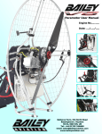
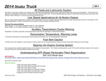
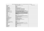
PAGE
2013 Isuzu Truck
2 .1
INSTALLATION OF BODY AND SPECIAL EQUIPMENT
Clearances
Engine
At least 1.6 inches of clearance should be maintained around the engine. No obstacles should be added in front of the radiator or intercooler.
Front and Back
Clearance
1 inch
Transmission
The transmission is removed from the rear. Enough clearance must be provided to allow rearward movement of the transmission assembly. Clearance should
be sufficient to allow 5 to 6 inches of unrestricted movement of the transmission assembly. In addition, provide at least 2 inches of clearance around the control
lever on the side of the transmission to allow free movement without any binding.
Front and Back
Clearance
1 inch
2013 Isuzu Truck
(Installation of Body and Special Equipment Section – continued on next page)
PAGE
2013 Isuzu Truck
2 .2
(Installation of Body and Special Equipment Section – continued from next page)
At least 6 inches of clearance should be maintained above the transmission to allow easy removal of the upper cover for manual transmissions.
At least 2 inches of clearance should be maintained above the automatic transmission to allow for transmission removal.
Front and Center Propeller Shafts
At least 1.25 inches of clearance should be maintained around front and center propeller shafts.
2013 Isuzu Truck
(Installation of Body and Special Equipment Section – continued on next page)
PAGE
2013 Isuzu Truck
2 .3
(Installation of Body and Special Equipment Section – continued from previous page)
Rear Propeller Shaft
With the rear springs at maximum deflection, at least 1.25 inches of clearance should be provided over the rear propeller shaft.
2013 Isuzu Truck
(Exhaust System Section – continued on next page)
PAGE
2013 Isuzu Truck
2 .4
(Installation of Body and Special Equipment Section – continued from previous page)
Exhaust System
The exhaust system has a crucial role in meeting 2010 EPA regulations. In order to maintain compliance with the 2010 EPA emissions levels the Diesel Particulate
Filter (DPF) and SCR package must not be moved. The distance between the engine exhaust manifold down pipe and Diesel Particulate Filter (DPF) / Selective
Catalyitic Reduction Package (SCR) must be maintained and the pressure in the system must be sustained at a constant level. Due to increased temperatures
in the exhaust system during the regeneration cycle and the heat stress caused by these temperatures, body builders should closely evaluate the placement of
equipment and provide protection to these added components as needed.
Diesel Particulate Filter and Selective Catalytic Reduction (SCR) Restrictions
The DPF/SCR has exhaust pressure pipes and temperature sensors. Care must be taken when a body is installed so as to not damage pipe sensors.
The DPF/SCR should be free from impact or vibration during body installation. The DPF/SCR must have enough room for disassembly of the unit for service
and cleaning.
The DPF/SCR switch in the cab should not be removed or disabled. No modification or relocation of the DPF/SCR unit, pressure pipes, and sensor is permitted.
No Modification Zones
The DPF/SCR unit CAN NOT be modified or moved .
The DEF tank and pump CAN NOT be modified or removed. DEF lines and coolant lines CAN NOT be modified or rerouted.
2013 Isuzu Truck
(Installation of Body and Special Equipment Section – continued on next page)
PAGE
2013 Isuzu Truck
2 .5
(Installation of Body and Special Equipment Section – continued from previous page)
EXHAUST CLEARANCES
If flammable materials such as wood are used in the body, provide at least 3.9 inches of clearance between the body and any parts of the exhaust pipe,
DPF/SCR Package. If it is impossible to maintain the minimum clearance, use a heat shield. Also use a heat shield if an oil pump or line is located above the
exhaust pipe, muffler or catalytic converter.
1) Clearances around SCR system components must be greater than 25mm at all times to avoid potential contact between the body and the exhaust compo-
nents. The 25mm allows for thermal expansion and assembly tolerance of the exhaust system. It does not account for dynamic movement in the body due to road conditions and other loads. Body companies are instructed to adjust this 25mm clearance as required to account for body displacement while driving.
This guidance does not supercede guidance or exhaust clearances for temperature sensitive or flameable components.
2) Exhaust temperatures have not changed since the introduction of DPF in 2007.
2013 Isuzu Truck
(Installation of Body and Special Equipment Section – continued on next page)
PAGE
2013 Isuzu Truck
2 .6
(Installation of Body and Special Equipment Section – continued from previous page)
Exhaust system surface temperatures During Manual Regeneration
N-Series Modification Guideline (heat issue)
(EXHAUST PIPE HEAT)
2013 Isuzu Truck
(Installation of Body and Special Equipment Section – continued on next page)
PAGE
2013 Isuzu Truck
2 .7
(Installation of Body and Special Equipment Section – continued from previous page)
Rear Wheel Axle
The design and installation of the body should allow sufficient clearance for full vertical movement of the rear wheels and axle when the vehicle travels over rough
or unlevel surfaces.
See Note
Note: For recommended clearances, please refer to the Rear Axle Chart in each model’s respective section.
Other Clearances
The transmission control cable may be broken if it is bent by or interferes with the body and its fixtures. To prevent this, 1 inch of minimum clearance should be
provided. When cable is detached from body mounting, be sure not to bend the cable.
Accessibility to the grease nipple on the rear spring bracket/shackle should be provided so that serviceability with a grease gun is not hampered.
Parts Brake Hose
Parking Brake Cable Fuel Hose Shock Absorber
2013 Isuzu Truck
Minimum Clearance 6.7 in. 1.6 in. 1.2 in. 1.6 in. 2.4 in. 1.2 in. Location
Axle Side
Frame Side
—
—
Axle Side
Frame Side
(Installation of Body and Special Equipment Section – continued on next page)
PAGE
2013 Isuzu Truck
2 .8
(Installation of Body and Special Equipment Section – continued from previous page)
Body Installation
Chassis
To maintain the performance of the truck chassis, either a side member or subframe should always be used for body mounting. Body mounting with low rigidity will
often adversely affect riding comfort.
NPR ECO-MAX Complete Vehicle Frontal Area Calculation
Completed Vehicle
Frontal Area (ft2) equal
to or less than IVD max
=
Body Outside Height
(H, in inches) x Body Outside Width
(W, in inches) / 144
+
Cab/Chassis Non-Overlap Area
(from Table, in ft2 )
TABLE 1
Cab/Chassis Non-Overlap Area, ft2
M, Body Mounting Height (Between the bottom of Body and the Top of Frame Rail, in inches)
W
Body With
Completed Vehicle Frontal Area Calculation:
The method used to certify EPA’10 emissions compliance of the NPR ECO-MAX has
completed vehicle frontal area and curb weight restrictions. The Completed Vehicle
Manufacturer is responsible for ensuring that the completed vehicle meets these limits
so as to ensure emissions compilance. For reference, the frontal area limit is 74.5 ft2
and the curb weight limit is 9,660 lbs.
Caution: Always consult the Incomplete Vehicle Document for the most up to date
information regarding completed vehicle requirements. A copy of the IVD is also available in the Isuzu Body Buidlers Guide
2
2.5 3
3.5 4
4.25 4.5 5
5.5 6
6.5 7
7.5 8
84’’
16.5 16.8 17.1 17.4 17.6 17.8 18.0 18.2 18.5 18.8 19.1 19.3 19.6 19.9
90’’
16.4 16.8 17.0 17.3 17.6 17.8 17.9 18.1 18.4 18.7 19.0 19.2 19.6 19.8
96’’
16.2 16.5 16.7 17.1 17.3 17.4 17.6 17.8 18.2 18.4 18.7 19.0 19.3 19.5
EXAMPLE: 90” Outside Width, 85.6” Outside Height (79” Inside Height) body, mounted on 4” Long Sills
with 2.5” of mounting wood. Body mounting height is 6.5” (4” Long Sill + 2.5” Wood)
Body frontal area is 90 x 85.6 / 144 = 53.5 ft2
Non-Overlap Area (from Table 1) = 19.0 ft2
Total completed vehicle frontal area is 53.5 ft2 + 19.0 ft2 = 72.5 ft2 (below limit)
Calculating the frontal area of the completed vehicle is easy. There are two components of the completed vehicle frontal area: the area of the body, and the area of the
cab/chassis that does not overlap with the body. The body frontal area is the outside
height of the body multiplied by the outside width of the body. The Cab/Chassis NonOverlap Area (in square feet) is dependant on the size of the body and how high it is
mounted above the top of the frame rail. Use the Table 1 below to determine the NonOverlap Area.
2013 Isuzu Truck
(Installation of Body and Special Equipment Section – continued on next page)
PAGE
2013 Isuzu Truck
2 .9
(Installation of Body and Special Equipment Section – continued from previous page)
Mirrors
The Isuzu NPR series chassis will accommodate up to 96 inch wide bodies without modification to the mirror brackets.
The Isuzu NPR-HD, NQR ,and NRR chassis will accommodate up to 96 inch wide bodies without modification to the mirror brackets. Bodies from 97 to 102
inches wide will require that the mirror brackets be modified. This Modification can be made at the port and the vehicle order/label will indicate a Regular Product
Option of IU3 indicating “Mirror Bracket for 102 wide body”. The brackets can also be modified by the N-Series Dealer or the Body Company by installing mirror
brackets ordered from Isuzu Parts.
Side Step Door Installation recommendations
Floor of body should be at least 10” above frame rail (2.5” wood + 4” long sill + 3” cross sill + 1.125” floor)
Forward end plate of step well area can interfere with SCR system
All body components should maintain a minimum 1.0” of clearance to exhaust components UNDER ALL (DYNAMIC) CONDITIONS.
(Body company will need to add to this 1.0” clearance to account for flex or movement in the body)
Outer heat shield on SCR system can be removed prior to mounting body if required for clearance
Care should be taken to adequately shield exhaust
Driver’s side steps can also be accommodated, if door is located behind DEF tank
Battery may have to be relocated, depending on door location
Access hatch for DEF tank fill may have to be added, depending on door location
DPF/SCR Heat shield Removal
The exhaust external heat shield does not impact vehicle emissions or emissions system durability. This shield can be removed or modified in order to facilitate
body or equipment mounting, but the completed vehicle manufacturer should ensure that, when completed, the exhaust will be adequately shielded to prevent
unintentional contact with hot exhaust components, and that heat transfer to body components is not so high as to present safety or durability risks. Detailed
information on removal of the heat shield can be found in the Isuzu service manual available on line at www. isuzutruckservice,com.
2013 Isuzu Truck
(Installation of Body and Special Equipment Section – continued on next page)
PAGE
2013 Isuzu Truck
2 .10
(Installation of Body and Special Equipment Section – continued from previous page)
Heat Shield
DPF/SCR Heat Shield Removal
this bracket
can be Cut Off
19.6”
2013 Isuzu Truck
(Installation of Body and Special Equipment Section – continued on next page)
PAGE
2013 Isuzu Truck
2 .11
(Installation of Body and Special Equipment Section – continued from previous page)
Special Equipment on the Chassis
When installing special equipment on the chassis, extra consideration must be given to the weight and construction of the equipment to assure proper distribution of the load. Localization of the load should be prevented. All special equipment should be properly secured into position. We recommend the use of sub
frame members when installing special equipment.
Sub frame Design and Mounting
The sub frame assembly should be mounted as close to the cab as possible. It should be contoured to match the shape and dimensions of the chassis frame as
closely as possible
NPR ECO MAX
NPR-HD, NQR, NRR
2013 Isuzu Truck
(Installation of Body and Special Equipment Section – continued on next page)
PAGE
2013 Isuzu Truck
2 .12
(Installation of Body and Special Equipment Section – continued from previous page)
Subframe Contour
Contouring of the front end of the subframe members as shown in the three illustrations below will prevent stresses from being concentrated on certain areas of
the chassis frame.
2013 Isuzu Truck
(Installation of Body and Special Equipment Section – continued on next page)
PAGE
2013 Isuzu Truck
2 .13
(Installation of Body and Special Equipment Section – continued from previous page)
When using a steel subframe, do not close the end of the subframe.
Prohibited Attachment Areas
Do not attach the sub frame with a bolt or bracket to the chassis frame at the points indicated in the following illustrations.
1. At the front end of the subframe. The attaching bolt or bracket must be at least 2 inches behind the kick up point of the subframe.
2013 Isuzu Truck
(Installation of Body and Special Equipment Section – continued on next page)
PAGE
2013 Isuzu Truck
2 .14
(Installation of Body and Special Equipment Section – continued from previous page)
2. Front U-bolt and Mounting Bracket, Mounting Locations Ahead of Transmission
Mandatory location due to after treatment device location and interior frame components. The chassis will be supplied with one steel crush block in cab for left hand forward body attaching location as
illustrated in the drawings below and one one body mounting bracket (YELLOW) attached to the right hand frame rail in the location shown in the drawings below. Body Builder will be required to design
a mating bracket for attaching the body to the yellow chassis body mounting bracket (Ref page 2.16 for illustration of bolt clamping 2 brackets ). No U bolt type attaching allowed.
NPR ECO MAX
Forward
NPR-HD, NQR, NRR
Forward
Body Mounting
Bracket Location
Body Mounting
Bracket Location
1.38 in. (35 mm)
Crush Block
Location
Crush Block
Location
Crush Block and U-Bolt
(Left Hand -Rail)
2013 Isuzu Truck
Body Mounting Bracket
(Right Hand -Rail)
(Installation of Body and Special Equipment Section – continued on next page)
PAGE
2013 Isuzu Truck
2 .15
(Installation of Body and Special Equipment Section – continued from previous page)
U-Bolt Placement – 150” W/B Crew Cab
Front, RHS U-bolt on 150” Wheelbase Crew Cab interferes with after treatment system. Isuzu will supply body
mounting bracket on chassis to facilitate body mounting on the passenger side of the vehicle as Illustrated.
Crew Cab 150’’ WB
DIMNENISIONS
A
Crew Cab 150’’ WB - Body Mounting Bracket (A) Location
(A)
1.38 in. (35 mm)
Body Mounting Bracket will be painted
“YELLOW” for easy identification
2013 Isuzu Truck
(Installation of Body and Special Equipment Section – continued on next page)
PAGE
2013 Isuzu Truck
2 .16
(Installation of Body and Special Equipment Section – continued from previous page)
Subframe Mounting
Within 8 inches of bends in the chassis frame or the attachment points of any crossmembers.
Bracket Installation
Mounting brackets should be clamped to the chassis frame using bolts. For proper positions in which to install the bolts, refer to the
preceding section and the section “Modifications to the Chassis Frame.” In addition to the illustrated bracket and U -bolts a shear plate
may be required for adequatley body mounting. The body company will be responsible for engineering their own mounting system.
The frame material is a heat treated, carbon manganese,
low alloy steel with good weldability. The frame has a 80/40 mm
modular hole spacing standard. This standard pattern will assist
in body mounting.
2013 Isuzu Truck
(Installation of Body and Special Equipment Section – continued on next page)
PAGE
2013 Isuzu Truck
2 .17
(Installation of Body and Special Equipment Section – continued from previous page)
MODULAR FRAME HOLE PATTERN
The fame material is a heat treated carbon manganese, and low alloy steel with good welding characteristics. The frame has an
80/40mm modular hole spacing standard. This standard pattern will assist with body mounting.
Depending on model, wheelbase and
chassis specification some holes are in use
and some holes are intentionally missing.
(Subject to change without notice).
Note: Re-tighten all attaching parts that are loosened during body installation.
2013 Isuzu Truck
(Installation of Body and Special Equipment Section – continued on next page)
PAGE
2013 Isuzu Truck
2 .18
(Installation of Body and Special Equipment Section – continued from previous page)
U-bolt Installation
When U-bolts are used to retain the subframe, reinforcement blocks must be installed in the frame members. This will prevent distortion of
the frame flange as they are tightened. The drawing indicates the correct placement of reinforcement blocks. If you use wood blocks, be sure
that there is sufficient clearance between them and any parts of the exhaust system. The use of J-bolts to retain the subframe is strictly
prohibited.
If any fluid lines or electric cables are located near the reinforcement blocks, you must provide at least 0.4 inches of clearance between rigid
or stationary portions, and at least 1.6 inches between moveable or flexible portions of the lines.
CAUTION:
U-Bolt placement is critical with new emission systems
and controls. Extra care must be taken when
placing bodies on chassis so as not to damage these
components.
For the installation positions of the U-bolts, refer to “Prohibited Attachment Areas.”
Crew Cab Body / Frame Requirements
The Crew Cab NPRHD and NQR will be available in two wheelbases, 150 and 176 inches. CA will be 88.5 and 114.5 inches.
On this model chassis, Isuzu Commercial Trucks of America, Inc. (ICTA) will require that the body installed on the chassis have an understructure manufactured
with any of the following structural steel “C” channels:
4” x 1-5/8”, 7.5 lb./ft.
5” x 1-3/4”, 6, 7 or 9.0 lb./ft.
6” x 2”, 8.2, 10.5 or 13 lb./ft.
2013 Isuzu Truck
(Installation of Body and Special Equipment Section – continued on next page)
PAGE
2013 Isuzu Truck
2 .19
(Installation of Body and Special Equipment Section – continued from previous page)
Modification of the Frame
Modifications of the chassis frame should be held to an absolute minimum. Modification work should be performed according to the instructions in the following
paragraphs.
When modification is complete, chassis frame members should be carefully inspected to eliminate the possibility of any safety-related defects.
NOTE: PLEASE REFER TO NOTES ON CHASSIS FRAME MODIFICATION WITH ANTILOCK BRAKES.
Working on Chassis frame
The chassis frame is designed and built with consideration for proper load distribution. Sufficient physical strength is provided when the load is evenly
distributed. Installation of special equipment on the chassis frame can cause variations in load distribution. If even distribution of load is not kept in mind when
the equipment is installed, localization of stresses on specific areas of the frame could cause cracking of the chassis frame members or other problems, even if
the total weight of the equipment is within the design limit.
The chassis frame is designed as an integral unit. Therefore, we do not recommend cutting the chassis frame under any circumstances.
Drilling and Welding
IMPORTANT NOTE: For vehicles equipped with electronic engines and or electronic or hydra-matic transmissions, electric arc welding must be done with the negative battery cable disconnected.
1. Do not drill or weld in the shaded portions of the chassis frame members. Do not weld within 0.8 inches from the edges of any existing holes.
2. Hold the length of any welding beads within 1.2-2.0 inches. Allow at least 1.6 inches between adjacent welding beads.
3. All holes must be drilled. Do not use a torch to make any holes.
4. All riveting must be done with cold rivets. Do not use hot rivets.
5. The flange of the chassis frame must not be cut under any circumstances.
6. The subframe must be attached to the chassis frame with bolts. Do not weld.
7. Repaint exposed metal after drilling.
2013 Isuzu Truck
(Installation of Body and Special Equipment Section – continued on next page)
PAGE
2013 Isuzu Truck
2 .20
(Installation of Body and Special Equipment Section – continued from previous page)
A - no more than 0.59 inches in diameter
B - must be more than H/5 for welding
and H/7 for holes
C - must be more than 1.57 inches
H
H = Frame Height
Reinforcement of Chassis Frame
Reinforcements must be installed to prevent the considerable variation in the section modulus. They must be welded so as to avoid localized stresses.
The frame of the N-Series is made of SAPH440 mild steel.
The drawing on the following page illustrates correct and incorrect methods of frame reinforcement.
Welding
1. Keep reinforcement plates and chassis frame free from moisture and water.
2. Avoid cooling with water after welding.
3. Use a suitable means to protect pipes, wires, rubber parts, leaf springs, etc. against heat and effect of sputtering.
4. Remove fuel tank assembly when welding portions near the fuel tank.
5. Remove coat of paint completely when welding painted areas. Repaint exposed metal after welding.
2013 Isuzu Truck
(Installation of Body and Special Equipment Section – continued on next page)
PAGE
2013 Isuzu Truck
2 .21
(Installation of Body and Special Equipment Section – continued from previous page)
Fluid Lines
Do not disturb the layout of any brake lines or fuel lines unless absolutely necessary. When modification is needed, follow the instructions below carefully to
ensure safety. Brake fluid lines must not be cut and spliced under any circumstances. We do not recommend the cutting or splicing of any fuel lines, but if it is
absolutely necessary, be sure that the correct fitting and tools are used to form the joint, and then pressure test the joint. Steel lines are metric sizes.
Preparation of Additional Lines
1. Where possible, use only genuine Isuzu lines as supplied by authorized Isuzu dealers.
2. Use the correct metric flaring and bending tools to form the lines.
3. Avoid repeated bending. Do not use heat for flaring and bending the lines. Before and after forming the new lines, examine them carefully for scratches,
distortion, dents and the presence of any foreign matter.
2013 Isuzu Truck
(Installation of Body and Special Equipment Section – continued on next page)
PAGE
2013 Isuzu Truck
2 .22
(Installation of Body and Special Equipment Section – continued from previous page)
Installation of Additional Lines
Install new lines away from adjacent parts and away from any sources of heat.
1. A minimum clearance of 0.4 inches must be maintained between lines. Where necessary, clip the lines into position in order to maintain this minimum
clearance.
2. Minimize any crossing between lines. If a crossing is unavoidable, use the following procedure:
a. At least 0.4 inches of clearance should be maintained between lines at the crossing point.
b. If the 0.4 inches of clearance cannot be maintained, or if the lines are subject to vibration, clip them securely.
3. Plan the bends and clipping points of the lines to minimize vibration and the resulting fatigue.
4. Use rust-proofed clips and apply vinyl coating to the portions of the lines to be clipped.
5. Install new lines in positions where they are protected against water, dirt, grit, sand, rocks and other foreign matter that can come from above or below, or can be flung up by the wheels.
Electrical Wiring and Harnessing
To increase the reliability of the wiring, all frame harnesses are covered with corrugated vinyl tubing. The following instructions apply to extending or modifying
these harnesses. See the Electrical Section for information on commonly used circuits in the NPR, NPR HD, NQR, NRR.
2013 Isuzu Truck
(Installation of Body and Special Equipment Section – continued on next page)
PAGE
2013 Isuzu Truck
2 .23
(Installation of Body and Special Equipment Section – continued from previous page)
Wiring
1. Most wiring connections on Isuzu vehicles are made with terminals. We recommend the use of terminals when splicing cables and wires.
2. When splicing, use new wire of the same gauge, and do not make splices inside the corrugated tubing.
3. When making connections to the end of the harness, make sure the connections are electrically perfect. Use insulating tape as needed to prevent the entry of water, which results in short circuits and/or corrosion.
4. When making new circuits, or modifying circuits already installed, make the cables only just taut enough to remove any slack. Use clips or grommets where required to protect cables from heat or sharp edges. When cables must run near the exhaust system, see the instructions in the “Exhaust System” section.
5. Always use rustproof clips, and apply vinyl coating to that portion of the clips in direct contact with the harnesses. No scotch clips or connectors.
6. To minimize the vibration of the harness, clipping points should be set up according to the table.
Harness Diameter less than 0.2 in. 0.2 in. ~ 0.4 in. 0.4 in. ~ 0.8 in. Clip Distance
less than 11.8 in.
approx. 15.7 in.
approx. 19.7 in.
7. When changing the length of the battery cable, do not cut or splice the existing cable. Make up a new cable of the correct length and wire gauge for the load and distance, without splices.
8. When using connectors, use a socket (female) connector on the electrical source side and a plug (male) connector on the electrical load side to lower the possibility of a short circuit when disconnected.
9. When connecting cables to moving or vibrating parts such as the engine or transmission, be sure to maintain sufficient slack in the wiring to absorb the vibration. Follow the example of existing cables connected by Isuzu. Keep flexible cables clear of other parts.
10. Do not use vinyl tape in the engine compartment. The heat will tend to make it peel off. Use plated steel clips coated with rubber or vinyl.
11. When locating auxillary equipment or lines near the ECM caution should be used in order to protect the ECM from excessive vibration, heat or
chemical reactions.
2013 Isuzu Truck
(Installation of Body and Special Equipment Section – continued on next page)
PAGE
2013 Isuzu Truck
2 .24
(Installation of Body and Special Equipment Section – continued from previous page)
2013 Isuzu Truck
(Installation of Body and Special Equipment Section – continued on next page)
PAGE
2013 Isuzu Truck
2 .25
(Installation of Body and Special Equipment Section – continued from previous page)
Wire Color Code
The electrical circuits of the N-Series Chassis Cab are connected with low-voltage stranded wire for automotive applications.
The color coding standards are as follows for the N-Series Chassis Cab:
(1) Black (2) White (3) Red (4) Green B
W
R
G
Starter circuits and grounds Generator (alternator) circuit Lighting circuit Signal circuit (5) Yellow (6) Brown (7) Light Green (8) Blue Y Instrument circuit
Br Accessory circuit
Lg Other circuit
L Windshield wiper motor circuit
Maximum Allowable Current
Harness Design Diameter (mm) AWG Equivalent No. of Wires/Wire Diameter (mm) Cross Sectional Area (mm2) Maximum Allowable Current (Amps)
100 00 217/0.80 109.1 363
85 0
169/0.80 84.96 305
60 1
127/0.80 63.84 248
50 1
108/0.80 54.29 223
40 1
85/0.80 42.73 191
30 2
70/0.80 35.19 171
20 4
41/0.80 20.61 123
15 6
84/0.45 13.36 93
8
8
50/0.45 7.952 68
5
8
65/0.32 5.228 51
3
12 41/0.32 3.297 39
2
14 26/0.32 2.091 29
1.25 16 16/0.32 1.287 21
0.85 18 11/0.32 0.8846 17
0.5 20 7/0.32 0.5629 13
Reference: The values given in the “maximum allowable current” column are based on the ambient temperature condition of 104oF
with temperature increase of 1040F.
2013 Isuzu Truck
(Installation of Body and Special Equipment Section – continued on next page)
PAGE
2013 Isuzu Truck
2 .26
(Installation of Body and Special Equipment Section – continued from previous page)
Electrical System Modifications
Modifications/add-on wiring must be carefully reviewed to ensure compatibility with the base vehicle wiring by reviewing system schematics, wire routing paths,
harness connections, etc. Due to the wide range of modifications that may be required for vocational needs, it is not feasible for the O.E.M. to take into account
all potential revisions. For this reason, any person modifying existing vehicle wiring must assume responsibility that the revisions have not degraded the electrical
system performance. Any add-on wiring needs to be properly fused and routed to prevent cut, pinch, and chafe problems, as well as avoid exposure to
excessive heat. Care must be exercised that existing vehicle interfaces do not have their current load capabilities exceeded, and that the respective control
devices are not overloaded. Added wire size should be at least as large as the wire to which it is attaching in order for fuse protection to be maintained
A Packard electric wiring repair kit is available through Kent-Moore (P/N J38125-B) (Phone # 1-800-345-2233). This kit contains instructions, tools and
components for making repairs to wiring harness components. This kit would also greatly assist in accomplishing necessary add-on wiring such as body marker
lamps, so that system reliability/durability is maintained.
Electrical wiring components can be obtained through your authorized Isuzu dealers. Packard Electric components are also available through Power and Signal
(www.powerandsignal.com). Power and Signal may also be able to assist in making necessary wiring additions by providing custom wiring stubs or
jumpers to your specifications.
Caution: Before servicing any electrical component, the ignition key must be in the LOCK position and all electrical loads must be OFF, unless instructed
otherwise in Isuzu service procedures. If a tool or equipment could easily come in contact with a live exposed electrical terminal, also disconnect the negative
battery cable. Failure to follow these precautions may cause personal injury and/or damage to the vehicle or its components.
Exhaust System
Modification of the exhaust system should be avoided. If modifications are absolutely necessary, the following points should be maintained.
1. Maintain the clearance specified in the “Exhaust System” table between all parts of the exhaust system and any fuel lines, brake
lines, brake hoses, electrical cables, etc. The exhaust outlet should not point toward any of these parts.
Brake lines Flexible brake hoses Wiring harnesses and cables Steel fuel lines Rubber or vinyl fuel hoses 2013 Isuzu Truck
Clearance
2.4 in. or more. (If the combined section of a group of parallel brake lines is more than 7.8 in., a clearance of 7 in. or more should be provided.)
7.8 in. or more. (The temperature of flexible brake hoses should not exceed 158oF. If the highest temperature is not measur
able, a clearance of more than 15.7 in. should be maintained between the hoses and the exhaust system.)
7.8 in. or more. (The temperature of flexible brake hoses should not exceed 158oF. If the highest temperature is not
measureable, a clearance of more than 15.7 in. should be maintained between the hoses and the exhaust system.)
3.1 in. or more.
5.9 in. or more.
(Installation of Body and Special Equipment Section – continued on next page)
PAGE
2013 Isuzu Truck
2 .27
(Installation of Body and Special Equipment Section – continued from previous page)
2. If a tool box is installed, it should preferably be made from steel. If a wooden tool box is installed, at least 7.8 inches of clearance should be maintained between the tool box and any parts of the exhaust system.
3. If the exhaust system is modified, it is the responsibility of those making the modification to ensure that the noise level meets appropriate standards.
4. If the exhaust system is modified it is the responsibility of those making the modification to ensure that the emission levels meet appropriate standards.
Fuel System
Relocation of the fuel tank, or installation of additional fuel tanks, is not recommended. If modifications to the fuel system are unavoidable, follow these
recommendations:
1. Maintain adequate clearance between the fuel tank and any other device or structure.
2. Do not connect any additional fuel hose.
Rear Lighting
Brackets installed are temporary. Please do not use these brackets for body installation.
Serviceability
No matter what other modifications or changes are made, access to components requiring daily preventive maintenance or other routine service must not be
obstructed. This includes:
1. Inspection, filling and draining of engine oil and cooling water.
2. Inspection, filling and draining of transmission fluid.
3. Adjustment, removal and installation of the fan belts.
4. Inspection, filling and removal of the battery and battery cover.
5. Inspection and filling of brake fluid.
6. Inspection and bleeding of the brake system and servo unit.
7. Maintenance of clearance for tightening of check bolt on brake safety cylinder.
8. Operation of the spare tire carrier, including mounting and dismounting of the spare tire.
9. Adjustment, removal and installation of distributor and/or cover.
2013 Isuzu Truck
(Installation of Body and Special Equipment Section – continued on next page)
PAGE
2013 Isuzu Truck
2 .28
(Installation of Body and Special Equipment Section – continued from previous page)
Wheelbase Alteration
With certain applications, it may become necessary to alter the wheelbase of the chassis. The next two sections provide the suggested
guidelines for accomplishing either shortening or lengthening of the wheelbase.
Shortening/Lengthening the Wheelbase Without Altering the Frame
Since the frame is an integral part of the chassis, it is recommended that the frame not be cut if it is possible to avoid it. When shortening/lengthening the
wheelbase on some models, it is possible to do so without cutting the frame. This is possible on models which have a straight frame rail. If the chassis does not have a straight frame rail, it may still be necessary to cut the frame. For instructions on shortening/lengthening these chassis, refer to the
“Altering the Wheelbase by Altering the Frame” section of this book. Otherwise, the wheelbase may be shortened/lengthened by removing the rear suspension,
drilling new suspension mounting holes at the appropriate spot in the frame, and sliding the rear suspension, suspension liner, and suspension crossmembers
forward or aft.
The suspension and suspension crossmembers’ rivet holes left in the frame rail flange must be filled with GRADE 8 bolts and hardened steel washers at both the
bolt head and nut, HUC bolts or GRADE 8 flanged bolts and hardened steel washers at the nut. When shortening/lengthening the wheelbase in this manner, the
following guidelines must be adhered to:
1. All frame drilling must comply with the DRILLING AND WELDING section of this book.
2. All rivet holes left in the frame rail flange from the suspension and suspension crossmembers must be either filled with GRADE 8 bolts and hardened steel washers at both the bolt head and nut, HUC bolts or GRADE 8 flanged bolts and hardened steel washers at the nut.
3. The components required to be slid forward or aft are the suspension and suspension hangers, suspension crossmembers and suspension frame liner.
Altering the Wheelbase by Altering the Frame
Even on a straight frame rail, it may be desirable to cut the frame and lengthen or shorten the wheelbase rather than simply sliding the rear
suspension back or forward. The following section offers some guidelines and suggestions for cutting and lengthening or shortening the frame.
Glossary of Terms – Chassis Wheelbase Alteration
CA – Length from back-of-cab to rear axle centerline in inches.
AL – Added length (in case of a lengthened wheelbase). Difference between WB (new) and WB (old).
SL – Shortened length (in case of shortened wheelbase). Difference between WB (old) and WB (new).
2013 Isuzu Truck
(Installation of Body and Special Equipment Section – continued on next page)
PAGE
2013 Isuzu Truck
2 .29
(Installation of Body and Special Equipment Section – continued from previous page)
1. Determine the added length (AL) or shortened length (SL) required to lengthen or shorten chassis. (For added wheelbase: New CA = CA + AL; For shortened wheelbase: New CA = CA – SL.)
2. Obtain the material to be used as the insert for the lengthened wheelbase in the correct length (AL). The insert must have the same cross sectional
dimensions and yield strength as the original frame rail.
3. Divide the new CA by two (2). Measure (new CA)/2 from the center of the rear axle forward and mark this point on the chassis frame (see figure below).
4. Cut the chassis frame at this point. If the wheelbase is to be lengthened, addition of the previously obtained insert (of length AL determined in step 1) will be made at this time. If the wheelbase is to be shortened, measure the distance (SL) forward of this cut and remove a length (SL) section from the chassis frame (see figure below). Insure that an adequate area on the frame remains for the required addition of the necessary reinforcements. These are the only suggested places for cutting the frame and reinforcements but may be changed upon the advice of Isuzu Commercial Trucks of America, Inc. Application Engineering.
2013 Isuzu Truck
(Installation of Body and Special Equipment Section – continued on next page)
PAGE
2013 Isuzu Truck
2 .30
(Installation of Body and Special Equipment Section – continued from previous page)
5. When welding the insert (length AL for wheelbase lengthening) to the original frame rail, a continuous butt weld must be used at the splices. When shortening the wheelbase, weld the ends of the chassis frame together with a continuous butt weld over the junction of the frame ends. Weld both the inside and outside of the frame rails using welding techniques prescribed by established welding standards (ref. SAE J1147) and in accordance with this guide.
An example of this weld is shown below.
6. Determine the appropriate additional internal reinforcements which are required using this equation:
Reinforcement Length = AL + 6 x (original frame rail web depth).
The figure below shows how this reinforcement is to be placed over the extended or shortened section of the frame rail.
D = Original frame rail web depth
The suggested cross section of this reinforcement is a snug fit inner channel. If the new wheelbase exceeds the upper limit of the optional wheelbases of this
model, i.e.; a “long bridge”, it may be necessary to use an “inverted L” reinforcement in addition to the snug fit channel reinforcement (see figures on next page).
Application Engineering should be consulted for approval of such cases. It should be noted that these methods of reinforcements, and any other methods which
may be used, require a 45o angled cut at both ends to avoid stress concentrations in the frame (note the figures under item 7).
2013 Isuzu Truck
(Installation of Body and Special Equipment Section – continued on next page)
PAGE
2013 Isuzu Truck
2 .31
(Installation of Body and Special Equipment Section – continued from previous page)
7. The reinforcements must be fastened securely to only the web of the original chassis frame rail. The reinforcement must be held rigidly in place using either HUC bolts, GRADE 8 bolts and hardened steel washers at both the bolt head and nut, or GRADE 8 flanged bolts and hardened steel washers at the nut. Below are some suggested bolt patterns. It should be noted that these bolt patterns must not align the bolts vertically, i.e.: the bolt pattern must be
staggered.
8. Lengthening the frame will also require extending the brake lines, basic chassis electrical harness. It is recommended that the original brake lines be removed and replaced with brake lines of the same diameter as the original lines and of the appropriate length. The extended ABS brake lines must be supported
back to the frame to prevent vibration. The electrical harness must be extended in accordance with the ELECTRICAL WIRING AND HARNESSING section of this book. ICTA offers an electrical extension harnesses for the N-Series chassis when a wheelbase is lengthened. One wheelbase longer is the
recommended maximum wheelbase extension (please refer to the drive line section and particular models for number of drivelines and their maximum lengths). The extension of a wheelbase will require an extension harnesses (pn 8980626380)and 12 clips (5097003230).
Part numbers 2008/2009/2010/2011/2012 harness extension harness
2008 -2012 NPR NPR-HD NQR / NRR PN 8980626380 CHAS WRG HARNESS ASM; QTY 1
2008 -2012 NPR NPR-HD NQR / NRR PN 5097003230 CHAS RR WRG HARNCLIP; QTY 5
9. The propeller shafts’ overall length will also need to be lengthened or shortened. If the extension is within the limits of the optional wheelbases of the
respective model, the exact propeller shaft lengths and angles are given on or about Page 12 of the respective sections of this book. If the modified
wheelbase exceeds the optional wheelbases of the respective model, the following guidelines must be adhered to:
2013 Isuzu Truck
(Installation of Body and Special Equipment Section – continued on next page)
PAGE
2013 Isuzu Truck
2 .32
(Installation of Body and Special Equipment Section – continued from previous page)
a. Propeller Shaft Length
The maximum propeller shaft lengths (pin to pin) for the respective models are shown in the table below.
ENGINE
MODEL
Propeller Shaft Diameter (in.) Maximum Propeller Shaft Length (in.) GAS
NPR 3.54
52.9 NPR-HD 3.54
52.9 NPR
3.18
43 NPR-HD
3.54
52.9
NQR 3.54
52.9
NRR
3.54
52.9
b. Propeller Shaft Angles
The maximum propeller shaft angles, with respect to the previous shaft, are shown in the table below.
ENGINE
MODEL
Maximum Propeller Shaft Angle DIESEL
GAS
NPR 6.1o DIESEL
NPR-HD 6.1o NPR
6.1o NPR-HD
6.1o
NQR 6.1o
NRR
6.1o
c. The propeller shaft angles must be designed such that the angles will cancel to avoid propeller shaft whip.
d. The propeller shaft yokes must be assembled such that the propeller shaft yokes are “in phase.” “In phase” means that the yokes at either end of a given propeller shaft assembly are in the same plane.
10. Extending the frame will also require relocation and/or addition of crossmembers. If the extension is within the limits of the optional wheelbases of the
respective model, the exact crossmember locations and dimensions are given in the respective model sections of this book. If the modified wheelbase
exceeds the optional wheelbases of the respective model, the following guidelines must be adhered to:
a. The crossmember location will largely be determined by the propeller shaft lengths and where the center carrier bearing locations are for the propeller
shaft assembly.
b. A crossmember must be located at the front and rear spring hangers of the rear suspension (refer to the appropriate section of this book to see where these suspension crossmembers are to be located).
c. The crossmember must be constructed such that it supports both the upper and lower flange on each frame rail (see drawing on next page).
A crossmember such as the one on the next page may be constructed, or Isuzu crossmembers may be obtained from your Isuzu parts dealer.
2013 Isuzu Truck
(Installation of Body and Special Equipment Section – continued on next page)
PAGE
2013 Isuzu Truck
2 .33
(Installation of Body and Special Equipment Section – continued from previous page)
d. The maximum distance between crossmembers for the respective models is given in the table below.
ENGINE
GAS
MODEL
Maximum Distance Between Crossmembers (in.)
NPR 35.7o DIESEL
NPR-HD 35.7o NPR
35.7o NPR-HD
35.7o
NQR 35.7o
NRR
35.7o
e. The drilling for any additional holes in the frame rails must comply with the DRILLING AND WELDING section of this book.
11. All other aspects of lengthening or shortening the wheelbase must comply with the applicable section of this Body Builder’s Guide. For special applications and longer than recommended body lengths, ICTA Application Engineering must be consulted for approval. In the West Coast call 1-714-935-9327 and in the East Coast call 1-770-740-1620 x262.
12. Please contact applications engineering for guidelines on N SERIES CHASSIS frame modifications when the vehicle is equipped with an Antilock Brake System.
2013 Isuzu Truck
(Installation of Body and Special Equipment Section – continued on next page)