1
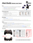
DISCONTINUED
PRODUCT
SITE MONITORING
■
■
■
■
■
■
■
■
AC3
Autochangeover Controller
USER MANUAL
DISCONTINUED
PRODUCT
TABLE OF CONTENTS
Section 1: INTRODUCTION.......................................................................................... 1
Specifications ................................................................................................................................................ 2
Section 2: INSTALLATION ........................................................................................... 3
Mounting........................................................................................................................................................ 3
Electrical Connections................................................................................................................................... 3
Connection to Liebert Environmental Units ................................................................................................... 5
Section 3: HARDWARE CONFIGURATION ................................................................. 7
DIP Switch Settings ....................................................................................................................................... 7
Common Alarm Output ................................................................................................................................. 7
Section 4: OPERATION................................................................................................ 9
LCD Display................................................................................................................................................... 9
Set Modes ................................................................................................................................................... 10
TABLE OF FIGURES
Figure 1.
Figure 2a.
Figure 2b.
Figure 3.
Figure 4.
Figure 5.
Typical System Configuration....................................................................................................ii
Flush-Mount Installation ........................................................................................................... 4
Display Panel Mounted Remotely from Electrical Box ............................................................. 6
Electrical Connections, Electric Box and Display ..................................................................... 8
LCD Display.............................................................................................................................. 9
Display Panel............................................................................................................................ 9
DISCONTINUED
PRODUCT
Common Alarm
Relay Output
24 VAC@ 5.0 AMP
(2 Unit Mode Only)
Power Source
24 VAC
AC3
N.O.
Control
Input
Common
Alarm
Output
UNIT 1
Control
Input
Common
Alarm
Output
UNIT 2
Control
Input
Common
Alarm
Output
UNIT 3
Figure 1. Typical System Configuration
DISCONTINUED
PRODUCT
DISCONTINUED
PRODUCT
Section 1: INTRODUCTION
The AC3 Autochangeover controller provides coordinated
control in systems with redundant environmental units. When
an alarm is detected in a Running unit, the AC3 enables a
Standby unit and responds to the unit in alarm as programmed
(see below). The AC3 controller also can balance the runtimes
of the units, by rotating the Running and Standby assignments.
The user can select from the control display panel:
• Running and Standby unit assignments
• Switchover (alarm) delay
• Overlap/Non-overlap delay
• Autosequence interval.
Additional selections can be made via DIP switches (accessible
by opening the display panel):
• 2 or 3 unit operation
• Shutdown units on alarm
• Overlap or Non-overlap operation
• Enable security code
The AC3 display panel includes a custom LCD screen and a sixbutton keypad. A piezoelectric buzzer provides audible
annunciation of alarms.
NOTE: New Feature. Inputs are
now contact-closures; 24VAC
powered inputs are no longer
necessary.
The electrical box contains an interface board with a power
supply (24 VAC input), 3 contact-closure inputs for the alarm
signal from each unit, and 3 relays to provide a dry contact
output to control each unit. Common Alarm relay output in the 2
unit mode is also available.
Contact Liebert Environmental Support at 1-800-543-2778
regarding installation, operation, or warranty issues.
Liebert AC3 • 1
DISCONTINUED
PRODUCT
Specifications
Electrical Specifications:
Voltage: 24 VAC, +/-10% of nominal
Power:
7.5 VA
Phase:
1
Frequency: 50/60 Hz
Environmental Conditions:
Operating Temperature:
5°C to 40°C
Operating Relative Humidity: 0% to 95% (non-condensing)
Operating Altitude:
up to 2000 meters
Dimensions:
Display Panel 3 1/2”H x 5”W x 1 1/8”D
89mm x 127mm x 29mm
3/4”
H
x
4
Electrical Box: 4
121mm x 121mm x 70mm
0.5 lbs
0.23 kg
3/4”W
x
0.91 kg
NOTE
This equipment has been tested and found to
comply with the limits for a Class A digital
device, pursuant to part 15 of the FCC rules.
These limits are designed to provide reasonable
protection against harmful interference when the
equipment is operated in a commercial
environment. This equipment generates, uses,
and can radiate radio frequency energy and, if
not installed and used in accordance with the
instruction manual, may cause harmful
interference
to
radio
communications.
Operation of this equipment in a residential area
is likely to cause harmful interference in which
case the user will be required to correct the
interference at his own expense.
NOTE
When the following symbols are displayed, they
indicate:
a.
Earth grounding conductor
b.
Alternating Current
2 • User Manual
DISCONTINUED
PRODUCT
2
3/4”D
Section 2: INSTALLATION
Mounting
The AC3 is completely tested, then shipped from the factory
disassembled for your convenience during installation. To begin
flush-mount installation, refer to Figure 2a. An optional 30-foot
control cable can be supplied to allow the display to be located
remotely from the electrical box. Refer to Figure 2b.
The electric box containing the power supply is designed for
flush-mounting into a finished interior wall. A wall plate is
supplied to cover the drywall opening, with the display mounted
directly in front of the wall plate/electric box.
1. Mount the electric box (Item 5) in the wall at a convenient
location.
NOTE: Use minimum
18 gauge wire for all
customer interface wiring.
2. Make each power and unit connection (to Item 4) by
inserting bare wire end into compression terminal and
tightening screw. Refer to Electrical Connections section.
If 30-foot cable is used, disconnect factory wire harness and
attach cable to screw terminals per Figure 3.
3. Route control cable through wall plate and electric box
cover, then connect to electrical box at TB1 (on Item 4).
4. Attach electric box cover (Item 3) with two (2) screws.
5. Remove the front cover from the AC3 display panel (Item 1)
by gently prying open at the slots on the top and bottom of
the display. Do not remove factory wiring from the control
assembly. Attach the control panel rear plastic and the wall
plate (Item 2) to the electric box with two (2) screws.
6. Snap display panel front onto the rear plastic part.
7. Apply power to the AC3. Operate the system to test alarm
monitoring, Running and Standby unit operation control,
and customer selected options.
Call Liebert Environmental Support at 1-800-543-2778 if
assistance is required for the installation or operation of your
AC3 autochangeover controller.
Electrical Connections
The AC3 autochangeover controller requires four-wire
connections to each Environmental unit under its control: two
wires for alarm input; the second pair for remote shutdown
control.
Liebert AC3 • 3
DISCONTINUED
PRODUCT
Figure 2a. Flush-Mount Installation
4 • User Manual
DISCONTINUED
PRODUCT
Caution: Ensure Environmental
unit has sufficient 24VAC power
to support the AC3, Liqui-tects or
any other auxiliary device.
Connection to Liebert
Environmental Units
NOTE: Exercise caution if
installing new AC3 as
replacement unit: remove power
from signal inputs, or damage to
unit may occur!
Liebert Env
Controller
SM - Standard
AM/AG - Advanced
L10 - Level 10
Microprocessors
L00 - Level 00
Microprocessor
mini-MATE 2
SSC** - Small System
Controller
It is recommended that the AC3 be powered independently from
an external 24VAC transformer. Optionally, the AC3 may draw
its power from an attached Environmental unit. The default failon / fail-off settings, in effect whenever the AC3 loses power or
if the AC3 fails internally, are:
Unit 1
Fail ON
Unit 2
Fail OFF
Unit 3 (if used)
Fail OFF
If AC3 is powered from a unit under its control, and if power is
disconnected to that unit for whatever reason, the AC3 will lose
power and will be unable to exert control. Thus, if the AC3
must be powered from a unit under its control, it should draw
power from unit 2 or unit 3.
Power must be supplied to AC3 at TB3-1 and TB3-2. Maximum
AC3 current draw is 0.3A at 24VAC.
Refer to Table 1 and Figure 3 for the remote shutdown and
common alarm connections between the AC3 and Liebert
Environmental units.
For 2-unit operation ONLY, the common alarm output is
enabled at TB3-3 and TB3-4. The output contacts are rated for
5A at 24VAC.
24VAC
Auxiliary
Power
Common Alarm
Output
to AC3 Input
AC3 Output to
Remote Shutdown
Input
Terminals T5/G5
Terminals 75/76
(Field Connections
Terminal Strip)
Terminals 37/38
(Field Connections
Terminal Strip)
Terminals 75/76
Terminals 37/38
TB1-6
TB1-7
TB2-1**
TB2-2**
TB1-4
TB1-5
TB3-1
TB3-2
TB1-1
TB1-5
-
Table 1: Connection Summary
** Refer to Liebert ES&S Tech Tip #ET1082 for special instructions on
AC3 connection to mini-MATE, mini-MATE plus, and DataMATE.
Liebert AC3 • 5
DISCONTINUED
PRODUCT
Figure 2b. Display Panel Mounted Remotely from Electrical Box
6 • User Manual
DISCONTINUED
PRODUCT
Section 3: HARDWARE CONFIGURATION
DIP Switch Settings
The following user selectable operations are set by DIP SW1 on
the display panel circuit board:
Position
1
2
3
4
NOTE: The DIP switches are
read only when power is
applied or when the RESET
key is pressed.
OFF
2-unit operation
unit in alarm remains
running
overlap mode
security code req’d
ON
3-unit operation
unit in alarm
shuts down
non-overlap
no security code
In the overlap mode, a Standby unit is turned on before the
alarmed Running unit is turned off. The user selectable OFF
DELAY determines the overlap time: the duration a Standby
unit is in operation before the alarmed Running unit shuts down.
Pressing the RESET key in overlap mode will switch on all
Running units first, then shuts down the Standby units. In
MANUAL OVERRIDE, all units are switched on.
The non-overlap mode limits the number of units that can be
operational at the same time – this is useful if limited utility
power is available. In the non-overlap mode, a Running unit in
alarm is shut down prior to a Standby unit being switched on.
The user programmable ON DELAY determines the interval to
wait prior to enabling a Standby unit. Pressing RESET to clear
alarms will also cause Standby units to be switched off first,
prior to switching on Running units. In MANUAL OVERRIDE,
only as many units as assigned as Running units will be
switched on.
NOTE: Consult Liebert
Environmental Service &
Support at 1-800-543-2778 for
more information prior to
enabling the security code.
Common Alarm Output
Note that DIP switch position 3 has priority over position 2: in
non-overlap mode, units with alarm will always be shutdown.
Security code features password protection to the Set mode
menus, making it more difficult for a casual or unauthorized
person to change programmed parameters.
A Common Alarm output from the AC3 is available only if the
system is controlling 2 units. The Common Alarm relay is deenergized during normal operation and the contacts are open.
The contacts will close during an active alarm on an operating
unit, but will reopen if/when the unit in alarm is shutdown by the
AC3 control. Regardless, the alarm buzzer will continue until
the Silence Alarm button is pressed.
Liebert AC3 • 7
DISCONTINUED
PRODUCT
Figure 3. Electrical Connections, Electric Box and Display
8 • User Manual
DISCONTINUED
PRODUCT
Section 4: OPERATION
LCD Display
During normal operation the display will indicate clock time and
status of units. For each Unit (1, 2, and 3) the current assignment
(Running or Standby) and the current alarm condition (normal or
in Alarm) are displayed. An active delay is counted down in
seconds by using the clock display.
Figure 4. LCD Display
Pressing the SILENCE ALARM button will turn off the audible
beeper. The alarm input will remain active until it is cleared at
the environmental unit.
Pressing the RESET button will initiate a system reset. Normally
Running units will be turned on separated by the Switchover
Delay. When the last Running unit is turned on, all alarms are
ignored during a built in 30-second hold delay.
Refer to the Hardware Configuration section on the operation of
MANUAL OVERRIDE. The display will flash the word
Manual while in this mode. Press RESET to clear and exit.
Figure 5. Display Panel
If all the standby units are used because of alarms and the AC3
is set for overlap mode, all units will be turned on. If the nonoverlap mode is selected, the AC3 ensures that the number of
units switched on is equal to the number of running units
programmed. The LCD display will show ASU to indicate that
all standbys have been used. When the alarms are cleared and
RESET is pressed, all units will return to their original status
and the display will return to normal.
Press SET to enter the Set mode.
Liebert AC3 • 9
DISCONTINUED
PRODUCT
Set Modes
Press SET to enter Set mode. These series of screens will
program many of the operations of the AC3 autochangeover
controller. Use /INCREASE and /DECREASE buttons to
change the values or to toggle through the choices. Each
successive press of the SET button advances to the next Set
mode.
The Set modes are:
• Clock hours
• Clock minutes
• Switchover (alarm) delay
• On/off delay
• Auto-cycle interval (in days)
• Unit 1, 2, 3 status (Running or Standby)
The delays can be set from 0 to 19:55 (19 minutes: 55 seconds),
in 01-second intervals below 00:15, and in 10-second intervals
above 00:15. If the INCREASE or DECREASE button is held,
the function will repeat and accelerate. If a value is incremented
past the maximum or decremented past the minimum, the values
will wrap.
Switchover Delay is the duration an alarm must be continuously
present before the AC3 will annunciate the alarm or take any
action. This can be set from 0 (no delay) to 19:55. While the
AC3 is in this delay, a countdown will be displayed on the LCD.
If the alarm clears before the delay expires, the AC3 will take no
action and will return to normal operation.
In overlap mode (a DIP switch selection), a Standby unit is
turned on before the alarmed Running unit is turned off. The
user selectable Off Delay determines the overlap time. In the
non-overlap mode, the alarmed Running unit is turned off before
a Standby unit is turned on. The user selectable On Delay
determines the waiting period before turning on the Standby
unit.
The Auto-cycle feature will automatically sequence a Running
unit to Standby, and a Standby unit to Running, to equalize unit
runtimes. The new unit status will be updated on the AC3
display. Auto-cycle range is 1 to 99 days. Cycling of units
occurs at top-of-the-hour, 24*n hours from the time when Autocycle was initialized (where n equals the number of days
programmed). Enter 0 days to disable auto-cycle.
When setting the status of each unit, its current assignment will
be displayed and the Set icon and the alternative assignment
icon will be flashing. Pressing INCREASE or DECREASE will
toggle the status selection. Press the SET to select.
10 • User Manual
DISCONTINUED
PRODUCT
Pressing SET after the last Set mode will return the AC3 to the
normal operation. If the status of any unit has changed because
of user input, the display will show a 10-second countdown.
This interval will allow all changes to be aborted by pressing
SET before the countdown expires.
If RESET is pressed while in a Set mode, the AC3 will register
any changes and exit the Set mode immediately. A system reset
is not performed. Similarly, if no keys are pressed for 20
seconds while in Set mode, the AC3 will register changes and
return to normal display mode
.
Liebert AC3 • 11
DISCONTINUED
PRODUCT
DISCONTINUED
PRODUCT
DISCONTINUED
PRODUCT
■
■
■
■
■
■
■
■
AC3
Autochangeover Controller
With more than 500,000 installations around the globe, Liebert
is the world leader in computer protection systems. Since its
founding in 1965, Liebert has developed a complete range of
support and protection systems for sensitive electronics:
•
Environmental systems: close-control air conditioning
from 1.5 to 60 tons.
•
Power conditioning and UPS with power ranges from 250
VA to more than 1000 kVA.
•
Integrated systems that provide both environmental and
power protection in a single, flexible package.
•
Monitoring and control – on-site or remote – from systems
of any size or location.
•
Service and support, through more than 100 service
centers around the world, and a 24-hour Customer
Response Center.
LIEBERT CORPORATION
1050 DEARBORN DRIVE
P.O. BOX 29186
COLUMBUS, OHIO 43229
800.877.9222 PHONE
614.841.6022 FAX
LIEBERT EUROPE
LIEBERT ASIA
GLOBE PARK
MARLOW
BUCKINGHAMSHIRE SL7 1YG
UNITED KINGDOM
+44.1628.403200 PHONE
+44.1628.403203 FAX
19/F, CAUSEWAY BAY PLAZA
489 HENNESSY ROAD
CAUSEWAY BAY
HONG KONG
852.2.572.2201 PHONE
852.2.831.0114 FAX
LIEBERT W EB SITE
http://www.liebert.com
While every precaution has been taken to ensure accuracy and
completeness in this literature, Liebert Corporation assumes no
responsibility, and disclaims all liability for damages resulting from use of
this information or for any errors or omissions.
© 1996 Liebert Corporation. All rights reserved throughout the world.
Specifications subject to change without notice.
All names referred to are trademarks or registered trademarks of their
respective owners.
SL-31028 (Rev1, 8/99)
Printed in U.S.A.
DISCONTINUED
PRODUCT
THE COMPANY BEHIND
THE PRODUCTS