1
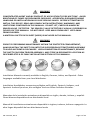
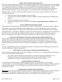
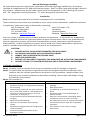
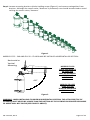
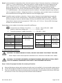
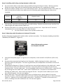
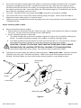
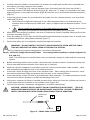
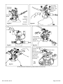
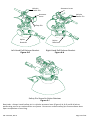
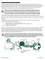
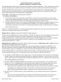
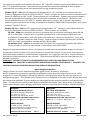
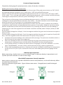
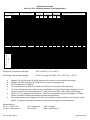
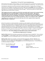
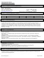
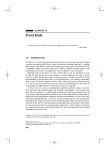
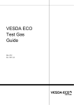
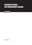
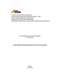
HFC 227ea
Model FG & FD Fire Extinguishers
Installation Instructions
Owner’s Manual
This manual is an integral part of the system approval and the extinguisher must be
installed and maintained in accordance with all listed requirements.
U.S. Coast Guard approved / FM approved
No. 162.029 / 237 / 0
Read and comply with these instructions, warnings and limitations before installing.
Suitable for use on:
FG Models:
0°F (-18°C) to 130°F (54°C)
FD Models:
20°F (-7°C) to 130°F (54°C)
Always maintain this owner’s manual
nearby for operator reference.
Owner’s Manual PN: 123-194, Revision E
Printed in the USA
WARNING
CONCENTRATED AGENT AND BY-PRODUCT OF APPLICATION TO FIRE ARE TOXIC. AVOID
BREATHING OF FUMES OR PROLONGED EXPOSURE. ACCIDENTAL DISCHARGE DURING
HANDLING OR INSTALLATION MAY CAUSE SERIOUS INJURY. BEFORE ATTEMPTING TO
INSTALL THIS DEVICE, READ AND COMPLY WITH INSTRUCTIONS, WARNINGS, AND
LIMITATIONS CONTAINED IN THIS MANUAL. DO NOT LIFT, CARRY OR HANDLE BY
SENSOR VALVE / DETECTOR. THE SENSOR / VALVE DETECTOR IS VISUALLY DESCRIBED IN
FIGURE 8 OF THIS MANUAL. DO NOT DROP. KEEP AWAY FROM HEAT. KEEP AWAY
FROM CHILDREN.
A MATERIAL SAFETY DATA SHEET (MSDS) IS INCLUDED IN THIS MANUAL.
WARNING
PRIOR TO PERFORMING MAINTENANCE WITHIN THE PROTECTED COMPARTMENT,
ALWAYS INSTALL THE SAFETY PIN INTO THE SUPPRESSION SYSTEM TRIGGER ASSEMBLY
TO AVOID ACCIDENTAL DISCHARGE. UPON COMPLETION OF MAINTENANCE, REMOVE
THE SAFETY PIN FROM TRIGGER ASSEMBLY, AND STORE IN DESIGNATED LOCATION AS
DESCRIBED STEP 6 OF CABLE INSTALLATION SECTION OF THIS MANUAL.
Installation Manuals currently available in English, German, Italian, and Spanish. Other
languages available from your local distributor.
Installation Handbücher momentan verfügbar auf Englisch, Deutsch, Italiener, und
Spanisch. Andere Sprachen, die verfügbar sind von Ihrem örtlichen Verteiler.
Manuales de la instalación actualmente disponible en inglés, alemán, italiano, y español.
Otros idiomas disponibles de su distribuidor local.
Manuali di installazione attualmente disponibile in inglese, tedesco, italiano e spagnolo. Le
altre lingue disponibili dal suo distributore locale
PN: 123-194, Rev E
Page 2 of 28
Index
Section
Warnings
Application/Limitations
System Operations
Pressure Switch
System Status Indicator Light
Pressure Relief Assembly (Burst Disk)
Engines and Powered Ventilation (Blowers)
Installation
Cylinder and Mounting Bracket
Cable Assembly
Indicator Light
System Maintenance
Cylinder Inspection/ Cylinder Testing
Agent Weight Inspection
Pressure Gauge Inspection
Indicator Light Inspection
Glass Bulb (Temperature Sensor/Detector) Inspection
Cable Inspection
Specification Tables
Specification Table “FG” Auto
Specification Table “FD” Auto
Warranty
MSDS – Heptafluoropropane
Notes
Contact Information
PN: 123-194, Rev E
Page(s)
Inside Cover
4
5
5
6
6
6
7 - 16
7-9
9 - 15
16
17 - 20
17 - 18
18
19
19
19
20
20 - 21
20
21
22
23 - 25
26 - 27
28
Page 3 of 28
Application
HFC-227ea (CF3CHFCF3), the extinguishing agent, used in all Sea-Fire “FG” and “FD” series fire
extinguishers, is a suitable EPA accepted alternate replacement for Halon. HFC-227ea is an
electrically nonconductive and residue free extinguishing agent that requires no cleanup.
These features and the versatility of design make the “FG” and “FD” series fire extinguisher models
ideal for a broad range of applications. These applications would include marine, commercial and
industrial use where electrical or flammable liquids are the likely source of fire.
Sea-Fire “FG” and “FD” series have passed a rigid testing program and carry a Factory Mutual Global
(FM) and United States Coast Guard (USCG) approval for fire suppression applications in marine
pleasure craft, un-inspected vessels, and Subchapter “T” inspected vessels, subject to the approval
of the local Officer in Charge, Marine Inspection (OCMI). This would include many applications such
as unoccupied engine and generator rooms, electrical compartments, paint and flammable storage
lockers.
Limitations
Sea-Fire “FG” and “FD” model series HFC-227 ea automatic fire extinguishers are designed and
tested to extinguish Class B (flammable liquid) and Class C (electrical) fires in enclosed
compartments only. Any openings (doors or hatches) will allow discharging agent to escape and will
seriously affect the ability of agent to extinguish the fire.
Sea-Fire “FG” and “FD” extinguishers are designed to induce a minimum atmospheric concentration
of 8.7 percent within the protected compartment. This is equivalent to a 30% safety factor on a
6.7% Minimum Extinguishing Concentration (MEC). In addition to gasoline and diesel fuel, other
flammable liquids with MEC values equal to or below 6.7% for HFC-227ea may be protected by SeaFire “FG” and “FD” systems.
The specification table in this manual lists the minimum and maximum approved compartment
volume (size) allowable for each model (per NFPA 2001, UL 2166, FM 5600*). Volume can be
determined by multiplying the compartment’s length x width x height which equals the volume in
cubic feet or meters (LxWxH=V).
*NFPA 2001: Standard on Clean Agent Fire Extinguishing Systems; UL 2166: Halocarbon Clean Agent
Extinguishing System Units; FM 5600: Approval Standard for Clean Agent Extinguishing Systems
Models described in this manual are stock available in 25 Cubic Feet (0.7 Cubic meters) intervals.
Systems are available in 1 Cubic Feet (0.03 Cubic meters) intervals if desired. Exact calculations
and/or measurements of the protected space should be accomplished if ordering these models. The
Specification Table shows the area of protection range available for ordering within each basic
model. For simplicity, throughout this manual, only the stock sizes will be noted.
“FG” and “FD” systems are designed for only one cylinder (single nozzle) to protect the entire space.
Using two cylinders to achieve combined coverage is not acceptable.
CAUTION: NEVER INSTALL A UNIT WITH A VOLUME RATING LESS THEN THE GROSS
VOLUME OF THE COMPARTMENT TO BE PROTECTED. DO NOT DEDUCT FOR ENGINES,
REMOVABLE TANKS OR OTHER EQUIPMENT.
Exception: If the boat manufacturer has placed a permanently affixed label in the engine
compartment specifying the gross volume less the volume of permanently installed tankage, then
this volume may be used to determine the proper size extinguisher. Check the specification table
for proper application before making installation.
PN: 123-194, Rev E
Page 4 of 28
Sea-Fire Marine offers all models compliant to applicable European Directives. Systems will be
shipped as requested. For orders requested compliant to CE directives, a Declaration of
Conformance (DOC) shall be included.
System Operations
Sea-Fire units described in this manual are automatically actuated by a temperature sensitive UL
listed glass bulb tested in accordance with UL 199. These bulbs are manufactured and tested to be
activated at a minimum temperature of approximately 175°F (79°C) when immersed in a liquid bath
or approximately 220°F (104°C) when tested using an air bath. The actual activation temperature of
the bulb in a fire scenario is influenced by numerous factors including air velocity, rate of
temperature rise, air flow, location, etc. The discharge temperature ranges (approximate) are shown
in the specification table, pages 20 – 21, and on the label attached to each unit.
These systems have been tested to United States Coast Guard (USCG), UL 2166 and FM 5600
requirements for Automatic Extinguisher Unit Automatic Operation Fire Tests.
* UL 199: Standard for Safety of Automatic Sprinklers for Fire Protection Service.
Discharge Temperature Ranges (approximate):
FG 25 – 75: 200 - 250°F (93 - 121 ºC)
FG 100 – 240: 175 - 225ºF (79 – 107ºC)
FD 150 – 1500: 175 - 225ºF (79 - 107ºC)
CAUTION: IN CASE OF SUPPRESSION SYSTEM DISCHARGE, DO NOT RUSH TO OPEN THE
PROTECTED COMPARTMENT. THE PROTECTED SPACE MUST BE KEPT CLOSED FOR AT LEAST
15 MINUTES TO ALLOW THE FIRE TO BE EXTINGUISHED AND SURFACES COOLED
SUFFICIENTLY TO PREVENT REFLASH. STOP BLOWERS AND SECURE HATCHES. HAVE A
PORTABLE EXTINGUISHER AVAILABLE AND USE CARE WHEN OPENING COMPARTMENT.
Avoid breathing fire related fumes or vapor.
Note: It is important to retain the designed vapor concentration within the compartment to insure
complete fire outage. Upon discharge, engines(s) and all powered ventilation (blowers) must be
shut down.
Supervisory Pressure Switch
Sea-Fire “FG” and “FD” series extinguishers are equipped with a factory installed pressure switch
which is intended for cylinder pressure supervision and may also be used to control other electrical
functions (engine shutdown, air exchange equipment etc.).
When using the pressure switch as an electrical disconnect for any equipment shutdown function, a
means of overriding (bypassing, shunting) the pressure switch must be provided in order to return
the affected equipment to an operational mode after extinguisher discharge has occurred. The
pressure switch is a single pole single throw (SPST) type that is normally closed (NC) with the system
in the charged condition. Discharge or loss of system pressure will release the contacts to an open
state thereby cutting off any electrical current flow.
Never use pressure switch for electrical loads over rated capacity.
Switch Specifications
4.0 AMPS at 12 VDC,
2.0 AMPS at 28 VDC
For applications requiring larger load capacities, contact the factory.
PN: 123-194, Rev E
Page 5 of 28
System Status Indicator Light Operation
All Sea-Fire pre-engineered fire suppression systems approved for marine applications are packaged
with an indicator light and faceplate. The indicator light (unless replaced by another Sea-Fire device:
i.e.: display panel) must be installed for system supervision and operator awareness. When
properly installed, activation of electrical power to the system will illuminate the light indicating
normal charge condition. System discharge or loss of pressure will immediately turn off the
indicator light. In the event that the indicator light is not lit when power is applied, check for the
following conditions:
1.
2.
3.
4.
Check pressure indicator gauge for proper range.
Check fuse and indicator light and replace if defective (lamp replacements available from
factory).
Check for loose electrical connections.
Remove and weigh system cylinder as described in System Maintenance Section of the
manual.
Pressure Relief Assembly (Burst Disk)
All models are protected from over pressure of system. FG Models 25 – 240 and FD 150 – 1000 are
protected by the design of the glass bulb temperature / pressure relationship. Sea-Fire Marine
maintains a Department of Transportation (DOT) Special Permit, DOT-SP-11598 for these models.
FD Models 1025 – 1500 have a definite purpose Pressure Relief Device (designed and manufactured
per CGA S.1-1) installed on the manifold. Do not remove or perform any maintenance on this
device. Removing or loosening this device will cause the contents under pressure to escape.
Interaction with Engines, Generators and Powered Ventilation (Blowers)
Sea-Fire offers optional engine interrupt systems which will automatically shut down engines,
generators and powered ventilation upon discharge of the fire suppression system. They are
available with 4, 6 or 8 control circuits and operate between 9 – 32 volts DC. Shutdown may be
accomplished by interruption of the electrical circuit between the ignition switch and the engine
coils.
It is the responsibility of the system designer/installer to comply with the following instructions on
Diesel and Gasoline Engines / generators.
Diesel Engines or Generators, Powered Ventilation (Blowers)
USCG, and American Boat and Yacht Council (ABYC) – Standard A-4, Fire Fighting Equipment (Section
A-4.7.3.3) both require the following:
The system shall be designed and installed so that the engine(s), generator(s), and
blower(s) located in the protected space shut down automatically and after
discharge the minimum required design concentration must remain.
Gasoline Engines or Generators
It is optional to automatically shut down gasoline engines and generators, but it is highly
recommended. In the case of engine compartment fire, you must still manually shut down engine(s)
or generator(s) before manual discharge, or immediately after automatic discharge of the fire
suppression system.
Relationship to Portable Fire Extinguishers
Reminder: Sea-Fire pre-engineered systems shall be considered as supplementary to the number of
portable fire extinguishers required on-board and are designed and intended for enclosed
unoccupied compartment installations that are not subject to direct weather or water.
PN: 123-194, Rev E
Page 6 of 28
Manual Discharge Capability
US Coast Guard approval requires the installation of manual discharge capability on all systems
installed in compartments of 1,000 cubic feet and larger. Sea-Fire offers manual discharge cables for
this purpose. Models with manual cable connections are designated as “M” following the system
size. “M” designates manual/automatic. “A” alone designates automatic only.
Installation
Read entire instruction manual and cylinder nameplate prior to installation.
These installation instructions are intended to cover most normal installations. Additional technical
or application information can be obtained by contacting:
Sea-Fire Marine - USA
Sea-Fire Europe, LTD
Baltimore, Maryland
or
Hampshire
Tel: 410 687-5500
United Kingdom
Website: www.Sea-Fire.co.uk
Website: www.Sea-Fire.com
Only one system (cylinder) may be used to protect a compartment. If more than one suppression
system is used to achieve the required amount of agent concentration, there is no guarantee that
several suppression systems will actuate simultaneously as each suppression system operates
independently. Several suppression systems may be used only if each independent suppression
system is capable of protecting the entire volume of the compartment.
CAUTION:
1. DO NOT INSTALL IN AN AREA DESIGNATED FOR OCCUPANCY.
2. ACCIDENTAL DISCHARGE MAY CAUSE SERIOUS INJURY.
3. HANDLE THE CYLINDER WITH EXTREME CARE.
4. WEAR EYE PROTECTION.
5. DO NOT LIFT OR CARRY CYLINDER BY THE MANIFOLD OR ACTUATOR COMPONENTS.
6. DO NOT ATTEMPT TO LOOSEN OR REMOVE ANY EXTINGUISHER COMPONENTS.
I. Cylinder Installation:
Step 1 Carefully remove cylinder from carton and visually check for damage in shipment.
Step 2 To ensure that the cylinder is operational, both the weight and pressure indicator must
conform with the cylinder specification as shown on the nameplate. Weigh cylinder (less
bracket) on an accurate calibrated scale before installing. Record date and weight on tag
provided for this purpose.
Step 3 Do’s and Don’ts
a.
b.
c.
d.
e.
f.
g.
Do place Unit:
As high as possible, no more than 3 feet
below the ceiling, on compartment bulkhead
for mounting.
With detector head near the area in which a
fire is most likely to occur. This would be on
the fuel line side of the engine, near the
carburetor, or fuel pump.
At the centerline of the bulkhead wall (left
to right).
Against forward bulkhead.
Vertical or horizontal as described per
model.
Between the engines when two engines are
to be protected.
Avoid immediate obstructions to the
discharge orifices.
PN: 123-194, Rev E
a.
b.
c.
d.
e.
f.
g.
Don’t place unit:
Near a fresh air or ventilation duct supply
opening.
Near access door.
To underside or inside of access door or
panel.
Extremely close to the turbocharger or
exhaust system.
Where an accumulation of standing water
could block sensor or cause corrosion.
On underside of cover or compartment hatch
that could be thrown clear due to possible
explosion.
Too close to a room corner or large
obstruction.
Page 7 of 28
Step 4 Loosen mounting bracket cylinder holding straps (Figure 1) and remove extinguisher from
bracket. Although the sensor valve / detector is protected, care should be exercised to avoid
striking the sensor valve / detector.
Figure 1
MODELS FG 25 - 240 AND FD 150 – FD 1000 MAY BE INSTALLED HORIZONTAL OR VERTICAL.
Horizontal or
Vertical
Mounting
MODELS FD 150
THRU 1000 AND FG
25 THRU 240
MAY BE MOUNTED
VERTICAL OR
HORIZONTAL
<90°
MODELS FD 1025
THRU FD 1500
MUST BE INSTALLED
VERTICAL ONLY
Figure 2
WARNING: WHEN INSTALLING CYLINDER IN HORIZONTAL POSITION, THE ACTUATOR (TOP OF
CYLINDER) MUST NEVER BE LOWER THAN THE BOTTOM OF THE CYLINDER OR PROPER DISCHARGE
OF AGENT WILL NOT OCCUR (SEE FIGURE 2 ABOVE).
PN: 123-194, Rev E
Page 8 of 28
Step 5 Locate bracket in desired position (Vertical-sensor Valve / Detector Head Up, or Horizontal,
Figure 2). Ensure bulkhead or mounting surface is solid enough to hold the weight of the
unit. Fasteners are not included. Use medium strength (Grade 5, Property Class 8.8) or
better grade material. Use minimum 5/16” (M8) diameter [recommend 3/8” (M10)
diameter] fasteners for all but 130-249 bracket assemblies. 130-249 minimum hardware size
is ¼” (M6) diameter. All mounting holes must be utilized. See table below for qty and hole
size in respective bracket. Using the bracket as a template, mark and drill holes in bulkhead
and install bracket ensuring that all fasteners are thoroughly tight.
Step 6 Carefully attach cylinder to bracket. Sensor valve / detector head should point towards
engine or center of the compartment. Nameplate and gauge should be visible. Tighten
bracket straps so that the cylinder body is firmly and securely held in place by its bracket
(worm drive clamps must be torqued to 75-85 in-lbs., (6-7 ft.-lbs.). Ensure 180° discharge
orifices do not face the wall.
Depending on the model, the bracket strap will be different:
Types
A Screw drive coil, Phillips / hex drive. ---------- FG 25 – 75 and FD 150 – 1000
B Buckle / wire form clamp style. ----------------- FG 76 – 240
C Two piece bracket / saddle assembly. --------- FD 1025 – 1500
Model
Brackets
Assembly
FD 150 - 225
FD 250 - 350
FD 375 - 500
FD 525 - 600
FD 625 - 1000
FD 1025 - 1500
130-250
130-251
130-252
130-253
130-254
130-009
Mounting Holes
(Qty x Dia)
4 x .39”
(9.9 mm)
13 x 7/16”
(10.7 mm)
Model
Brackets
Assembly
FG 25 - 75
130-249
FG 100
FG 125
FG 150 - 240
130-011
130-012
130-013
Mounting
Holes
(Qty x Dia)
2 x .29”
(7.2 mm)
4 x .281”
(7.1 mm)
II. Cable Assembly Installation
CAUTION: TO AVOID KINKING OF CABLE, DO NOT PUSH CABLE TO RETRACT THE CORE.
Note: Steps 2 and 6 show optional installations for 135-XXX or 136-XXX series cables.
CAUTION: TO PREVENT ACCIDENTAL DISCHARGE DURING CABLE INSTALLATION, VERIFY
THAT THE MANUAL DISCHARGE LEVER SAFETY PIN IS PROPERLY INSTALLED.
Step 1 Select the proper location for remote pull station.
a.
b.
c.
Manual discharge release pull stations should never be installed in the protected compartment.
Locate discharge pull handle at the helm station with full view and easy access by the operator.
The area selected must be structurally secure and provide at least twelve (12) inches (305 mm)
of clearance at the rear of the panel to facilitate cable hardware.
PN: 123-194, Rev E
Page 9 of 28
Step 2 Installing cable along routing between cable endsa.
b.
Do not install cable in area where the possibility of physical abuse is likely. Where practical,
follow the same cable path as installed by boat manufacturer (if a replacement cable).
Route the cable to allow it to lie in its most natural state. The cumulative bends in the cable run
and minimum bend radius must adhere to the following table depending on cable series
installed:
Cable
Series
135-X##
136-X##
c.
d.
Maximum Cumulative
bends
(Degrees)
360
720
Maximum No. of 90
degree bends
Minimum Bend Radius
4
8
12 in (305 mm)
5 in. (127mm)
Use extreme care when bending cable to avoid kinking. Selection of the correct size Sea-Fire
cable length will reduce excess cable coil.
Position the cable in its routing, but do not secure at this time. Steps 3A thru 3F must be
completed prior to securing cable in its final location.
•
Do not connect cable to the cylinder at this time.
Step 3 Mounting cable faceplate and release (T) handle.
Confirm faceplate supplied with cable and/or cylinder assembly. The faceplate heading should be
“MANUAL/AUTOMATIC” (Figure 3).
Manual/Automatic systems
use faceplate 124-026
Figure 3
a.
b.
c.
d.
Using the faceplate (Figure 3, Figure 4) as a template, mark and drill a 13/32inch (10.4 mm)
hole.
Remove the protective backing from the faceplate. While aligning the holes, place even
pressure upon the faceplate. To insure a good bond, the temperature should be in excess of
50°F (10°C).
Following the diagram in Figure 4, install the jam nut and lock washer on the cable end – outer.
Screw the jam nut to the end of the threads. Insert the cable end through the panel and
faceplate hole. Pull the cable end – inner (threaded shaft) out to its fullest travel. Install ferrule
by screwing onto the cable end – outer until it bottoms out. Use pliers on the back side –
holding the cable end – outer while turning the ferrule. Use pliers with rubber tips or other
non-scratching grip. Do not over tighten.
With cable end – inner (threaded shaft) out to its fullest travel, place rubber O-ring over
threads on shaft. Hold the cable end-inner from rotating using the Safety pin in cross hole (see
Figure 4 – Page 11) or by using needle nose pliers. Install the T- Handle on the cable end –
inner, screwing it on until it bottoms out. Do not over tighten.
PN: 123-194, Rev E
Page 10 of 28
e.
f.
g.
h.
Pull on the cylinder (S-hook) end of the cable to retract the handle into the ferrule. It may be
necessary to slightly push on the T-handle to seat the O-ring. Align the cross holes in the THandle and ferrule and insert the safety pin through both items so that the end of the safety
pin shows out the far side. Leave the safety pin inserted through the T-handle/Ferrule, but do
not install the red safety tie at this time.
Turn the T-handle/Ferrule so that the word FIRE is vertical or oriented as needed.
This action will result in the entire cable rotating along its length. Ensure that the cable is
allowed to rotate and remain in a natural state.
Tighten the jam nut behind the instrument panel to lock in the position and orientation of the
T-handle/Ferrule.
Step 4 Securing cable in place
a.
Secure the cable along its length.
i. Nylon cable ties should be used for cable securing. Fasten and support the cable on straight
runs only. Do not secure at locations where cable bends.
ii. At the cylinder/actuator S-Hook end:
a. The cable should have a minimum straight length of 6 inches (15 cm) before making any
bends. The cable should be secured on a straight run before making a bend.
b. The cable should be secured within 6 inches to 18 inches (15 cm – 46 cm) of the cylinder.
Some flexibility will be needed to move the cable for servicing the cylinder.
CAUTION: FAILURE TO FOLLOW THESE INSTRUCTIONS MAY PLACE UNDUE
PRESSURE ON THE HAIRPIN COTTER PIN, CAUSING IT TO MALFUNCTION.
iii. Do not install cables with other wiring. Do not use tie wire around the cables.
b.
Temporarily remove safety pin and test cable operation. Never push cable. Pull from cylinder
(S hook) end, then, pull T handle and repeat. Cable must move freely without friction or
binding. Reinstall safety pin and confirm that release handle is now locked in place.
Cable End Inner
Instrument
Panel
Face Plate
Cable End
Outer
Cross Hole
Nut
Ferrule
Washer
T-Handle
Safety Pin
O-ring
Figure 4
PN: 123-194, Rev E
Page 11 of 28
CAUTION: ACCIDENTAL DISCHARGE DURING HANDLING OR INSTALLATION MAY CAUSE
SERIOUS INJURY. DO NOT REMOVE FACTORY INSTALLED SAFETY (PULL) PIN FROM
CYLINDER SENSOR VALVE / DETECTOR UNTIL INSTALLATION IS COMPLETED AND
CHECKED.
Step 5 Installation Verification and Test Requirement.
Specification / Regulation
•
U.S.C.G – Navigation and Vessel Inspection (NVIC 6-72, Section V, Page 71) requires a maximum
of 40 lbs. of force required at T handle (pull station) to activate system discharge.
•
NFPA 12A - Operating devices. Para. 1-8.3.7 maximum of 40 lbs. of force required at T handle
(pull station) to activate system discharge.
•
Sea-Fire - minimum of 10 lbs. of force required at the S hook (extinguisher) to activate system
discharge.
Test Procedure
CAUTION: DO NOT PUSH (FIRE) T-Handle while installing cable assembly to avoid kinking the
cable core. Pull S-Hook at opposite end to retract the T-Handle.
After the initial routing of cable assembly is completed:
a. Attach a scale (PN: 128-212 Cable Test Fixture) to the S-hook (cylinder end) in place of the
cylinder Release assembly.
b. Attach a scale (PN: 128-092 Digital Scale) to the T-handle (pull station) end of the cable
assembly. A handle hook, PN: 128-115 is available to facilitate attaching the scale. (Scales
available from Sea-Fire or others may be used)
c. Pull on the T-handle scale, monitoring the displayed force, until 10 lbs (4.5Kg) is shown on the
S-hook (cylinder end) scale.
d. Ensure that the required force at the T-handle (pull station) does not exceed 40 Ibs. (18.2 Kg) to
achieve 10 lbs. (4.5 Kg).
i. If less than 40 lbs. (at the pull station) of force achieves the 10 lbs. (at cylinder), complete
the cable assembly installation per Step 6.
ii. If greater than 40 Ibs. of force was exerted to achieved 10 lbs., the cable routing should be
inspected and likely changed. Repeat inspection.
e. Remove both scales. Pull on the S-Hook at the cylinder to retract the cable.
f. Reinstall safety pin and confirm that release handle is now locked in place.
g. Attach the tamper resistant round plastic tie to the safety pin by passing tie through the safety
pin ring and around the cable assembly. Insert the end of the tie into cable end and pull up
snug. The tie provides a means of deterring accidental discharge and determining if manual
actuation has occurred.
CAUTION: DO NOT USE NYLON CABLE TIES IN PLACE OF THE TAMPER RESISTANT TIE FOR
SAFETY PIN.
Note: Limit the quantity, and tightness of tie downs to avoid restriction.
Note: The maximum of bends/ turns, and minimum bend radius per turn as outlined in step 2(b)
must be followed.
Step 6: 136 Series (Bi-directional) Cables
Connecting cable assembly to cylinder (Figure 6A-6F).
Note: The cable may be installed from either direction using the existing Bi-Directional
hardware installed on the system.
PN: 123-194, Rev E
Page 12 of 28
a.
b.
c.
d.
e.
f.
Confirm that the cylinder is mounted in its bracket, the cable pull handle end is installed and
the cable is correctly routed to the cylinder.
Insert the “S” hook [Fig 5-A] into the actuator lever from the front side (over top of the 2
mounting screws in the Release Bracket [Fig 6-B]. After the “S” hook is connected to the lever,
align the groove in the cable end-outer [Fig 5-B] with the slot in the Release Bracket assembly
[Fig 6-C].
Insert the Hairpin Cotter Pin provided with the cable into the release bracket, over top of the
cable end [Fig 6-D].
• There may be a slight bend (bump) in the cable between where it is attached to the
actuator lever and where the cable end - outer is clipped into the Release Bracket. This is
normal.
•
There should not be tension in the cable pulling on the lever. Tension on the lever
can cause the cylinder to discharge when the safety pin is removed.
With Step c successfully complete, use care to remove the factory installed safety pin from the
actuator assembly [Fig 6-E].
Store the safety pin in the hole of the Release Bracket behind the actuator lever as a back-stop
in farthest hole from cable/hook assembly [Fig 6-F].
Ensure the safety pin is completely installed through the bracket.
WARNING – DO NOT INSTALL THE SAFETY PIN BETWEEN THE LEVER AND THE CABLE.
THIS WILL PREVENT THE CABLE FROM ACTUATING THE SYSTEM.
g. The fire suppression system extinguisher is now fully operational.
Step 6: 135 Series (Single-directional) Cables Connecting cable assembly to cylinder (Figure 6-G,
6-H, and 6-I).
Note: The cable may be installed from only one direction using this cable and the mounting
system.
a.
b.
c.
d.
e.
f.
Before attaching cable to the cylinder, check that the cylinder bracket is located correctly and
firmly mounted and the actuator lever safety pin is inserted.
With the cylinder strapped in its bracket, pass the S-Hook and the outer cable conduit - cable
end completely through the hole in the release bracket.
Insert the S-Hook through the hole in the actuator lever. After making this connection, move
the cable end back and align the groove with the slot in the release bracket.
Insert the Hairpin Cotter Pin that is provided with cable assembly. The cable assembly must be
locked to the release bracket or accidental discharge can occur.
Using care, remove the factory installed actuator lever safety pin from the cylinder and store it
in the nylon retainer provided on the cylinder neck (Figure 6-I).
The Sea-Fire manual / automatic extinguisher is now fully operational.
CAUTION – ALWAYS INSTALL SAFETY PIN IN CYLINDER ACTUATOR LEVER [FIG 6-A]
WHEN PERFORMING SERVICE OR MAINTENANCE ON SYSTEM. BE SURE TO REMOVE
SAFETY PIN FROM ACTUATOR LEVER UPON COMPLETION OF SERVICING.
Cable End
Outer
B
S-Hook
A
Figure 5 -- SMAC Cable S-Hook End
PN: 123-194, Rev E
Page 13 of 28
Carefully
Insert “S”
Hook into
Release
Arm
Release
Bracket
Cylinder
Head
Fig 6-A
Safety
Pin is
Located
in
Center
Position
Fig 6-B
Lock Cable
in Place with
Hairpin
Cotter Pin
Fig 6-C
Fig 6-D
Locate Pin
Behind
Release Arm
as a Backstop
in Farthest
Hole from
Cable/ Hook
Assembly
Fig 6-E
Release Arm
Fig
6-F
Bi Directional Release Bracket Cable Connection
PN: 123-194, Rev E
Page 14 of 28
Actuator Lever
Hairpin
Cotter Pin
Hairpin
Cotter Pin
Actuator
Lever
Safety Pin
Nylon
Retainer
Nylon
Retainer
Left Hand Pull Release Bracket
Figure 6-G
Right Hand Pull Release Bracket
Figure 6-H
Safety Pin Stored in Nylon Retainer
Figure 6-I
Reminder: Always install safety pin in cylinder actuator lever (Figure 6-A, 6-G and 6-H) when
performing service or maintenance on system. Be sure to remove safety pin from actuator lever
upon completion of servicing.
PN: 123-194, Rev E
Page 15 of 28
III. System Status Indicator Light Installation
Select a location at the helm on or near the console that is in full view of the helmsman. The
location selected must have access for electrical wiring. Remove the adhesive protective cover from
back of indicator faceplate and attach. For proper adhesion, surface must be clean and dry and
temperature must be above 50ºF (10ºC). Use the preformed faceplate hole as a template and
carefully drill a 5/16 inch (8 mm) hole. Insert indicator light wire (see Figure 7).
CAUTION: PRIOR TO WIRING INDICATOR LIGHT, TURN OFF ELECTRICAL POWER BY
SWITCHING OFF CIRCUIT BREAKER, REMOVING FUSE OR DISCONNECTING POSITIVE
BATTERY TERMINAL. FAILURE TO DISCONNECT ELECTRICAL POWER WHILE MAKING
ELECTRICAL CONNECTION CAN RESULT IN INJURY FROM FIRE OR ELECTRICAL BURNS.
The standard indicator light is rated for 12 VDC (contact factory for other voltages). Wire in
accordance with the American Boat and Yacht Council (ABYC), Standard E-9, Direct Current Electrical
System on Boats, copies of which may be obtained from ABYC, Edgewater, MD, USA, 21037, +1 (410)
956-1050.
Supplies, which are not included with your Sea-Fire system and should be at hand before the
indicator light installation, are as follows:
1. Five (5) ampere in-line fuse and holder.
2. Sufficient length of insulated minimum 16 AWG stranded wire.
3. Crimp on wire connectors.
4. Crimp pliers, hand tools.
Attach one wire lead from the in-line fuse (C) to the ignition terminal on the started switch. Connect
other lead from the in-line fuse to the indicator light (D). Connect remaining indicator lead (E) to
one of the Sea-Fire cylinder pressure switch connector wires (F). Connect the remaining cylinder
pressure switch lead (G) to common ground, which may be the negative battery bus at the control
panel, or directly to the engine block (see Figure 7).
CAUTION: ELECTRICAL SYSTEMS VARY FROM VESSEL TO VESSEL AND THESE DIRECTIONS
MAY NOT BE APPLICABLE FOR YOUR INSTALLATION. SHOULD YOU HAVE ANY DOUBTS OF
SAFELY ACCOMPLISHING THIS INSTALLATION, CONTACT A QUALIFIED MARINE ELECTRICIAN
OR SEA-FIRE MARINE USA AT (410) 687-5500 FOR TECHNICAL ASSISTANCE.
Indicator Light
F
E
Starter
D
Ignition
Switch
Ignition
C
In-Line Fuse
G
Negative Battery
Ground
Figure 7
PN: 123-194, Rev E
B
A
Battery +/-
Page 16 of 28
System Maintenance / Inspection
Cylinder Inspection / Cylinder Testing
The following instructions are according to applicable regulatory agencies. These regulations change
periodically and may be different from rules in place when this system and manual were shipped.
Confirm requirements with Sea-Fire, local authorities having jurisdiction or applicable agency. All
inspections must be performed by an authorized/Qualified inspector (Current RIN for DOT) and
other requirements per local authorities as applicable.
NFPA 2001 – Clean Agent Fire Extinguisher Systems:
All models, all cylinders:
• If more than 5 years has elapsed since the date of the last test and inspection, the cylinder
shall not be recharged without retesting. The test shall be permitted to consist of a complete
visual inspection as described in 49 CFR (explained below per cylinder type).
• Cylinders continuously in service without discharging shall be given a complete external visual
inspection every 5 years or more frequently if required. The visual inspection shall be in
accordance with Section 3 of CGA C-6, except that cylinders need not be emptied or stamped
while under pressure.
49 CFR – Transportation (DOT) – Cylinder Requalification (Hydrostatic testing via proof pressure and
volumetric testing; visual inspection methods)
Models FG 25 – 240 built with DOT 39 NRC/TC-39M cylinders:
These are non-refillable and are non-reusable. They do not require/ are not allowed to be tested for
re-use. The systems may remain in service indefinitely as long as all other serviceability
requirements are met. Systems with these cylinders, per 49 CFR requirements, are clearly marked,
“Federal law forbids transportation if re-filled – penalty up to $500,000 fine and 5 years
imprisonment (49 U.S.C. 5124).
Models FD 150 – 1000 built with DOT 3AL/TC-3ALM cylinders and FD Models 1025 – 1500 built with
DOT 4BW/TC 4BWM welded steel cylinders:
Both of these cylinder types are reusable and must be periodically tested and re-qualified. The
periodic inspection interval for both DOT 3AL and DOT 4BW cylinders filled as a Fire suppression
system with the agent as supplied is 12 years from the date stamped on the cylinder. However, a
cylinder filled before its re-qualification date (becomes due), and remains filled, may remain in
service without testing until it is emptied for any reason (reference 49 CFR 180.205 (c).
• Correlation to NFPA 2001 (5 year) requirement. In both standards, if the cylinder is not already
empty, it does not need to be emptied solely for inspection purposes. If the cylinder has more
than 5 years of service, and has been emptied for whatever reason, it needs to be inspected per
NFPA 2001 guidelines listed above.
• For DOT 4BW/ TC 4BWM welded steel cylinders only, a visual inspection in accordance with
CGA C-6 or C-6.3, as appropriate, may be performed instead of the periodic hydrostatic tests.
When this test method is applied, the subsequent inspection comes due after 5 years.
o Applicable tests methods for DOT 4BW cylinders are by Proof Pressure Test which yields a
subsequent test requirement after 7 years and a Volumetric Expansion test using the
Water Jacket Method which yields a subsequent test requirement after 12 years.
• For DOT 3AL/TC 3ALM cylinders, visual inspections are not authorized to replace hydrostatic
testing.
o The only test method for DOT 3AL cylinders is the Volumetric Expansion test using the
Water Jacket Method which yields a subsequent test requirement after 12 years.
PN: 123-194, Rev E
Page 17 of 28
For systems compliant to European Directives, (EC), specific cylinders may be used different than
DOT / TC approved systems. International requirements need to be followed as well as other
requirements according to the local authorities having jurisdiction (AHJ).
Models FG 25 – 240 with EC approval are designated as “CE” marked in accordance with the
Pressure Equipment Directive (PED) 97/23/EC. Those cylinders are built to technical specifications
either BS EN12205 or ISO 11118. These systems are not refillable. Systems with these cylinders
are not serviceable and therefore have no periodic inspection requirements. (Reference ISO
11118 and PED Directive 97/23/EC). Models with these cylinders, per European Agreement
Governing the International Carriage of Dangerous Goods by Road (ADR) requirements, are clearly
marked, “DO NOT REFILL”.
Models FD 150 – 1500 with EC approval are designated as “CE” marked in accordance with the
Pressure Equipment Directive (PED) 97/23/EC. These systems are refillable.
FD 150 – 1000 have seamless aluminum cylinders built to technical standards either BS EN
1975 or ISO 7866. Systems with π marked cylinders built to ISO standard 7866 are to be
maintained in accordance with ISO 10461, Gas Cylinders – Seamless Aluminum – Alloy Gas
Cylinders – Periodic Inspection and Testing. Systems with π marked cylinders built to BS EN
1975 are to be maintained in accordance with BS EN 1802.
FD Models 1025 – 1500 have welded steel cylinders built to technical standard EN 13322-1.
These cylinders need to be maintained in accordance with BS EN 1803.
Summarizing these standards, there is no general requirement to periodically inspect a cylinder if
the contents have not been used, even if the test interval has lapsed. In the event that contents
have discharged, leaked or otherwise been exhausted, the inspection interval is 10 years from the
manufacture date stamped on the cylinder. TPED Directive 96/36/EC also has requirements for
periodic inspection.
WARNING: DO NOT ATTEMPT TO DISASSEMBLE ANY PART OR COMPONENT OF THE
EXTINGUISHER. THIS UNIT IS PRESSURIZED AND SERIOUS INJURY COULD RESULT. CONTACT THE
FACTORY OR AN AUTHORIZED DEALER FOR SERVICE INFORMATION.
Agent Weight Inspection
Weigh cylinder to insure ample extinguisher agent (every 6 months, minimum).
All fire suppression systems containing liquefied gas require periodic weighing to ensure a fully
charge unit. Pressure gauges indicate the ability to discharge the agent but not the quantity of
extinguishing agent. The cylinder (less bracket) must be weighed on at least a semi-annual basis and
be replaced immediately if gross weight has decreased by the quantity noted on the specification
label. The specification label (shown below) identifies the Model Type, Work Order #, Discharge
Temperature Range, Agent Weight, Maximum Volume Protected, Gross Weight, and Manufacturer
Date:
W.O.XXXXXX
W.O.XXXXXX
MODEL
MODEL
FG XXXA AUTOMATIC
FD XXXM MANUAL/AUTO
DISCHARGE TEMPERATURE RANGE:
175 - 225 F (79 - 107 C)
CONTAINS: X.XX LBS (X.XKG) FM200
DISCHARGE TEMPERATURE RANGE:
XXX - XXX F (XX - XXX C)
CONTAINS: X.XX LBS (X.XKG) FM200
GROSS WEIGHT
XX LBS. X OZS. (XX KGS)
GROSS WEIGHT
XX LBS. X OZS. (XX KGS)
MAXIMUM VOLUME PROTECTED
XXX CU. FT. (X.X CU. METERS)
REPLACE IMMEDIATELY IF GROSS WEIGHT
DECREASES BY X OZS. OR MORE
MANUFACTURE DATE: XX/XXXX
PN: 123-194, Rev E
REV: X
MAXIMUM VOLUME PROTECTED
XXX CU. FT. (X.X CU. METERS)
REPLACE IMMEDIATELY IF GROSS WEIGHT
DECREASES BY X OZS. OR MORE
MANUFACTURE DATE: XX/XXXX
REV: X
Page 18 of 28
Pressure Gauge Inspection
Frequently check gauge for proper pressure, (every 6 months, minimum).
Reading the Pressure Gauge (Inspection)
The green section of the gauge is designed to show proper filling and pressurization at 70°F (21°C).
Per applicable design standards, this is defined as ± 10% of nominal fill pressure.
Sea Fire systems are rated for operating temperatures from 0°F (-17°C) or 20°F (-6°C) up to 130°F
(54°C). Note: This is storage and ambient operating temperature. A fire condition would obviously
reach higher temperatures, with the system activating at 175°F (79°C).
The red section of the gauge, above and below the green section, indicate the acceptable pressure
readings for temperatures below and above 70°F (21°C). The table located on the included tags
show the pressure of the system at corresponding temperatures.
To inspect a unit when the ambient temperature is other than 70°F (21°C), measure the ambient
temperature and find the corresponding nominal pressure in the table. Read the tip of the yellow
pointer and determine what the internal pressure is by counting the division lines and adding or
subtracting for each line segment from the black centerline marked, either 240 psi (16 bar) or 360
psi (24 bar).
For FG models (charged to 240 psi): Each line segment within the green and red zones are equal to
20 psi (1 bar).
For FD models (charged to 360 psi): Each line segment within the green pie is equal to 10 psi (0.68
bar). Each line segment within the red sections is equal to 20 psi (1 bar).
•
Compare the actual reading to the reference table (see tag). The pressures should be within ±
20 psi (1 bar) of each other (one segment).
•
Note: this allowance takes into account allowing for gauge manufacturing tolerance,
temperature reading accuracy and the ability to precisely see the pointer location.
•
If the yellow pointer is in either the white zone on the gauge, to the left “REPLACE” or to the
right “OVERCHARGE”, the unit is likely not functional and may require replacement.
•
If time and serviceability permits, a suspect unit may be verified by stabilizing the temperature
of the unit at 70°F (21°C) for a minimum of 4 hours and reading the pressure gauge at that
point.
Indicator Light Inspection
Before operating, visually check to insure indicator light or alternate display is operational, and
cylinder pressure indicator is in the normal range.
Glass Bulb (Temperature Sensor) Inspection
Never paint or obstruct the cylinder manifold or sensor valve/detector, as this will adversely affect
its operating characteristic.
Check for presence of glass bulb. Figure 8 shows two states: Charged (Intact) and Discharged
(Activated).
Detectors
Charged
Discharged
Figure 8
PN: 123-194, Rev E
Page 19 of 28
Cable inspection
Manual activation cables should be checked for proper operation every 6 months while cylinder
inspection is being performed. Cable runs should be visually checked to ensure no damage has been
done to the cable. (No excessive wear or pinching exists).
Take safety pin out of ‘backstop’ position in the release bracket and place into center hole, securing
release arm. Disengage ‘S’-hook from release arm, remove pin from fire release handle, and test
cable for smooth operation. Re-assemble in reverse order (see Figure 6, page 14).
Additional Servicing
Further servicing of Sea-Fire pre-engineered systems is reserved to competent individuals who have
completed training by Sea-Fire Marine personnel and Service Manual 123-253 is available to these
individuals.
Specification Table
Sea-Fire “FG” Series Automatic Fire Extinguishers
Minimum HFC- Maximum HFC227 ea
227 ea
FG Model
Man /
Auto
Auto
FG 25A
FG 25M
FG 50A
FG 50M
FG 75A
FG 75M
FG100A
FG100M
FG125A
FG125M
FG150A
FG150M
FG175A
FG175M
FG200A
FG200M
Area of Protection
CU FT
CU M
Range
Range
22-25
0.62-0.7
30-50
0.85-1.4
51-75
1.4-2.1
76-100
2.1-2.8
101-125
2.8-3.5
135-150
3.8-4.2
151-175
4.2-5.0
176-200
5.0-5.7
FG225A
FG225M
201-225
5.7-6.4
8.7
3.9
9.7
FG240A
FG240M
226-240
6.4-6.8
9.7
4.4
10.4
LBS
0.95
1.3
2.2
3.3
4.3
5.4
6.5
7.6
KG
LBS
0.43
1.1
0.58
2.2
1
3.3
1.5
4.3
2
5.4
2.5
6.5
3
7.6
3.5
8.7
Cylinder
Diameter
KG
IN
0.5 2.9
1 2.9
1.5 3.5
2 3.5
2.5 4.25
3 5.25
3.5 5.25
3.9
5.25
4.4
5.25
4.7 5.25
Installation Dimension Requirements
W
H
D
MM
IN
MM
IN
MM
127
11.9
302
4.3
109
127
15
381
4.3
109
127
17.8
452
4.4
112
127
18.1
460
4.5
114
127
18.2
462
5.1
130
140
19.8
503
6.1
155
140
19.8
503
6.1
155
MM
74
74
89
89
108
133
133
IN
5
5
5
5
5
5.5
5.5
133
5.5
140
19.8
503
6.1
155
133
5.5
140
19.8
503
6.1
155
133
5.5
140
19.8
503
6.1
155
Operating Temperature Range:
0°F to 130°F (-18°C to 54°C)
Discharge Temperature Range:
FG 25 through FG 75: 200 - 250°F (93 - 121°C)
FG 100 through FG 240: 175 - 225°F (79 - 107°C)
•
•
•
•
•
All FG Models approved for vertical or horizontal mounting.
All FG Models are available with multiple approved cylinders, DOT/TC and CE.
All FG Models are non-refillable (non-serviceable)
ABYC, A-4, Fire Equipment Standard: Fixed fire extinguishing systems (August 1, 2009)
shall be capable of both Automatic and Manual operation.
FG model systems are designed for only one cylinder (single nozzle) to protect the entire
space. Using two cylinders to achieve combined coverage is not acceptable.
Abbreviations:
CU FT = Cubic Feet
CU M = Cubic Meters
PN: 123-194, Rev E
KG = Kilograms
LBS = Pounds
IN = Inches
MM = Millimeters
Page 20 of 28
Specification Table
Sea-Fire “FD” Series Automatic Fire Extinguishers
FD Model
Auto
FD 150A
FD 175A
FD 200A
FD 225A
FD 250A
FD 275A
FD 300A
FD 325A
FD 350A
FD 400A
FD 450A
FD 500A
FD 550A
FD 600A
FD 650A
FD 700A
FD 750A
FD 800A
FD 850A
FD 900A
FD 950A
FD1000A
V
E
R
T
I
C
A
L
M
O
U
N
T
I
N
G
O
N
L
Y
Area of Protection
Minimum HFC- Maximum HFC227 ea
227 ea
Cylinder
Diameter
Man /
Auto
CU FT
Range
CU M
Range
LBS
KG
LBS
KG
IN
MM
FD 150M
FD 175M
FD 200M
FD 225M
FD 250M
FD 275M
FD 300M
FD 325M
FD 350M
FD 400M
FD 450M
FD 500M
FD 550M
FD 600M
FD 650M
FD 700M
FD 750M
FD 800M
FD 850M
FD 900M
FD 950M
FD1000M
FD1050M
FD1100M
FD1150M
FD1200M
FD1250M
FD1300M
FD1350M
FD1400M
FD1450M
FD1500M
126-150
151-175
176-200
201-225
226-250
251-275
276-300
301-325
326-350
351-400
401-450
451-500
501-550
551-600
601-650
651-700
701-750
751-800
801-850
851-900
901-950
951-1000
1001-1050
1051-1100
1101-1150
1151-1200
1201-1250
1251-1300
1301-1350
1351-1400
1401-1450
1451-1500
3.5-4.2
4.2-5.0
5.0-5.7
5.7-6.4
6.4-7.1
7.1-7.8
7.8-8.5
8.5-9.2
9.2-9.9
9.9-11.3
11.3-12.7
12.7-14.2
14.2-15.6
15.6-17.0
17.0-18.4
18.4-19.8
19.8-21.2
21.2-22.7
22.7-24.1
24.1-25.5
25.5-26.9
26.9-28.3
28.3-29.8
29.8-31.1
31.1-32.6
32.6-34.0
34.0-35.4
35.4-36.8
36.8-38.2
38.2-39.6
39.6-41.1
41.1-42.5
5.4
6.5
7.6
8.7
9.7
10.8
11.9
13
14
15.2
17.3
19.5
21.7
23.8
26
28.1
30.3
32.5
34.6
36.8
39
41.1
43.3
45.5
47.6
49.8
52
54.1
56.3
58.5
60.6
62.8
2.4
2.9
3.4
3.9
4.4
4.9
5.4
5.9
6.4
6.9
7.8
8.8
9.8
10.8
11.8
12.7
13.7
14.7
15.7
16.7
17.7
18.6
19.6
20.5
21.6
22.6
23.6
24.5
25.5
26.5
27.5
28.5
6.5
7.6
8.7
9.7
10.8
11.9
13
14
15.2
17.3
19.5
21.7
23.8
26
28.2
30.3
32.5
34.6
36.8
39
41.1
43.3
45.5
47.6
49.8
52
54.1
56.3
58.5
60.6
62.8
65
2.9
3.4
3.9
4.4
4.9
5.4
5.9
6.4
6.9
7.9
8.7
9.8
10.8
11.8
12.8
13.8
14.8
15.8
16.7
17.7
18.7
19.7
20.7
21.7
22.6
23.6
24.6
25.6
26.6
27.6
28.5
29.5
5.2
5.2
5.2
5.2
6.9
6.9
6.9
6.9
6.9
6.9
6.9
6.9
6.9
6.9
8
8
8
8
8
8
8
8
10
10
10
10
10
10
10
10
10
10
132
132
132
132
175
175
175
175
175
175
175
175
175
175
203
203
203
203
203
203
203
203
254
254
254
254
254
254
254
254
254
254
Installation Dimension Requirements
H
W
D
IN
MM
IN
MM
IN
MM
6.2
6.2
6.2
6.2
7.4
7.4
7.4
7.4
7.4
7.7
7.7
7.7
7.6
7.6
8.6
8.6
8.6
8.6
8.6
8.6
8.6
8.6
16.3
16.3
16.3
16.3
16.3
16.3
16.3
16.3
16.3
16.3
157
157
157
157
188
188
188
188
188
196
196
196
193
193
218
218
218
218
218
218
218
218
414
414
414
414
414
414
414
414
414
414
19.9
19.9
19.9
19.9
19.2
19.2
19.2
19.2
19.2
23.8
23.8
23.8
27.8
27.8
28.1
28.1
28.1
28.1
32.9
32.9
32.9
32.9
30
30
30
30
30
30
30
30
30
30
505
505
505
505
488
488
488
488
488
605
605
605
706
706
714
714
714
714
836
836
836
836
762
762
762
762
762
762
762
762
762
762
6.1
6.1
6.1
6.1
8
8
8
8
8
7.8
7.8
7.8
7.8
7.8
9.2
9.2
9.2
9.2
9.2
9.2
9.2
9.2
11.1
11.1
11.1
11.1
11.1
11.1
11.1
11.1
11.1
11.1
155
155
155
155
203
203
203
203
203
198
198
198
198
198
234
234
234
234
234
234
234
234
282
282
282
282
282
282
282
282
282
282
Operating Temperature Range:
20°F to 130°F (-7°C to 54°C)
Discharge Temperature Range:
FD 150 through FD 1500: 175 - 225°F (79 - 107°C)
•
•
•
•
•
•
•
Models FD 150 through FD 1000 approved for vertical or horizontal mounting.
Models FD 1050 through FD 1500 are for vertical mounting only.
All FD models are refillable.
FD models are only offered in either US DOT/TC or European CE (not both).
US Coast Guard approval requires the installation of manual discharge capability on all
systems installed in compartments of 1,000 cubic feet (28.3 cubic meter) and larger.
ABYC, A-4, Fire Equipment Standard: Fixed fire extinguishing systems (August 1, 2009)
shall be capable of both Automatic and Manual operation.
FD model systems are designed for only one cylinder (single nozzle) to protect the entire
space. Using two cylinders to achieve combined coverage is not acceptable.
Abbreviations:
CU FT = Cubic Feet
CU M = Cubic Meters
PN: 123-194, Rev E
KG = Kilograms
IN = Inches
LBS = Pounds
MM = Millimeters
Page 21 of 28
Three (3) Year “FG” and “FD” Series Limited Warranty
We warrant to the original retail purchaser, the FD and FG suppression systems for a period of three
(3) years after retail purchase against defective material and faulty workmanship. Any system found
to be defective during the warranty period will repaired if possible, or replaced free of charge if
classified as non-refillable (according to the product label) upon the prepaid return of the defective
system to Sea-Fire facility or authorized service party. Proof of purchase required, otherwise date of
manufacturer on extinguisher specification label will apply. This warranty gives you specific legal
rights which may vary by state or country.
The foregoing warranty is made in lieu of all other warranties with respect to the system including
any implied warranty of merchantability or fitness for a particular purpose. No person is
authorized to give any other warranty, or assume for Sea-Fire Marine any other liability in
connection with the sale or installation of its products. Replacement of the system will be the sole
remedy with respect to any loss or damage to property. Buyer is not relying on seller’s judgment
regarding buyer’s particular requirements and buyer has had an opportunity to inspect the
product to buyer’s satisfaction.
Conditions
All Sea-Fire products are leak tested after manufacture and shipped in perfect working order.
Damage noted upon receipt of shipment should be addressed as a shipping claim, the filing of which
is the sole responsibility of the consignee for which the total compensatory award will be limited to
that appropriated by the carrier. Insured freight costs are the responsibility of the consignee.
Missing component parts and damage noted upon installation are typically the result of mishandling
during the installation process and will not qualify for warranty coverage. Incidents of accidental
discharge are not indicative of product failure – heed product warnings to avoid injury and / or
associated costs. No returns will be processed without proper return authorization.
Out of Warranty Replacements / Recharges
Sea-Fire “FG” Model Series cylinders comply with US DOT Specification 39 and PED. These cylinders
are not refillable. The discharge cylinder will be replaced with a comparable Sea-Fire extinguisher
upon prepaid return of the discharged system for one-half of the current suggested list price.
Sea-Fire “FD” Model Series cylinders comply with DOT Specification 4B/360, 4BW/500, and
3AL/1000 TPED which allows discharged cylinders to be refilled and serviced. The discharged
extinguisher may be refilled upon the prepaid return of the discharged system. Contact factory or
an authorized dealer for detail.
Return to: Sea-Fire Marine - USA
Baltimore, Maryland
Website: www.Sea-Fire.com
PN: 123-194, Rev E
or
Sea-Fire Europe, LTD
Hampshire
United Kingdom
Website: www.Sea-Fire.co.uk
Page 22 of 28
Fire Extinguisher/System
MATERIAL SAFETY DATA SHEET
Section 1 – Company and Chemical Identification
Metalcraft / Sea-Fire Marine Emergency Phone: 1-800-535-5053
International
Phone: 352-323-3500
9331-A Philadelphia Road
Phone: 1-800-445-7680
Baltimore, Maryland 21237
Date:
April 2010
http://www.Sea-Fire.com
Product Name: Fire Extinguisher / System
Section 2 – Hazardous Ingredients / Identity
C.A.S.
431890
INGREDIENT NAME
HEPTAFLUOROPROPANE
OSHA PEL
NOT ESTAB.
ACGIH TLV
NOT ESTAB.
OSHA STEL
NOT ESTAB.
Section 3 – Hazard Identification
Emergency Overview: HEPTAFLUOROPROPANE is a colorless, odorless gas. Direct eye or skin
contact with the liquid or cold gas can cause chilling or possibly frostbite of exposed tissues.
Inhalation of high concentrations can be harmful or fatal due to oxygen deprivation and/or heart
irregularities. Fire Extinguisher cylinders are pressurized. Although unlikely, a cylinder could be
propelled and cause bodily injury and/or property damage if the valve is broken due to improper
handling or storage.
Section 4 – First Aid Measures
Skin contact: Flush with water, treat for frostbite if necessary by gently warming affected areas.
Consult a physician.
Eye contact: Immediately flush eyes with plenty of water for at least 15 minutes. Consult an
ophthalmologist.
Inhalation: Remove victim(s) to fresh air, as quickly as possible. If not breathing, qualified
personnel should administer artificial respiration. Get medical attention. If breathing is difficult,
administer oxygen.
Ingestion: No first aid should be needed. Not considered a potential route of exposure.
Section 5 – Fire Fighting Measures
Flammability: Not flammable.
Conditions of flammability: Will not burn.
Extinguishing media: Use appropriate extinguishing media for surrounding fire.
Keep cylinders cool with water spray applied from a safe distance.
Section 6 – Accidental Release Measures
Evacuate the area and ventilate. Do not enter areas where high concentrations may exist (especially
confined or poorly ventilated areas) without appropriate protective equipment including a selfcontained breathing apparatus.
PN: 123-194, Rev E
Page 23 of 28
Section 7 – Handling and Storage
Handle, transport and store carefully and securely to avoid accidental knocking over or other severe
physical impacts. Do not expose to direct heat sources. Do not over-pressurize.
Section 8 – Exposure Controls/Personal Protection
Respiratory: None
Protective Gloves: Leather gloves are recommended when handling cylinders.
Eye Protection: Eye protection is recommended when handling cylinders.
Other Protective Clothing or Equipment: Safety shoes are recommended when handling cylinders.
Work Hygienic Practices: Wash thoroughly after handling. Wash contaminated clothing before
reuse.
Section 9 – Physical & Chemical Properties
Appearance:
Odor:
Colorless gas
Odorless
Physical State:
Gas
Solubility in Water: 260 mg/L
Section 10 – Stability and Reactivity
Stability: Stable under normal conditions of handling and use.
Conditions to Avoid: None
Section 11 – Toxicological Information
VALUE (LD50 or LC50)
Animal
Routes
Components
>788.696 ppm/4H
Rat
Acute Inhalation
1.1.1.2.3.3.3 Heptafluoropropane
The human health hazards of this product are expected to be similar to other liquefied gases
including N2, C02, CFCs, HCFCs, and HBFCs. Therefore, direct eye or skin contact with the liquid or
cold gas can cause chilling or possibly frostbite of exposed tissues. Inhalation of high concentrations
can be harmful or fatal due to oxygen deprivation and/or heart irregularities (arrhythmias). Misuse
of the products by deliberately inhaling high concentrations of this gas could cause death without
warning. Persons with preexisting cardiac or central nervous system disorders may be more
susceptible to effects of an overexposure.
Section 12 – Ecological Information
No ecological information is available.
Section 13 – Disposal Considerations
Dispose of waste and empty cylinders as allowed by current Local, State/Province, or Federal laws
and regulations.
PN: 123-194, Rev E
Page 24 of 28
Section 14 – Transport Information
Proper Shipping Name: Heptafluoropropane
ID Number: UN3296
Hazard Class: 2.2
Packing Group: N/A
Labels: Non-flammable gas
Packing Instructions: 200
Section 15 – Regulatory Information
U.S. Federal Regulations: The components of this product are either on the TSCA Inventory or
exempt (i.e. impurities, a polymer complying with the exemption rule at 40 CFR 723.250) from the
Inventory.
State Regulations: None Known
Section 16 – Other Information
NFPA Codes:
Health:
1
Reactivity: 0
Flammability:
Other:
0
X
Health:
1
Reactivity: 0
Flammability:
Protection:
0
X
NMIS Codes:
DISCLAIMER OF EXPRESSED AND IMPLIED WARRANTIES:
Metalcraft / Sea-Fire Marine, Inc. has taken reasonable care in preparing this document, however,
since the use of this information and the conditions of use of the product are not within the control
of Metalcraft / Sea-Fire Marine, Inc., it is the user’s obligation to determine the conditions of safe
use of this product. The information in this document is offered with no warranties or
representations as to accuracy or completeness and it is the responsibility of each individual to
determine the suitability of the information for their particular purpose(s).
PN: 123-194, Rev E
Page 25 of 28
NOTES:
PN: 123-194, Rev E
Page 26 of 28
NOTES:
PN: 123-194, Rev E
Page 27 of 28
Sea-Fire Marine - USA
Baltimore, Maryland
www.Sea-Fire.com
PN: 123-194, Rev E
or
Sea-Fire Europe, LTD
Hampshire
United Kingdom
www.Sea-Fire.co.uk
Page 28 of 28