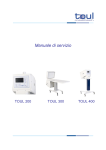
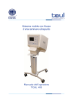
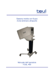
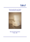
Download Service Manual TOUL 400 TOUL 200
Transcript
Service Manual TOUL 400 TOUL 200 Toul ® is registered by TOUL Meditech AB TOUL 200 and TOUL 400 bears the marking and comply with the provisions of the Medical Device Directive 93/42 EEC. Toul Meditech AB takes no responsibility for use of the product other than for those uses specified herein and disclaims any liability resulting from other uses. Observe all warnings and cautions. This manual covers software version 1.06 Toul 400/200 Type A2 Manual, revision 3.01 February 2013 Toul Meditech AB Copyright Toul Meditech AB 2012. All rights reserved. Unauthorized use, copying, or distribution of this manual is prohibited without the written permission from Toul Meditech AB. Content TOUL 200 .................................................................................................................................. 5 1. Installation instruction for TOUL 200 ................................................................................. 5 OndaSpace Pendant .......................................................................................................................... 5 Electrical installation ........................................................................................................................ 5 Mounting TOUL 200 ........................................................................................................................ 5 TOUL 400/200 ........................................................................................................................... 8 2. Recommended Maintenance ................................................................................................. 8 Ensuring Safety ................................................................................................................................. 8 Service indicators .............................................................................................................................. 8 HEPA Filter ....................................................................................................................................... 8 Yearly Maintenance .......................................................................................................................... 9 3. Replacing HEPA Filter ....................................................................................................... 11 4. Service Mode........................................................................................................................ 13 USB connector ................................................................................................................................. 13 Installation of driver ....................................................................................................................... 13 Setting up the connection ............................................................................................................... 13 Activating the service mode ........................................................................................................... 16 Resetting the counter ...................................................................................................................... 16 Service Commands.......................................................................................................................... 17 Exiting from service mode .............................................................................................................. 17 5. Contaminated unit ............................................................................................................... 18 6. Parts overview ...................................................................................................................... 19 TOUL 200 ........................................................................................................................................ 19 TOUL 400 ........................................................................................................................................ 21 7. Electrical connections ......................................................................................................... 23 8. Circuit boards and accessing parts ..................................................................................... 25 Connectors ....................................................................................................................................... 26 Power transformer .......................................................................................................................... 26 Replacing fuses ................................................................................................................................ 27 Removing the fan ............................................................................................................................ 27 9. Possible problems ................................................................................................................ 28 Bar code reader ............................................................................................................................... 28 Pillar of TOUL 400 ......................................................................................................................... 29 Sterile shield holders ....................................................................................................................... 30 Service manual TOUL 200/400 3 Trouble Shooting List ..................................................................................................................... 35 10. EMC declaration of TOUL 400/200 ................................................................................. 37 11. Manufacturer..................................................................................................................... 41 How to get in contact with Toul Meditech AB ............................................................................. 41 Service manual TOUL 200/400 4 TOUL 200/400 TOUL 200 1. Installation instruction for TOUL 200 The following installation instructions regarding mounting the unit and pendant arm into the ceiling only apply to TOUL 200. OndaSpace Pendant The pendant that supports TOUL 200 is manufactured by Ondal GmbH. Upon delivery TOUL 200 is accompanied by a separate instruction for the OndaSpace pendant. Refer to this instruction before you start mounting the pendant and select the appropriate mounting option that corresponds to the requirements and the construction of the ceiling. Electrical installation Electrical installation is required and the ceiling space, where the pendant arm shall be mounted, must be prepared with electrical wiring and a socket. The electrical installation shall be connected to a single fuse and a main power switch needs to be mounted on the wall. All electrical installation steps must be carried out by a certified electrician. Consult the maintenance department at the Hospital (or your workplace) since they most likely have qualified staff, or can give advice who to contact. Warning - When mounting the OndaSpace pendant it is necessary to be at least two persons. The device is heavy and it requires extra hands to hold some items while mounting the pendant. Mounting TOUL 200 For mounting the TOUL 200 and the pendant arm follow the steps below and see the illustration on the next page. 1. Measure all parts and adjust the lengths of the fixating items. It might be necessary with some slight adjustments. 2. Start by mounting the ceiling set (A) into the ceiling. Connect the earth wire to the earth pin on the ceiling plate (to be connected by a certified electrician). 3. Mount the flange tube (B) on the ceiling plate. The flange tube (B) can be sawed into the correct length. Service manual TOUL 200/400 5 TOUL 200/400 4. Mount the pendant arm on the flange tube and place the plastic cover over the ceiling plate (A). 5. Pull the cable through the pendant arm and leave some extra cable length in the upper connection. 6. Place the TOUL 200 unit on a table or a support stand. If possible use a stand or a table that can be lowered and raised since this will facilitate the mounting. A = Ceiling plate and plastic cover B = Flange tube C = Locking button D = Suspension adjustment screw E = 4 x MC6S M8x25 bolts 7. Pull out the locking button (C) and simultaneously push down the pendant arm by force. This step can be DANGEROUS and it requires TWO PEOPLE. Shift the arm towards the TOUL 200 unit and connect the pendant cable and plug into the corresponding connector on the TOUL 200 unit. 8. Arrange the surplus cable length inside the arm and make sure it will not be squeezed. 9. Push down the final bit on the pendant arm so it connects in its tube seating on the TOUL 200 unit. Fixate the connection by tightening the 4 x M8 bolts (E). Service manual TOUL 200/400 6 TOUL 200/400 10. The suspension of the arm can be adjusted with the suspension adjustment screw using a hex-key (D). Try to find the proper balance and adjust the screw so that the arm is correctly balanced. The arm shall stay in position holding up the sterile shield and at the same time being able to move freely up and down. Also refer to the OndaSpace instruction. 11. Start the TOUL 200 unit. Refer to the TOUL 200 Operator’s manual. - Adjusting the suspension might be necessary to repeat once in a while. The suspension shall be checked on the yearly procedure. Note Service manual TOUL 200/400 7 TOUL 200/400 TOUL 400/200 2. Recommended Maintenance Ensuring Safety To ensure safety and to keep your equipment in good working order it is necessary to carry out recommended maintenance and inspections. A qualified service technician should carry out technical maintenance and inspection. Contact your local distributor for information on whom you can consult for the yearly service of your unit, or contact Toul Meditech AB directly if you do not have access to a qualified service technician in your hospital. Address and phone numbers are listed at the end of this manual. Service indicators When the unit needs to be serviced a warning lamp will show up on the control panel as follows: Symbol Lamp Meaning Scheduled service will be needed within 50 operational hours. Start planning for service. The HEPA filter shall be replaced. Service is required immediately. A technical problem has occurred or the scheduled service is due. - Do not modify Toul 400/200 without authorization of the manufacturer. Warning HEPA Filter The filter needs to be replaced if any of the following conditions applies: • Yearly Maintenance procedure is due • The filter has been contaminated • The service symbol on the control panel is lit • The efficiency of the filter is suspected to be low • The fan has a strange noise Service manual TOUL 200/400 8 TOUL 200/400 Yearly Maintenance Once a year, or more frequently if necessary, you should replace the filter and perform an inspection to make sure all functions and control indicators work satisfactorily. It is also necessary to reset the counter for operational hours and to carry out a leakage test in order ensure accurate performance. Also carry out this procedure if the service indicator is lit indicating need for service. Follow these steps for yearly maintenance. 1. Turn off the unit and disconnect the power. 2. Replace the filter as described under “Replacing HEPA filter”, see next section. 3. Clean the cover and inner fan box with alcohol based detergent. 4. Put everything back correctly, according to the instructions under “Replacing HEPA filter”. 5. Connect the power. Start the unit and check that all buttons and controls function properly. Follow the instructions given under “Functional test” in the “General” section in the Operators manual. 6. Perform a safety and leakage test using a safety tester. Set up the program according to Class I and B. Record the measurements on a protocol and save it, so comparisons can be made with future tests. 1 USB connector 2 RCA video connector - Do not connect earth or the safety tester to the RCA video connector, since this could damage the unit. Caution Service manual TOUL 200/400 9 TOUL 200/400 7. With the fan turned on, use a flow meter and measure the airflow in the direction of the airflow up to 1.2 meter from the sterile shield. The air that comes out from the sterile shield should have a constant speed of 0.4 - 0.5 meter per second. If the air speed is not within this range contact Toul Meditech for assistance. 8. On TOUL 400 - check that the lock levers on the castors function properly by locking and releasing them. When in the released position check that all the castors can rotate freely. If a castor is defective it has to be replaced. Also visually check that there are no cracks, dents or other signs of damage on any of the castors. 9. On TOUL 200 - check that the pendant arm is correctly balanced, can move freely and stays in position. If the suspension of the arm needs to be adjusted refer to installation instruction of TOUL 200 Warning - Be sure to put back all parts in the correct order after finishing service and inspection. The filter may not be fitted incorrectly. Check especially that there are no remaining items, outside or inside the unit. Service manual TOUL 200/400 10 TOUL 200/400 3. Replacing HEPA Filter 1. Turn off the unit and disconnect the power. 2. Remove the sterile shield and dispose of it. Service manual TOUL 200/400 11 3. Untighten the bolts on the small filter brackets that fixate the HEPA filter. 4. Do not remove the brackets. Let them hang loose pointing down, as shown in the picture. TOUL 200/400 5. Remove the HEPA filter carefully by pulling out both sides simultaneously. Don’t use any tools to remove the filter. 6. Wipe the inside of the hood with alcohol. 7. Mount a new filter with the rubber gasket facing towards hood. Dispose of the old filter according to your local waste management regulations. 8. Put back the brackets that holds the filter and tighten the bolts. 9. The operational counter has to be reset after replacing the filter. Refer to “Resetting the counter” in the “Service Mode” section. Service manual TOUL 200/400 12 TOUL 200/400 4. Service Mode USB connector To start the service mode you first need to connect a PC at the USB-port (1). 1 USB connector 2 RCA video connector 1. Connect the USB cable from the PC into the USB socket. TOUL 400 and TOUL 200 have converters for USB to RS-232 which emulates a COM port. For installation of a suitable driver see “Install driver” in the next section. The RCA video connector can be used for Video to connect a slave monitor. Installation of driver To communicate with the unit you need to have the correct driver installed. The driver is supplied separately on a USB stick or it can be emailed upon request if you contact Toul Meditech. Setting up the connection 1. Start the TOUL unit. 2. Start Windows. 3. Connect a USB cable between the PC and the TOUL unit (see picture above). Service manual TOUL 200/400 13 TOUL 200/400 Click on START Click on HyperTerminal Select 5 small letters Click OK Select the highest port Service manual TOUL 200/400 14 TOUL 200/400 Click OK value 115200 value 8 value None value 1 value None Click OK Wait for 5 seconds for the text ” RTC_DateAndTime_Get: 07-06-29 13:22:35” to be displayed on the screen. Date and time on the TOUL unit shall be the same as on your PC. If this is not the case you can set date/time from the service mode, see “Service commands. The PC is now connected to the TOUL unit and will receive data from the unit continuously. To activate the service mode see below. Note - If the driver doesn’t work properly it may be a compatibility problem with your PC or operating system. The driver should work properly with XP and Windows 7. Service manual TOUL 200/400 15 TOUL 200/400 Activating the service mode Start the service mode by pressing the two middle buttons, and keep them pressed down for at least 3 seconds. > 3 sec (TOUL 400 above - the same blank buttons are used on TOUL 200) - After 3 seconds, the two buttons must be released at the same time. If the buttons are released before that time the system will go into standby mode. Note - The Toul unit cannot be started when you are in the service mode. The following text will appear in the Hyper terminal: Resetting the counter The unit has a built-in counter in the controller module for keeping track of operational hours. When the pre-set value of 1950 hours is reached the Service indicator will become yellow indicating need for service. After 50 more hours the indicator will alert in red. The counter needs to be reset manually after the filter has been replaced. 1. Press f in the Service mode to clear and reset the operational counter to zero. Service manual TOUL 200/400 16 TOUL 200/400 Service Commands There are several service commands that can be used for controlling the TOUL unit. They are accessed from the keyboard on the PC when it is connected to the unit. The commands are listed in the Hyper terminal. Below is a detailed explanation for each command. Command Meaning b Beep on f Reset operational counter n Beep off r Log file s Change date and time t Operational time High fan speed Medium fan speed Low fan speed h m l Warning Function Press b to activate a beep sound each time the bar code reader reads a new Sterile shield. Press f to clear and reset the operational counter to zero. This should be done each time the HEPA filter is replaced. Press n to turn off the beep sound each time the bar code reader reads a new Sterile shield. Press r for showing the log file of the unit. When this function is executed a large amount of data will show up in the Hyper terminal, if the unit has been used for a long time. If you want to save log data you can copy the text and paste it into a word document. Enter time and date in the format yymmddhhmmss and press s for setting the system clock with the new time and date. Enter all characters in a sequence without any blanks. For instance; 14January 2013 3 pm is: 130114150000. Press t for showing the unit’s operational hours. Press h to set the fan speed to high. Press m to set the fan speed to medium. Factory setting. Don not use this setting. l sets the fan speed to low. - Changing the fan speed alters the performance of the unit and the air flow capacity. Do not change the fan speed to low. Normal fan speed should be set to Medium. Exiting from service mode The unit cannot be operated as normal while you are in Service mode. 1. Exit the service mode by pressing the space bar or the enter key. Service manual TOUL 200/400 17 TOUL 200/400 5. Contaminated unit If the unit has been contaminated during a procedure, or if spilled fluid has entered the unit, you must take special precautions. Always wear rubber gloves when such cleaning should be performed. The Operator’s manual contains information on how the unit should be decontaminated. For internal cleaning follow the cleaning instructions below: 1. Turn off the unit disconnect the power. 2. Remove the single-use sterile shield and dispose of it according to your local routines for managing infectious refuse. 3. Remove the filter according to previous instructions. 4. Moisten a soft cloth with a cleaning solution of low level disinfectant such as isopropyl alcohol or similar, and wipe all accessible inner and outer surfaces gently. Clean the inside of the fan box with alcohol based detergent. The frame where the filter gasket is fitted must be thoroughly cleaned with alcohol. 5. Remove any debris or dirt. 6. If liquids have entered the unit, leave the unit to dry for at least 24 hours. It should be disassembled and turned off, and be placed in room temperature. 7. Inspect all connectors, inlets and openings and make sure that no stains, soil or dust is present. 8. Inspect the filter thoroughly before you put it back. If the filter has been soiled/spilled on it should be replaced with a new one. 9. Assemble the unit according to earlier instructions and make sure put everything back correctly. 10. Attach a new sterile shield. 11. Plug the unit in and turn it on. Leave the unit running for at least 30 minutes. 12. Turn the unit off and remove the sterile shield and dispose of it according to your local routines for managing infectious refuse. Service manual TOUL 200/400 18 TOUL 400/200 6. Parts overview TOUL 200 No 1 2 3 4 5 6 7 8 9 10 11 12 13 14 15 Amount 1 1 1 1 1 1 1 1 2 1 1 1 1 1 1 Item number 300178-3-0026 TM ECM 300178-3-0008 300178-3-0009 300178-3-0014 D2E146HS9721 300178-3-0119 HEPA-T200/400-01 300178-3-0012 300178-1-032 300178-3-0018 300178-3-0015 EA1050F-120 300178-3-0112 300144-3-0018 Service manual TOUL 200/400 Description Hood T200 TM ECM Manoeuvre panel Fan Distance ring Fan Plate Fan Upper sterile shield holder HEPA filter absolute Air inlet grid Transformer Lower sterile shield holder Camera front glass AC/DC converter Control panel T200/T400 Camera/IR smst 19 TOUL 400/200 16 17 18 19 20 21 22 23 1 1 2 1 4 2 1 1 300178-3-0020 KD14.1101.151 AA-01066-MD Rev G p AA-01066-MD Rev Gh 300178-3-0022 Cable tie foot Nut protector, M8 40-290-88 24 25 26 27 28 1 1 1 1 1 300178-3-0078-3 300178-3-0077-2 NVL-1001-RS232C 300178-3-0079-0 300178-3-0115 Service manual TOUL 200/400 Ceiling attachment IEC Appliance Connector Gasket Trafo holder Attachment plate filter T200/400 Cable tie foot Nut protector, M8 Single pole safety connector SEB 2610 F4,8 Scanner mounting plate Scanner adjustment plate Scanner Cover glass for bar code reader Overlay Toul 200 20 TOUL 400/200 TOUL 400 Parts No 1 2 3 4 Amount 1 1 1 1 Item number 300178-3-0025 TM ECM 300178-3-0008 300178-3-0009 Service manual TOUL 200/400 Description Hood T400 TM ECM Manoeuvre panel Fan distance ring 21 TOUL 400/200 5 6 7 8 9 10 11 12 13 14 15 16 17 18 19 20 21 22 23 24 25 26 1 1 1 1 2 1 1 1 1 27 1 28 29 30 31 32 33 34 35 36 37 1 1 1 1 4 1 1 1 1 1 300178-3-0014 D2E146HS9721 300178-3-0019 HEPA-T200/400-01 300178-3-0012 300178-1-011 300178-3-0018 300178-3-0015 300178-3-0016 EA1050F-120 300178-3-0018 300178-3-0112 300144-3-0018 300178-3-0023 AA-01066-MD Rev G p AA-01066-MD Rev Gh 932 325-100 KD14.1101.151 Cable tie foot 12-T11539 Nut protector, M8 2 x 007700166 2 x 00770382 Transformer 1.58.000.013.30 1.43.000.160.30 Leveller, pole 300178-3-0039 300178-3-0047 300178-3-0022 NVL-1001-RS232C 300178-3-0036 300178-3-0038 300178-3-0040 40-290-88 38 39 40 1 1 1 300178-3-0078-3 300178-3-0077-2 300178-3-0079 1 1 1 1 2 1 1 1 2 1 3 2+2 Service manual TOUL 200/400 Fan Plate Fan Upper sterile shield holder HEPA filter absolute Air inlet grid Transformer Lower sterile shield holder Camera front Glass Shaft AC/DC converter Midpart distance T400 Control panel T200/T400 Camera/IR smst Midpart topdisk Gasket Trafo holder CA 6 GD socket IEC Appliance Connector Cable tie foot Telescopic frame Nut protector, M8 Wheels with brake Wheels without breaks Transformer 1.58.000.013 – PHOENIX MECANO Leveller, engine Leveller, pole Top sheet Foot Attachment plate filter T200/400 Scanner Top bracket Top bracket Bearing plate T400 Single pole safety connector SEB 2610-F4,8 Scanner mounting plate Scanner adjustment plate Cover glass for barcode reader 22 TOUL 400/200 7. Electrical connections No 1 2 3 4 5 6 7 8 9 Service manual TOUL 200/400 Description FAS board, phase board for distance sensor SCM board, flow sensor board TCM board, main control board ECM board, USB output Distance sensor Camera Air flow sensor Bar code reader Monitor module 23 TOUL 400/200 10 11 12 13 14 15 Service manual TOUL 200/400 BTN board, relay control, buttons PWR board, relay module Power supply 12 V Isolation transformer Fan Raise/lowering control unit 24 V supply TOUL 400 only) 24 TOUL 400/200 8. Circuit boards and accessing parts This section describes the circuit boards and specific parts and how to access them in a safe and proper way. The circuit boards are situated behind the control panel. Remove the 10 screws around the control panel and gently fold down the control panel. Disconnect all connectors and remove the circuit boards completely. Service manual TOUL 200/400 25 TOUL 400/200 Connectors 1 2 3 4 5 6 7 8 9 10 Power supply – LCD display LCD display signal Signal from camera, distance sensor and airflow External USB / Video slave monitor Bar code reader Power supply to PCB Height adjustment TOUL 400 Power supply fan 230 V for fan and up/down (Toul 400 only) Earth cable Power transformer The power transformer is situated under the circuit boards/control panel. 1 2 Service manual TOUL 200/400 Power transformer Toroid 26 TOUL 400/200 Replacing fuses The 2 fuses are placed in the compartment just above the power switch. If the fuses need to be replaced follow these steps: 1. Disconnect power and open the lid of the compartment by unlocking the tab. 2. Replace the fuses with 3.15 A for 230 V or 5 A for 115 V. 3. Close the compartment lid. Fuse compartment TOUL 400 and TOUL 200 (TOUL 200 has no power inlet) Removing the fan The fan may need service if any of the following conditions apply. • The fan will not start • The fan seems to be stuck or does not run smoothly • The fan has a strange noise Follow these steps to remove the fan: 1. Remove the filter according to previous instructions on “Replacing HEPA filter” 2. Remove the screws holding the fan on the stainless steel plate. 3. Disconnect the fan connector and lift out the fan. 4. Perform necessary service on the fan or replace it if it cannot be repaired. 5. Connect and mount back the fan and filter in reverse order. Service manual TOUL 200/400 27 TOUL 400/200 9. Possible problems All TOUL units have built-in self-diagnostics for detection of faulty conditions. Detected problems, need of service or an internal equipment failure are presented on the control panel. Other specific problems that you may encounter are mentioned here: Bar code reader The bar code reader is situated at the bottom of the air hood and is directed towards the sterile shield bar code. The unit uses an algorithm to keep track on which sterile shield that is being used. If the same sterile shield is mounted twice the unit will not accept it and the fan cannot be started. Possible problems that may arise with the sterile shield is either that an old sterile shield is used or that the time limit has expired for how long the fan or the unit can be turned off. Keep in mind the following time limits: • • • The unit can be in standby mode for as long as needed with a new sterile shield registered before the fan is started. The fan can be turned off for 30 minutes with the same sterile shield mounted. The unit can be powered off for 15 minutes with the same sterile shield mounted. If there are problems with recognising the bar code, the glass may be dirty or scratched. The bar code reader glass can be cleaned with isopropyl alcohol on a cotton applicator if it is dirty. If the glass is scratched it needs to be replaced unscrew the protective glass. Remove the glass and mount a new glass. Make sure that the glass fit tight against the hood, otherwise unfiltered air may be distributed. Service manual TOUL 200/400 28 TOUL 400/200 Bar code reader glass Connector on pillar of TOUL 400 Pillar of TOUL 400 The TOUL 400 unit has the pillar steering cable underneath the control panel. This cable must not be bent or destroyed in any way. Check that this cable has free passage and is a good condition if you come across problems lowering or raising the hood. To separate the pillar from the hood: 1. Disconnect the connector underneath the hood. Service manual TOUL 200/400 29 TOUL 400/200 2. Turn sideways plate. the hood from the 3. Unscrew the four bolts and carefully lift the hood. Sterile shield holders If the sterile shield holders become damaged or bent the sterile shield will not fit tightly and air leakage may appear. To replace the sterile shield holders follow these steps: 1. Disconnect the power. 2. Remove the HEPA filter, see previous instructions on removing the HEPA filter. 3. Remove the old sterile holders by pulling them off. Make sure all adhesive comes off. 4. Clean the upper/lower surfaces thoroughly with alcohol based detergent. NOTE: Make sure to clean thoroughly in order for the adhesives on the new sterile shield plastic holders to stick properly to the surface. If the surfaces aren’t clean the holders risk becoming loose. Also, make sure the surfaces are dry before mounting the holders. Service manual TOUL 200/400 30 TOUL 400/200 5. Do this step to assure where to place the lower sterile shield holder. Without removing the seal of adhesive tape, try out the position of the lower sterile shield holder by placing the front end (where the adhesive sits) precisely behind the small elevation, as indicated by the arrow. Pull forward towards the elevation. It should fit perfectly. (Once you remove the seal the adhesive will stick and the position will be fixed). 6. Remove the seal from the adhesive tape from the new lower sterile shield holder. Service manual TOUL 200/400 31 TOUL 400/200 7. Now, place the sterile shield holder with the adhesive tape side pointing down and place the front end precisely behind the small elevation, as indicated by the arrow, and as you did in step 5. Pull forward towards the elevation. NOTE: Make sure that the front of the adhesive is in contact with the elevation on the hood. See arrow on the picture. 8. Push down with pressure until it sticks. 9. Sweep your fingers across the holder with pressure, making sure the holder sticks. Service manual TOUL 200/400 32 TOUL 400/200 10. Follow this step to assure where to place the upper sterile shield holder. Without removing the seal of the adhesive tape, try out the position of the upper sterile shield holder. Move it forwards until it comes into contact with the small elevation in the front of the hood. Keep the back of the sterile shield holder tilted so it doesn’t come into contact with the inner hood surface. 11. Once in position, and in contact with the small elevation, flip the rear end upwards, so it comes into contact with the inner hood surface. 12. Remove the seal of the adhesive tape from the upper sterile shield holder. 13. Repeat the previous steps but with the seal removed and adhesive tape pointing up. Push it towards the small elevation in the hood. Service manual TOUL 200/400 33 TOUL 400/200 NOTE: As for the lower holder make sure that the front of the sterile shield holder comes into contact with the elevation on the inside on the hood. The red arrow points out the small elevation where the front end of the sterile shield holder needs to come into close contact with. NOTE: This view shows the small elevation and sterile shield holder front, from underneath of the inside the hood. 14. Sweep your fingers across the holder with pressure, making sure the holder sticks. 15. Check that the sterile shield holders are mounted correctly by inserting an old sterile shield cardboard strip in the holders. Pull the paper strip in both directions through the plastic holders. It shall run smoothly, but with some resistance without getting stuck. If the resistance is too big, insert your fingers between the plastic sterile holder and bend carefully to widen the gap. 16. Check the lower sterile shield holder in the same manner as the upper. 17. Put back the HEPA filter. Service manual TOUL 200/400 34 TOUL 400/200 Trouble Shooting List The table below lists possible problems and gives general advice on what actions to take when problems are met. Always contact Toul Meditech AB for advice if you come across problems that cannot be solved. Problem The unit does not start Possible Cause Remedy The power cable has been disconnected Check that the cable is plugged in at the wall outlet and the unit properly Rear cables disconnected/broken Check the rear cables Power transformer not connected/working Check the power transformer and the connections located underneath the control panel A fuse has blown The fuses are located near the power switch. For 230 V replace with fuse: 3.15 A slow, 5 x 20 mm None of the above The fan does not start For 115 V replace with fuse: 5A Contact Toul Meditech AB or your distributor The sterile shield has Make sure to use a new sterile not been replaced shield for every procedure The fan has been If the 30 minute's interval is turned off longer than exceeded a new sterile shield 30 minutes must be mounted Service manual TOUL 200/400 The unit needs service Check if the unit is due for service (after 2000 hours) Power is disconnected to the fan Check that the fan gets power. Remove the filter and fan. Disconnect the fan cable and measure the power between the grey and blue line. It shall be 230 or 115 V. If the fan seems to be faulty replace it for a new one. 35 TOUL 400/200 Other Try to restart the unit Contact Toul Meditech AB or your distributor The fan has strange The yearly service noise interval is due Other Check the service interval and if necessary carry out service according to instructions in this manual Replace the fan Contact Toul Meditech AB or your distributor No picture from the Loose connection camera Check the connectors at the controller module and monitor module plate Contact Toul Meditech AB or your distributor Cannot raise/lower Loose connection the hood (TOUL 400) Broken cable Check that the cables at the power transformer are connected. Check the cable at the control panel. None of the above Contact Toul Meditech AB or your distributor The red service indicator is lit Due for yearly maintenance Check the service interval and perform service if necessary No response from control panel A connector is loose Check the connectors on the controller module. The control panel is broken Replace the entire control panel The sterile shield is mounted incorrectly Check that the sterile shield has the bar code towards the reader. Cannot read/recognise the sterile shield Bar code reader is not Check that the bar code reader working gives out a red light when the “Sterile” button is pressed. The bar code reader is dirty Service manual TOUL 200/400 36 Clean the bar code reader with isopropyl alcohol on a cotton applicator. TOUL 400/200 10. EMC declaration of TOUL 400/200 Guidance and manufacturer’s declaration – electromagnetic emissions The Toul 400/200 system is intended for use in the electromagnetic environment specified below. The customer or the user of the Toul 400/200 system should assure that it is used in such an environment. Emissions test Compliance RF emissions CISPR 11 Group 1 RF emissions CISPR 11 Class B Harmonic emissions IEC 61000-3-2 Not applicable Voltage fluctuations/ flicker emissions IEC 61000-3-3 Not applicable Electromagnetic environment – guidance The TOUL 400/200 uses RF energy only for its internal function. Therefore, its RF emissions are very low and are not likely to cause any interference in nearby electronic equipment. The TOUL 400/200 System is suitable for use in all establishments other than domestic and those directly connected to the public low-voltage power supply network that supplies buildings used for domestic purposes. 37 TOUL 400/200 Guidance and manufacturer’s declaration – electromagnetic immunity The TOUL 400/200 System is intended for use in the electromagnetic environment specified below. The customer or the user of the TOUL 400/200 System should assure that it is used in such an environment. Immunity test IEC 60601 test level Compliance level Electromagnetic environment – guidance Electrostatic discharge (ESD) IEC 61000-4-2 ±6 kV contact ±6 kV contact ±8 kV air ±8 kV air Electrical fast transient/burst IEC 61000-4-4 ±2 kV for power supply lines ±2 kV for power supply lines The customer PC used for the system provides TOUL 400/200 Amplifier with power. The PC itself is not part of this declaration. The mains power quality used for the PC should be that of a typical commercial or hospital environment. Surge IEC 61000-4-5 ±1 kV line(s) to line(s) ±1 kV line(s) to line(s) ±2 kV line(s) to earth ±2 kV line(s) to earth Mains power quality should be that of a typical commercial or hospital environment. Voltage dips, short interruptions and voltage variations on power supply input lines IEC 61000-4-11 <5 % U T (>95 % dip in U T ) for 0,5 cycle 40 % U T (60 % dip in U T ) for 5 cycles 70 % U T (30 % dip in U T ) for 25 cycles <5 % U T (>95 % dip in U T ) for 5 sec <5 % U T (>95 % dip in U T ) for 0,5 cycle 40 % U T (60 % dip in U T ) for 5 cycles 70 % U T (30 % dip in U T ) for 25 cycles <5 % U T (>95 % dip in U T ) for 5 sec Mains power quality should be that of a typical commercial or hospital environment. If the user of the TOUL 400/200 System requires continued operation during power mains interruptions, it is recommended that the TOUL 400/200 System be powered from an uninterruptible power supply or a battery. Power frequency (50/60 Hz) magnetic field IEC 61000-4-8 3 A/m 1000 /m Power frequency magnetic fields should be at levels characteristic of a typical location in a typical commercial or hospital environment. NOTE ±1 kV for input/output lines Floors should be wood, concrete or ceramic tile. If floors are covered with synthetic material, the relative humidity should be at least 30 %. U T is the a.c. mains voltage prior to application of the test level. 38 TOUL 400/200 Guidance and manufacturer’s declaration – electromagnetic immunity The TOUL 400/200 System is intended for use in the electromagnetic environment specified below. The customer or the user of the TOUL 400/200 System should assure that it is used in such an environment. Immunity test IEC 60601 test level Complianc e level Electromagnetic environment – guidance Portable and mobile RF communications equipment should be used no closer to any part of the TOUL 400/200 System, including cables, than the recommended separation distance calculated from the equation applicable to the frequency of the transmitter. Recommended separation distance Conducted RF IEC 61000-4-6 3 Vrms 150 kHz to 80 MHz 10 Vrms Radiated RF IEC 61000-4-3 3 V/m 80 MHz to 2,5 GHz 15 V/m d = 0,4 P d = 0,3 P 80 MHz to 800 MHz d = 0,5 P 800 MHz to 2,5 GHz where P is the maximum output power rating of the transmitter in watts (W) according to the transmitter manufacturer and d is the recommended separation distance in metres (m). Field strengths from fixed RF transmitters, as determined by an a electromagnetic site survey, should be less than the compliance level in each b frequency range. Interference may occur in the vicinity of equipment marked with the following symbol: NOTE 1 At 80 MHz and 800 MHz, the higher frequency range applies. NOTE 2 These guidelines may not apply in all situations. Electromagnetic propagation is affected by absorption and reflection from structures, objects and people. a b Field strengths from fixed transmitters, such as base stations for radio (cellular/cordless) telephones and land mobile radios, amateur radio, AM and FM radio broadcast and TV broadcast cannot be predicted theoretically with accuracy. To assess the electromagnetic environment due to fixed RF transmitters, an electromagnetic site survey should be considered. If the measured field strength in the location in which the [ EQUIPMENT or SYSTEM ] is used exceeds the applicable RF compliance level above, the [ EQUIPMENT or SYSTEM ] should be observed to verify normal operation. If abnormal performance is observed, additional measures may be necessary, such as re-orienting or relocating the TOUL 400/200 System. Over the frequency range 150 kHz to 80 MHz, field strengths should be less than 10 V/m. 39 TOUL 400/200 Recommended separation distances between portable and mobile RF communications equipment and the TOUL 400/200 System The TOUL 400/200 System is intended for use in an electromagnetic environment in which radiated RF disturbances are controlled. The customer or the user of the TOUL 400/200 System can help prevent electromagnetic interference by maintaining a minimum distance between portable and mobile RF communications equipment (transmitters) and the TOUL 400/200 System as recommended below, according to the maximum output power of the communications equipment. Rated maximum output power of transmitter Separation distance according to frequency of transmitter m 150 kHz to 80 MHz 80 MHz to 800 MHz 800 MHz to 2,5 GHz d = 0,4 P d = 0,3 P d = 0,5 P 0,01 0,04 0,03 0,05 0,1 0,13 0,09 0,16 1 0,4 0,3 0,5 10 1,3 0,9 1,6 100 4,0 3,0 5,0 W For transmitters rated at a maximum output power not listed above, the recommended separation distance d in metres (m) can be estimated using the equation applicable to the frequency of the transmitter, where P is the maximum output power rating of the transmitter in watts (W) according to the transmitter manufacturer. NOTE 1 At 80 MHz and 800 MHz, the separation distance for the higher frequency range applies. NOTE 2 These guidelines may not apply in all situations. Electromagnetic propagation is affected by absorption and reflection from structures, objects and people. 40 TOUL 400/200 11. Manufacturer How to get in contact with Toul Meditech AB Toul Meditech AB Tunbytorpsgatan 31 721 37 Västerås Phone: int + 46 21 13 50 00 Fax: int + 46 21 13 86 45 Internet: www.toulmeditech.com E-mail: [email protected] Your distributor: TOUL 400/200 TOUL 400/200 TOUL 400/200 Toul Meditech AB Tunbytorpsgatan 31 SE-721 37 Västerås Sweden


