1
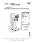
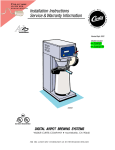
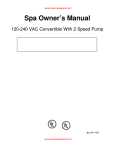
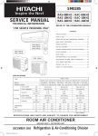
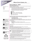
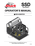
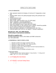
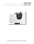
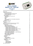
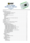
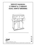
Rev. 8/16/00 Wilbur Curtis Co., Inc. ALPHA DIGITAL COFFEE BREWERS SERVICE MANUAL Included in this service manual is information on the Alpha 1D, Alpha 2D, Alpha 3D, Alpha 3DL, Alpha 3DR, Alpha 5DL, Alpha 5DR and Alpha 6D. The information is common to all Alpha digital brewers except where noted. INCLUDES THE FOLLOWING UNITS: – ALPHA 2D – ALPHA 1D – ALPHA 3DL – ALPHA 3DR – ALPHA 6D – ALPHA 5DL C – ALPHA 3D – ALPHA 5DR CONTENTS Alpha Digital . . . . . . . . . 1 Setup . . . . . . . . . . . . . . . . 1 Setup Steps . . . . . . . . . . 2 Brewing . . . . . . . . . . . . . 2 Coffee Requirements . 2 Programming . . . . . . . . . 3 Trouble Shooting . . . . . . 5 Replacing Membrane . 7 Care & Maintenance . 8 Illustrated Parts Lists 9 - 15 Wiring Diagrams Alpha 1D . . . . . . . . . 16 Alpha 2D . . . . . . . . . 17 Alpha 3D . . . . . . . . . 18 Alpha 3DR . . . . . . . . 19 Alpha 3DL . . . . . . . . 20 Alpha 5D . . . . . . . . . 21 Alpha 3D-61/63 . . . . 22 Alpha 6D . . . . . . . . . 23 Alpha 3D - Export . . 24 Back Cover Warranty . . . Carton Contents All products manufactured by the Part Nº Qty Item Wilbur Curtis Company are thoroughly 1 Automatic Coffee Brewer . . . . . . . . . inspected at the factory and are Alpha 1 Brewcone . . . . . . . . . . . . . . . . . . . . . . . WC-3621 warranted to be free of all defects and 25 faulty workmanship. The Alpha unit is Paper Filters . . . . . . . . . . . . . . . . . . . . . . CR-10 packaged for maximum protection for 1 Elbow Fitting, 3/8 X 1/4 Flare . . . . . . . . WC-2401 shipping. Make sure the shipping carton is not damaged or punctured. Unpack the carton carefully, inspecting the contents for any damage that may have occurred in transit. Report any damage immediately to the freight company. 9/6/00 12.2 f-2068 revA.p65.p1 ALPHA DIGITAL The Alpha Digital series of automatic coffee brewers require installation to be in compliance with all local water and electrical power codes. The Alpha is designed to brew 12 cups at a time. The Alpha 3D, 3DL and 3DR have three warmer plates that allow up to three decanters to be kept at serving temperature. The hot water faucet lets you draw hot water for tea, instant soups, chocolate drinks or cup meals - even during the brew cycle. z WARMER PLATES z ELECTRONIC CONTROL BOARD z z DUMP VALVE z HOT WATER FAUCET z z SPRAY HEAD z BREW CONE z HEATING TANK 12 CUP DECANTER (NOT INCLUDED) z WATER INLET VALVE WARMER PLATE z Figure 1. Alpha Brewing System, Basic Components. THIS EQUIPMENT IS TO BE INSTALLED TO COMPLY WITH THE APPLICABLE FEDERAL, STATE, OR LOCAL PLUMBING CODES HAVING JURISDICTION. CAUTION DO NOT connect this brewer to hot water. Inlet valve not rated for hot water. SETUP The Alpha unit should be located on a solid counter top. The counter top should be level. Connect the water line from the water filter to the unit using ¼" copper tubing with a flare fitting at the end. Some type of water strainer must be used to maintain a trouble-free operation. In areas with extremely hard water, we suggest that an Everpure QC7-MH water filter be installed. Water filters may be ordered from the Wilbur Curtis Company. For customer service call (800) 421-6150. The National Sanitation Foundation (NSF), requires the following water hookup: 1. A quick disconnect water connection or enough extra coiled tubing (at least 2x the depth of the unit) so that the machine can be moved for cleaning underneath. 2. An approved flow back prevention device, such as a double check valve to be installed between the machine and the water supply. Alpha decanter brewers are shipped with the power cord connected inside the machine. The power cord ends with an electric plug having two flat blades with a round grounding pin, 120VAC current and 20 amp rating. Some units are rated for 220 volts. Check the serial plate on the side of the machine to make sure of the electrical requirements for your unit. 1 Setup Steps 1. Connect a ¼" copper water line from your facility to the ¼" flare water inlet fitting on the valve, behind the machine. Water pressure going to the machine must be stable. Use a water regulator to maintain constant pressure. This brewer works perfectly when water pressures are from 20 to 90 psi. 2. Plug the power cord into an electrical outlet rated at 20A. 3. Turn on the toggle switch behind the unit. The heating tank will start to fill. When the water reaches the probe, the heating element will turn on automatically. 4. The heating tank will require 20 to 30 minutes to reach operating temperature (200ºF). The READY TO BREW indicator will light at this time. 5. When water reaches operating temperature, dispense about 12 ounces of hot water through the hot water faucet to lower the water level in the heating tank. You can also dispense only enough water to activate the liquid level control. BREWING STEPS FOR BREWING COFFEE: 1. Place a paper filter into the brew cone. Pour ground coffee into the filter. 2. Slide the brew cone into place. When pushed in against the stop, the brew cone fits into the slide rails and centers it under the sprayhead (see Figure 1. illustrating basic components). 3. Place a clean coffee decanter on the warmer plate. CAUTION - Always use an empty decanter before starting a brew cycle. 4. To start brewing, push in the momentary brew switch, located on the front panel. The brew cycle will take approximately three minutes to complete. To stop a brew cycle press the ON/OFF button. CAUTION - Wait for hot coffee to stop dripping from brew cone before lifting decanter. 5. To stop a brew cycle press the ON/OFF button. COFFEE REQUIREMENTS The Alpha coffee brewer will produce excellent results using most grades of coffee available from your coffee distributor. Coffee suppliers can provide coffee in convenient pre-measured envelopes. The Alpha coffee brewer is designed for ground coffee; Freeze Dried or Liquid coffee products will not work. The Wilbur Curtis Company manufactures bulk coffee dispensers (Models MCD-7 or MCD-7G) that consistently dispense ground coffee in selected amounts. Figure 2. MCD-7 Coffee Dispenser 2 PROGRAMMING (ONLY REQUIRED IF FACTORY SETTINGS MUST BE CHANGED) IMPORTANT These digital brewers are thoroughly tested and programmed at the time of manufacture. A few brew cycles may be required for unit to normalize. ENTERING THE PROGRAM MODE For all programming functions you must first enter the programming mode as follows: z Turn OFF the power from the Control Panel by pressing z Press and HOLD BREW and press and RELEASE MODE #1 z Continue HOLDING BREW until MODE #2 z Continue HOLDING BREW until MODE #3 z Continue HOLDING BREW until ON/OFF ON/OFF . . starts blinking; RELEASE. READY TO BREW stops blinking; RELEASE. READY TO BREW READY TO BREW stops blinking and remains on; RELEASE. (Over) CONFIRM/RESET BREW TEMPERATURE ENTER THE PROGRAMMING MODE #1: (PRE-PROGRAMMED FOR 200º F) z Press BREW for two seconds, then RELEASE. z will start blinking. Each blink equals 2º F, starting at 170º (max. temp. 204º F or 18 blinks). READY TO BREW z To change Temperature, press and HOLD BREW . z will start QUICK flashing. Each QUICK flash equals 2º F. After reaching 204º, temperature starts over at 170º. READY TO BREW z RELEASE BREW when the desired temperature is reached. The newly set temperature will now be displayed. To set and exit, press ON/OFF . 3 CHANGE BREW VOLUME IMPORTANT - Before changing the brew volume, place a measuring container on the brew deck and insert the brew cone. ENTER THE PROGRAMMING MODE #1: (PRE-PROGRAMMED FOR APPROXIMATELY 64 OUNCES) z Press and HOLD BREW until hot water starts running, then RELEASE. z When desired volume is reached, press BREW again to stop the flow. z To set and exit, press ON/OFF . TO ACCESS PREVENTATIVE MAINTENANCE BREW CYCLE COUNTER ENTER THE PROGRAMMING MODE #2: z will now start a pattern of LONG and SHORT blinks. This pattern identifies the number of brew cycles. SHORT blinks indicate the brew number from 1 to 9. LONG blinks separate 1's, 10's, 1,000's and 10,000's. READY TO BREW WARMER QUALITY TIMER - Factory Preset to OFF TO DETERMINE WARMER SETTING AND CHANGE TIME z Warmer must be ON. Press and HOLD WARMER until light goes OFF, RELEASE. z The light will start blinking. Count the blinks. Each blink=5 minutes (maximum 50 minutes). z At the end of the cycle, press and hold WARMER until the light begins quick flashing. The cycle will start over after 11 flashes (a setting of 11 flashes is the OFF position). z When the desired time is reached, RELEASE WARMER . z To set and exit, press ON/OFF . Table 1. Te mperature Settings NUMBER NUMBER OF BLINKS TEMPERA- OF BLINKS TEMPERA10 1 TURE TURE 11 2 188º F 170º F 12 3 190º F 172º F 13 4 192º F 174º F 14 5 194º F 176º F 15 6 196º F 178º F 16 7 198º F 180º F 17 8 200º F 182º F 18 9 202º F 184º F 204º F 186º F Table 2. Exa mple of Brew Counting Code SETS BLINKING LIGHT PATTERN 1ST 2ND 3RD 4TH 5TH END 4 x 1= 2 x 10 = 0 x 100 = 1 x 1,000 = 0 x 10,000 = TOTAL BREWS 4 NUMBER OF BREWS 4 20 0 1,000 0 01024 TROUBLE SHOOTING ERROR CODES: All Alpha Digital brewers contain various safety features in the electronic circuitry that shut down the functions of the unit in the event of a system failure. Error codes are signalled by the BREW READY light blinking. Deciphering the code: WATER LEVEL PROBLEM 3 LONG AND 1 SHORT TEMPERATURE SENSOR PROBLEM 3 LONG AND 2 SHORT ANY SERVICE DONE ON THIS UNIT MUST BE PERFORMED BY A QUALIFIED SERVICE TECHNICIAN. PROBLEM: WATER DOES NOT FLOW INTO HEATING TANK POSSIBLE CAUSE CODE: SOLUTION 1 . Water line turned off or water filter needs changing Make sure the unit is receiving enough water pressure. Open the water line. Change the filter or filter element. 2 . Water inlet valve coil burned out Turn the brewer off. Disconnect wires from water inlet coil terminals and connect a power cord to the terminals. Plug cord into a 120V outlet and verify if water flows when plugged in and stops when power is disconnected. If valve fails this test, replace valve. 3. Grounded probe When the water level gets below the probe tip, water should automatically refill the tank. If not, pull wire off the probe terminal. Water should now start flowing into the tank. If not, check the control board of the microprocessor assembly (see step 4), or inlet valve (step 5, below). 4 . Defective or burned out control board Pull wire out of probe terminal. With a voltmeter, check voltage at the water inlet coil terminals. This should read 110-120 volts. If no voltage is present, check control board. Make sure the control board is energized on terminals WHT & BLK. Lack of power to these terminals will indicate a defect within the circuit board. Replace the microprocessor assembly. Check for loose connections at terminals. PROBLEM: WATER IN HEATING TANK OVERFLOWING POSSIBLE CAUSE CODE: SOLUTION 5 . Defective water inlet valve Unplug the unit and observe water level. If water continues to flow into tank, clean or replace valve. 6 . Probe limed up Pull wire off from probe terminal. Touch the metal body of the heating tank with the end of this wire (to ground the wire). If water stops flowing, try cleaning the probe. Probe may have to be replaced. 7 . Non-grounded or loose terminal connections at control board The control board must be grounded. Check for loose connections at the terminals. Make sure the grounding wire is securely fastened to the chassis. 5 TROUBLE SHOOTING, CONTINUED PROBLEM: WATER IN TANK DOES NOT GET HOT OR WATER TEMPERATURE TOO LOW CODE: SOLUTION POSSIBLE CAUSE 8. Power is off Make sure unit is on; power cord plugged in. Toggle switch is on. Breaker is on. 9. Defective or loose heat sensor Remove the sensor and squeeze a dab of silicone compound (part no. WC-5229) between the sensor and the tank body. Make sure the fastening nut is secure. Check the wire for damage. 10. Burned out heating element Check element for continuity and or check with clamp ammeter. This should show a reading of approximately 15 amps (depending on element wattage). If no power is going through element, replace the heating element. 11. Defective control board If checks #8, #9 and #10 are normal, the control board is not operating correctly. Replace the microprocessor assembly (#8, figure 6.). PROBLEM: WATER NOT FLOWING FROM SPRAYHEAD CODE: SOLUTION POSSIBLE CAUSE 12. Sprayhead clogged Remove sprayhead and clean. Clean the sprayhead fitting. 13. Water level is too low in heating tank Check water level in tank. If water is not flowing into the tank, review steps 1 thru 4, previous page. 14. Defective control board Check the continuity between terminals WHT & BREW VLV. When the BREW button is pressed, there should be solid continuity between these two terminals. If not, replace the membrane control panel (see the instructions below). Make sure the board is receiving 110 to 120 volts at terminals BREW VLV and WHITE when BREW switch has been pressed. There should be 110 to 120V going to the dump valve. If not, then the control board is faulty. 15. Defective dump valve or coil If the control board is functioning properly (step 14), check the dump valve. Measure voltage across the two terminals of the valve coil. You should read 110 to 120 volts. Check also for clogging or lime deposits. Clean if possible. Replace valve or coil. REPLACING THE MEMBRANE CONTROL PANEL IMPORTANT - This procedure requires careful positioning of the membrane control panel. Improper application of the new part will ruin the membrane when you try to lift it again. You will have to acquire an additional panel to complete the task. TEST Before you actually remove the old membrane, test the old one by using your new membrane. Your old one may be okay. 6 1. Unplug the machine from your power source. 2. Remove the cover accessing the control board. 3. Unplug the ribbon connector from the control board then take the new membrane and plug the connector into the control board. Place it on a hard surface outside the unit. CAUTION Do not bend the new membrane. When pressing the buttons always have a hard, flat, surface to push against. The tiny dome switches within the membrane may become inverted unless you have something solid behind it. Figure 3. Testing Membrane, Typical WARNING TO HELP AVOID PERSONAL INJURY Do not place objects or reach your hands into the open unit. 4. Return power to the unit and press the ON/OFF button on the new membrane control panel. 5. If your unit still does not function normally, your problem may not be with the membrane panel, but in another component. If your unit runs okay, then proceed with the replacement of the membrane control panel. REPLACE THE MEMBRANE CONTROL PANEL 1. Unplug the machine from your power source or switch off at the circuit breaker. 2. Remove the cover accessing the control board. 3. On this unit there is a hot water faucet over part of the membrane control panel that must be removed. Open the faucet and let the hot water pour out until the flow stops. WARNING TO HELP AVOID PERSONAL INJURY Allow faucet to cool before proceeding. Components may be hot. 4. Disconnect the ribbon cable plug from the control board. 5. Remove the old membrane control panel by lifting one of the corners and peeling it from the front of the unit. Pull the flex cable through the hole. 6. With acetone, remove any adhesive left on the stainless surface. Clean and dry the surface. 7. Take your new panel and insert the flex cable through the opening in front of the unit and connect the flex cable to the control board. 8. Peel off the paper backing on the new membrane panel and carefully position the panel. Line it up correctly with the switches and LEDs. Press onto the surface of the unit. You must get this right the first time. Any attempt to reposition the membrane control panel will damage the small switches within the membrane. 9. Reinstall the faucet. Turn on the water. Return the top cover and front cover. Plug the power cord into and outlet. CLEANING AND PREVENTIVE MAINTENANCE 1. Slide out the brew cone and clean around the sprayhead and dome using a nontoxic cleaner. 2. Remove the sprayhead from the brewer and clean it. This should be done at least once a week, more often in heavy lime areas. 3. Wipe any spills, dust or debris from the exterior surfaces. CAUTION: Do not use cleansers, bleach liquids, powders or any other substance that contains chlorine. These products promote corrosion and will pit the stainless steel. THE USE OF THESE PRODUCTS WILL VOID YOUR WARRANTY. 4. Clean the brew cone slide rails with a brush or damp cloth. 5. The outside surfaces should be cleaned with a stainless steel polish only, to prevent scratches. 6. The inside of the heating tank may occasionally require deliming. The frequency is determined by local water conditions. 7 ALPHA 3D ILLUSTRATED PARTS THIS FIGURE (AND FIG. 4.) SHOW THE ALPHA 3D. ALL OTHER ALPHAS ARE SIMILAR EXCEPT WHERE DETAILED (SEE FIGURES 9, 10, 11, 12). A E 12 11 12 12 12 1212 121212 1212 1212 12 121212 12 12 121212 1212 12 A ~ Figure 4. Illustrated Parts List, Main View (Alpha 3D Shown). 8 ALPHA 44 ILLUSTRATED PARTS 43 46 49 42 123456789012345678901234567890 123456789012345678901234567890 123456789012345678901234567890 123456789012345678901234567890 123456789012345678901234567890 123456789012345678901234567890 123456789012345678901234567890 123456789012345678901234567890 123456789012345678901234567890 123456789012345678901234567890 123456789012345678901234567890 123456789012345678901234567890 123456789012345678901234567890 123456789012345678901234567890 123456789012345678901234567890 123456789012345678901234567890 123456789012345678901234567890 123456789012345678901234567890 12345678 123456789012345678901234567890 12345678 123456789012345678901234567890 12345678 1234567 12 123456789012345678901234567890 12345678 123456789012345678901234567890 1234567 12 12345678 123456789012345678901234567890 1234567 12345678 123456789012345678901234567890 1234567 123456789012345678901234567890 1234567 123456789012345678901234567890 123456789012345678901234567890 64 E 48 50 49 52 53 58 57 54 12345678 1234567 12 12345678 1234567 12 12345678 1234567 12345678 1234567 12345678 1234567 F 49 B 55 48 49 54 47 4 49 12 12 12 12 12 12 12 12 12 12 12 12 12 12 12 12 12 12 12 12 12 12 12 12 12 12 12 12 12 12 12 12 12 12 12 123 123 123 123 123 123 123 123 123 123 123 123 123 123 123 123 123 123 123 123 123 123 123 123 123 123 123 123 123 123 123 123 123 123 123 57 50 55 Figure 8. Alpha Tank. 29 123 123 123 123 F Figure 5. Illustrated Parts List, Detail Bubbles. 9 ALPHA DIGITAL Parts List INDEX NUMBER 1 2 3 4 5 6 8 9 10 11 12 13 14 15 16 17 18 19 20 22 23 24 25 26 27 28 29 30 31 32 33 35 36 37 39 42 43 44 46 47 48 49 50 52 PART NUMBER WC-38310 WC-6205 WC-6826 WC- 889 WC-2977 WC-4320 WC-37015 WC-4436 WC-39173 WC-3029 WC-43041 WC-4238 WC-43045 WC-1809 WC-1806 WC-5477 WC-4213 WC-2936 WC-1411 WC-3323 WC-3317 WC-3503 WC-1408 WC-1200 WC-2401 WC-4616 WC- 826L WC-5819 WC- 102 WC-5231 WC-4426 WC-37102 WC- 947 WC-4201 WC-6234 WC-5851 WC-43062 WC-4543 WC-4211 WC-1438 WC-29015 WC-29009 WC-5502-01 WC-4394 DESCRIPTION LABEL, "CAREFUL HOT SURFACE" WARMER DECK, UPPER ALPHA COVER, WARMER ALPHA VALVE, DUMP LEFT 120V 12W FITTING ASSEMBLY SPRAYHEAD PLATED O' RING, 1/2" I.D. KIT, MICROPROCESSOR ASSY, ALPH-D W/BRD, HT SNK . SCREW, 4x3/8 PHIL PAN HEAD MEMBRANE CONTROL PANEL ALPHA 3D INSULATION, HEAT SLEEVE ALPHA WASHER, TANK LID NUT, 6-32, HEX S.S. SPACER, BOARD .25 DIA x .264 FAUCET, HOT WATER SEAT CUP, SILICONE COVER, FRONT ALPHA 1D, -2D, -3D NUT, LOCK 5/8" BRASS SPRAYHEAD, RED (.131 DIA.) BUSHING, 5/8" SNAP-IN BREW CONE, 7 1/8" ASSEMBLY, STAINLESS BREW BASKET, WIRE LEG, SCREW BUMPER, 3/8-16 STD GRIP, CORD 7/8" CORD, POWER 6' 14/3 BLK SJTO ELBOW, 1/4 x 3/8, FLARE SCREW, MACHINE, 1/4 - 20 x 1/2" PH HEAD S/S VALVE, INLET 1 GPM 120V 10W COVER, BOTTOM ALPHA 3 TOGGLE SWITCH, 120V COMPOUND, SILICONE 5 OZ. SCREW, PAN HEAD, 8-32 x 1/4" PLATE WARMER ALPHA WARMER ELEMENT, 90W 120V NUT, KEP, 8-32, ZINC WARMER ASSEMBLY 90W 120V LID, HEATING TANK GASKET, TANK LID SCREW, 8-32x 1" SLOTTED HEX SS NUT, JAM 5/8" NPT BRASS SENSOR, HEATING TANK FITTING, ASSEMBLY OVERFLOW FITTING, ASSEMBLY INLET PROBE, WATER LEVEL SHOCK GUARD FOR HEATING ELEMENT 10 ALPHA DIGITAL Parts List INDEX NUMBER 53 54 55 56 57 58 59 60 61 63 64 65 PART NUMBER WC-4306 WC- 917-04 WC- 522 WC-43058 WC-3685 WC-5310 WC-3765L WC- 829 WC-43055 WC-3763 WC-29018 WC-4320 DESCRIPTION WASHER, 9/16" TEFLON . . . . . . . . . . . . . . . . . . . . . . . ELEMENT, HEATING 1.45KW 120V W/JAM NUTS & SILICONE WSHR THERMOSTAT RST . . . . . . . . . . . . . . . . . . . . . . . . . . PLUG, TANK DRAIN PP RED INSULATION, WRAP ALPHA-D TUBE, SILICONE, 5/16" I.D. . . . . . . . . . . . . . . . . . . . . KIT, INLET VALVE REPAIR USE ON WC- 826L WASHER, FLOW .35GPM .5" . . . . . . . . . . . . . . . . . . . SHOCK GUARD, RESET THERM . . . . . . . . . . . . . . . . KIT, DUMP VALVE FOR WC866, WC889, WC816, WC817 & WC818 PLASTIC TEE . . . . . . . . . . . . . . . . . . . . . . . . . . . . . . . . O' RING, 3/4" I.D. . . . . . . . . . . . . . . . . . . . . . . . . . . . . ITEMS SPECIFIC TO ALPHA 1D, 2D, 3DR, 3DL, 5D, 6D (SEE IPB, PAGES 14, 15 & 16) 66 67 68 69 70 71 72 73 74 WC-6206 WC-5820 WC-6224 WC-39174 WC-39175 WC-6642 WC-6666 WC-5896 WC- 129 COVER, TOP ALPHA 1D, 3DR & 3DL . . . . . . . . . . . . . . COVER, BOTTOM ALPHA 3DR & 3DL, 5DR & 5DL . . . . . COVER, TOP ALPHA 2D . . . . . . . . . . . . . . . . . . . . . . . MEMBRANE CONTROL PANEL ALP-2D . . . . . . . . . . . . . MEMBRANE CONTROL PANEL ALP-1D . . . . . . . . . . . . . COVER, TOP ALPHA 6D . . . . . . . . . . . . . . . . . . . . . . . COVER, CENTER WRAP ALPHA 6D . . . . . . . . . . . . . . . COVER, BOTTOM ALPHA 6D . . . . . . . . . . . . . . . . . . . . SWITCH, WARMER RED ALPHA 5D . . . . . . . . . . . . . . . 75 WC-3621 BREWCONE, UNIVERSAL PLASTIC STD. . . . . . . . . . . . . . . . . ALPHA EXPORT COMPONENTS 76 77 78 79 80 81 82 WC- 103 WC- 305 WC- 701 WC- 856 WC- 860 WC- 922-04 WC-37163 TOGGLE SWITCH, 220V . . . . . . . . . . . . . . . . . . . . . . . POWER BLOCK . . . . . . . . . . . . . . . . . . . . . . . . . . . . . TRANSFORMER, 220V - 120V . . . . . . . . . . . . . . . . . . VALVE, INLET 220V . . . . . . . . . . . . . . . . . . . . . . . . . . VALVE, DUMP 220V . . . . . . . . . . . . . . . . . . . . . . . . . ELEMENT, HEATING 3.5KW 220V W/JAM NUTS, SILICONE WSHR KIT, WARMER ELEMENT 100W 220V 11 ALPHA 3DR & ALPHA 3DL THIS FIGURE ILLUSTRATES THE DIFFERENCES BETWEEN THE ALPHA 3DR/L AND THE ALPHA 3D. THE ALPHA 3DR/L HAS A PLAIN TOP COVER AND A WIDE BOTTOM COVER.. ALPHA 3DL ALPHA 3DR Figure 6. Illustrated Parts, Alpha 3DR & 3DL. 12 ALPHA 2D THIS FIGURE ILLUSTRATES THE DIFFERENCES BETWEEN THE ALPHA 2D AND THE ALPHA 3D. THE ALPHA 2D HAS ONLY TWO WARMERS, A DIFFERENT TOP COVER AND TWO WARMER SWITCHES ON THE SWITCH PANEL. 111 12 112112 1 1212112 11 121112 112 Figure 7. Illustrated Parts, Alpha 2D. ALPHA 1D THIS FIGURE ILLUSTRATES THE DIFFERENCE BETWEEN THE ALPHA 1D AND THE ALPHA 3D. THE ALPHA 1D HAS A PLAIN TOP COVER. THE ALPHA 1D HAS ONLY ONE WARMER AND ONE WARMER SWITCH ON THE SWITCH PANEL. 11 12 1212 1 121 121 1212 1 12 121 12 1 12 1 Figure 8. Illustrated Parts, Alpha 1D. 13 ALPHA 6D 71 THE ALPHA 6D IS BASICALLY AN ALPHA 3DR AND AN ALPHA 3DL LINKED TOGETHER. THIS FIGURE ILLUSTRATES THE DIFFERENCESBETWEENTHE ALPHA 6D AND THE ALPHA 3D. THE ALPHA 6D HAS A TOTAL OF SIX WARMERS, A LARGER TOP COVER, CENTER COVER, AND BOTTOM COVER. 72 73 Figure 9. Illustrated Parts, Alpha 6D. ALPHA 5DL & ALPHA 5DR THIS FIGURE ILLUSTRATES THE DIFFERENCES BETWEEN THE ALPHA 5Ds AND THE ALPHA 3D. THE ALPHA 5D HAS TWO ADDITIONAL SIDE WARMERS, AS WITH THE ALPHA 3DL & 3DR BUT WITH TWO SEPERATE WARMER SWITCHES. 74 Figure 10. Illustrated Parts, Alpha 5D. 14 15 16 17 18 19 20 21 22 23 Product Warranty Information The Wilbur Curtis Company certifies that its products are free from defects in material and workmanship under normal use. The following limited warranties and conditions apply: 3 Years, Parts and Labor, from Original Date of Purchase on digital control boards. 2 Years, Parts, from Original Date of Purchase on all other electrical components, fittings and tubing. 1 Year, Labor, from Original Date of Purchase on all electrical components, fittings and tubing. Additionally, the Wilbur Curtis Company warrants its Grinding Burrs for Forty (40) months from date of purchase or 40,000 pounds of coffee, whichever comes first. Stainless Steel components are warranted for two (2) years from date of purchase against leaking or pitting and replacement parts are warranted for ninety (90) days from date of purchase or for the remainder of the limited warranty period of the equipment in which the component is installed. All in-warranty service calls must have prior authorization. For Authorization, call the Technical Support Department at 1-800-995-0417. Effective date of this policy is April 1, 2003. Additional conditions may apply. Go to www.wilburcurtis.com to view the full product warranty information. CONDITIONS & EXCEPTIONS The warranty covers original equipment at time of purchase only. The Wilbur Curtis Company, Inc., assumes no responsibility for substitute replacement parts installed on Curtis equipment that have not been purchased from the Wilbur Curtis Company, Inc. The Wilbur Curtis Company will not accept any responsibility if the following conditions are not met. The warranty does not cover and is void under the following circumstances: 1) 2) 3) 4) 5) 6) 7) 8) 9) Improper operation of equipment: The equipment must be used for its designed and intended purpose and function. Improper installation of equipment: This equipment must be installed by a professional technician and must comply with all local electrical, mechanical and plumbing codes. Improper voltage: Equipment must be installed at the voltage stated on the serial plate supplied with this equipment. Improper water supply: This includes, but is not limited to, excessive or low water pressure, and inadequate or fluctuating water flow rate. Adjustments and cleaning: The resetting of safety thermostats and circuit breakers, programming and temperature adjustments are the responsibility of the equipment owner. The owner is responsible for proper cleaning and regular maintenance of this equipment. Damaged in transit: Equipment damaged in transit is the responsibility of the freight company and a claim should be made with the carrier. Abuse or neglect (including failure to periodically clean or remove lime accumulations): Manufacturer is not responsible for variation in equipment operation due to excessive lime or local water conditions. The equipment must be maintained according to the manufacturer’s recommendations. Replacement of items subject to normal use and wear: This shall include, but is not limited to, light bulbs, shear disks, “0” rings, gaskets, silicone tube, canister assemblies, whipper chambers and plates, mixing bowls, agitation assemblies and whipper propellers. Repairs and/or Replacements are subject to our decision that the workmanship or parts were faulty and the defects showed up under normal use. All labor shall be performed during regular working hours. Overtime charges are the responsibility of the owner. Charges incurred by delays, waiting time, or operating restrictions that hinder the service technician’s ability to perform service is the responsibility of the owner of the equipment. This includes institutional and correctional facilities. The Wilbur Curtis Company will allow up to 100 miles, round trip, per inwarranty service call. RETURN MERCHANDISE AUTHORIZATION: All claims under this warranty must be submitted to the Wilbur Curtis Company Technical Support Department prior to performing any repair work or return of this equipment to the factory. All returned equipment must be repackaged properly in the original carton. No units will be accepted if they are damaged in transit due to improper packaging. NO UNITS OR PARTS WILL BE ACCEPTED WITHOUT A RETURN MERCHANDISE AUTHORIZATION (RMA). RMA NUMBER MUST BE MARKED ON THE CARTON OR SHIPPING LABEL. All in-warranty service calls must be performed by an authorized service agent. Call the Wilbur Curtis Technical Support Department to find an agent near you. Printed in U.S.A. 8/06 1M F - 2068 Rev B WILBUR CURTIS CO., INC. 6913 Acco St., Montebello, CA 90640 Web Site: www.wilburcurtis.com Customer Service Tel: 800/421-6150 Technical Service Tel: 800/995-0417 E-Mail: [email protected]