1
Keysight 16196A/B/C/D
Parallel Electrode SMD
Test Fixture
Operation and
Service Manual
1
Notices
The information contained in this document is subject to change without notice.
This document contains proprietary information that is protected by copyright. All rights
are reserved. No part of this document may be photocopied, reproduced, or translated to
another language without the prior written consent of Keysight Technologies.
© Copyright 1999, 2003, 2005, 2015 Keysight Technologies
Manual Printing History
The manual’s printing date and part number indicate its current edition. The printing date
changes when a new edition is printed. (Minor corrections and updates that are
incorporated at reprint do not cause the date to change.) The manual part number changes
when extensive technical changes are incorporated.
October 1999
Preliminary
November 1999
Edition 1
December 1999
Edition 2
May 2003
Edition 3
June 2005
Edition 4
February 2015
Edition 5
Safety Summary
The following general safety precautions must be observed during all phases of operation,
service, and repair of this instrument. Failure to comply with these precautions or with
specific WARNINGS elsewhere in this manual may impair the protection provided by the
equipment. In addition it violates safety standards of design, manufacture, and intended use
of the instrument.
Keysight Technologies assumes no liability for the customer’s failure to comply with these
requirements.
NOTE
16196A/B/C/D comply with INSTALLATION CATEGORY II and POLLUTION
DEGREE 2 in IEC61010-1. 16196A/B/C/D are INDOOR USE product.
•
Ground The Instrument
To avoid electric shock hazard, the instrument chassis and cabinet must be connected to
a safety earth ground by the supplied power cable with earth blade.
2
•
DO NOT Operate In An Explosive Atmosphere
Do not operate the instrument in the presence of flammable gasses or fumes. Operation
of any electrical instrument in such an environment constitutes a definite safety hazard.
•
DO NOT Substitute Parts Or Modify Instrument
Because of the danger of introducing additional hazards, do not install substitute parts
or perform unauthorized modifications to the instrument. Return the instrument to a
Keysight Technologies Sales and Service Office for service and repair to ensure that
safety features are maintained.
•
Dangerous Procedure Warnings
Warnings, such as the example below, precede potentially dangerous procedures
throughout this manual. Instructions contained in the warnings must be followed.
Safety Symbol
General definitions of safety symbols used on the instrument or in manuals are listed
below.
Instruction Manual symbol: the product is marked with this symbol when it is necessary for
the user to refer to the instrument manual.
Alternating current.
Direct current.
On (Supply).
Off (Supply).
In position of push-button switch.
Out position of push-button switch.
Frame (or chassis) terminal. A connection to the frame (chassis) of the equipment which
normally include all exposed metal structure.
WARNING
This warning sign denotes a hazard. It calls attention to a procedure, practice,
condition or the like, which, if not correctly performed or adhered to, could result in
injury or death to personnel.
CAUTION
This Caution sign denotes a hazard. It calls attention to a procedure, practice, condition or
the like, which, if not correctly performed or adhered to, could result in damage to or
destruction of part or all of the product.
NOTE
Note denotes important information. It calls attention to a procedure, practice, condition or
the like, which is essential to highlight.
3
Certification
Keysight Technologies certifies that this product met its published specifications at the
time of shipment from the factory. Keysight Technologies further certifies that its
calibration measurements are traceable to the United States National Institute of Standards
and Technology, to the extent allowed by the Institution’s calibration facility or by the
calibration facilities of other International Standards Organization members.
Documentation Warranty
The material contained in this document is provided "as is," and is subject to being
changed, without notice, in future editions. Further, to the maximum extent permitted by
applicable law, Keysight disclaims all warranties, either express or implied with regard to
this manual and any information contained herein, including but not limited to the implied
warranties of merchantability and fitness for a particular purpose. Keysight shall not be
liable for errors or for incidental or consequential damages in connection with the
furnishing, use, or performance of this document or any information contained herein.
Should Keysight and the user have a separate written agreement with warranty terms
covering the material in this document that conflict with these terms, the warranty terms in
the separate agreement will control.
Exclusive Remedies
The remedies provided herein are buyer’s sole and exclusive remedies. Keysight
Technologies shall not be liable for any direct, indirect, special, incidental, or
consequential damages, whether based on contract, tort, or any other legal theory.
Assistance
Product maintenance agreements and other customer assistance agreements are available
for Keysight Technologies products.
For any assistance, contact your nearest Keysight Technologies Sales and Service Office.
Addresses are provided at the back of this manual.
4
Typeface Conventions
Bold
Boldface type is used when a term is defined. For
example: icons are symbols.
Italic
Italic type is used for emphasis and for titles of
manuals and other publications.
[Hardkey]
Indicates a hardkey labeled “Hardkey.”
Softkey
Indicates a softkey labeled “Softkey.”
[Hardkey] - Softkey1 - Softkey2
Indicates keystrokes [Hardkey] - Softkey1 Softkey2.
5
6
Contents
1. Installation Guide
Incoming Inspection . . . . . . . . . . . . . . . . . . . . . . . . . . . . . . . . . . . . . . . . . . . . . . . . . . . . . . . . . . . . . . . . . . . 10
Connecting the 16196A/B/C/D to a Measuring Instrument . . . . . . . . . . . . . . . . . . . . . . . . . . . . . . . . . . . . . 15
2. Product Overview
Product Overview . . . . . . . . . . . . . . . . . . . . . . . . . . . . . . . . . . . . . . . . . . . . . . . . . . . . . . . . . . . . . . . . . . . . . 18
Functions . . . . . . . . . . . . . . . . . . . . . . . . . . . . . . . . . . . . . . . . . . . . . . . . . . . . . . . . . . . . . . . . . . . . . . . . . . 20
Names of Accessories and Functions . . . . . . . . . . . . . . . . . . . . . . . . . . . . . . . . . . . . . . . . . . . . . . . . . . . . 21
3. Operation
Flow of Measurements . . . . . . . . . . . . . . . . . . . . . . . . . . . . . . . . . . . . . . . . . . . . . . . . . . . . . . . . . . . . . . . . . 24
Selecting and Changing the Insulator Assembly . . . . . . . . . . . . . . . . . . . . . . . . . . . . . . . . . . . . . . . . . . . . . 25
Setting the Electrical Length. . . . . . . . . . . . . . . . . . . . . . . . . . . . . . . . . . . . . . . . . . . . . . . . . . . . . . . . . . . . . 29
Performing Fixture Compensation . . . . . . . . . . . . . . . . . . . . . . . . . . . . . . . . . . . . . . . . . . . . . . . . . . . . . . . . 30
Measuring Open Compensation Data . . . . . . . . . . . . . . . . . . . . . . . . . . . . . . . . . . . . . . . . . . . . . . . . . . . . 30
Measuring Short Compensation Data . . . . . . . . . . . . . . . . . . . . . . . . . . . . . . . . . . . . . . . . . . . . . . . . . . . . 32
Connecting and Measuring DUTs. . . . . . . . . . . . . . . . . . . . . . . . . . . . . . . . . . . . . . . . . . . . . . . . . . . . . . . . . 34
Removing the DUT . . . . . . . . . . . . . . . . . . . . . . . . . . . . . . . . . . . . . . . . . . . . . . . . . . . . . . . . . . . . . . . . . . 34
4. User Maintenance
Overview. . . . . . . . . . . . . . . . . . . . . . . . . . . . . . . . . . . . . . . . . . . . . . . . . . . . . . . . . . . . . . . . . . . . . . . . . . . . 38
The Necessity of User Maintenance . . . . . . . . . . . . . . . . . . . . . . . . . . . . . . . . . . . . . . . . . . . . . . . . . . . . . 38
User Maintenance Flow . . . . . . . . . . . . . . . . . . . . . . . . . . . . . . . . . . . . . . . . . . . . . . . . . . . . . . . . . . . . . . 39
Cleaning . . . . . . . . . . . . . . . . . . . . . . . . . . . . . . . . . . . . . . . . . . . . . . . . . . . . . . . . . . . . . . . . . . . . . . . . . . . . 41
Places Requiring Cleaned . . . . . . . . . . . . . . . . . . . . . . . . . . . . . . . . . . . . . . . . . . . . . . . . . . . . . . . . . . . . . 41
Cleaning Methods . . . . . . . . . . . . . . . . . . . . . . . . . . . . . . . . . . . . . . . . . . . . . . . . . . . . . . . . . . . . . . . . . . . 42
Wear Check . . . . . . . . . . . . . . . . . . . . . . . . . . . . . . . . . . . . . . . . . . . . . . . . . . . . . . . . . . . . . . . . . . . . . . . . . . 44
Example of User Limit Values Setting . . . . . . . . . . . . . . . . . . . . . . . . . . . . . . . . . . . . . . . . . . . . . . . . . . . 44
Reference Value Acquisition. . . . . . . . . . . . . . . . . . . . . . . . . . . . . . . . . . . . . . . . . . . . . . . . . . . . . . . . . . . 46
Measuring Impedance Shift . . . . . . . . . . . . . . . . . . . . . . . . . . . . . . . . . . . . . . . . . . . . . . . . . . . . . . . . . . . 48
Check Sheet . . . . . . . . . . . . . . . . . . . . . . . . . . . . . . . . . . . . . . . . . . . . . . . . . . . . . . . . . . . . . . . . . . . . . . . . . 49
Check Sheet Fill-Out Example . . . . . . . . . . . . . . . . . . . . . . . . . . . . . . . . . . . . . . . . . . . . . . . . . . . . . . . . . 49
Electrode Wear Check . . . . . . . . . . . . . . . . . . . . . . . . . . . . . . . . . . . . . . . . . . . . . . . . . . . . . . . . . . . . . . . . 50
Short Plate Wear Check. . . . . . . . . . . . . . . . . . . . . . . . . . . . . . . . . . . . . . . . . . . . . . . . . . . . . . . . . . . . . . . 51
Parts Replacement. . . . . . . . . . . . . . . . . . . . . . . . . . . . . . . . . . . . . . . . . . . . . . . . . . . . . . . . . . . . . . . . . . . . . 52
Procedure for Replacement . . . . . . . . . . . . . . . . . . . . . . . . . . . . . . . . . . . . . . . . . . . . . . . . . . . . . . . . . . . . 52
Check Following Replacement . . . . . . . . . . . . . . . . . . . . . . . . . . . . . . . . . . . . . . . . . . . . . . . . . . . . . . . . . 52
Assembling Check . . . . . . . . . . . . . . . . . . . . . . . . . . . . . . . . . . . . . . . . . . . . . . . . . . . . . . . . . . . . . . . . . . . . 53
Electrode Check . . . . . . . . . . . . . . . . . . . . . . . . . . . . . . . . . . . . . . . . . . . . . . . . . . . . . . . . . . . . . . . . . . . . 53
Short Plate Check . . . . . . . . . . . . . . . . . . . . . . . . . . . . . . . . . . . . . . . . . . . . . . . . . . . . . . . . . . . . . . . . . . . 56
5. Specifications and Supplemental Performance Characteristics
Specifications . . . . . . . . . . . . . . . . . . . . . . . . . . . . . . . . . . . . . . . . . . . . . . . . . . . . . . . . . . . . . . . . . . . . . . . . 60
Supplemental Performance Characteristics . . . . . . . . . . . . . . . . . . . . . . . . . . . . . . . . . . . . . . . . . . . . . . . . . 61
Additional Error . . . . . . . . . . . . . . . . . . . . . . . . . . . . . . . . . . . . . . . . . . . . . . . . . . . . . . . . . . . . . . . . . . . . 61
6. Service
Replaceable Parts . . . . . . . . . . . . . . . . . . . . . . . . . . . . . . . . . . . . . . . . . . . . . . . . . . . . . . . . . . . . . . . . . . . . . 68
7
Contents
Block Assembly . . . . . . . . . . . . . . . . . . . . . . . . . . . . . . . . . . . . . . . . . . . . . . . . . . . . . . . . . . . . . . . . . . . .
Cap . . . . . . . . . . . . . . . . . . . . . . . . . . . . . . . . . . . . . . . . . . . . . . . . . . . . . . . . . . . . . . . . . . . . . . . . . . . . . .
Other Parts . . . . . . . . . . . . . . . . . . . . . . . . . . . . . . . . . . . . . . . . . . . . . . . . . . . . . . . . . . . . . . . . . . . . . . . .
Maintenance Kit . . . . . . . . . . . . . . . . . . . . . . . . . . . . . . . . . . . . . . . . . . . . . . . . . . . . . . . . . . . . . . . . . . . . . .
16196U Maintenance Kit . . . . . . . . . . . . . . . . . . . . . . . . . . . . . . . . . . . . . . . . . . . . . . . . . . . . . . . . . . . . .
Replacement Procedure . . . . . . . . . . . . . . . . . . . . . . . . . . . . . . . . . . . . . . . . . . . . . . . . . . . . . . . . . . . . . . . .
Lower Electrode . . . . . . . . . . . . . . . . . . . . . . . . . . . . . . . . . . . . . . . . . . . . . . . . . . . . . . . . . . . . . . . . . . . .
Insulator . . . . . . . . . . . . . . . . . . . . . . . . . . . . . . . . . . . . . . . . . . . . . . . . . . . . . . . . . . . . . . . . . . . . . . . . . .
Upper Electrode . . . . . . . . . . . . . . . . . . . . . . . . . . . . . . . . . . . . . . . . . . . . . . . . . . . . . . . . . . . . . . . . . . . .
Assembling Check . . . . . . . . . . . . . . . . . . . . . . . . . . . . . . . . . . . . . . . . . . . . . . . . . . . . . . . . . . . . . . . . . . . .
Method Using Network Analyzer. . . . . . . . . . . . . . . . . . . . . . . . . . . . . . . . . . . . . . . . . . . . . . . . . . . . . . .
8
68
71
73
74
74
75
76
78
79
81
81
1. Installation Guide
1
Installation Guide
In this chapter, the procedures required from the time the 16196A/B/C/D Parallel Electrode
SMD Test Fixture arrives until its use begins are described.
Installation Guide
Incoming Inspection
Incoming Inspection
Inspect the shipping container for damage. If the shipping container or cushioning material
is damaged, it should be kept until the contents of the shipment have been checked for
completeness and the 16196A/B/C/D has been checked mechanically and electrically.
The shipment should contain everything listed in Table 1-1 to Table 1-4. If the contents are
incomplete or if there is mechanical damage or defect, notify the nearest Keysight
Technologies office. If the shipping container is damaged or the cushioning material shows
signs of unusual stress, notify the carrier as well as the Keysight Technologies office. Keep
the shipping materials for the carrier's inspection.
NOTE
When the equipment is used for the first time following purchase, “Wear Check” should be
conducted. This “Wear Check” is required for keeping the measurement accuracy. Refer to
“Reference Value Acquisition” on page 46 in “Wear Check” for details.
10
Chapter 1
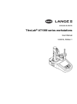
Figure 1-1
16196A/B/C/D Contents
Chapter 1
11
1. Installation Guide
Installation Guide
Incoming Inspection
Installation Guide
Incoming Inspection
Table 1-1
16196A Package Contents
No.
Description
Keysight Part No.
Qty.
1
16196A Parallel Electrode SMD Test Fixture
-
1
-
Insulator Assembly φ1.34 *1
16196-60112
1
2
Insulator Assembly φ1.14
16196-60113
1
2
Insulator Assembly φ1.08
16196-60114
1
3
Open Plate *2
16196-29002
1
4
Short Plate *2
16196-29026
1
5
Push Ring
16196-24004
1
6
Tweezers*3
8710-2081
1
7
Cleaning Rod
5182-7586
1
8
Wrench
8710-0909
1
9
Magnifying Glass*3
16193-60002
1
10
Carrying Case
16196-60150
1
11
Operation and Service Manual (This manual)*4
16196-90040
1
*1. Mounted in the Test Fixture when shipped from the factory.
*2.The Open Plate and Short Plate are packed in a single case and shipped.
*3.Furnished with Option 710.
*4.Furnished with Option ABA.
Table 1-2
16196B Package Contents
No.
Description
Keysight Part No.
Qty.
1
16196B Parallel Electrode SMD Test Fixture
-
1
-
Insulator Assembly φ0.85 *1
16196-60212
1
2
Insulator Assembly φ0.75
16196-60213
1
2
Insulator Assembly φ0.68
16196-60214
1
3
Open Plate *2
16196-29002
1
4
Short Plate *2
16196-29027
1
5
Push Ring
16196-24004
1
6
Tweezers*3
8710-2081
1
7
Cleaning Rod
5182-7586
1
8
Wrench
8710-0909
1
12
Chapter 1
Table 1-2
16196B Package Contents
No.
Description
Keysight Part No.
Qty.
9
Magnifying Glass*3
16193-60002
1
10
Carrying Case
16196-60250
1
11
Operation and Service Manual (This manual)*4
16196-90040
1
*1.Mounted in the Test Fixture when shipped from the factory.
*2.The Open Plate and Short Plate are packed in a single case and shipped.
*3.Furnished with Option 710.
*4.Furnished with Option ABA.
Table 1-3
16196C Package Contents
No.
Description
Keysight Part No.
Qty.
1
16196C Parallel Electrode SMD Test Fixture
-
1
-
Insulator Assembly φ0.48 *1
16196-60312
1
3
Open Plate *2
16196-29002
1
4
Short Plate*2
16196-29028
1
5
Push Ring
16196-24004
1
6
Tweezers*3
8710-2081
1
7
Cleaning Rod
5182-7586
1
8
Wrench
8710-0909
1
9
Magnifying Glass*3
16193-60002
1
10
Carrying Case
16196-60350
1
11
Operation and Service Manual (This manual)*4
16196-90040
1
*1.Mounted on the Test Fixture when shipped from the factory.
*2.The Open Plate and Short Plate are packed in a single case and shipped.
*3.Furnished with Option 710.
*4.Furnished with Option ABA.
Table 1-4
16196D Package Contents
No.
Description
Keysight Part No.
Qty.
1
16196D Parallel Electrode SMD Test Fixture
-
1
-
Insulator Assembly φ0.30 *1
16196-60414
1
2
Insulator Assembly φ0.34
16196-60412
1
3
Open Plate *2
16196-29002
1
Chapter 1
13
1. Installation Guide
Installation Guide
Incoming Inspection
Installation Guide
Incoming Inspection
Table 1-4
16196D Package Contents
No.
Description
Keysight Part No.
Qty.
4
Short Plate *2
16196-29030*3
1
5
Push Ring
16196-24004
1
6
Tweezers*4
8710-2081
1
7
Cleaning Rod
5182-7586
1
8
Wrench
8710-0909
1
9
Magnifying Glass*4
16193-60002
1
10
Carrying Case
16196-60450
1
11
Operation and Service Manual (This manual)*5
16196-90040
1
*1.Mounted in the Test Fixture when shipped from the factory.
*2.The Open Plate and Short Plate are packed in a single case and shipped.
*3.The part number is different from that of the replacement part. When you order it for user maintenance, refer to Table 6-1 on page 69.
*4.Furnished with Option 710.
*5.Furnished with Option ABA.
14
Chapter 1
Connecting the 16196A/B/C/D to a Measuring Instrument
To connect the 16196A/B/C/D Test Fixture to a measuring instrument, it is necessary to use
an adapter that fits the measuring instrument.
The 16196A/B/C/D Test Fixture is suitable for use with a high frequency LCR Meter or
Impedance Analyzer. Table 1-5 lists the appropriate combination of measuring instrument
and adapter.
Table 1-5
Measuring Instruments and Adapters
Instrument
Adapter
4287A
Test Head + Test Fixture Stand (Furnished with the 4287A)
E4991A
Test Head (Furnished with the E4991A)
4291A/B
Test Station + Test Head (Furnished with the 4291A/B)
4286A
Test Head + Test Fixture Stand (Furnished with the 4286A)
4395A*1
43961A Impedance Test Adapter
4396B*1
43961A Impedance Test Adapter
*1."Option 010 Impedance Measuring Function" is required.
16196A/B/C/D Test Fixture can be connected to instruments with the 4-terminal pair
configuration.
Table 1-6
Measuring Instruments and Adapters
Instrument
Adapter
4294A
42942A Terminal Adapter
4194A
41941A + 16099A or 41941B + 16099A
4192A, 4194A,
4263B, 4268A,
4278A, 4279A,
4284A, 4285A
16085B Terminal Adapter
Refer to the adapter’s manual about the procedure for connecting to the measuring
instrument.
NOTE
Some instruments require calibration at the 7-mm connector. Perform calibration at the
7-mm connector before connecting a test fixture. See the operation manual of the
instrument for more details.
Chapter 1
15
1. Installation Guide
Installation Guide
Connecting the 16196A/B/C/D to a Measuring Instrument
Installation Guide
Connecting the 16196A/B/C/D to a Measuring Instrument
The general procedure for mounting the Test Fixture on the adapter is as shown below. (For
details, see the Manual supplied with each adapter.)
Step 1. Turn the adapter's 7-mm connector in the counterclockwise direction when viewed from
above and screw the connection sleeve in fully.
Step 2. Align the text fixture with the adapter's mount post and 7-mm connector and set it gently in
place.
Step 3. Turn the adapter's 7-mm connector counterclockwise, connecting the bottom of the test
fixture with the connector.
NOTE
To make a firm connection with the test fixture, use the torque wrench (size: 3/4 inch,
torque: 12 lb-in, Keysight part number: 8710-1766) to fasten the adapter's 7-mm connector.
Figure 1-2
Installing the Test Fixture
16
Chapter 1
2. Product Overview
Product Overview
2
Product Overview
Product Overview
Product Overview
The 16196A, 16196B, 16196C, and 16196D are test fixtures for measuring chip
components. They enable chip type capacitors, inductors and other components to be
measured with high precision and measurement repeatability. The 16196A/B/C/D also is
compatible with measuring frequencies up to 3 GHz. The 16196A is for size 1608 parts *1,
the 16196B is for size 1005 parts *1, the 16196C is for size 0603parts *1, and the 16196D is
for size 0402 parts*1.
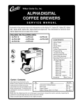
Figure 2-1
Product Overview (The photograph shows the 16196B.)
The product appearance is the same for the 16196A, 16196B and 16196C. Only the cap
shape for the 16196D is different.
*1.These sizes, 1608, 1005, 0603, and 0402, are all nominal sizes in millimeters.
18
Chapter 2
Product Overview
Product Overview
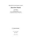
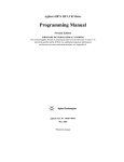
Figure 2-2
Electrode Structure
2. Product Overview
After passing through the DUT (Device Under Test), the current flows to the outer
conductor via the cap electrode and returns to the outer conductor of the 7-mm connector.
Through this structure, the ideal shield structure is formed.
Chapter 2
19
Product Overview
Product Overview
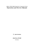
Functions
The names of each part of the 16196A/B/C/D are shown in Figure 2-3.
Figure 2-3
Names of Parts
Table 2-1
No.
Names of Parts and Functions
Name
Function
1
Cap
This is the LOW side electrode.
2
DUT Insertion Hole
Forms a cylindrical structure made with an insulator
and holds the DUT from the sides.
3
Magnifying Glass*1*2
Enlarges the DUT and the insulator hole area.
*1.Furnished with Option 710.
*2.The magnifying glass is packed separately from the 16196A/B/C/D body. Connect it as
shown in Figure 2-3.
20
Chapter 2
Product Overview
Product Overview
Names of Accessories and Functions
Accessories
Table 2-2
Names of Accessories and Functions
2. Product Overview
Figure 2-4
No.
Name
Function
1
Open Plate
Used when correcting for an open circuit.
2
Short Plate
Used when correcting for a short circuit.
3
Insulator Assembly
Used to change assemblies when measuring
DUTs with different shapes.
4
Push Ring
Supplementary tool used when removing DUTs.
5
Cleaning Rod
Cleans the electrodes.
6
Wrench
For removing hex nuts.
7
Tweezers*1
Used to handle the open plate, short plate, and
DUTs, etc.
*1.Frnished with Option 710.
Chapter 2
21
Product Overview
Product Overview
Insulator Assembly
In order to handle DUTs with differing shapes, the 16196A and 16196B each come with 3
types of insulator assembly, the 16196C comes with 1 insulator assembly, and the 16196D
comes with two types of insulator assembly. Each of these insulator assemblies has little
marks engraved in them to enable identification of each model and hole diameter. There
are marks on the back of the insulator assemblies to identify the model and there are marks
on the front to identify the hole diameter.
Insulator Assembly identifications
Keysight
Model No.
Back
Front
16196A
16196B
16196C
16196D
22
Chapter 2
3. Operation
3
Operation
This chapter describes preparations and fixture compensation when using the
16196A/B/C/D to take measurements as well as DUT connection and measuring methods.
Operation
Flow of Measurements
Flow of Measurements
Follow the steps below when performing measurements of DUTs with the 16196A/B/C/D.
1. Selecting and Changing the Insulator Assembly
Select an insulator assembly that is appropriate for the shape of the measured DUT and
replace the insulator assembly in the fixture.
2. Setting the Electrical Length
Set the fixture's electrical length in the measuring instrument you will be using.
3. Perfoming Fixture Compensation
Measure the data for open compensation and measure the data for short compensation.
When performing measurements with higher precision, carry out "Fixture
compensation for higher precision measurements".
4. Connecting and Measuring the DUT
Connect the DUT and perform measurements.
Settings of the electrical length and fixture compensation differ depending on the
measuring instrument used. Refer to the Operation Manual for the measuring instrument
that you are using.
NOTE
The 16196A/B/C/D requires frequent wear checks to keep the best measurement accuracy.
When the equipment is used for the first time following purchase or part replacement,
“Wear Check” should be conducted. Refer to “Wear Check” on page 44 for details.
24
Chapter 3
Operation
Selecting and Changing the Insulator Assembly
Selecting and Changing the Insulator Assembly
Select an insulator assembly that corresponds to the shape of the DUT being measured and
replace the insulator assembly in the fixture..
CAUTION
An exclusive type of insulator assembly is supplied with each model. Do not use an
insulator assembly from a different model.
Step 1. Select an insulator assembly that is appropriate for the shape of the DUT to be measured.
To take accurate and repeatable measurements, it is necessary for the DUT to be placed in
the DUT insertion hole and be stable. For that reason, the 16196A and 16196B each are
provided with 3 types of insulator assembly which have DUT insertion holes with different
diameters (the 16196C has only one type of insulator assembly, and the 16196D has two
types of insulator assembly). Select an insulator assembly that will create the narrowest
gap between the DUT and the DUT insertion hole.
DUT and DUT Insertion Hole Diameter
Table 3-1
Insulator Assembly Specifications
3. Operation
Figure 3-1
Insulator
Assembly
16196A
Chapter 3
Example of Corresponding Chip (mm)
Length (L)
Width (W)
Height (H)
φ1.34
1.6
0.8
0.8
φ1.14
1.6
0.8
0.6
φ1.08
1.6
0.8
0.5
25
Operation
Selecting and Changing the Insulator Assembly
Table 3-1
Insulator Assembly Specifications
Insulator
Assembly
Example of Corresponding Chip (mm)
Length (L)
Width (W)
Height (H)
φ0.85
1.0
0.5
0.5
φ0.75
1.0
0.5
0.35
φ0.68
1.0
0.5
0.35
16196C
φ0.48
0.6
0.3
0.3
16196D
φ0.30
0.4
0.2
0.13 or
16196B
0.2*1
φ0.34
0.4
0.2
0.2*1
*1.When you measure a 0.4 x 0.2 x 0.2 DUT, first check whether it
fits in the φ0.30 insulator assembly. Only if it does not, use the
φ0.34 insulator assembly.
NOTE
The number of the insulator assembly doesn’t indicate the maximum diameter of the DUT
insertion hole that can insert the cylindrical device.
NOTE
If the gap between the DUT and the insulator is large, the measurement accuracy and
repeatability decrease. Select an insulator assembly that is appropriate for the shape of the
DUT to be measured.
26
Chapter 3
Operation
Selecting and Changing the Insulator Assembly
Step 2. Replace the insulator assembly in the fixture with the selected insulator assembly.
Loosen the 2 screws used to fasten the insulator assembly with the hex wrench and take
them out, then remove the insulator assembly.
Removing the Insulator Assembly
NOTE
If the insulator assembly is difficult to remove, turn the fixture over and remove the
insulator assembly by letting it fall out.
CAUTION
There is danger of the measuring precision and repeatability being adversely affected, and
thus do not touch the lower electrode with your hands or damage it in any way.
3. Operation
Figure 3-2
Chapter 3
27
Operation
Selecting and Changing the Insulator Assembly
Step 3. Mount the insulator assembly you have selected, and tighten the screws to secure it. Be
sure to contact the insulator assembly with the bottom surface securely before tightening
the screws.
Figure 3-3
Installing the Insulator Assembly
Step 4. Connect the test fixture to the measuring instrument.
Connect the test fixture to the instrument in accordance with “Connecting the
16196A/B/C/D to a Measuring Instrument” on page 15 in Chapter 1.
28
Chapter 3
Operation
Setting the Electrical Length
Setting the Electrical Length
Set the electrical length in the measuring instrument. For the electrical length setting
method, see the Operation Manual for the measuring instrument you are using. The
electrical lengths for the 16196A/B/C/D are as shown below.
Table 3-2
Electrical Length
Model
Electrical Length [mm]
16196A
26.2
16196B
26.9
16196C
27.1
16196D
27.3
3. Operation
Chapter 3
29
Operation
Performing Fixture Compensation
Performing Fixture Compensation
In order to perform more accurate measurements, before beginning the measurement
procedure, it is necessary to compensate the fixture. For the 16196A/B/C/D, perform
measurements of the data for open compensation and of the data for short compensation.
NOTE
The 16196A/B/C/D requires frequent wear checks to keep the best measurement accuracy.
When the equipment is used for the first time following purchase or part replacement,
“Wear Check” should be conducted. Refer to “Wear Check” on page 44 for details.
NOTE
If there are temperature fluctuations which exceed a temperature range of ±5°C after
fixture compensation has been carried out, then perform fixture compensation again.
Measuring Open Compensation Data
Set the fixture in the open state using the open plate supplied.
Step 1. Remove the cap.
CAUTION
Make sure there is no dirt or other foreign matter in the DUT insertion hole.
Step 2. Using the Tweezers, place the open plate on top of the insulator assembly. Set the open
plate with the protruding surface down.
CAUTION
Handle the open plate with Tweezers. If dirt, etc. gets on it, measuring precision and
repeatability may be adversely affected.
30
Chapter 3
Operation
Performing Fixture Compensation
Figure 3-4
Setting the Open State Using the Open Plate
Step 4. Take measurements of the data for open compensation in accordance with the Operation
Manual for the measuring instrument you are using.
Chapter 3
31
3. Operation
Step 3. Fit the cap in place with the mark toward the front, and turn it to the right until it is locked.
Operation
Performing Fixture Compensation
Measuring Short Compensation Data
Set the fixture in the short state using the short plate supplied.
Step 1. Remove the cap. Take out the open plate used to measure the open compensation data.
CAUTION
Make sure there is no dirt or other foreign matter in the DUT insertion hole.
CAUTION
An exclusive type of short plate is supplied with each model. Do not use a short plate from
a different model.
Step 2. Place the short plate on the insulator assembly with tweezers. Place the rod-shaped
protrusion of the short plate downward, and insert it into the DUT insertion hole.
CAUTION
Handle the short plate with Tweezers. If dirt, etc. gets on it, measuring precision and
repeatability may be adversely affected.
Figure 3-5
Setting the Short State Using the Short Plate
Step 3. Fit the cap in place with the mark toward the front, and turn it to the right until it is locked.
Step 4. Take measurements of the data for short compensation in accordance with the Operation
Manual for the measuring instrument you are using.
32
Chapter 3
Operation
Performing Fixture Compensation
NOTE
Residual inductance for the Short Plate is as follows.
Model
Residual Inductance [nH]
16196A
0.43
16196B
0.27
16196C
0.16
16196D
0.11
3. Operation
Chapter 3
33
Operation
Connecting and Measuring DUTs
Connecting and Measuring DUTs
Connect DUTs to the electrodes and take measurements.
CAUTION
Do not connect a DUT, which has an incompatible size.
Step 1. Remove the cap.
CAUTION
Make sure there is no dirt or other foreign matter in the DUT insertion hole.
Step 2. Insert the DUT into the insulator hole with tweezers.
Use a magnifying glass to check that the DUT is inserted deeply enough into the insulator
hole for it to contact the bottom electrode.
Figure 3-6
Connecting a DUT
Step 3. Fit the cap in place with the mark toward the front, and turn it to the right until it is locked.
Step 4. Take measurements in accordance with the Operation Manual for the measuring instrument
you are using.
Removing the DUT
Use the push ring when removing the DUT.
34
Chapter 3
Operation
Connecting and Measuring DUTs
Figure 3-7
Removing the DUT Using the Push Ring
Chapter 3
35
3. Operation
Press the insulator assembly down using the push ring. When this is done, the lower
electrode will push up the DUT and you will be able to remove it. Measurements can also
be taken with the push ring placed as is on the insulator assembly.
Operation
Connecting and Measuring DUTs
36
Chapter 3
4. User Maintenance
User Maintenance
4
User Maintenance
Overview
Overview
The Necessity of User Maintenance
The measurement performance of the fixture decreases slightly each time measurement is
repeated. This is due to contamination of the contacting sections by solder, etc. and mechanical
wear and distortion caused by repeated use. Consequently, to maintain satisfactory measurement
results, it is important to maintain the contacting sections in good condition and take appropriate
measures before wear or distortion occurs. To accomplish this it is necessary to monitor the fixture
and perform maintenance of the various items as described in “User Maintenance Flow” on
page 39.
Because deterioration of the fixture seriously affects the measurement results when
measuring minute values or performing measurements with a high accuracy, proper
maintenance of the fixture is particularly important in these cases. Depending on the
required measurement performance, it may be necessary to take measures such as
establishing more rigorous evaluation standards and perform maintenance more frequently.
The upper and lower electrodes and the short plate are consumable products. These are the
fixture construction parts that tend to have the greatest effect on the measurement results.
During measurement, solder from the DUT tends to adhere to the upper and lower electrodes,
causing gradual deterioration of the electrodes. The short plate part is used for creating a
zero-standard during fixture compensation and distortion or contamination of the short plate
therefore directly affects the measurement result. Focusing on the upper and lower electrodes
and the short plate, this chapter explains the general aspects of user maintenance.
38
Chapter 4
User Maintenance
Overview
User Maintenance Flow
Figure 4-1 shows the flowchart of the user maintenance. The overview of the each
maintenance item is explained below.
Table 4-1
Maintenance Items
Item
Frequency
Item
Cleaning
Several times daily
Cleaning of fixture
Setting the user limit
When the product is
received and when you
need
Set the user limit to the required
measurement accuracy and the
measurement condition.
Measuring reference
value
When the product is
received and after parts
replacement
Measure Ls and Rs of the fixture
and set it the reference value
Measuring impedance
daily and before fixture
compensation
Measure Ls and Rs of the fixture
and calculate the shift from the
reference value.
Parts Replacement
When the wear check is
failed.
Replacement of worn parts
Assembling Check
After parts replacement
Measure Ls and Rs to confirm
that the fixture is assembled
correctly.
Wear Check
shift
4. User Maintenance
Chapter 4
39
User Maintenance
Overview
Figure 4-1
Flowchart of User Maintenance
40
Chapter 4
User Maintenance
Cleaning
Cleaning
If the electrodes and insulator assembly become dirty, measuring accuracy and
repeatability will decrease. Also, if dirt adheres to the surfaces of the body, it will become
impossible to remove the cap smoothly. In order to ensure measurement with high
accuracy, be sure to perform cleaning periodically.
Places Requiring Cleaned
Place, which need to be cleaned, are as follows.
Figure 4-2
•
Upper Electrode (Figure 4-2 (1))
•
Cap Inside (Figure 4-2 (2))
•
Lower Electrode (Figure 4-2 (3))
•
Insulator Assembly recessed part (Figure 4-2 (4))
•
Body side surfaces (Figure 4-2 (5))
•
Short Plate
•
Open Plate
Places to be Cleaned
4. User Maintenance
Chapter 4
41
User Maintenance
Cleaning
Cleaning Methods
Upper Electrode (Figure 4-2 (1)), Insulator Assembly (Figure 4-2 (4)), Open Plate,
Short Plate
Use the Cleaning Rod (Keysight parts number 5182-7586) for the cleaning. Use the white
rubber part of the cleaning rod to remove dirt from all contacting surfaces of the
above-mentioned parts. Be careful not to scratch or damage the parts when removing the
dirt.
Figure 4-3
Cleaning Rod
Dirt tends to adhere to the upper electrode and short plate parts in particular. Meticulous
cleaning of these parts is recommended.
CAUTION
The front of the short plate has a sharp edge, so take adequate precautions when cleaning it.
CAUTION
Do not use a file or similar object to remove dirt, as this will affect measurement accuracy
and repeatability.
NOTE
If the dirt cannot be removed, replace the part. For replacement method, see the sections
"Replaceable Parts" and "Replacement Procedure".
Lower Electrode (Figure 4-2 (3))
Use the Cleaning Rod (Keysight parts number 5182-7586) for the cleaning.First use the
push ring to press down the insulator assembly. While maintaining this condition, use the
white rubber part of the cleaning rod to remove dirt from the contacting parts of the lower
electrode. Be careful not to scratch or damage the parts when removing the dirt.
Dirt tends to adhere to the lower electrode parts in particular. Meticulous cleaning of these
parts is recommended.
CAUTION
Do not use a file or similar object to remove dirt, as this will affect measurement accuracy
and repeatability.
NOTE
If the dirt cannot be removed, replace the part. For replacement method, see the sections
"Replaceable Parts" and "Replacement Procedure".
42
Chapter 4
User Maintenance
Cleaning
Cap Inside (Figure 4-2 (2)), Body Side Surfaces (Figure 4-2 (5))
Wipe dirt off using a soft cloth, etc.
NOTE
When removing dirt, always be careful to clean so that the electrodes and insulator
assembly are not damaged.
4. User Maintenance
Chapter 4
43
User Maintenance
Wear Check
Wear Check
The wear check allows you to obtain an idea about the deterioration of the fixture in order
to ensure that the desired measurement accuracy is obtained. This check comprises “User
Limit Setting”, “Reference Value Acquisition” and “Measuring Impedance Shift”. Using a
desired frequency, the impedance (Rs, Ls) of the fixture itself is measured. It is
recommended to use a frequency that is also used under the conditions where the fixture is
normally used.
Normally, “User Limit Setting” should be conducted under the following circumstances.
•
•
When the equipment is used for the first time following purchase.
When the required measurement accuracy is changed.
Normally, “Reference Value Acquisition” should be conducted under the following
circumstances.
•
•
When the equipment is used for the first time following purchase.
Following replacement of parts.
Normally, “Measuring Impedance Shift” should be conducted under the following
circumstances.
•
Once daily and before fixture compensation is performed.
Example of User Limit Values Setting
It is necessary to decide wear check user limit values suitable for the DUT and the
demanded measurement accuracy. An example follows below.
To measure the inductors L: 10 nH and Q: 10 at a frequency (f) of 100 MHz with a
measurement accuracy degree of 20%;
L:
10 nH
Q:
10
Frequency:
Demanded Accuracy:
100 MHz
20% for both L and Q
Using the above conditions, the inductor’s reactance X and resistance R are determined in
the following manner.
X = 2πfL = 6 Ω
R = X ⁄ Q = 0.6 Ω
From Q = X ⁄ R = 2πfL ⁄ R we understand that when R changes 20% (100 mΩ) Q
should be approximately 20%, and when L changes 20% (2 nH), L and Q both change
20%. Accordingly, in order to measure both L and Q with a measurement accuracy of 20%
or less, at least the error of L and R must be less than 2 nH and 120 mΩ, respectively.
While remembering that L and R change together and keeping in mind other error factors
than the deterioration of the fixture, the respective values should be set to 25% in this
example, i.e., 500 pH and 30 mΩ.
44
Chapter 4
User Maintenance
Wear Check
CAUTION
Use the same user limit values for “Measuring Impedance Shift”.
NOTE
The above is just an example. The methods to determine the user limit vary with the
measurement conditions and the DUT, etc.
NOTE
In actually testing, a part of the effect of electrode wear is cancelled by the SHORT
compensation. It is recommended, however, to set the user limit as shown in this example
as the deviation from the reference value can be used to deal with all the things affecting
the measured values.
Please enter the user limit values in the “Check Sheet” (page 50, page 51). See “Check
Sheet Fill-Out Example” on page 49 for an example of how this is done.
4. User Maintenance
Chapter 4
45
User Maintenance
Wear Check
Reference Value Acquisition
The impedance (Rs, Ls) of the fixture itself should be measured before deterioration sets
in. It is recommended to use a measurement frequency that is used under the conditions
where the fixture is normally used.
Normally, the reference value should be measured under the following circumstances.
•
•
When the product is introduced.
Following replacement of parts.
Required Tools
•
•
•
1.5-mm hex wrench (provided accessory)
Short plate (provided accessory)
Impedance measuring instrument (with 7-mm connector and calibrated)
Table 4-2
Setting of Measuring Instrument
Measurement
Condition
Set Value
Electrical Length
16196A: 26.2 mm
16196B: 26.9 mm
16196C: 27.1 mm
16196D: 27.3 mm
Measurement Parameter
Ls, Rs
OSC Level
500 mV
Point Averaging
32
NOTE
To make the same settings as given in the above table, refer to the Operation Manual for
the measuring instrument.
CAUTION
The measuring instrument’s fixture compensation function should be set to OFF.
Acquisition Procedure (Electrode Wear Check Reference Value)
Step 1. Remove the cap and ensure that nothing is inserted into the fixture.
Step 2. Clean the fixture’s upper and lower electrodes as described in “Cleaning” on page 41.
Step 3. Connect the fixture to the 7-mm connector.
Step 4. Place the cap on the fixture body.
Step 5. In order to contact the upper electrode and the lower electrode, use the provided hex
wrench to turn the screw at the top of the cap approximately 6 turns to the left.
NOTE
In case of the 16196D, please omit the step 5.
Step 6. Measure Rs and Ls as described in the Operation Manual for the measuring instrument.
46
Chapter 4
User Maintenance
Wear Check
Step 7. Record the read values as the reference values in the “Check Sheet” (page 50).
Step 8. Calculate the upper limit value and the lower limit value from the previously set user limits
and the reference values obtained here. Record these in the "Check Sheet".
Step 9. Tighten the screw on top of the cap loosened in Step 5.
NOTE
In case of the 16196D, please omit the step 9.
Acquisition Procedure (Short Plate Wear Check Reference Value)
Step 1. Clean the short plate as described in “Cleaning” on page 41.
Step 2. Remove the cap and place the short plate with the protruding surface down on the insulator
assembly.
Step 3. Place the cap on the fixture body.
Step 4. Measure Rs and Ls as described in the Operation Manual for the measuring instrument.
Step 5. Record the read values as the reference values in the “Check Sheet” (page 51).
Step 6. Calculate the upper limit value and the lower limit value from the previously set user limits
and the reference values obtained here. Record these in the "Check Sheet".
4. User Maintenance
Chapter 4
47
User Maintenance
Wear Check
Measuring Impedance Shift
Measuring the impedance of the fixture with the upper and lower electrodes in contact
should check the electrode wear.
Normally, this check should be conducted under the following circumstances.
•
Once daily and before fixture compensation.
Required Tools
•
•
CAUTION
1.5-mm hex wrench (provided accessory)
Impedance measuring instrument (with 7-mm connector and calibrated)
The measuring instrument’s fixture compensation function should be set to OFF. Also,
other settings should be the same as those used for “Reference Value Acquisition”.
Procedure (Electrode Wear Check)
Step 1. Clean the electrodes as described in “Cleaning” on page 41.
Step 2. Set the measuring instrument and measure in the same way as for “Acquisition Procedure
(Electrode Wear Check Reference Value)” on page 46.
Step 3. Record the Rs and Ls measured values as pass-fail in the “Check Sheet” (page 50).
Step 4. If the result is unacceptable, replace both the upper and the lower electrode.
Procedure (Short Plate Wear Check)
Step 1. Clean the short plate as described in “Cleaning” on page 41.
Step 2. Set the measuring instrument and measure in the same way as for “Acquisition Procedure
(Short Plate Wear Check Reference Value)” on page 47.
Step 3. Enter the Rs and Ls measured values as pass-fail in the “Check Sheet” (page 51).
Step 4. If the result is unacceptable, replace the short plate.
48
Chapter 4
User Maintenance
Check Sheet
Check Sheet
Check Sheet Fill-Out Example
The following example shows how the check sheet is filled out following electrode wear
check. Fill out the sheet in the same manner for short plate wear check.
Electrode Wear Check Fill-Out Example
Table 4-3
Frequency*1
100 MHz
800 MHz
Reference Value and User Limit Values Fill-Out Example
Measurement
Parameter
User Limit
Value*3 [b]
Reference
Value*2 [a]
Lower Limit
[a-b]
Upper Limit
[a+b]
120
Rs
90
mΩ
30
mΩ
60
mΩ
Ls
−290
pH
500
pH
−790
pH
Rs
310
mΩ
40
mΩ
270
mΩ
Ls
−260
pH
400
pH
−660
pH
mΩ
210
350
pH
mΩ
140
pH
*1.Set by the user as desired.
*2.Record values obtained at the time of “Reference Value Acquisition” on page 46.
*3.See also “Example of User Limit Values Setting” on page 44.
Table 4-4
Check History Fill-Out Example
Frequency
Measurement
parameter
Measured Value
Pass/Fail
Oct./11/1999
9:30
100 MHz
Rs
100
mΩ
Pass
Ls
−320
pH
Pass
Oct./11/1999
9:35
800 MHz
Rs
345
mΩ
Pass
Ls
−360
pH
Pass
Oct./12/1999
9:30
100 MHz
Rs
105
mΩ
Pass
Ls
−340
pH
Pass
Oct./12/1999
9:35
800 MHz
Rs
355
mΩ
Fail*1
Ls
−320
pH
Pass
4. User Maintenance
Date
*1.When the result is unacceptable, replace the part.
Chapter 4
49
User Maintenance
Check Sheet
Electrode Wear Check
Table 4-5
Frequency
Table 4-6
Reference Value and User Limit Values
Measurement
Parameter
Reference Value
[a]
User Limit Value
[b]
Lower Limit
[a - b]
Upper Limit
[a + b]
Rs
mΩ
mΩ
mΩ
mΩ
Ls
pH
pH
pH
pH
Rs
mΩ
mΩ
mΩ
mΩ
Ls
pH
pH
pH
pH
Check History
Date
50
Frequency
Measurement
Parameter
Measured Value
Pass/Fail
Rs
mΩ
Ls
pH
Rs
mΩ
Ls
pH
Rs
mΩ
Ls
pH
Rs
mΩ
Ls
pH
Rs
mΩ
Ls
pH
Rs
mΩ
Ls
pH
Rs
mΩ
Ls
pH
Rs
mΩ
Ls
pH
Rs
mΩ
Ls
pH
Rs
mΩ
Ls
pH
Rs
mΩ
Ls
pH
Rs
mΩ
Ls
pH
Rs
mΩ
Ls
pH
Rs
mΩ
Ls
pH
Rs
mΩ
Ls
pH
Rs
mΩ
Ls
pH
Chapter 4
User Maintenance
Check Sheet
Short Plate Wear Check
Table 4-7
Frequency
Table 4-8
Reference Value and User Limit Values
Measurement
Parameter
Reference Value
[a]
User Limit Value
[b]
Lower Limit
[a - b]
Upper Limit
[a + b]
Rs
mΩ
mΩ
mΩ
mΩ
Ls
pH
pH
pH
pH
Rs
mΩ
mΩ
mΩ
mΩ
Ls
pH
pH
pH
pH
Check History
Date
Measurement
Parameter
Measured Value
Pass/Fail
Rs
mΩ
Ls
pH
Rs
mΩ
Ls
pH
Rs
mΩ
Ls
pH
Rs
mΩ
Ls
pH
Rs
mΩ
Ls
pH
Rs
mΩ
Ls
pH
Rs
mΩ
Ls
pH
Rs
mΩ
Ls
pH
Rs
mΩ
Ls
pH
Rs
mΩ
Ls
pH
Rs
mΩ
Ls
pH
Rs
mΩ
Ls
pH
Rs
mΩ
Ls
pH
Rs
mΩ
Ls
pH
Rs
mΩ
Ls
pH
Rs
mΩ
Ls
pH
4. User Maintenance
Chapter 4
Frequency
51
User Maintenance
Parts Replacement
Parts Replacement
The replacement of parts is explained in the following.
Procedure for Replacement
Refer to “Replaceable Parts” on page 68 and “Replacement Procedure” on page 75 when
replacing parts.
A maintenance kit containing 5 pieces is available for replacement of upper and lower
electrodes and the short plate. For details, see “Maintenance Kit” on page 74.
Check Following Replacement
Following replacement of parts, it is necessary to confirm that the fixture has been
correctly assembled. Please conduct the “Assembling Check” on page 53.
52
Chapter 4
User Maintenance
Assembling Check
Assembling Check
Following replacement of parts, confirm that the fixture has been correctly assembled. The
assembling check consists of “Electrode Check” and “Short Plate Check”, Measure the
impedance (Rs, Ls) of both at 100 MHz and 1 GHz.
Normally, this check should be conducted under the following circumstances.
•
Following replacement of parts.
Electrode Check
It should be checked whether the fixture is correctly assembled by measuring the
impedance (Rs, Ls) of the fixture itself with the upper and lower electrodes in contact.
Required Tools
•
•
1.5-mm hex wrench (provided accessory)
Impedance measuring instrument (with 7-mm connector and calibrated)
Table 4-9
Setting of Measuring Instrument
Measurement
Condition
Set Value
Electrical Length
16196A: 26.2 mm
16196B: 26.9 mm
16196C: 27.1 mm
16196D: 27.3 mm
Ls, Rs
OSC Level
500 mV
Point Averaging
32
To make the same settings as given in the above table, refer to the Operation Manual for
the measuring instrument.
Procedure
Step 1. Remove the cap and ensure that nothing is inserted into the fixture.
Step 2. Clean the fixture’s upper and lower electrodes as described in “Cleaning” on page 41.
Step 3. Connect the fixture to the 7-mm connector.
Step 4. Place the cap on the fixture body.
Step 5. In order to contact the upper electrode and the lower electrode, use the provided hex
wrench to turn the screw on the top of the cap approximately 6 turns to the left.
Chapter 4
53
4. User Maintenance
NOTE
Measurement Parameter
User Maintenance
Assembling Check
NOTE
In case of the 16196D, please omit the step 5.
Step 6. Measure Rs and Ls at 100 MHz and 1 GHz in this state.
Step 7. Confirm that the Rs and Ls values are within the limits given in the table below. If the
results are outside the limit range, first check the attachment of the upper and lower
electrode. If these are correctly attached but the results still remain outside the limit range,
the fixture main body may be damaged. In this case, please contact a Keysight
Technologies Sales or Service office.
Step 8. Tighten the screw on top of the cap loosened in Step 5.
NOTE
In case of the 16196D, please omit the step 8.
Table 4-10
Electrode Check and Limits (16196A)
Parameter
Frequency
Limit (Absolute value)
100 MHz
Rs
30 mΩ ∼ 150 mΩ
Ls
−500 pH ∼ 0 pH
Rs
100 mΩ ∼ 480 mΩ
Ls
−500 pH ∼ 0 pH
1 GHz
Table 4-11
Electrode Check and Limits (16196B)
Parameter
Frequency
Limit (Absolute value)
100 MHz
Rs
40 mΩ ∼ 160 mΩ
Ls
−400 pH ∼ 0 pH
Rs
120 mΩ ∼ 510 mΩ
Ls
−400 pH ∼ 0 pH
1 GHz
Table 4-12
Electrode Check and Limits (16196C)
Parameter
Frequency
Limit (Absolute value)
100 MHz
Rs
40 mΩ ∼ 170 mΩ
Ls
−300 pH ∼ 100 pH
Rs
120 mΩ ∼ 540 mΩ
Ls
−300 pH ∼ 100 pH
1 GHz
Table 4-13
Electrode Check and Limits (16196D)
Parameter
Frequency
Limit (Absolute value)
100 MHz
Rs
40 mΩ ∼ 250 mΩ
Ls
−300 pH ∼ 350 pH
54
Chapter 4
User Maintenance
Assembling Check
Table 4-13
Electrode Check and Limits (16196D)
Parameter
Frequency
Limit (Absolute value)
1 GHz
Rs
80 mΩ ∼ 810 mΩ
Ls
−300 pH ∼ 200 pH
4. User Maintenance
Chapter 4
55
User Maintenance
Assembling Check
Short Plate Check
Measuring the fixture’s impedance with the short plate in place should check the condition
of the short plate.
CAUTION
“Short Plate Check” should be performed after the “Electrode Check” has been completed.
Required Tools
•
•
1.5-mm hex wrench (provided accessory)
Impedance measuring instrument (with 7-mm connector and calibrated)
Table 4-14
Setting of Measuring Instrument
Measurement
condition
Set Value
Electrical Length
16196A: 26.2 mm
16196B: 26.9 mm
16196C: 27.1 mm
16196D: 27.3 mm
NOTE
Measurement Parameter
Ls, Rs
OSC Level
500 mV
Point Averaging
32
To make the same settings as given in the above table, refer to the Operation Manual for
the measuring instrument.
Procedure
Step 1. Clean the short plate as described in “Cleaning” on page 41.
Step 2. Remove the cap and place the short plate with the protruding surface down on the insulator
assembly.
Step 3. Place the cap on the fixture body and fasten it.
Step 4. Measure Rs and Ls at 100 MHz and 1 GHz in this condition.
Step 5. Confirm that the Rs and Ls values are within the representative values given in the table
below. If the results are outside the limit range, please replace the short plate.
56
Chapter 4
User Maintenance
Assembling Check
Table 4-15
Short Plate Check and Limits (16196A)
Parameter
Frequency
Limit (Absolute value)
100 MHz
Rs
30 mΩ ∼ 160 mΩ
Ls
200 pH ∼ 800 pH
Rs
100 mΩ ∼ 510 mΩ
Ls
200 pH ∼ 600 pH
1 GHz
Table 4-16
Short Plate Check and Limits (16196B)
Parameter
Frequency
Limit (Absolute value)
100 MHz
Rs
40 mΩ ∼ 170 mΩ
Ls
100 pH ∼ 600 pH
Rs
120 mΩ ∼ 540 mΩ
Ls
100 pH ∼ 400 pH
1 GHz
Table 4-17
Short Plate Check and Limits (16196C)
Parameter
Frequency
Limit (Absolute value)
100 MHz
Rs
40 mΩ ∼ 180 mΩ
Ls
100 pH ∼ 600 pH
Rs
120 mΩ ∼ 570 mΩ
Ls
50 pH ∼ 350 pH
1 GHz
Table 4-18
Short Plate Check and Limits (16196D)
Frequency
Limit (Absolute value)
100 MHz
Rs
30 mΩ ∼ 260 mΩ
Ls
50 pH ∼ 600 pH
Rs
80 mΩ ∼ 860 mΩ
Ls
0 pH ∼ 350 pH
1 GHz
Chapter 4
4. User Maintenance
Parameter
57
User Maintenance
Assembling Check
58
Chapter 4
5
Specifications and Supplemental
Performance Characteristics
5. Specifications and
Supplemental
Performance Characteristics
This chapter provides specifications and supplemental performance characteristics of the
16196A/B/C/D test fixture.
Specifications and Supplemental Performance Characteristics
Specifications
Specifications
Applicable Instruments
Refer to the Table 1-4,1-5.
Applicable DUT Type
Surface Mount Device with side electrodes.
Model
Length (L) × Width (W) × Height (H)
16196A
(1.6 ± 0.15) × (0.8 ± 0.15) × (0.4 to 0.95) mm
16196B
(1.0 ± 0.1) × (0.5 ± 0.1) × (0.3 to 0.6) mm
16196C
(0.6 ± 0.03) × (0.3 ± 0.03) × (0.27 to 0.33) mm
16196D
(0.4 ± 0.02) × (0.2 ± 0.02) × (0.11 to 0.22) mm
Frequency
DC to 3 GHz
Maximum Voltage
± 40V peak max. (AC+DC)
Maximum Current
5A
Operating
Environment
temp.
-55°C to +85°C
humidity
15% to 95%RH (@ wet bulb temp. < 40°C)
Non Operating
temp.
-55°C to +85°C
Environment
humidity
≤ 90 % RH (@ wet bulb temp. <65°C)
Dimension
78 (D) × 140 (W) × 48 (H) mm (nominal)
Weight
250g (nominal)
Safety Standards
Model
(nominal)
16196A
26.2 mm
16196B
26.9 mm
16196C
27.1 mm
16196D
27.3 mm
IEC 61010-1:2001 / EN 61010-1:2001
Canada: CAN/CSA C22.2 No. 1010.1-92
Installation/overvoltage category II
Pollution degree 2
Indoor use
60
Chapter 5
Specifications and Supplemental Performance Characteristics
Supplemental Performance Characteristics
Supplemental Performance Characteristics
This section provides useful data on the 16196A/B/C/D. These supplemental performance
characteristics should not be considered specifications.
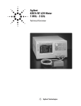
Additional Error
Additional errors are calculated as follows.
|Z| Measurement
Additional error for Impedance Ze [%] is calculated by substituting the values in the table
below into the following equation.
Ze [%] = ± {A + (Zs/Zx + Yo ×Zx) × 100}
where
A [%]
Test Fixture’s Proportional Error [%]
Yo [S]
Test Fixture’s Open Repeatability [S]
Zs [Ω]
Test Fixture’s Short Repeatability [Ω]
Zx [Ω]
Measured Impedance Value of DUT [Ω]
Zs
(30 + 125 × f ) × 10-3[Ω]
Yo
(5 + 40 × f ) × 10-6[S]
A
1 × f 2 [%]
where f is frequency (GHz).
D Measurement
Additional error for Dissipation Factor De is calculated by using the additional error for
Impedance Ze [%] as follows.
If Dx ≤ 0.1:
De = Ze / 100
If 0.1 < Dx ≤ 0.5:
De = (Ze / 100) × (1 + Dx)
where Dx is the measured value of D. It is necessary for Ze to be below 10 %.
NOTE
D is not expressed as a percentage but as an absolute value.
61
5. Specifications and
Supplemental
Performance Characteristics
Chapter 5
Specifications and Supplemental Performance Characteristics
Supplemental Performance Characteristics
Rs (ESR) Measurement
Additional error Rse[%] of the Rs measurement is calculated by using the additional error
for Impedance Ze [%] as follows.
If Dx ≤ 0.1:
Rse [%] = Ze / Dx
If 0.1 < Dx ≤ 0.5:
2
Rse [%] = (Ze / Dx) × ( 1 + Dx )
Dx is the measured value of D and is calculated as follows.
Dx = 2 × π × f × Csx × Rsx,
where
f: measurement signal frequency
Csx: measured value of Cs
Rsx: measured value of Rs.
Figure 5-1
Additional Error for Impedance
62
Chapter 5
Specifications and Supplemental Performance Characteristics
Supplemental Performance Characteristics
Residual Inductance
Residual inductance for the Short Plate is as follows.
Model
Residual Inductance [nH]
16196A
0.43
16196B
0.27
16196C
0.16
16196D
0.11
Applying loading weight to the DUT
The following table shows the factory default of loading weight on the DUT for each
model. For the 16196D, the user can replace a part (washer) inside the cap to change it. For
the 16196A/B/C, however the loading weight on the DUT cannot be changed.
Keysight model
number
Loading weight to the DUT [gf]
16196A/B/C
400
16196D
300
Changing the loading weight to the DUT for the 16196D
If the factory default loading weight damages the DUT, replace the part (washer) inside the
cap, which changes the spring pressure, to adjust the loading weight on the DUT.
Replacement washers must be prepared by users themselves.
NOTE
When the washer is replaced, the specifications and performance of this product are not
guaranteed.
Information required to create washers is given below.
Table 5-1
Material and size of the washer
Outer diameter
[mm]
Inner diameter
[mm]
Polyacetal
φ8.0 to φ12.0
φ3.2
63
5. Specifications and
Supplemental
Performance Characteristics
Chapter 5
Material
Specifications and Supplemental Performance Characteristics
Supplemental Performance Characteristics
Figure 5-2
Shape of the cap washer
Table 5-2
Relation between washer thickness and loading weight applied to the DUT
(design values)
t [mm]
Loading weight to the DUT:G [gf]
1.0
120
1.5
180
2.0
240
2.5
300
The loading weight applied to the DUT, G [gf], is obtained by substituting the values of t
[mm] into the following equation.
G [gf] = 119 x (3.55 + t ) - 420
NOTE
If a washer with a thickness (t) of less than 1.0 mm is used, measurement may not be
performed accurately.
64
Chapter 5
Specifications and Supplemental Performance Characteristics
Supplemental Performance Characteristics
Replacing the washer inside the cap
The procedure for replacing the washer inside the cap is described below.
Figure 5- 3
Exploded view of the cap
Replacement procedure
1. Locate a replacement washer.
2. Detach the cap from the fixture.
3. Detach [1] then [2] while holding [7].
4. Detach [3] and [4] from [7].
5. Detach [5] from [7], and replace it with the replacement washer.
6. Attach [4] detached in Step 4 to [7].
8. Clean [7]. (See “User Maintenance”of the Chapter , “Cleaning.”)
NOTE
Be careful not to bolt inside parts out of the cap when detaching/attaching [1] and [2],
because the spring [6] is powerfull.
Chapter 5
65
5. Specifications and
Supplemental
Performance Characteristics
7. While protruding [7] from [3], attach [2] detached in Step 3, and tighten [1] with a
tightening torque of 0.2 Kgf-cm (0.2 in-lb).
Specifications and Supplemental Performance Characteristics
Supplemental Performance Characteristics
66
Chapter 5
6. Service
6
Service
This chapter describes the proper maintenance of the fixture and parts replacement.
Service
Replaceable Parts
Replaceable Parts
Check the part number by the exploded view below. Do not disassemble the fixture beyond
what is shown in this exploded view.
To order parts, specify the Keysight part number. If the part, which is causing problems, is
a part that cannot be disassembled, please order the part, which the affected part is, a part
of. Sales and Service offices of Keysight Technologies also accept products for repairs.
Block Assembly
Figure 6-1
Block Assembly Exploded View
68
Chapter 6
Table 6-1
Replaceable Parts (Block Assembly)
Ref.
Desig.
Keysight Part No.
1
16196-60010
1
Cap Assembly (for 16196A/B/C)
16196-60020
1
Cap Assembly (for 16196D)
2
0515-1044
2
Cap Screw Mach M1.6
3
16196-60112
1
φ1.34 Insulator (for 16196A)
16196-60113
1
φ1.14 Insulator (for 16196A)
16196-60114
1
φ1.08 Insulator (for 16196A)
16196-60212
1
φ0.85 Insulator (for 16196B)
16196-60213
1
φ0.75 Insulator (for 16196B)
16196-60214
1
φ0.68 Insulator (for 16196B)
16196-60312
1
φ0.48 Insulator (for 16196C)
16196-60412
1
φ0.34 Insulator (for 16196D)
16196-60414
1
φ0.30 Insulator (for 16196D)
4
N/A
1
Ground Assembly
5*1
16196-60111
1
Lower Electrode (for 16196A)
16196-60211
1
Lower Electrode (for 16196B)
16196-60311
1
Lower Electrode (for 16196C)
16196-60411
1
Lower Electrode (for 16196D)
6
0515-0954
3
Screw M-2.5
7
16196-24001
1
Base
8
0515-0905
3
Screw M-2.5
9
16196-24004
1
Push Ring
10
16196-29002
1
Open Plate
11*1
16196-29026
1
Short Plate (for 16196A)
16196-29027
1
Short Plate (for 16196B)
16196-29028
1
Short Plate (for 16196C)
16196-65101
1
Short Plate (for 16196D)
Chapter 6
Qty.
Description
69
6. Service
Service
Replaceable Parts
Service
Replaceable Parts
Table 6-1
Replaceable Parts (Block Assembly)
Ref.
Desig.
Keysight Part No.
Qty.
Description
12
16196-00601
1
Plate (for 16196A)
16196-00611
1
Plate (for 16196B)
16196-00621
1
Plate (for 16196C)
16196-00632
1
Plate (for 16196D)
*1.Maintenance Kit consisting of 5 replaceable parts is available. Refer to “Maintenance Kit” on page 74 for details.
70
Chapter 6
Cap
Figure 6-2
Cap Exploded View (for 16196A/B/C)
Table 6-2
Replaceable Parts (Cap)
Ref.
Desig.
Keysight Part No.
Qty.
Description
1
0515-1044
1
Screw Mach M1.6
2
16196-24005
1
Stopper
3
N/A
1
Cap
4
1460-2618
1
Spring
5*1
16196-23008
1
Upper Electrode
*1.Maintenance Kit including 5 replaceable parts is available. Refer to “Maintenance
Kit” on page 74 for details.
Chapter 6
71
6. Service
Service
Replaceable Parts
Service
Replaceable Parts
Figure 6-3
Cap Exploded View (for 16196D)
Table 6-3
Replaceable Parts (Cap)
Ref.
Desig.
Keysight Part No.
Qty.
Description
1
0515-1077
1
Screw Mach M2
2
3050-2238
1
Washer
3
N/A
1
Cap
4
3050-2241
1
Washer
5
3050-2239
1
Washer
6
1460-2618
1
Spring
7*1
16196-23043
1
Upper Electrode
*1.Maintenance Kit including 5 replaceable parts is available. Refer to “Maintenance
Kit” on page 74 for details.
72
Chapter 6
Other Parts
Table 6-4
Replaceable Parts (Other Parts)
Ref.
Desig.
Keysight Part No.
1
16196-60150
1
Carrying Case (for 16196A)
16196-60250
1
Carrying Case (for 16196B)
16196-60350
1
Carrying Case (for 16196C)
16196-60450
1
Carrying Case (for 16196D)
2
16193-60002
2
Magnifying Glass
3
5182-7586
1
Cleaning Rod
4
8710-0909
1
Wrench 1.5 mm Hex
5
8710-2081
1
Tweezers
6
1540-0622
1
Case for OPEN and SHORT plate
7
9282-0114
1
Cushion
Chapter 6
Qty.
Description
73
6. Service
Service
Replaceable Parts
Service
Maintenance Kit
Maintenance Kit
The 16196U-maintenance kit is available to provide consumable products and replaceable
parts for the 16196A/B/C/D.
16196U Maintenance Kit
The 16196A/B/C/D common option and options for each model separately are available.
Table 6-5
16196A/B/C Common Option
Opt010
Table 6-6
Table 6-7
Table 6-8
Table 6-9
74
Upper Electrode Set for 16196A/B/C (5 pieces)
16196A Option
Opt100
1608(mm) Short Plate Set (5 pieces)
Opt110
1608(mm) Lower Electrode Set (5 pieces)
16196B Option
Opt200
1005(mm) Short Plate Set (5 pieces)
Opt210
1005(mm) Lower Electrode Set (5 pieces)
16196C Option
Opt300
0603(mm) Short Plate Set (5 pieces)
Opt310
0603(mm) Lower Electrode Set (5 pieces)
16196D Option
Opt020
Upper Electrode Set for 16196D (5 pieces)
Opt400
0402(mm) Short Plate Set (5 pieces)
Opt410
0402(mm) Lower Electrode Set (5 pieces)
Chapter 6
Replacement Procedure
This section describes the replacement methods for the lower electrode, insulator and
upper electrode. After replacing the respective parts, check the operation of the parts with
reference to "Operation Check."
To replace the insulator and upper electrode, the 1.5-mm hex wrench (Keysight Part No.
8710-0909), included with the fixture, is required.
Chapter 6
75
6. Service
Service
Replacement Procedure
Service
Replacement Procedure
Lower Electrode
1. Prepare the replacement center electrode.
2. Take out the 3 screws from the bottom of the fixture and take out the DUT insert.
Figure 6-4
Removing the Bottom of the Fixture
76
Chapter 6
3. Remove the lower electrode from the DUT insert.
Figure 6-5
Removing the Lower Electrode
4. Insert the replacement lower electrode in the DUT insert.
NOTE
The tip of the lower electrode is thin and easily bent. To prevent the tip of the lower
electrode from contacting the inside of the DUT insert and being bent, insert the lower
electrode vertically against the DUT’s bottom surface.
5. Insert the DUT insert in the bottom of the fixture so that the bottom screws settle into
the holes in the bottom of the fixture.
Chapter 6
77
6. Service
Service
Replacement Procedure
Service
Replacement Procedure
Figure 6-6
Mounting the DUT Insert
6. Fasten the DUT insert to the bottom of the fixture using the screws.
Insulator
Replace the insulator with reference to “Selecting and Changing the Insulator Assembly”
on page 25.
78
Chapter 6
Upper Electrode
1. Prepare the replacement electrode.
2. Remove the cap from the fixture.
3. Take out the screw from the top of the cap and remove the electrode from the cap.
NOTE
In case of the 16196D, take out the screw from the top of the cap while holding the
electrode.
4. Take the electrode out of the spring and insert the replacement electrode.
5. Push the electrode in from the bottom of the cap so that the top of the electrode
protrudes out of the top of the cap.
Figure 6-7
Electrode Replacement 1
Chapter 6
79
6. Service
Service
Replacement Procedure
Service
Replacement Procedure
6. Place the stopper removed in step 3 so that the protrusion in the bottom aligns with the
indent in the top of the electrode and tighten the screw.
NOTE
Figure 6-8
In case of the 16196D, while holding the electrode, attach the washer and tighten the screw.
The tightening torque is 0.2 Kgf-cm (0.2 in-lb).
Electrode Replacement 2
80
Chapter 6
Assembling Check
The assembling check need to be performed following replacement of parts. The
impedance measurement instrument or the network analyzer is required for the assembling
check. The impedance measurement instrument is more recommendable. Refer to
“Assembling Check” on page 53 for the procedure using the impedance measurement
instrument.
The assembly check methods with the network analyzer are explained in the following.
NOTE
The network analyzer can be used only for the assembling check. The network analyzer
has no function to measure DUT with the 16196A/B/C/D.
Method Using Network Analyzer
Required Tools
•
Keysight 8753E
•
Open plate
•
Short plate
Procedure
Step 1. Conduct S11 full-calibration with the 7-mm connector to be connected to the fixture.
NOTE
For details on the calibration method, see the User’s Guide for the measuring instrument.
Step 2. Connect the fixture to the measuring instrument.
Step 3. Remove the cap and place the open plate on the insulator assembly. Then attach and fasten
the cap.
Step 4. Set the measuring instrument as follows.
Measurement Parameter
Primary:Mag, Secondary:Phase
Power
−10 dBm
IF BW
100 Hz
Point Averaging
16
Port Extension
16196A: 26.2 mm
16196B: 26.9 mm
16196C: 27.1 mm
16196D: 27.3 mm
NOTE
For details on the setting and measurement procedures, see the User’s Manual for the
Chapter 6
81
6. Service
Service
Assembling Check
Service
Assembling Check
measuring instrument.
Step 5. Take Mag and Phase value readings at 100 MHz and 1 GHz and record the results. Check if
the Mag and Phase values are within the typical value ranges shown in the following table.
Table 6-10
Operation Check Typical Values (Open, common for 16196A/B/C/D)
Parameter
Frequency
Typical Value (Absolute value)
Mag
100 MHz
−0.2 ∼ 0.2
Mag
1 GHz
−0.2 ∼ 0.2
Phase
100 MHz
−0.5º ∼ 0.5º
Phase
1 GHz
−2.5º ∼ 2.5º
Step 6. Remove the open plate, and place the short plate on the insulator assembly. Then attach and
fasten the cap.
Step 7. Take Mag and Phase value readings at 100 MHz and 1 GHz in this short state and record
the results. Check if the Mag and Phase values are within the typical value ranges shown in
the following table.
Table 6-11
Table 6-12
Table 6-13
Operation Check Typical Values (Short, 16196A)
Parameter
Frequency
Typical Value (Absolute value)
Mag
100 MHz
−0.06 ∼ −0.01
Mag
1 GHz
−0.18 ∼ −0.03
Phase
100 MHz
178º ∼ 180º
Phase
1 GHz
171º ∼ 178º
Operation Check Typical Values (Short, 16196B)
Parameter
Frequency
Typical Value (Absolute value)
Mag
100 MHz
−0.06 ∼ −0.01
Mag
1 GHz
−0.19 ∼ −0.04
Phase
100 MHz
179º ∼ 180º
Phase
1 GHz
174º ∼ 180º
Operation Check Typical Values (Short, 16196C)
Parameter
Frequency
Typical Value (Absolute value)
Mag
100 MHz
−0.07 ∼ −0.01
Mag
1 GHz
−0.20 ∼ −0.04
Phase
100 MHz
179º ∼ 180º
Phase
1 GHz
174º ∼ 180º
82
Chapter 6
Table 6-14
Operation Check Typical Values (Short, 16196D)
Parameter
Frequency
Typical Value (Absolute value)
Mag
100 MHz
−0.15 ∼ 0
Mag
1 GHz
−0.40 ∼ 0
Phase
100 MHz
179º ∼ 180º
Phase
1 GHz
174º ∼ 180º
Chapter 6
83
6. Service
Service
Assembling Check
Service
Assembling Check
84
Chapter 6
Index
A
Accessories, 21
adapter, 15
Additional Error, 61
Assembling Check, 53
B
Body Side Surfaces
Cleaning Methods, 43
C
Cap
Cleaning Methods, 43
Functions, 20
Places Requiring Cleaning, 41
Replaceable Parts, 69
Carrying Case
16196A Package Contents, 12
16196B Package Contents, 13
16196C Package Contents, 13
16196D Package Contents, 14
Replaceable Parts, 73
certification, 4
Changes The Spring Pressure, 63
Check Sheet
Fill-Out Example, 49
Cleaning
Methods, 42
Places Requiring, 41
Cleaning Rod
16196A Package Contents, 12
16196B Package Contents, 12
16196C Package Contents, 13
16196D Package Contents, 14
Functions, 21
Replaceable Parts, 73
D
Dimension, 60
Documentation Warranty, 4
DUT
Connecting and Measuring, 34
Removing, 34
DUT Insertion Hole
Functions, 20
Index
E
Electrical Length, 29
Electrode Check, 53
Electrode Structure, 19
Electrode Wear Check
Check Sheet, 50
Fill-Out Example, 49
Procedure, 48
Reference Value Acquisition, 46
Index
Numerics
16196A Option, 74
16196A/B/C Common Option, 74
16196B Option, 74
16196C Option, 74
16196D Option, 74
16196U Maintenance Kit, 74
7-mm connector, 16
F
Fixture Compensation, 30
Frequency
Specifications, 60
Functions, 20
I
Insulator Assembly
16196A Package Contents, 12
16196B Package Contents, 12
16196C Package Contents, 13
16196D Package Contents, 13
Cleaning Methods, 42
Functions, 21
identifications, 22
installing, 28
Places Requiring Cleaning, 41
Removing, 27
Replaceable Parts, 69
Selecting, 25
Specifications, 25
L
Limit
Electrode Check, 54
Limits
Short Plate Check, 57
Lower Electrode
Cleaning Methods, 42
Places Requiring Cleaning, 41
Replaceable Parts, 69
Replacement Procedure, 76
Ls, 47, 48, 54
Electrode Check, 54
Electrode Wear Check, 48
Performance Check Representative Value, 82
Short Plate Check, 56
Short Plate Wear Check, 47, 48
M
Magnifying Glass
16196A Package Contents, 12
16196B Package Contents, 13
16196C Package Contents, 13
16196D Package Contents, 14
85
Index
Functions, 20
Replaceable Parts, 73
Maintenance Items, 39
Maintenance Kit, 74
Mark, 22
Maximum Current, 60
Maximum Voltage, 60
N
Non Operating Environment, 60
O
Open Compensation, 30
Open Plate
16196A Package Contents, 12
16196B Package Contents, 12
16196C Package Contents, 13
16196D Package Contents, 13
Cleaning Methods, 42
Functions, 21
Open Compensation, 31
Places Requiring Cleaning, 41
Replaceable Parts, 69
Open Repeatability, 61
Operating Environment, 60
Operation and Service Manual
16196A Package Contents, 12
16196B Package Contents, 13
16196C Package Contents, 13
16196D Package Contents, 14
Opt010
16196A/B/C Common Option, 74
Opt020
16196D Option, 74
Opt100
16196A Option, 74
Opt110
16196A Option, 74
Opt200
16196B Option, 74
Opt210
16196B Option, 74
Opt300
16196C Option, 74
Opt310
16196C Option, 74
Opt400
16196D Option, 74
Opt410
16196D Option, 74
Option 710
16196A Package Contents, 12
16196B Package Contents, 13
16196C Package Contents, 13
16196D Package Contents, 14
86
P
Package Contents
16196A, 12
16196B, 12
16196C, 13
16196D, 13
Performance Check
Method Using Network Analyzer, 81
Push Ring
16196A Package Contents, 12
16196B Package Contents, 12
16196C Package Contents, 13
16196D Package Contents, 14
Functions, 21
Removing the DUT, 35
Replaceable Parts, 69
R
Reference Value
Electrode Wear Check, 46
Replaceable Parts
Block Assembly, 69
Cap, 71, 72
Other Parts, 73
Residual inductance, 33, 63
Rs, 47, 48, 54
Electrode Check, 54
Electrode Wear Check, 48
Performance Check Representative Value, 82
Short Plate Check, 56
Short Plate Wear Check, 47, 48
S
Safety Standards, 60
Short Compensation, 32
Short Plate
16196A Package Contents, 12
16196B Package Contents, 12
16196C Package Contents, 13
16196D Package Contents, 14
Cleaning Methods, 42
Functions, 21
Places Requiring Cleaning, 41
Replaceable Parts, 69
Residual inductance, 33, 63
Short Compensation, 32
Short Plate Check, 56
Short Plate Wear Check
Check Sheet, 51
Reference Value Acquisition, 47
Short Repeatability, 61
Specifications, 60
Supplemental Performance Characteristics, 61
T
Tweezers
Index
Index
16196A Package Contents, 12
16196B Package Contents, 12
16196C Package Contents, 13
16196D Package Contents, 14
Functions, 21
Replaceable Parts, 73
Index
U
Upper Electrode
Cleaning Methods, 42
Places Requiring Cleaning, 41
Replacement Procedure, 79
User Limit Values
Setting Example, 44
W
Wear Check, 44
Weight, 60
Wrench
16196A Package Contents, 12
16196B Package Contents, 12
16196C Package Contents, 13
16196D Package Contents, 14
Functions, 21
Replaceable Parts, 73
Index
87
This information is subject to change without notice.
© Keysight Technologies 1999, 2003, 2005, 2015
Edition 5, February 2015
*16196-90040*
16196-90040
www.keysight.com