1
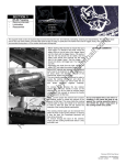
108
ON-THE-CAR
KWIK-LATHE
Instruction Manual and Parts List
Kwik-Way Products Inc.
Copyright 2005. All Rights Reserved
500 5 7th Street, Marion, IA 52302 USA
800-553-5953
Equipment specifications, options and accessories subject to change without notice
521 WARRANTY
Brake Lathes · Tire Changers ·
Wheel Balancers
Kwik-Way Products Inc. (Kwik-Way) provides a limited 521 Warranty on products when purchased in a new and
unused condition to be free from defective material or workmanship from date of purchase as per the following:
Product BENCH MODEL
ON-CAR-LATHES
Category
LATHES
Cast iron
components,
excluding guide rods
PASSENGER CAR
TIRE CHANGERS
WHEEL
BALANCERS
TRUCK LATHES
AND
TIRE CHANGERS
Transmission
Frame, welding
construction
N/A
All other mechanical
parts
N/A
Motor, electrical
components and
labor
Machine, components
and labor
5 Years
Spindle, spindle
bearing and housing
2 Years
All other mechanical All other mechanical All other mechanical
parts
parts
parts
1 Year
Motor, electrical
components and
labor
Motor, electrical
components and
labor
Motor, electrical
components and
labor
Kwik-Way will repair and/or replace, free of charge (FOB factory) all such defective parts, only when
returned to factory with shipping charges prepaid. This warranty does not cover parts and supplies (nylon
inserts, nylon mount-demount heads, breaker blade covers, and mount-demount covers) consumed in
normal operation of the machine.
Kwik-Way disclaims all other warranties, expressed or implied, as to the quality of any goods, including
implied warranties of MERCHANTABILITY and FITNESS FOR PARTICULAR PURPOSES. UNDER NO
CIRCUMSTANCES WHATSOEVER, SHALL Kwik-Way BE LIABLE FOR ANY INCIDENTAL OR
CONSEQUENTIAL DAMAGES, WHETHER BASED ON LOST GOODWILL, LOST RESALE PROFITS,
WORK STOPPAGE, IMPAIRMENT OF OTHER GOODS OR ARISING OUT OF BREACH OF ANY
EXPRESS OR IMPLIED WARRANTY, BREACH OF CONTRACT, NEGLIGENCE OR OTHERWISE,
EXCEPT ONLY IN THE CASE OF PERSONAL INJURY.
Because of Kwik-Way’s constant program of product improvement, specifications are subject to change
without notice.
This warranty does not apply to a product that has been purchased in used condition, that has failed due
to improper installation, repairs, service or that has sustained damage caused by accident, improper use
or shipment.
Model #:
Serial #:
Purchase Date:
For further information or questions, please contact Kwik-Way Products Inc. at 800/553-5953 or 319/3779421, fax 319/377-9101, email [email protected]
Kwik-Way Products Inc.
Copyright 2005. All Rights Reserved
50
0 5 7th Street, Marion, IA 52302 USA
800-553-5953
Equipment specifications, options and accessories subject to change without notice
XW_ vuT{olTjhyTsh{ol
RECEIVING SHIPMENT
Upon taking delivery of your machine, carefully inspect the assembly before removing
the crating and packing materials.
If evidence of damage exists, contact the shipper and Kwik-Way Products Inc.
immediately. Although Kwik-Way Products Inc. is not responsible for damage incurred
during transit, you will be provided assistance in preparation and filing of any necessary
claims.
CAREFULLY READ THIS MANUAL BEFORE ATTEMPTING TO SETUP OR
OPERATE THIS MACHINE.
IMPORTANT NOTE
Always have your serial number ready when communicating with Kwik-Way Products
Inc. regarding parts or service.
Keep this manual in a safe place.
Date Received:
Serial Number:
(Serial Number location: Upper left corner at rear of unit)
Kwik-Way Products Inc.
Copyright 2005. All Rights Reserved
50
0 5 7th Street, Marion, IA 52302 USA
800-553-5953
Equipment specifications, options and accessories subject to change without notice
1
XW_ vuT{olTjhyTsh{ol
SAFETY FIRST
This manual has been prepared for the owner and those responsible for the maintenance of this
machine. It’s purpose aside from proper maintenance and operations, is to promote safety
through the use of accepted practice.
READ THE SAFETY AND OPERATING
INSTRUCTIONS THOROUGHLY BEFORE OPERATING THE MACHINE.
In order to obtain maximum life and efficiency from your machine, follow all the instructions in
the operating manuals carefully.
The specifications put forth in this manual were in effect at the time of publication. However,
owing to Kwik-Way Products Inc. policy of continuous improvement, changes to these
specifications may be made at any time without obligation.
Kwik-Way Products Inc.
Copyright 2005. All Rights Reserved
50
0 5 7th Street, Marion, IA 52302 USA
800-553-5953
Equipment specifications, options and accessories subject to change without notice
2
XW_ vuT{olTjhyTsh{ol
SAFETY INSTRUCTIONS
1. Read, understand and follow the safety and operating instructions found in this manual.
Know the limitations and hazards associated with operating the machine.
2. Eye Safety: Wear an approved safety face shield, goggles or safety glasses to protect eyes
when operating the machine.
3. Grounding the Machine: Machines equipped with three prong grounding plugs are so equipped
for your protection against shock hazards and should be plugged directly into a properly
grounded three-prong receptacle in accordance with national electrical codes and local codes
and ordinances. A grounding adapter may be used. If one is used, the green lead should be
securely connected to a suitable electrical ground such as a ground wire system. Do not cut off
the grounding prong or use an adapter with the grounding prong removed.
4. Work Area: Keep the floor around the machine clean and free of tools, tooling, stock scrap and
other foreign material and oil, grease or coolant to minimize the danger of tripping or slipping.
Kwik-Way recommends the use of anti-skid floor strips on the floor area where the operator
normally stands and that each machine's work area be marked off. Make certain the work area
is well lighted and ventilated. Provide for adequate workspace around the machine.
5. Guards: Keep all machine guards in place at all times when machine is in use.
6. Do Not Overreach: Maintain a balanced stance and keep your body under control at all times.
7. Hand Safety: NEVER wear gloves while operating this machine.
8. Machine Capacity: Do not attempt to use the machine beyond its stated capacity or operations.
This type of use will reduce the productive life of the machine and could cause the breakage of
parts, which could result in personal injury.
9. Avoid Accidental Starting: Make certain the main switch is in the OFF position before connecting
power to the machine.
10. Careless Acts: Give the work you are doing your undivided attention. Looking around, carrying
on a conversation and horseplay are careless acts that can result in serious injury.
11. Job Completion: If the operation is complete, the machine should be emptied and the work area
cleaned.
12. Disconnect All Power and Air to Machine before performing any service or maintenance.
13. Replacement Parts: Use only Kwik-Way replacement parts and accessories; otherwise,
warranty will be null and void.
14. Misuse: Do not use the machine for other than its intended use. If used for other purposes,
Kwik-Way Products Inc. disclaims any real or implied warranty and holds itself harmless for any
injury or loss that may result from such use.
Kwik-Way Products Inc.
Copyright 2005. All Rights Reserved
50
0 5 7th Street, Marion, IA 52302 USA
800-553-5953
Equipment specifications, options and accessories subject to change without notice
3
XW_ vuT{olTjhyTsh{ol
WARNINGS AND CAUTIONS
WARNINGS:
Warning:
Always use OSHA approved protective eye covering during the disc turning
operation.
Warning: Keep the rotor secure on the hub, reinstall and tighten all lugs. Install stud guard
over the studs or lug nuts to prevent loose clothing from catching on them.
Warning: Use a hoist or car stands to support the vehicle while turning rotors. Do not use a
bumper jack or any temporary means to support the vehicle.
Warning: Caliper mounting surface must be free of rust and/or scale for accurate mounting of
the links or KWIK-ADAPTERS.
Warning: When starting the car to turn the rotor, keep feet off the brake. Depressing the
pedal could cause damage to the disconnected caliper.
Warning: Keep loose clothing, fingers and body away from spinning rotor. Failure to do so
could result in Serious Injury.
CAUTIONS
Caution: It is possible to mount the tool bed upside down. Be sure the tool bits are in the up
position or the bits and or the rotor will be damaged.
Caution: Be sure the tool bed does not contact any obstruction when in the fully extended
position.
Caution: The vehicle rotor MUST ALWAYS turn toward the top of the tool bits.
Kwik-Way Products Inc.
Copyright 2005. All Rights Reserved
50
0 5 7th Street, Marion, IA 52302 USA
800-553-5953
Equipment specifications, options and accessories subject to change without notice
4
XW_ vuT{olTjhyTsh{ol
SPECIFICATIONS
ROTOR SIZE
MIN. Rotor thickness
MAX. Rotor thickness
MAX. Rotor diameter
0”
1.5” (38mm)
13.5” (343mm)
FEED RATES
.002 Per Revolution
.004 Per Revolution
.006 Per Revolution
SHIPPING WEIGHT
35 lbs. (15.9 Kg)
38 lbs. W/power feed (17.3 Kg)
Kwik-Way Products Inc.
Copyright 2005. All Rights Reserved
50
0 5 7th Street, Marion, IA 52302 USA
800-553-5953
Equipment specifications, options and accessories subject to change without notice
5
XW_ vuT{olTjhyTsh{ol
SET-UP AND OPERATING INSTRUCTIONS
HELPFUL HINTS
1. Refer to the appropriate service manual for the minimum rotor thickness specification
BEFORE starting the set-up and turning operation. If any disc is below specification-----REPLACE.
2. Before beginning the turning operation, examine the cutting bits for signs of wear or
damage. If the cutting edge is worn, rotate the bit to the next cutting edge. When all three
edges are worn, replace them with KWIK-WAY inserts Part Number 109-1092-23.
3. Warm up the car in Park or in Neutral before attempting the turning operation. When the
engine is cold, the idle R.P.M. will be too high causing premature failure of the tool bits
and poor finish on the rotor. If using the Power Drive, put the car in neutral and attach the
hub driver.
4. Always use the slowest speed on the power feed unit to obtain the best rotor finish.
5. Before beginning the turning operation, be sure the cutting inserts are not in contact with
the raised center portion of the hub.
6. For ease of installation and alignment, tool holder assembly may be removed from the
lathe and reinstalled after the lathe has been attached to the caliper mount adapters.
Kwik-Way Products Inc.
Copyright 2005. All Rights Reserved
50
0 5 7th Street, Marion, IA 52302 USA
800-553-5953
Equipment specifications, options and accessories subject to change without notice
6
XW_ vuT{olTjhyTsh{ol
FOR ALL HONDA AND ACURA CARS
1. Before beginning the turning operation, install the lug nuts to hold the disc in place. The
closed end lug nuts used on some models will bottom-out and not hold the disc securely
enough.
Use a flat washer along with this type of lug nut or use a conventional open end lug nut.
Torque the lug nuts to the appropriate specification indicated in the service manual.
2. Remove the caliper assembly and use the S-hook provided with the Kwik-Lathe to secure
the caliper to the shock tower or spring. Be careful not to kink the brake hose, or to use it
to support the caliper.
3. Measure the caliper thickness; refer to your service manual for the correct procedure.
4. Attach a tie down to the rotor lug on the opposite side to prevent the rotor from turning.
[refer to training bulletin BK-01 for details.]
NOTE: On Prelude ATTS do not use a tie down on the opposite side. Both wheels
must turn during the rotor resurfacing.
5.
Install the Honda Speed Mounting Kit Part Number108-0060-00 as described in the
instruction sheet.
6. Install the vibration damper to the rotor to minimize chattering and produce the best finish.
7. Attach the brake lathe frame to the speed mount, then bolt the tool holder assembly to the
frame making sure to center tool holder to the rotor.
HELPFUL HINT:
For easy attachment and to prevent damage to the cutting bits, remove the tool holder from
the brake lathe before mounting the lathe.
REFER TO THE MAIN TEXT FOR TURNING OPERATION
Kwik-Way Products Inc.
Copyright 2005. All Rights Reserved
50
0 5 7th Street, Marion, IA 52302 USA
800-553-5953
Equipment specifications, options and accessories subject to change without notice
7
XW_ vuT{olTjhyTsh{ol
ATTACHING THE POWERFEED
1. Remove the two 1/4” X 20 hex head bolts located on the handwheel end of the frame.
2. Use these bolts to attach the support hinge provided with the power feed. The pivot bolt
hole should be down and positioned away from the frame.
Kwik-Way Products Inc.
Copyright 2005. All Rights Reserved
50
0 5 7th Street, Marion, IA 52302 USA
800-553-5953
Equipment specifications, options and accessories subject to change without notice
8
XW_ vuT{olTjhyTsh{ol
ATTACHING THE POWERFEED (continued)
3. Using the 1/4" X 3” pivot bolt, attach the power feed to hinge plate.
4. Install the V-belt by first slipping the belt over the hand wheel. While holding the power
feed in against the Kwik-Lathe, position the belt over the two middle pulley grooves.
Kwik-Way Products Inc.
Copyright 2005. All Rights Reserved
50
0 5 7th Street, Marion, IA 52302 USA
800-553-5953
Equipment specifications, options and accessories subject to change without notice
9
XW_ vuT{olTjhyTsh{ol
SET-UP ON CAR
1. Raise the vehicle and support on stands or lift.
WARNING: Follow the vehicle manufacturers requirements on safe and proper lifting
procedures.
2. Remove tire and wheel then lock opposite wheel to keep it from rotating.
3. Use the wire S-hook provided to secure the caliper to the spring or shock tower.
CAUTION: Do not use the brake hose to support the caliper. Do not kink the brake hose.
Kwik-Way Products Inc.
Copyright 2005. All Rights Reserved
50
0 5 7th Street, Marion, IA 52302 USA
800-553-5953
Equipment specifications, options and accessories subject to change without notice
10
XW_ vuT{olTjhyTsh{ol
SET-UP ON CAR (continued)
4. Install the lug nuts to hold the rotor in place, torque to factory recommended
specifications.
5. Install the stud guard over the studs or lug nuts.
WARNING: This is a safety precaution to prevent articles of clothing etc.from being caught in
the rotating rotor or hub.
6. It is always a good machine practice to measure the rotor thickness. Refer to the shop
manual for correct procedure and specifications.
Kwik-Way Products Inc.
Copyright 2005. All Rights Reserved
50
0 5 7th Street, Marion, IA 52302 USA
800-553-5953
Equipment specifications, options and accessories subject to change without notice
11
XW_ vuT{olTjhyTsh{ol
SET-UP ON CAR (continued)
7. Scrape or wire brush the caliper mounting surface clean.
WARNING: Caliper mounting surfaces MUST be free of rust or scale for accurate mounting.
8. Using the scale provided with the Kwik-Mount, position the split side on the caliper
mounting surface with the numerical scale crossing the rotor radius. Read the scale for
the number closest to the rotor center. This number represents the spacer thickness
needed to mount the links.
9. Attach the pointer to the Kwik-Mount handle. Place the mounting handle on the link
studs. With the mounting links loose, move the Kwik-Mount handle until the pointer is on
rotor centerline, tighten the links. This positions the cutter bits correctly and insures a
good surface finish.
Kwik-Way Products Inc.
Copyright 2005. All Rights Reserved
50
0 5 7th Street, Marion, IA 52302 USA
800-553-5953
Equipment specifications, options and accessories subject to change without notice
12
XW_ vuT{olTjhyTsh{ol
SET-UP ON CAR (continued)
10. Install the silencer band. Use the retainer clips to assist in the installation, then remove
the clips before turning the rotor.
11. Install the frame with Power Feed attached to the mounting links. Tighten fasteners.
12. Install the bed being sure that the top of the tool bits are into the direction of rotor rotation.
Kwik-Way Products Inc.
Copyright 2005. All Rights Reserved
50
0 5 7th Street, Marion, IA 52302 USA
800-553-5953
Equipment specifications, options and accessories subject to change without notice
13
XW_ vuT{olTjhyTsh{ol
SET-UP ON CAR (continued)
13. Turn the hand wheel and move the tool bits into the center of the rotor surface. Turn the
rotor by hand in the direction it will be running during the machining operation
Now lock the tool holders with bolt on top of the bed. Note: Control knobs should have a
slight drag. Turn each feed control knob carefully until the tool bit scratches the rotor surface.
Do not back control knobs out.
14. Turn the hand wheel in until BOTH tool bits clear the inside of the rotor surface.
Kwik-Way Products Inc.
Copyright 2005. All Rights Reserved
50
0 5 7th Street, Marion, IA 52302 USA
800-553-5953
Equipment specifications, options and accessories subject to change without notice
14
XW_ vuT{olTjhyTsh{ol
SET-UP ON CAR (continued)
WARNING: -When cutting rotors with raised center hubs, make sure the cutting bits do not
rub against the hub. Turn each feed control knob four lines, this is approximately .008.
DO NOT take heavy cuts, keep cuts to .008 or less.
15. Lock the tool holders in place by gently tightening the bolt on the top of the tool bed.
16. Position the drive belt in the smallest pulley groove on the power feed motor and the
largest pulley groove on the hand wheel. This will give the slowest feed rate and the best
possible surface finish.
Kwik-Way Products Inc.
Copyright 2005. All Rights Reserved
50
0 5 7th Street, Marion, IA 52302 USA
800-553-5953
Equipment specifications, options and accessories subject to change without notice
15
XW_ vuT{olTjhyTsh{ol
TURNING THE ROTOR
1. With the transmission in neutral or park, start the engine and warm up the vehicle until the
idle is at service manual specifications. Keep foot off the brake pedal!
NOTE: -If a Power Drive (Part Number 108-0004-02) is used for this operation, refer to
the Power Drive operating manual for proper procedures.
2. Vehicles with manual or automatic transmissions should be placed in 1st gear unless
directed otherwise by the vehicle service manual.
3. Turn the power feed motor on and snap it in place. There should now be tension on the
drive belt and the hand wheel should be rotating.
4. Allow the Kwik-Lathe to feed out until the tool bits are off the rotor surface. Switch the
power feed off, shut the engine off, and now examine the rotor. If the surface is smooth
and satisfactory, repeat the operation on the opposite side. If the surface is not
satisfactory, then feed the tool bits back to the inside diameter of the rotor and repeat the
turning operation. DO NOT TURN ROTORS BELOW MINIMUM THICKNESS.
CAUTION: Do not put the transmission into park until the engine is off the wheels have
stopped turning. Do not step on the brake.
Kwik-Way Products Inc.
Copyright 2005. All Rights Reserved
50
0 5 7th Street, Marion, IA 52302 USA
800-553-5953
Equipment specifications, options and accessories subject to change without notice
16
XW_ vuT{olTjhyTsh{ol
HELPFUL HINTS
¾
¾
Use a vacuum to clean up the dust and chips, do not use compressed air.
Clean the rotor with soapy water or brake cleaner and wipe with a clean
cloth to remove any particles.
A good rotor finish will be smooth and constant with no chatter marks or grooves.
To ensure proper operation and performance, always insist on Original Kwik-Way
Parts and Supplies.
OPERATING SUPPLIES
000-0070-64
109-1092-23
108-1060-00
108-1061-00
Drive Belt for Power Feed
Carbide Inserts [pkg.10]
Silencing Band [solid rotor]
Silencing Band [vented rotor]
OPTIONAL KWIK-MOUNT KITS
SEE PAGES 20-24
Kwik-Way Products Inc.
Copyright 2005. All Rights Reserved
50
0 5 7th Street, Marion, IA 52302 USA
800-553-5953
Equipment specifications, options and accessories subject to change without notice
17
XW_ vuT{olTjhyTsh{ol
KWIK-LATHE ASSEMBLY
Kwik-Way Products Inc.
Copyright 2005. All Rights Reserved
50
0 5 7th Street, Marion, IA 52302 USA
800-553-5953
Equipment specifications, options and accessories subject to change without notice
18
XW_ vuT{olTjhyTsh{ol
1.
2.
3.
4.
5.
6.
7.
8.
9.
10.
11.
12.
13.
14.
15.
16.
17.
18.
19.
20.
21.
22.
23.
24.
25.
26.
27.
28.
29.
30.
31.
32.
33.
34.
35.
36.
37.
37.
38.
38.
39.
40.
41.
Part Number
000-0102-00
000-0166-32
000-0104-21
000-0591-88
000-0485-26
000-1045-15
000-1150-54
000-1183-11
000-1452-03
000-1150-37
000-1842-09
000-0104-29
000-0540-70
000-1183-20
108-1002-06
000-6606-04
000-6608-25
102-1010-00
108-1003-50
108-1003-40
000-6613-41
108-1000-90
000-1242-22
108-1004-19
108-1005-67
108-1020-50
108-1092-62
108-1006-90
108-1007-02
108-1008-00
110-1008-33
108-1209-08
108-1018-14
000-0495-14
108-1101-00
108-1100-00
108-1082-07
108-1082-10
108-1081-00
108-1081-10
000-0595-01
000-7106-44
000-7000-45
KWIK-LATHE PARTS LIST
Description
¼-20x3/4 Hex Head Cap Screw
¼-20x1-1/4 Socket Head Cap Screw
5/16-18x1-1/4 Hex Head Cap Screw
3/8-16x1-3/4 Socket Button Head
¼-20x3/8 Socket Point Set Screw
3/8-16 Hex Jam Nut-Z.P.
5/16 SAE Washer-Z.P. GR 8
Thrust Washer ½ I.D. x 15/16 O.D.
Collar ½ I.D.
5/16 Wrought Iron Washer
Tension Spring
5/16-18x2-1/4 Hex Head Cap Screw
5/16-18x1/4 Oval Point Set Screw
Curved Washer
Support Plate
Kwik-Lathe Nameplate
Decal-4” Handwheel
Feedscrew-Toolholder
Tool Holder Assembly-Right 6.38 lg.
Tool Holder Assembly-Right 6.38 lg.
Feed Decal
Rod Support
Clip
Frame Plate
Left Frame
Marker Plate
Tool Holder Clamp
Guide Rod
Feedscrew
Guide
Size Control Knob
Handwheel/Pulley Assembly
Tool Holder Plate
½-20x1/2 Cup Point Set Screw
Insert Tool Holder-Right Hand
Insert Tool Holder-Left Hand
Link, Support-2.56 lg.
Link, Support-3.25 lg
Link, Support, Slotted 2.56 lg
Link, Support, Slotted 3.25 lg
10-24 x 3/8 button Head CS
Spring Dowel (grooved)
¼x3/4” Dowel
Kwik-Way Products Inc.
Copyright 2005. All Rights Reserved
50
0 5 7th Street, Marion, IA 52302 USA
Req’d
6
4
4
4
1
2
2
2
1
2
1
1
2
1
1
1
1
1
1
1
1
2
1
1
1
1
1
2
1
1
2
1
1
2
1
1
1
1
1
1
1
2
2
800-553-5953
Equipment specifications, options and accessories subject to change without notice
19
XW_ vuT{olTjhyTsh{ol
STANDARD LINK ADAPTER
Kwik-Way Products Inc.
Copyright 2005. All Rights Reserved
50
0 5 7th Street, Marion, IA 52302 USA
800-553-5953
Equipment specifications, options and accessories subject to change without notice
20
XW_ vuT{olTjhyTsh{ol
OPTIONAL KWIK-WEDGE ADAPTER
FORD F-150, AEROSTAR AND RANGER #108-0200-00
Kwik-Way Products Inc.
Copyright 2005. All Rights Reserved
50
0 5 7th Street, Marion, IA 52302 USA
800-553-5953
Equipment specifications, options and accessories subject to change without notice
21
XW_ vuT{olTjhyTsh{ol
OPTIONAL HONDA/ACURA ADAPTER KIT
#108-0060-00
Kwik-Way Products Inc.
Copyright 2005. All Rights Reserved
50
0 5 7th Street, Marion, IA 52302 USA
800-553-5953
Equipment specifications, options and accessories subject to change without notice
22
XW_ vuT{olTjhyTsh{ol
OPTIONAL HONDA PASSPORT/ISUZU RODEO
REAR ADAPTER #108-1025-50
Kwik-Way Products Inc.
Copyright 2005. All Rights Reserved
50
0 5 7th Street, Marion, IA 52302 USA
800-553-5953
Equipment specifications, options and accessories subject to change without notice
23
XW_ vuT{olTjhyTsh{ol
OPTIONAL FORD, DODGE, 4-WHEEL DRIVE/VAN KIT
#108-0121-09
OTHER OPTIONS AVAILABLE BUT NOT SHOWN:
Composite Rotor Clamp Kit [GM, Ford, Jeep]
Kwik-Way Products Inc.
Copyright 2005. All Rights Reserved
50
0 5 7th Street, Marion, IA 52302 USA
#108-1066-00
800-553-5953
Equipment specifications, options and accessories subject to change without notice
24
XW_ vuT{olTjhyTsh{ol
TROUBLESHOOTING GUIDE
CONDITIONS
1. Poor Rotor Finish
1. Premature deterioration of carbide
insert cutting point
Kwik-Way Products Inc.
Copyright 2005. All Rights Reserved
50
0 5 7th Street, Marion, IA 52302 USA
POSSIBLE CAUSE
1. Loose or worn wheel bearings-replace before
attempting to return rotors
2. Vibration dampener not used
3. Rotor rotation direction incorrect-See Step 12
4. Not on centerline of rotor hub
5. Burrs or dirt under carbide inserts
6. Taking cuts greater than .008 (See Step 14)
7. Burrs on bottom of tool bit
8. Frames out of square (See Illustration below)
9. Nicks or burrs on bottom of slot for tool bit
(Tool bit must lock down on flat surface)
10. Nicks or burrs where tool holder locks down
11. Feed too fast-with Power Feed
12. Rotor RPM too fast-engine not off of fast idle
or idle too fast.
1. Rotor RPM too fast-engine not off of fast idle
or idle too fast
800-553-5953
Equipment specifications, options and accessories subject to change without notice
25
Kwik-Way Products Inc.
th
500 57 St., Marion, IA 52302 USA
319/377-9421
319/377-9101 (FAX)
800/553-5953
www.kwik-way.com
[email protected]