1
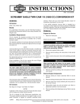
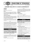
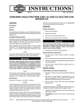
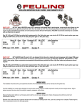
-J05544
REV. 2013-12-06
STREET PERFORMANCE BIG BORE STAGE IV KIT - 103 CUBIC
INCHES
the label on the right side of the frame directly beneath the VIN
sticker. This label is not required outside the state of California.
GENERAL
Kit Number
This conversion kit is intended for High Performance applications only. This engine related performance part is legal for
sale or use in California on pollution controlled motor vehicles.
92500011
Models
For model fitment information, see the P&A Retail Catalog or
the Parts and Accessories section of www.harley-davidson.com
(English only).
Additional Parts Required
This kit is intended for vehicles that are 103 CI displacement
with a stock 3.875 inch bore. If the cylinders are damaged or
worn, replace the cylinder assemblies (Part No. 16547-99A, 2
required).
This kit also requires the separate purchase of the Cam Drive
Retention Kit (25566-06) and Cam Service Kit (17045-99D)
which are available from a Harley-Davidson dealer.
Engine related performance parts are intended for the experienced rider only.
REMOVAL
Prepare for Service
1.
NOTE
If vehicle is equipped with Harley-Davidson Smart Security
System, see Owner's Manual for instructions to disarm the
system.
2.
Separate purchase of Cam Spacer Kit (25928-06) is recommended. This kit contains five different spacers to achieve
proper sprocket alignment.
See appropriate sections in service manual for the special tools
required to install this kit.
Proper installation of this kit also requires the use of Digital
Technician™ at a Harley-Davidson dealer.
The rider's safety depends upon the correct installation
of this kit. Use the appropriate service manual procedures.
If the procedure is not within your capabilities or you do
not have the correct tools, have a Harley-Davidson dealer
perform the installation. Improper installation of this kit
could result in death or serious injury. (00333a)
Position motorcycle on a suitable lift.
Remove seat according to the instructions in the owner's
manual.
When servicing the fuel system, do not smoke or allow
open flame or sparks in the vicinity. Gasoline is extremely
flammable and highly explosive, which could result in
death or serious injury. (00330a)
3.
Remove fuel tank according to the instructions in the service manual.
4.
Remove main fuse. Refer to owner's manual for your
motorcycle.
Remove Engine Components
1.
Remove existing air cleaner assembly. Refer to AIR
CLEANER REMOVAL in service manual.
2.
Remove existing exhaust system. Refer to EXHAUST
SYSTEM REMOVAL in service manual.
This instruction sheet references service manual information.
A service manual for your model motorcycle is required for this
installation and is available from a Harley-Davidson dealer.
3.
Disassemble engine top end and camplate assembly.
Refer to appropriate ENGINE sections in service manual.
Kit Contents
4.
Remove existing clutch diaphragm spring. Refer to
CLUTCH REMOVAL in service manual.
NOTE
See Figure 1 to Figure 3, and Table 1 to Table 3.
NOTES
Installation of this kit by an authorized Harley-Davidson dealer
will not impact your limited vehicle warranty.
The Product Information Label contained in this kit is a
requirement of the California Air Resource Board (CARB)
emission regulation for all 2010 - 2012 Touring models. Place
-J05544
INSTALLATION
Install Engine and Clutch Components
1.
See Figure 3. Inspect camshaft needle bearings (7) and
replace if necessary.
2.
See Figure 1 through Figure 3. Assemble cams to
camplate, performance cylinder heads and engine top end
Many Harley-Davidson® Parts & Accessories are made of plastics and metals which can be recycled.
Please dispose of materials responsibly.
1 of 5
using parts from kit. Refer to appropriate ENGINE sections
in service manual.
3.
Assemble throttle body from kit using original equipment
injectors, fuel line, and fuel rail. Refer to instructions in the
supplied throttle body kit.
4.
Install throttle body assembly to engine using intake
flanges and seals supplied in the throttle body kit. Refer
to instructions from the supplied throttle body kit.
5.
Install clutch diaphragm spring from kit. Refer to CLUTCH
INSTALLATION in service manual.
6.
Install exhaust system. Refer to EXHAUST SYSTEM
INSTALLATION in service manual.
7.
Install air cleaner assembly. Refer to AIR CLEANER
INSTALLATION in service manual.
Final Assembly
1.
2.
3.
Install main fuse. Refer to owner's manual for your
motorcycle.
After installing seat, pull upward on seat to be sure it is
locked in position. While riding, a loose seat can shift
causing loss of control, which could result in death or
serious injury. (00070b)
You must recalibrate the ECM when installing this kit.
Failure to properly recalibrate the ECM can result in severe
engine damage. (00399b)
Installation of this kit requires a calibration update using
Digital Technician. Failure to download calibration update
before starting motorcycle will result in ACR failure.
(00567b)
4.
Start and run engine. Repeat several times to verify proper
operation.
Install fuel tank according to the instructions in the service
manual.
Operation
Install seat according to the instructions in the owner's
manual.
Refer to BREAK-IN RIDING RULES in the Owner's Manual for
instructions to break-in the motorcycle.
-J05544
2 of 5
SERVICE PARTS
is03918j
10
8
9
6
3
1
5
2
4
5
7
Figure 1. Service Parts: Screamin' Eagle TC 103 (1690 cc) Stage 4 Kit
Table 1. Service Parts Table: Screamin' Eagle TC 103 (1690 cc) Stage 4 Kit
Item
Description (Quantity)
Part Number
Item
Description (Quantity)
Part Number
1
3.875 cylinder assembly (black) (2) Sold Separately
7
O-ring, cylinder base
11256
2
Piston (2)
Not Sold Separately
8
Cylinder head assembly, front
(black)
16500014A
3
Piston ring set (2)
22457-10
9
Cylinder head assembly, rear
(black)
16500015A
4
Piston pin (2)
22455-03
10
Automatic compression release
(ACR) plug
16648-08A
5
Piston pin circlip (4)
22097-99
6
Gasket, cylinder head (2)
16787-99A
-J05544
Notes: Piston Kit (22144-08B) includes items 2 through 5. For
cylinder head assembly (8, 9) components, refer to instruction
sheet J05340.
3 of 5
is03589c
2
8
6
10
9
4
7
8
5
3
1
13
Figure 2. Service Parts: Screamin' Eagle TC 103 (1690 cc) Stage 4 Kit
Table 2. Service Parts: Screamin' Eagle TC 103 cubic inch (1690 cc) Stage 4 Kit
Item
Description (Quantity)
Part Number
Item
Description (Quantity)
Part Number
1
Gasket, rocker cover base (2)
16719-99A
9
Breather assembly (2)
17025-03A
2
Gasket, rocker cover top (2)
17386-99A
10
Baffle assembly (2)
26500002
3
Gasket, tappet cover (2)
18635-99B
11
Seal, EFI intake (2) (Not Shown) 29995-86B
4
O-ring, middle push rod cover (4) 11132A
12
Seal, map sensor (2) (Not Shown) 11291
5
O-ring, lower push rod cover (4)
13
Perfect fit pushrods kit
6
O-ring, upper push rod cover (4) 11293
7
O-ring, rocker arm support (2)
11270
8
Breather bolt (4)
4400
-J05544
11145A
18400-03
Notes: Breather assembly 17025-03A includes 8 through 10.
Items 1 through 11 are included in Upper End Overhaul Kit
(17052-99C) and items 6 and 7, Figure 1.
4 of 5
is05094a
9
7
6
8
7
5
2
3
4
2
1
3
Figure 3. Service Parts: Screamin' Eagle Pro 103 (1690 cc) Stage 4 Kit
Table 3. Service Parts: Screamin' Eagle TC 103 (1690 cc) Stage 4 Kit
Item
Description (Quantity)
Part Number
1
Gasket, cam cover
25244-99A
2
Washer
Not Sold Separately
3
Capscrew, flanged
Not Sold Separately
4
Retaining ring
11461
5
Camshaft, front, SE-259E
Not Sold Separately
6
Camshaft, rear, SE-259E
Not Sold Separately
7
Bearing, needle (2) (must be purchased separately, if needed)
9215
8
O-ring, oil pump to cam plate
11293
9
O-ring, cam plate to crankcase (2)
11301
10 58 mm ETC throttle body kit (not shown)
27713-08
11 Clutch diaphragm spring (not shown)
37951-98
Notes: Cam Drive Retention Kit (25566-06) includes 2 and 3. Items 1, 4, 8 and 9 are included in Cam Service Gasket Kit (1704599D). Items 5 and 6 available in Cam Kit (25482-10).
-J05544
5 of 5