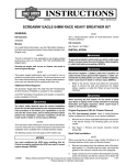
1
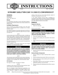
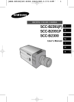
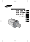
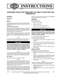
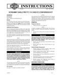
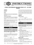
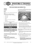
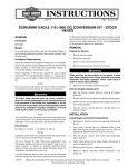
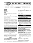
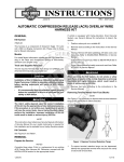
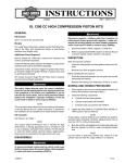
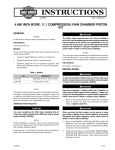
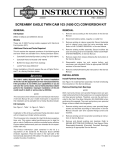
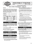
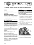
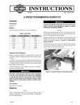
-J04961
REV. 2013-07-22
SCREAMIN' EAGLE TWIN CAM 110 (1800 CC) CONVERSION KIT
GENERAL
REMOVAL
Kit Number
Prepare for Service
27501-10A, 27504-10A
1.
Models
NOTE
If vehicle is equipped with Harley-Davidson Smart Security
System, see owner's manual for instructions to disarm.
For model fitment information, see the P&A Retail Catalog or
the Parts and Accessories section of www.harley-davidson.com
(English only).
Position motorcycle on a suitable lift.
Additional Parts Required
This kit requires the separate purchase of the Cam Drive
Retention Kit (25566-06) which is available from a HarleyDavidson dealer.
The separate purchase of Crankcase Boring Tool Kit (9441906) is recommended for installing this high performance engine
conversion kit.
NOTE
Crankcase Boring Tool Kit (94419-06) includes a modified top
center screw (1093) to verify the crankcase boring tool does
not get damaged when installing the conversion kit. This screw
can also be purchased separately from a Harley-Davidson
dealer for those who wish to use their own boring fixture.
See appropriate sections in service manual for the special tools
required to install this kit.
Proper installation of this kit also requires the use of Digital
Technician™ at a Harley-Davidson dealer.
To prevent accidental vehicle start-up, which could cause
death or serious injury, disconnect negative (-) battery
cable before proceeding. (00048a)
2.
Disconnect battery cables, negative (-) battery cable first.
3.
Remove seat according to the instructions in the service
manual.
4.
Refer to service manual to remove left saddlebag and side
cover.
When servicing the fuel system, do not smoke or allow
open flame or sparks in the vicinity. Gasoline is extremely
flammable and highly explosive, which could result in
death or serious injury. (00330a)
5.
Remove fuel tank according to the instructions in the service manual.
Remove Engine Components
The rider's safety depends upon the correct installation
of this kit. Use the appropriate service manual procedures.
If the procedure is not within your capabilities or you do
not have the correct tools, have a Harley-Davidson dealer
perform the installation. Improper installation of this kit
could result in death or serious injury. (00333a)
NOTE
This instruction sheet references service manual information.
A service manual for your model motorcycle is required for this
installation and is available from a Harley-Davidson dealer.
1.
Remove existing air cleaner assembly. Refer to service
manual.
2.
Remove existing exhaust system. Refer to service manual.
3.
Remove engine from chassis following the instructions in
the service manual.
4.
Disassemble engine top end and bottom end. Refer to
appropriate sections in service manual.
5.
Remove existing clutch diaphragm spring. Refer to service
manual.
MACHINE CRANKCASE
Kit Contents
See Figure 4 to Figure 7 and Table 2 to Table 5.
NOTES
Installation of this kit by an authorized Harley-Davidson dealer
will not impact your limited vehicle warranty.
This conversion kit is intended for High Performance applications only. This engine related performance part is legal for
sale or use in California on pollution controlled motor vehicles.
-J04961
The procedures in this instruction sheet should be performed by one experienced in precision measuring techniques. Failure to meet tolerances called for in this
instruction sheet can result in engine damage. (00511b)
Many Harley-Davidson® Parts & Accessories are made of plastics and metals which can be recycled.
Please dispose of materials responsibly.
1 of 7
is03517
3.
Inspect and clean engine case mating surfaces.
4.
See Figure 6. Reassemble engine case with original
screws, except the top center screw between the cylinders,
and tighten to specifications listed in service manual.
NOTE
To prevent damage to crankcase boring tool, it is important to
replace the top center screw with a modified top center screw
(1093). This screw is included in the Crankcase Boring Tool
Kit (94419-06) and can be purchased separately from a HarleyDavidson dealer.
1
5.
2
Install modified top center screw (1093) between the cylinders and tighten to 50-90 in-lbs (5.6-10.2 Nm).
NOTE
To aid in crankcase boring, a Screamin' Eagle Crankcase
Boring Tool Kit (94419-06) is available. Modified top center
screw (1093) is included in this kit. Refer to Harley-Davidson
Genuine Motor Accessories and Genuine Motor Parts catalog
or Screamin' Eagle Pro catalog.
1. O-ring counterbore
2. Spigot bore
6.
Figure 1. Spigot Bore and O-Ring Counterbore Dimensions
See Figure 1 and Table 1. Machine crankcase cylinder
spigot bore and O-ring counterbore to the dimensions
shown.
Modify Crankcase
NOTE
Table 1. Spigot Bore and O-Ring Counterbore Dimensions
Description
Bore
Depth
Spigot Bore
4.205 +/- 0.010 in. 1.625 +/- 0.010 in.
(107 +/- 0.25 mm) (41.3 +/- 0.25 mm)
O-Ring Counterbore
4.415 +/- 0.002 in. 0.085 +/- 0.003 in.
(112 +/- 0.05 mm) (2.16 +/- 0.08 mm)
is03456
To prevent severe engine damage, thoroughly clean and
remove all chips and debris from the engine crankcase after
boring.
1.
Disassemble crankcase and wash (or clean) chips and
debris from engine crankcase halves as necessary.
2.
See Figure 2. Using a 11/32 in. (8.7 mm) drill bit, drill out
the existing threads of the top center screw hole. Drill to
a depth of 0.79 in. (20 mm) from the gasket surface.
3.
Using a size "F" in. (6.6 mm) drill bit, extend the top center
screw hole 1.00 in. (25.4 mm) maximum to a depth of 1.79
in. (45.5 mm) from the gasket surface.
4.
Using a bottoming tap (purchased separately) size 5/1618 UNC-2B, tap the screw hole to a minimum depth of
1.59 in. (40.4 mm) from the gasket surface.
5.
See Figure 2 and Figure 3. Remove the thin material
between the cylinders next to the top center screw as
shown, by using a 5/8 in. (16 mm) ball end mill and milling
a 5/16 in. (7.94 mm) radius at the two points shown.
6.
Refer to the appropriate service manual and assemble
the engine with the following changes:
•
See Figure 6. Install the top center engine crankcase
screw (15) supplied in kit but do not tighten.
•
Tighten all of the engine crankcase screws to the specified
torque, except the top center engine crankcase screw.
Figure 2. Cylinder Wall
Crankcase Boring Preparation
NOTE
During final reassembly of the engine, Harley-Davidson
recommends replacing the Original Equipment cylinder studs
with Screamin' Eagle High Tensile Studs (16505-01).
1.
Remove cylinder studs from the engine crankcase.
2.
Mask off all bearings and oil holes to prevent debris and
contaminants from entering those areas.
-J04961
NOTE
Note that the cylinder spigot seal is a rectangular o-ring which
should be seated at base of cylinder prior to the cylinder
being assembled to the crankcase. Using the crankcase to
seat the rectangular o-ring to the base of the cylinder can roll
2 of 7
(spiral) the o-ring during assembly. A rolled (Spiraled) o-ring
will create a leak path at the cylinder/crankcase interface.
•
1.
After the cylinders and heads have been installed and the
hardware tightened to specification, tighten top center
engine crankcase screw to 50-90 in-lbs (5.6-10.2 Nm)
Connect battery cables, positive cable first.
You must recalibrate the ECM when installing this kit.
Failure to properly recalibrate the ECM can result in severe
engine damage. (00399b)
INSTALLATION
Install Engine and Clutch Components
1.
See Figure 6. Inspect camshaft needle bearings (7) and
replace if necessary.
2.
See Figure 4 through Figure 6. Assemble engine top end
and bottom end using parts from kit. Refer to appropriate
sections in service manual.
3.
Install engine in chassis following the instructions in the
service manual.
4.
Install clutch diaphragm spring from kit. Refer to service
manual.
5.
See Figure 7. Install exhaust head pipe assembly (1) from
kit and mufflers previously removed. Refer to service
manual.
6.
See Figure 4. Install Air Cleaner Kit (29592-05) according
to the instructions in the Instruction Sheet.
Installation of this kit requires a calibration update using
Digital Technician. Failure to download calibration update
before starting motorcycle will result in ACR failure.
(00567b)
2.
Calibrate the ECM before connecting the ACR overlay
harness connectors to the ACR solenoids in the cylinder
heads.
3.
Install fuel tank according to the instructions in the service
manual.
After installing seat, pull upward on seat to be sure it is
locked in position. While riding, a loose seat can shift
causing loss of control, which could result in death or
serious injury. (00070b)
Install ACR Overlay Wire Harness
See Figure 7. Install the ACR Overlay Wire Harness Kit (7062306) according to the instructions in the Installation Sheet.
Final Assembly
Connect positive (+) battery cable first. If positive (+) cable
should contact ground with negative (-) cable connected,
the resulting sparks can cause a battery explosion, which
could result in death or serious injury. (00068a)
4.
Install seat according to the instructions in the service
manual.
5.
Install left side cover and left saddlebag. Refer to service
manual.
6.
Start and run engine. Repeat several times to verify proper
operation.
Operation
Refer to the owner's manual for instructions to break-in the
motorcycle.
is03502a
2
3
4
10 10
5
1
8
6
1.
2.
3.
4.
5.
Tap hole with 5/16-18 UNC-2B bottoming tap
Extend full thread depth - 0.80 in. (20 mm)
Distance - 0.48 in. (12 mm)
Distance - 0.48 in. (12 mm)
Drilled hole diameter - 0.34 in. (8.6 mm)
9
7
6.
7.
8.
9.
10.
Extend hole depth - 1.00 in. (25.4 mm) maximum
Unthreaded screw hole depth - 0.79 in. (20 mm)
Distance to center of crank - 5.90 in. (150 mm)
Distance to center of crank - 6.00 in. (152 mm)
Radius - 0.31 in. (7.94 mm) - use 5/8 in. (16 mm)
ball end mill
Figure 3. Top Center Engine Crankcase Screw Hole Modification
-J04961
3 of 7
SERVICE PARTS
is04669b
10
9
8
6
3
1
5
2
4
5
7
Figure 4. Service Parts: Screamin' Eagle Twin Cam 110 (1800 cc) Conversion Kit
Table 2. Service Parts: Screamin' Eagle Twin Cam 110 (1800 CC) Conversion Kit
Item
1
Description (Quantity)
Part Number
Item
Description (Quantity)
Part Number
Cylinder assembly (Black) (2) 17285-07A
8
Backplate, air cleaner
29764-08A
Cylinder assembly (Silver) (2) 16815-07A
9
Cylinder head, front (black) (w/ACR)
17288-08A
Cylinder head, front (silver) (w/ACR)
17289-08A
Cylinder head, rear (black) (w/ACR)
17252-07A
Cylinder head, rear (silver) (w/ACR)
17262-07A
Automatic Compression Release
(ACR)
28861-07A
2
Piston (2)
Not Sold Separately
3
Piston Ring Set (2)
21951-11
4
Piston pin (2)
22269-07
5
Piston pin circlip (4)
22097-99
6
Gasket, cylinder head (2)
16801-07C
7
O-ring, cylinder spigot (2)
Not Sold Separately
-J04961
10
11
Notes: Piston Kit (21991-11) includes 2 through 5.
Item 5 through 7 are also included in Engine Overhaul Gasket Kit
(17350-07B). Refer to 2010 FLHTCUSE5 Parts Catalog (9942810) for cylinder head assembly (9, 10) components.
4 of 7
is03589c
2
8
6
10
9
4
7
8
5
3
1
13
Figure 5. Service Parts: Screamin' Eagle Pro TC 103 (1690 cc) Stage 3 Upgrade Kit
Table 3. Service Parts: Screamin' Eagle Twin Cam 110 (1800 CC) Conversion Kit
Item
Description (Quantity)
Part Number
Item
Description (Quantity)
Part Number
1
Gasket, rocker cover base (2)
16719-99B
9
Breather assembly (2)
17025-03A
2
Gasket, rocker cover top (2)
17386-99A
10
Baffle assembly (2)
26500002
3
Gasket, tappet cover (2)
18635-99B
11
Seal, EFI intake (2)
26995-86B
4
O-ring, middle push rod cover (4) 11132A
12
Spring, clutch diaphragm (2) (Not 37951-98
Shown)
5
O-ring, lower push rod cover (4)
13
High capacity tappet (4)
6
O-ring, upper push rod cover (4) 11293
7
O-ring, rocker arm support (2)
11270
8
Breather bolt (4)
4400
-J04961
11145A
Not Sold Separately
Notes: Items 1 through 11 are included in Engine Overhaul
Gasket Kit (16500228) Item 13 is included in High Capacity
Tappet Kit (18572-13).
5 of 7
is03590b
15
13
11
14
21
22
9
7
6
10
20
12
22
22
8
16
7
5
3
4
2
3
1
Figure 6. Service Parts: Screamin' Eagle Pro Twin Cam 110 (1800 cc) Conversion Kit
Table 4. Service Parts: Screamin' Eagle Twin Cam 110 (1800 CC) Conversion Kit
Item
Description (Quantity)
Part Number
1
Gasket, cam cover
25244-99A
2
Washer
6294
3
Cam drive retention kit w/6294, screws, and washer
25566-06
4
Retaining ring
11461
5
Camshaft, front
Not Sold Separately
6
Camshaft, rear
Not Sold Separately
7
Bearing, needle (2) (must be purchased separately, if needed)
9215
8
O-ring, oil pump to cam plate
11293
9
O-ring, cam plate to crankcase (2)
11301
10 O-ring, crankcase ring dowel (2)
26432-76A
11 O-ring, piston cooling (2)
11140
-J04961
6 of 7
Table 4. Service Parts: Screamin' Eagle Twin Cam 110 (1800 CC) Conversion Kit
Item
Description (Quantity)
Part Number
12 Retaining ring, internal
35114-02
13 O-ring, crankcase dowel (2)
Not Sold Separately
14 Seal, main bearing oil
12068
15 Screw, top center crankcase, long
1090A
16 O-ring, CPS (not shown)
11289A
17 Seal, exhaust (2) (not shown)
65324-83B
18 Seal, oil interconnect (not shown) (Softail models only)
45359-00
19 Valve seal (4) (not shown) (not required)
18067-09
20 Bearing, main
24605-07
21 Thrust washer
8972
22 Bearing Kit w/8972, 24607-07, 35114-02, and inner race (not shown)
24004-03B
23 Screw, modified, crankcase boring (Not Shown) (must be purchased separately)
1093
Items 5 and 6 are available in Cam Kit (25638-07)
Items 8 through 22 are included in Engine Overhaul Gasket Kit (17350-07B)
Items 13 and 7 (table 2) are available in Seal Kit (11907), which is included in the Engine Overhaul Gasket Kit.
is03616b
1
Figure 7. Service Parts: Screamin' Eagle Twin Cam 110 (1800 cc) Conversion Kit
Table 5. Service Parts: Screamin' Eagle Twin Cam 110 (1800 CC) Conversion Kit
Item
1
Description (Quantity)
ACR Overlay Wire Harness Kit (Refer to Instruction Sheet J04441)
-J04961
Part Number
70623-08
7 of 7