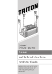
1
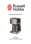
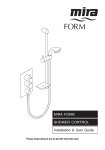
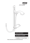
Luda - Luda S
®
UK
®
®
8.5kW AKW Intelligent Shower
WR AS
WRAS
WRAS
WRAS
WRAS
RNIB
*
INSTALLATION
Instructions & Service Manual
(For User Instructions read from back page)
ED
OV CT
APPRDU
PRO
approved
p r o d u c t
UK WATER SUPPLY
REGULATIONS
BBEAB
EA B
Approved
CARE
BEAB
BEA B
EMC Verified
BEA B
Approved
BEA B
INTERTEK
Approved
B
EA B
IP45
EMC Verified
BEAB
CARE
BEEA
AB
B
B
GB and International patents
pending, EU Registered Design
000741558-0001/2/3/4,
International and other Designs
Pending.
*Luda S does not carry RNIB Ref.
®
Read all instructions carefully before installation.
BEA BLeave this
booklet
BE
A B with the end user for future
Approved
reference and servicing.
11-008-058-01
INTERTEK
Contents
Page
Introduction
2
Important Safety Information & Requirements
3-5
Specifications
6
Features & Components 7
Main Components 8
Electrical / Water Requirements 9-12
Positioning of Shower 13
Shower Heater Main Components 14
Installation, Positioning & Fitting To Wall 15-16
Plumbing Installation 17
Water Priming 18
Electrical Installation 19-21
Commissioning 22-25
Fault Finding 26-28
Service Engineer Fault Diagnosis tables
29-32
Service Engineer Maintenance
33-34
Spare Parts / Installation Details / In-Service Tests 35-39
Warranty / Contact Information
8-9
User Care and Maintenance / User Fault Diagnosis 6-7
User Operating Instructions
2-5
INTRODUCTION
Take time to read these instructions thoroughly before starting installation and leave
with the end user for future reference.
Shower installation must be carried out by a suitably qualified person (eg NIC EIC)
and in accordance with these instructions.
This unit is the first BEAB Care shower which can be installed in the sprayhead
splash zone because it has the higher IP45 (water resistance safety rating) and this is
why there are more case screws. All case screws must be fitted.
Take time to complete the installation details and record the commissioning tests for
future reference, see pages 36 & 37.
Page 2
PLEASE READ ALL INSTRUCTIONS CAREFULLY AND IMPORTANT SAFETY INFORMATION BEFORE COMMENCING INSTALLATION
Warning
This product must be used and maintained in good working order in
accordance with these instructions and recommendations.
IMPORTANT: Read all of these instructions. Ensure they are
retained by the user for recording future maintenance or servicing.
This product is only suitable for mains fed COLD WATER.
AUTION
DO NOT take risks with Plumbing or Electrical Installation.
Only competent trades persons should carry out this installation.
DO NOT install or operate shower if the location is liable to freezing.
NSTRUCTIONS
RE INSTALLING
DO NOT operate shower if water has leaked inside the unit before operation.
S PRODUCT
DO NOT remove shower front cover when in operation.
DO NOT operate the shower if water ceases to flow during operation.
DO NOT operate the shower if the spray head or hose is damaged.
DO NOT restrict flow out of the shower by blocking or obstructing spray handset.
The outlet must not be connected to any other parts or fittings other than
EC1 Luda shower handset and Hose or EC2 Luda S shower handset and Hose.
Maintenance may be required before the appliance can be safely used. This is to be
carried out by competent trades persons only. See service engineers section.
There are no user-serviceable components beneath the shower cover.
Only a competent trades person should remove this cover and use genuine AKW
replacement parts. See spare parts section.
Isolate the electrical and water supplies before starting any work and review this
installation guide or contact your installer:
if the shower cover is not correctly fitted and water has entered the case,
if the case or cover is damaged or broken,
if the appliance shows signs of distinct change in performance, strange noises or begins to smell or smoke,
(Refer to “Contact Information” page 9 of the User Instructions and Warranty.)
Page 3
IMPORTANT SAFETY INFORMATION
Caution! Danger of Death 230V AC
Lethal Voltage present on the AC supply.
This Appliance MUST BE EARTHED. Make sure any Supplementary bonding complies with the requirements for electrical installations and Wiring regulations in
accordance with BS 7671.
Make sure mains power is off before installation.
This Appliance is intended to be permanently connected to the live wiring of the electrical mains supply system.
Other electrical equipment must not be connected to the same shower circuit.
This product must be installed by a qualified and competent electrician and in
accordance with the current edition of the Wiring Regulations BS 7671.
Switch off at the isolating switch when not in use.
This is a safety procedure recommended with all electrical appliances.
It is recommended that the shower and installation is checked every two years by a
competent electrician to ensure there is no deterioration due to age or usage.
Plumbing Precautions
The plumbing installation must comply with Water Fitting Regulations,
Building Regulations and should be in accordance with BS 6700.
The optional hose retainer must be used to comply with the Water Fitting Regulations
and prevent water supply contamination Category 5 installations where double check
valves are not installed. Note that both Luda and Luda s have double check valves.
Make sure there is a Cold Water feed near to the installation with a local service
isolation valve.
Chrome Plated or Stainless Steel Supply Pipes.
DO NOT connect the shower unit directly to chrome plated or stainless steel pipe.
NSTRUCTIONS
Standard JG pipe connectors ARE NOT SUITABLE for connecting to CHROME
RE INSTALLING
or STAINLESS PIPEWORK.
AKW Recommend the use of a John Guest chrome pipe adaptor (Part No.25283.
S PRODUCT
Top and Rear Entry only) or an equivalent.
Chrome plating must be completely removed 20mm before insertion into standard JG fittings. Always use the Collet Clips provided.
Flush the supply pipe prior to connecting the shower unit to remove any debris in the
pipework.
DO NOT solder pipes or fittings within 110mm of the shower appliance.
DO NOT fit any form of outlet flow control to the water heater.
DO NOT use excessive force when making connections to the water supply inlet, the
flexible hose or the spray head.
AUTION
Complete all plumbing connections prior to making any electrical connections.
Page 4
IMPORTANT SAFETY INFORMATION
NOTE: The manufacturer’s rigorous quality systems may
require operating the shower with water at the factory. The water shall be removed where possible, however there
may be a small amount of water residue left in the shower.
A sealing pipe is used to prevent any excess water from entering
inside and damaging the unit.
AUTION
It is essential the commissioning procedure is followed carefully to prime the
unit with water prior to switching on.
Failure to carry out this operation will result in damage to the unit and will
NSTRUCTIONS
invalidate the warranty.
RE INSTALLING
S PRODUCT
The shower must not be exposed to freezing conditions.
Make sure pipework is properly insulated.
If the appliance is frozen the warranty will be void.
The unit must be mounted onto the finished wall surface (on top of the tiles).
DO NOT tile up to or around the unit after fixing to wall.
If the shower is installed in areas of hard water (above 200 ppm temporary hardness),
a scale inhibitor may have to be fitted. For advice contact AKW Customer Service,
Refer to “Contact Information” page 9 of the User Instructions and Warranty.
This product is not suitable for fitting in steam rooms.
999991234500
Regularly clean the spray head with descalent, failure to do this may restrict water
flow resulting in higher temperatures, this could also cause operation of the Pressure
Relief Device (PRD).
Luda®- AKW Intelligent Shower ®
INTERTEK
BEA B 230-240V
Approved
BEAB
CARE
50Hz 7.8-8.5kW OUTLET RATED 0MPa(BAR)
SUPPLY INLET: 0.05-1MPa (0.5 - 10 bar) IP45
SAFETY VENT - NEVER BLOCK WATER OUTLET
KEEP SPRAY HEAD HOLES CLEAR AND CLEAN
USE ONLY AKW HOSE AND SPRAY HEAD
Model 29005
230-240V
50Hz 8.1-8.5kW OUTLET RATED 0MPa(BAR)
SUPPLY INLET: 0.05-1MPa (0.5 - 10 bar) IP45
SAFETY VENT - NEVER BLOCK WATER OUTLET
KEEP SPRAY HEAD HOLES CLEAR AND CLEAN
USE ONLY AKW HOSE AND SPRAY HEAD
Model 29006
Locate the product identification label on
the shower casing for completing the installation details on page 36.
S ON LABEL DETAILS:
NOTES ON LABEL DETAILS:
T, SYMBOLS AND LOGO ARE BLACK ON WHITE OR
SILVER
BACKGROUND.
Page
5 AND
1. TEXT, SYMBOLS
LOGO ARE BLACK ON WHITE OR SILVER BA
TER PROOF ADHESIVE SUITABLE FOR BONDING LABEL TO SURFACE.
2. WATER PROOF ADHESIVE SUITABLE FOR BONDING LABEL TO SU
ELECTRICITY SUPPLY
PLUMBING SUPPLY
Specifications
Supply Source
Mains pressure cold water only
Minimum Dynamic Pressure *
50kPa (0.5 Bar)
Maximum Static Pressure
1000 kPa (10 Bar)
Optimal Minimum Dynamic Pressure
100 kPa (1 Bar)
Maximum Inlet Temperature
28°C
Minimum Inlet Temperature
2°C
Inlet Connection
15mm pushfit (John Guest Fitting)
Outlet Connection
1/2” BSP Male thread Fitting
Nominal Rating at 240 V
Supply Fuse / Circuit Breaker
29005-8.5kW
29006-8.5kW
29005-8.5kW 40A
29006-8.5kW 40A
Residual Current Device (RCD)
Continuously Rated
30 mA (must be fitted)
Supply Cable
Refer to current wiring regulations and BS 7671 to determine minimum
cable size. No larger than 16mm2
Isolation Switch (e.g. Pull Cord)
45 Amp Double pole with 3mm
contact separation.
Height 435 mm
Width234mm
Depth110mm
Water Ingress Rating
IP45
Water and Cable Entry Points
Top, bottom or back.
Shower Drain Pump Connections
Suitable for M Series, D4 (Flow Sensor) or AKW A4 (Flow Switch) connections on AKW products only.
* For Optimal Product Performance the recommended minimum dynamic water pressure should be 100kPa (1 Bar).
This Product Complies with the requirements of current British and European safety
standards for household appliances, and has met the following harmonised european
standards in the confirming assessment.
Complies with requirements of the British Electrotechnical Approvals Board (BEAB).
BEAB APPROVED / BEAB CARE / KIWA / RNIB / WRAS / IP45
BS EN 60335-1:2002, BS EN 60335-2-35:2002, BS EN 50366:2003
Page 6
Features & Components
The Intelligent shower has been designed specifically as a thermostatically controlled
‘CARE’ shower to meet the requirements of current British and European safety
standards for household appliances.
This shower has a special water ingress safety standard rating, making this the first
care shower to meet the IP45 (water resistance safety rating) and this why there are
many case screws. All case screws must be fitted.
This shower also has an integral non-return value, so the shower hose does not
need to be retained in anyway.
The Intelligent shower has a large ergonomic touch panel. This has been specifically
designed to allow for easy operation. The large display panel clearly indicates the
level of temperature and flow rate.
Temperature / flow rate
Adjusting the temperature may affect the flow rate.
The maximum flow rate for the given temperature may be greater in Summer than in
Winter due to the warmer mains water supply.
Flow setting
The shower is adjusted in 3 stages- low, medium and high.
Phased Shut down
The power button will flash for around 5 seconds after being pressed as the system
shuts down in an ordered manner and then turns off.
Auto shut down
The shower will automatically shut down after 30 minutes of operation. It can be
restarted immediately.
Safety cut-out
The shower is fitted with an over-temperature safety device.
In the event of abnormal operation which could cause unsafe temperatures within
the unit, the device will disconnect the heating elements.
It will require a visit from a service engineer to determine the nature of the fault and
replace the safety device.
Replacement parts can be ordered from Customer Services. See Spare Parts page 35. For more information refer to “contact information” page 9.
Due to the AKW policy of continuous improvement, this specification may be altered
without prior notice.
Page 7
Main Components & Box Contents Checklist
Check all packaging for screw packs and other parts
Box contents
5
Shower Unit
Shower Spray Head
Shower Hose
Riser Rail
2x Grab Rail 900 Elbow
Grab Rail1800 Elbow
Shelf
Soap Dish
Soap Dish Cover Cap
(use if shelf not fitted)
10. 2x Rail Slider
11.Soap Dish Adapter
Hook
12.Optional Hose Retainer (use if required)
13.Shower Head Wall
Bracket
14. Pump signal wire
Insulating Sleeve
15. 3x Wall Screws
16. 3x Wall Plugs
17. Instructions
18. Registration /
Warranty Card & Envelope.
1.
2.
3.
4.
5.
6.
7.
8.
9.
2
4
1
10
3
6
7
8
9
10
13
11
12
5
14
15
16
17
Page 8
18
Electrical Requirements
Caution
Danger of Death 230V AC
Lethal Voltage present on the AC supply.
WARNING - THIS APPLIANCE MUST BE EARTHED
The installation, supply cable and circuit protection must conform to the current wiring regulations and be sufficient for the amperage required and length of
cable run.
Before making electrical connections within the installation, ensure that the electrical
supply has been isolated.
The shower must be connected to its own independent electrical circuit.
IT MUST NOT be connected to any other ring main, spur, socket outlet, lighting circuit or cooker circuit.
The electrical supply must be adequate for the loading of the unit and existing circuits.
Check your consumer unit (main fuse box) has a main switch rating of 80A or above
and that it has a spare fuse way which will take the miniature circuit breaker (MCB)
necessary for the shower (see schematic of installation circuit).
If your consumer unit has a rating below 80A or if there is no spare fuse way, then the installation may require a new consumer unit serving the house or just the shower.
Contact the local electricity company if in any doubt.
The earth continuity conductor of the installation must be effectively connected electrically, to all exposed metal parts of other appliances and services in the room in
which the shower is to be installed. This must conform to current wiring regulations.
All the applicable exposed metallic parts in the bathroom must be bonded together
using an earth cable of at least 4mm2 cross sectional area, in accordance with the
requirements of the wiring regulations. These parts may include metal baths, radiators,
water pipes, taps and waste fitting.
Page 9
Electrical Requirements
30mA RCD (may be part of consumer unit)
Shower unit
Consumer unit (80A
minimum isolating
switch rating)
45A Double pole isolating
switch (eg Pull cord)
All components must be rated and installed in accordance with wiring regulations.
The appliance must be earthed.
For adequate circuit protection DO NOT use a rewireable fuse. Instead use a
suitably rated miniature circuit breaker or cartridge fuse.
29005
29006
CIRCUIT PROTECTION -
8.5kW 240V AC
MCB 40A
A 30mA residual current device (RCD)
must be installed.
A 45 amp double pole isolating switch with a minimum contact gap of 3mm in both
poles must be incorporated in the circuit.
The isolating switch must have a mechanical indicator showing when the switch is in
the OFF position, and the wiring must be directly connected to the switch.
The isolating switch must be accessible and clearly identifiable, but out of reach of a
person using a fixed bath or shower, except for the cord of a cord operated switch
and should be placed so that it is not possible to touch the switch body while standing in a bath or shower cubicle. It should be readily accessible to switch off after
using the shower.
Where shower cubicles are located in any rooms other than bathrooms, all the socket outlets in those rooms must be protected by a 30mA RCD.
Consult the wiring regulations.
To obtain full advantage of the power provided by the shower, use the shortest cable
route possible from the consumer unit to the shower.
Page 10
WARNING - THIS APPLIANCE MUST BE EARTHED
The current carrying capacity of the cable must be at least that of
the shower circuit protection.
Refer to the current wiring regulations BS 7671 to determine minium cable size.
Do not exceed 16mm maximum cable size for this product.
2
Site conditions must be assessed by a competent electrician to determine correct
cable size and permissible circuit length.
Shower circuit cable separation from other circuits must meet wiring regulations.
It is strongly recommended to use a minimum of 10mm2 cabling throughout the
shower installation.
Note: the electrical insulating sleeve supplied must only be used to insulate
the pump signal wire, shown on page 20.
Failure to install this AKW product in accordance with supplied instructions
or the making of any unauthorised modifications will invalidate any warranty
and will affect product safety.
Page 11
Water Requirements
The installation must be in accordance with Water Regulations and Byelaws.
To ensure activation of the heating elements, the shower must be connected to a
mains cold water supply with a minimum running pressure of 50kPa (0.5 bar) at a
minimum flow rate of nine litres per minute with a maximum static pressure of
1000kPa (10 bar). For Optimal Product Performance the recommended minimum
dynamic water pressure should be 100kPa (1 Bar). Dynamic pressure should not fall
below 50kPa (0.5 bar) when other draw offs are used (e.g. flushing toilet).
Note: An Isolating stop valve must be provided before connecting to the shower.
We recommend that isolation valves (not supplied) must be fitted as close as is
practicable to the water supply inlets of the shower heater whilst being accessible for
maintenance and servicing purposes.
A typical system layout is shown below. Not to scale.
Mains electric supply must be
isolated with a 45amp double
pole isolating switch.
Mains COLD
water supply
must be isolated
with a stopvalve.
Pipe entry from
either top, offset
rear or bottom.
Mains supply
permanently
connected to
consumer unit.
Consumer unit containing 30mA RDC.
DO NOT use sealing compounds on any pipe fittings for the installation.
Never fit the appliance to the hot water supply.
Note: If the stated flow rates are not available, it may not be possible to achieve optimum performance from the unit throughout the year.
Page 12
Positioning of Shower
WARNING! The shower must not be positioned where it will be subjected to freezing conditions.
FOR EASE OF SERVICING, THE UNIT MUST ALWAYS BE MOUNTED ON THE
FLAT SURFACE OF TILED WALLS. NEVER TILE UP TO THE SHOWER UNIT.
IMPORTANT: The flat surface must cover the full width and length of the back
plate, otherwise difficulty may arise when fitting the cover and subsequent operation
of the unit may be impaired.
Refer to the illustration below for correct positioning of the shower controls and
showerhand set. Position the shower unit vertically.
Check there are no pipes or electrical cables inside the wall before drilling.
Shower unit can be mounted either side of riser rail.
Ensure minimum
side and top
clearance of
120mm.
The height of the controls are dependent
upon the type of installation. For non-dwelling locations refer to Building Regulations Document M diagram 23 (min 750mm, max 1000mm)
and for the shower head (min 1200mm,
max 1400mm.) Further reference may also
be made to BS8300:2009 (non-dwellings)
or DD266:2007 (dwellings).
Alternatively, a height for both as specified
by an Occupational Therapist to suit a
specific user needs may be required.
DO NOT obstruct the back and sides of the shower as this will prevent the
Pressure Relief safety Device from operating.
DO NOT operate the shower with a damaged or kinked shower hose, or a blocked
spray head which can cause the Pressure Relief Device (PRD) to operate.
When commissioning, the spray head must be removed from the flexible hose.
Failure to follow this procedure may cause the PRD to operate.
Ensure the unit is positioned over a bath or shower tray.
If the Pressure Relief Device operates, switch the unit off at the pull-cord and contact
Customer Service for advice on replacing the PRD.
Page 13
Shower Heater Main Components
Top pipe inlet and
cable entry cover
Power Circuit Board
(PCB)
Terminal block
Water heater can
Rear pipe inlet and cable entry
Mounting screw cover
Safety seal cover.
This must be fitted at all
times the unit is powered.
Mounting screw
cover
Filter
5x seal screws
John Guest* Pipe
Connector
Air bleed button
Front
Cover
Mounting screw
cover
Flow valve
DIP
switch
Bottom pipe inlet and
cable entry cover
Ribbon cable
Shower hose outlet
Page 14
Installation Fitting shower to the wall
Ensure that the electrical supply is switched off at the
mains.
Ensure that the water supply is turned off.
Determine
the positioning of the
cable and
water-pipe
Step 1
Installation
Fitting
shower
toentries.
the
Lift off the front coverplate and entry covers.
wallInstallation Fitting shower to the
Disassemble shower to get to the components by removing the front coverplate and
wall the front cover from the main body. Retain all the screws for IP45 rating.
unscrewing
Entry cover
Front coverplate
Front cover
Entry cover
Step 2
Disconnect the ribbon cable from the PCB to separate the front
cover from the shower.
PCB
Remove
Ribbon
cable
Page 15
Installation Positioning
Step 3
CASE PREPARATION
Remove the Safety Seal Cover
(5 screws) and determine the
positioning of the cable and
water-pipe entries.
Turn the John Guest* Inlet
Connector to suit supply
pipe. See step 5.
Remove sealing caps.
Choose the shower location.
Only seal between the pipe and
the wall to prevent water entering the wall for back entry.
Step 4
Remove the 3 fixing
screw sealing caps.
Use the back plate as a template, ensure it is vertical.
Mark the fixing holes ensuring the cable and pipe positions align
with the entry positions on the shower. Drill and insert wall plugs taking care there are no hidden cables or pipes.
FF
+
S1
Route the Sensor cable for the drain pump (if applicable). See page 20.
Use all 3 screw fixing positions.
3X
3x
3X Screw fixing positions
Caution! Do not drill into
cables or pipes.
Page 16
Important! Replace the 3 fixing
screw sealing caps.
Installation Step 5
Plumbing Connections
PIPEWORK CONNECTION ONLY SUITABLE FOR COLD WATER SUPPLY
*John Guest and Speedfit are registered trade marks of John Guest International Limited.
WARNING! Do not use a silicone sealant to seal between the unit case and the wall
Remove the sealing pipe from the
John Guest* fitting.
Note: The sealing pipe is used
to stop any excess water from
entering inside and damaging the
unit. See page 5.
Separately flush the pipework to
remove any debris before firmly
connecting the deburred end
of the waterpipe onto the John
Guest* fitting, ensuring the pipe is
fully engaged.
Following all the normal John
Guest Speedfit* assembly precautions and instructions.
Always fit the locking
collet clip to the collar. Locking collet
The pipe fitting is not
suitable for direct
connection to chrome plated
or stainless pipe.
Note: Offset Rear entry pipe is
only recommended for ease of
installation and servicing if the top
or bottom entries are not possible. If a soldered Elbow
connector is used then this
should be minimum 110mm
from the JG inlet connector. This
pipework must not apply strain to
the elbow fitting on the shower.
Failure to observe this essential
precaution will invalidate the
warranty.
Ensure the shower is securely
fixed to the wall and is vertical.
Replace the 3 Fixing screw sealing caps. Connect the hose,
but not the handset. Minimum
Point the hose into the 110
bath
mm or
shower tray without the handset.
Bottom Entry
Offset Rear Entry
Top Entry
Offset Rear Entry
Minimum
110 mm
Note: An Isolating stop valve must be fitted to the cold water supply pipe to allow for maintenance and servicing. Chrome plating must be completely removed 20mm prior to insertion into a Standard JG fitting; alternatively use a
male stem pipe adaptor (Spare Part No.25283. Top and
Rear Entry only).
Page 17
W A T E R P R I MI N G
Step 6
WATER PRIMING PART 1 (SEE PAGE 23 FOR PART 2)
Important! This unit must be primed with water before installing the electricity.
Make sure electricity is isolated!
Turn on the water supply and check there are no leaks - no water should flow
through the shower at this point.
Place absorbent material around the air bleed button area.
Gently press down the AIR BLEED button to vent air from the appliance until water
appears.
Once you have checked that there are no leaks Turn off the water supply before
installing the electricity.
Failure to prime will seriously affect the shower performance.
Dry off any water in and around the appliance before connecting or reinstating
the electricity.
FF+
S1
S2
Air Bleed Button
Press the AIR BLEED button to prime the
appliance before installing the electricity.
Page 18
Installation Electrical Connections
System Wiring Diagram
3
2
4
N E L
5
5
1
1.
2.
3.
4.
5.
6.
7.
8.
9.
Terminal Block
On/Off PCB
Control PCB
Power PCB
Ribbon Cable
Thermal Cut-out
Relays
Elements
Solenoid Valve
7 7 7
6
Flow
Meter
8
8
In
˚C
Out
8
N E
˚C
L
9
1. Terminal Block
2. On/Off PCB
6. Thermal Cut-out
7. Relays
3. Control PCB
8. Elements
Ensure the terminal screws are fully tightened and
no insulation
is trapped in or
9. Solenoid Valve
4. Power PCB
5. Ribbon Cable
under the screws.
The earth connector must be sleeved.
The supply cable must be secured in accordance with current wiring regulations.
CONTROL PCB
240V
AC
N E L
POWER PCB
FF
+
S1
RELAYS
TCO
Elem 4
Water in
N = Blue
Filter
E = Green
L = Brown
Water
out
Elem 3
Elem 2
Flow
Meter
T
in
Solenoid
Valve
Elem 1
PRV
Page 19
T
out
Check
Valve
AKW Pump Signal Cable Connections (optional)
Make provision for the sensor cable to connect the pump to the shower (If Applicable.)
Ensure the sensor cable is fed into the bottom entry of
the shower and sealed by the safety seal cover.
Flow Sensor Connections- M Series Digi Pump & D4 Pump
Black (- ve)
M & D4
White (Signal) - connect flow sensor wire to FRed
(+ ve)
Pump Wire
- connect flow sensor wire to F+
White
Black
- connect flow sensor wire to S2
Red
Flow Switch Connections- Manual Pump A4 Series
White -ve
(- ve) White - connect flow switch wire to S2
A4 & A4F
(+ ve) White + connect flow switch wire to S1
White +ve
FF+
S2
S1
Signal
+ ve
- ve
Return
(F+,F-) Symbols may not be
present on connector block
FF+
S2
S1
Sensor Cable
(use electrical
insulating sleeve)
Ensure AKW Pump
Sensor cable is covered by the supplied insulating
sleeve before
connecting to the
pump terminal
block on the PCB.
Flow Sensor or Switch Signal Cable Connections (optional)
Refer to
correct
Pump
Installation
Instructions
OR
Flow Sensor cable connectionsM Series DigiPump & D4 Pump
Page 20
Flow Switch cable connectionsManual Pump A4 Series
Installation Electrical Connections
Trim and replace pipe and cable entry covers.
Refit the safety seal cover securing the power cable in place.
Important: This seal must be fitted. Use the correct screws to secure the water seal
cover. All 5 screws must be fitted to achieve water seal rating IP45.
N
N E
L
E
L
Safety Water Seal
Safety Water Seal
This Clamp/Cover
MUST be installed to
seal shower heater
compartment
Ensure that the mounting screws and seal fixings are fully tightened.
Make sure the shower unit is fixed firmly in correct position.
Confirm the 3 wall fixing screw sealing caps have been replaced.
DO NOT seal around the appliance.
DO NOT switch on the power supply.
Important! Make sure and check that the shower has been primed.
Continue with commissioning.
Page 21
Commissioning
Important! Commissioning must be completed before normal operation.
RUN (HOT)
Make sure electricity is
isolated before
Commissioning.
MAX TEMP 41C
MAX TEMP 46C
MAX TEMP 43C
1
RUN
Step
1
2
TEST (COLD)
MAX TEMP 30C
RUN
RUN
RUN
TEST
Maximum
Temperature
Setting and
User Mode Setting
O
N
46C
46C
TES
This shower
has been factory
preset to deliver 43C
a Maximum Outlet temperature of 410C.
3
43C
D
If the appliance
is to Ibe41C
operated with a different maximum temperature
setting, AKW
41C
4
P carry out the procedure detailed below. The shower maximum
recommend
that
you
35C
30C 5
35C
35C
35C
water temperature can be between 410C - 460C by setting the middle 3 DIP switches
MIN
TEMP
30C
or
35C
MIN TEMP 30C
SETUP
located on the
control PCB inside the front cover. Set the required temperature setting.
SHOULDto
BE LIKE
THIS ACCORDING
TO DIP Care Standard the shower should be set to 410C
Note
comply
with BEAB
SWITCH SETTING ON BACK OF CONTROL CB.
maximum temperature.
TEMP SETTING
DIP switch
RUN
1
2
3
4
L
5
O
N
D
I
P
460C
430C
RUN (HOT)
MAX TEMP 46C
TEST
410C
RUN (HOT)
RUN (HOT)
RUN
MAX TEMP 41C
MAX TEMP 43C
46C
46C
43C
MAX TEMP.
SETTING
43C
41C
M
RUN
SETTING
RUN
RUN
41C
L
L
L
FACTORY SETTING
DATE SET
/
USER MODE
SETTING
/
User Mode setting
The shower can have two user settings. The bottom DIP switch can be set to L or M
and the shower operation will be as follows:
L = Last user Mode. When started the shower settings will be on the last temperature
and flow settings used when the shower was last turned off.
M = Mid-point Mode. When the shower is started it will always start at the mid
temperature point between the maximum and minimum temperature setting. The shower will start on the flow setting last
Front
used when the shower was turned off.
Cover
Write the date set in the table above and then
write the set temperature into the maximum temperature setting box on page 4 of the
user section so that the user will know what
the maximum temperature is set to.
Important: Record Commissioning results, see page 37.
Page 22
DIP
switch
Commissioning
Carefully re-connect the ribbon cable to the Power Circuit Board (PCB).
Ensure all connectors are correctly inserted before the cover is refitted.
Refit the front cover taking care not to trap the ribbon cable or any other
wires.
All cover screws must be fitted to maintain IP45 rating.
Connect the hose ONLY. DO NOT connect the shower handset yet.
Turn on the water.
For operating controls see USER INSTRUCTIONS
CHECK IMPORTANT SAFETY INFORMATION PAGE 3 BEFORE OPERATING
Step 2
WATER PRIMING PART 2 - See water priming part 1 page 18
Turn on power at
pullcord/Switch.
Hold down the
Flow Increase button (1)
and press the
Power Button (2)
at the same time.
1
2
Release both buttons and cold water will then flow through the unit.
Allow the shower to run until a smooth flow is achieved, should take about 1 minute.
Press the Flow Decrease button to stop the water flow.
Page 23
Commissioning
Step 3
Switch on the shower by the ON / OFF push power button.
ON
OFF
Step 4
Test the shower settings by pressing the Minimum temperature and Maximum
temperature buttons several times.
Page 24
Commissioning
Step 5
Test the flow to minimum and maximum by pressing the Decrease and Increase
flow buttons several times. Set to HIGH by pressing the increase button.
Turn off the shower to fit the shower handset. Only fit either EC1 Luda handset
and hose or EC2 Luda S handset and hose.
Turn shower back on with the shower handset setting on massage and test the temperature.
For shower head adjustment and maintenance
see separate shower fitting instructions.
Final Checks for commissioning.
Check all plumbing connections are secure.
Check that electrical connections are fully tightened.
Make sure that no pipework or cables have prevented the cover locating correctly
onto the backplate.
Confirm all screws have been securely fitted to the safety seal and front cover.
Make sure the shower has been primed.
Make sure water supply is fully turned on.
Please complete the Installation details and record the commissioning
tests to provide a performance reference point for future tests.
See pages 36 & 37.
Page 25
Fault Finding
Check Commissioning Tests have been completed and recorded.
Check final checks have been applied to the appliance.
DO NOT operate the shower if frozen.
DO NOT operate the unit if the spray head or hose is damaged.
DO NOT restrict flow out of shower by blocking or obstructing the
spray head.
DO NOT operate the shower if water ceases to flow during use or if
water has leaked into or from the case.
In the event that the shower fails to respond to any push-button
instruction or exhibits unusual performance characteristics during
operation, first turn off the electrical supply by operating the pullcord switch or isolating switch, wait for 20 seconds for the shower
to reset, then turn the power back on and operate the shower. If the
problem still persists then refer to Fault Diagnosis.
Page 26
Fault Finding
Fault Indicators
Note: Fault signals are assigned to these lights.
Over temp.
Flash
Outlet temp. sensor fault
Outlet temp. sensor fault
Inlet temp. sensor fault
Inlet temp. sensor fault
Element Error
Low flow/ Low pressure
Page 27
Fault Finding
Electric showers work by taking in cold water and passing it over heating elements
contained in the water tank within the body of the shower.
Seasonal changes in the temperature of the incoming cold water supply and the
water flow rate may mean that thermostatic control settings of the unit may need
adjusting from time to time to maintain a consistent output.
Low Pressure Failure
The shower contains a ‘LOW PRESSURE’ indicator which will operate, if the following conditions occur:
Low water pressure (below 0.5 bar maintained).
Blocked or partially blocked spray plate.
Blocked inlet filter.
If any of the above conditions occur, the unit
will STOP.
(Low Flow/Low Pressure)
Overheating
The shower is fitted with an over-temperature indicator and safety cut-out device.
In the event of abnormal operation which could cause unsafe temperatures within the
unit, the device will disconnect the heating elements.
If the water temperature rises above the
desired maximum setting the Over Temp.
light will flash. The shower will control the
water temperature back to the desired level.
(Over Temp Flash)
If the water temperature rise is uncontrolled
the shower will turn off to prevent an unsafe
temperature and the Over Temp light will
flash immediately. The shower will not turn
back on until the water inside the unit has
cooled to a safe level.
Page 28
SERVICE ENGINEERS FAULT DIAGNOSIS
WARNING! There are no user serviceable components beneath the
cover of the shower. Only a service engineer should remove the cover.
If any fault happens, the indicator on the right side will illuminate
indicating the fault, please see the diagram on page 27.
THE FOLLOWING TESTS SHOULD ONLY BE PERFORMED BY A COMPETENT
PERSON OR SERVICE ENGINEER.
UNDER NO CIRCUMSTANCES SHOULD A USER PERFORM ANY OF THE
FOLLOWING TESTS.
AUTION
Please read the section “Important Safety Information” on page 3.
NSTRUCTIONS
WARNING! Isolate the electrical and water supply before removing the cover.
E INSTALLING
WARNING! 230V AC Mains connections are exposed when the cover is removed.
S PRODUCT
WARNING! Refer to wiring diagram before making any electrical changes or connections.
WARNING! Ensure all electrical connections are tight to prevent overheating.
WARNING! Ensure all plumbing connections are watertight.
Maintenance must be carried out by a competent tradesperson who must use the
fault diagnosis chart, wiring diagram and maintenance instructions. Before replacing
any parts ensure that the underlying cause of the malfunction has been identified
and confirmed.
When following these instructions, it is sometimes necessary to examine the shower
with the electrical supply turned on, as well as the water supply. It is therefore
essential that the appropriate safe working practices are followed in accordance with
the current Health And Safety Legislation. Water flow from the shower must be safely
directed away to the drain without obstructing the flow in any way.
Use a device for measuring continuity (DVM, AVO Voltmeter), to perform the any of
the following tests.
Page 29
SERVICE ENGINEERS FAULT DIAGNOSIS
Malfunction
Cause
Remedy
Shower not working, Main supply MCB or
RCD has operated.
no water flow,
no lights.
Interrupted power supply to
building.
Shower component
Malfunction.
Thermal cut-out operation.
No Water, or very
low flow.
Rectify the fault causing the safety
device to operate. Reset RCD or
MCB.
Check other appliances, contact
local Electricity Company.
Have the unit checked by a
qualified service engineer.
Contact AKW Customer services
for spares and check Guarantee.
Inlet filter blocked with debris.
Insufficient water supply
pressure.
Have the filter removed and
cleaned.
Flow valve malfunction.
Faulty or incorrectly fitted
ribbon cable.
Water continues
to flow/drip from
showerhead after
shower has been
turned off.
Flow valve malfunction.
Water leaks from
shower case
bottom
Pressure relief device has
operated.
Internal components have
failed.
Page 30
Have the unit checked by a
qualified service engineer.
Contact AKW Customer services
for spares and check Guarantee.
Stop using the shower
immediately and have the unit
checked by a qualified service
engineer. Contact AKW Customer
services for spares and check
Guarantee.
SERVICE ENGINEERS FAULT DIAGNOSIS
Malfunction
Cause
Remedy
User controls do
not function, lights
do not illuminate or
audible tone is not
heard.
Control PCB Malfunction.
Ribbon cable malfunction
Have the unit checked by a
qualified service engineer.
Contact AKW Customer services
for spares and check Guarantee.
User temperature control is
set too high.
Reduce the temperature using
the temperature down button.
Water too hot.
Maximum temperature switch
setting is too high for the
Have the unit checked and reset
user requirement.
by a qualified service engineer.
Contact AKW Customer services
for spares and check Guarantee.
Faulty component.
Water too cold.
User temperature control is
set too low.
Increase the temperature using
the temperature up button.
Maximum temperature switch
setting is too low for the user
requirement.
Faulty component.
Shower Flow fluctuates continuously.
Air trapped in supply pipework.
Faulty inlet sensor.
Have the unit checked by a
qualified service engineer.
Contact AKW Customer services
for spares and check Guarantee.
Debris in flow valve.
Supply pressure above
1000 kPa
Page 31
Fit a pressure reducing device.
SERVICE ENGINEERS FAULT DIAGNOSIS
Malfunction
Cause
Remedy
Pressure Relief
Device has
operated.
Blocked showerhead.
Have the unit checked by a
qualified service engineer and
renew flow valve.
Contact AKW Customer services
for spares and check Guarantee.
Hose malfunction.
Have the unit checked by a
qualified service engineer.
Replace the PRD. Contact AKW
Customer service for spare parts.
Insufficient water flow
available
Check showerhead is not
blocked.
Low Flow Fault
indicator light on.
Check shower hose is not
restricted.
Check inlet filter is not blocked.
Check water supply to shower
is adequate.
Element error indicator on.
Element error.
Temperature sensor Temperature sensor
malfunction.
error lights.
Page 32
Have the unit checked and reset
by a qualified service engineer.
Contact AKW Customer services
for spares and check Guarantee.
SERVICE ENGINEERS MAINTENANCE
INLET FILTER CLEANING OR REPLACEMENT
READ IMPORTANT SAFETY INFORMATION PAGE 3 FIRST
Ensure that the electrical supply is switched off at the mains supply.
Ensure that the water supply is turned off.
Remove the cover plate
and disconnect the ribbon cable from the
power PCB.
Remove
Ribbon
Cable
O Ring
Filter
Shorter leg
closest to
case side
Replacing the filter. Unscrew 2 screws and disconnect the filter. Inspect the O-ring
for damage. Clean or replace the filter as necessary. Refit the O-ring and filter making
sure it is in the CORRECT POSITION and screwed fully home. Do not overtighten
Page 33
SERVICE ENGINEERS MAINTENANCE
Reconnect
ribbon
cable
Make sure all plumbing connections are tightly sealed before restoring the water supply
Confirm the cable cover seal is fitted with 5 screws.
Re-prime the shower (Refer Prime the shower Part 1 on page 18.)
Refit the ribbon cable.
Replace the front cover and all screws before restoring the power.
Continue with Commissioning procedures on page 22-25.
Finish priming the shower, see Part 2 on page 23.
Page 34
SPARE PARTS
Front Cover
Luda (White)
Top and bottom entry covers
Luda (White)
06-001-300
Luda S (Chrome)
06-001-301
11-008-044
Luda S (Silver)
11-008-045
Inlet cover
parts
Solenoid valve assembly.
06-001-302
06-001-005
John Guest
Fitting
Inlet assembly
Outlet pipe assembly
Thermistor sensors
Inlet & Outlet
06-001-303
06-001-002
06-001-191
06-001-304
Heater can assembly
Flexible hose & Fixings
06-001-305
10kW
06-001-006
8.5kW
06-001-456
All spare parts must be replaced by
suitably qualified service engineer.
Spare Parts can be acquired by
contacting customer services, see
page 9 of the user instructions.
Pressure Relief
Device Ball
06-001-055
Page 35
Warranty Registration Details
IMPORTANT: TO ACTIVATE YOUR WARRANTY PERIOD
YOU MUST REGISTER YOUR PRODUCT WITHIN 30 DAYS!
Please complete the registration card within 30 days and return to us in the prepaid envelope for your Free Warranty to start.
FREE 2-YEAR EXTENDED WARRANTY OFFER
To register for your free 2 year warranty please return
the registration card within 30 days of installation.
Registration is optional but you will only receive this
2-year extended warranty if you register.
Your statutory rights are not affected
To be completed by Installer
Product Identification label can be found on top of the shower case and also on the
outer packaging.
Model / Part Number __________________________________________
Shower Serial Number (SN) ____________________________________
Batch Number (BN) ___________________________________________
INSTALLED ON ______/______/_______
INSTALLED BY _______________________________________________
ADDRESS ____________________________________________________
____________________________________________________
____________________________________________________
CONTACT ____________________________________________________
____________________________________________________
Page 36
RECORD COMMISSIONING TESTS
BEAB CARE
This appliance has met the performance requirements required by the
BEAB CARE Mark. The designation code for this appliance is IW-S. This designation shall match the intended use of the appliance.
Note: All installation, commissioning and in-service testing must be
undertaken by a suitably qualified engineer.
COMMISSIONING TESTS
Record the following information to provide a performance reference
point for future in-service tests.
Shower Serial Number (SN) _____________________________________
Date of Commissioning ______/______/_______
Max temperature setting is set to 41°C
(YES/NO)
(See Step 1 of Commissioning section in User Instructions)
Mains Water supply Running Pressure (within range 0.5 to 10 bar)
bar
Water supply temperature (within range of 5°C to 20°C)
°C
Mains terminal Voltage (within range of 230 Vac ± 10%)
Vac
With shower turned on at max flow and max temperature
setting, record the water temperature when it is stabilized
°C
Record details of test equipment (make, model, serial number and calibration information) used to provide the above information, if necessary record on separate
paper and attach to this instruction booklet:
___________________________________________________________________
___________________________________________________________________
___________________________________________________________________
___________________________________________________________________
___________________________________________________________________
___________________________________________________________________
___________________________________________________________________
Page 37
IN-SERVICE ROUTINE TESTS
Record the performance of the shower to monitor the need for service
work on the appliance and / or the water supplies.
FREQUENCY OF IN-SERVICE TESTS
The first in-service testing is 6 months from installation. If no significant
changes of greater than 1°C in outlet water temperature are recorded
then the in-service test can be completed annually after that.
IN-SERVICE TEST RECORD
6 Months
1 year
2 year
3 year
4 year
5 year
Date
With voltage
supply isolated
remove the
cover and
check
Max temperature
setting is set to
41°C (YES / NO)
Internal
components
condition
(YES / NO)
Remove, check
and clean or
replace inlet filter
(YES / NO)
Mains Water supply Running
Pressure (bar)
Water supply temperature (°C)
Mains terminal Voltage (Vac)
With shower turned on at max
flow and max temperature setting,
record the water temperature
when it is stabilized (°C)
Serviced by:
This page may be reproduced for continued recording of in-service testing.
Page 38
IN-SERVICE ROUTINE TESTS
Use the same test equipment as previously used for commissioning tests.
Measure the shower outlet water temperature by placing a funnel under the
flow of water from the showerhead. The funnel shall collect all the water
from the showerhead and the water temperature of the collected water
flowing from the funnel shall be recorded.
If the set maximum outlet water temperature changes significantly by more
than 1°C between commissioning and in-service testing, then check:
a. Isolating valves in the mains water supply to the unit are fully open.
b. The showerhose and showerhead are in good condition and are free
from restrictions and limescale.
c. The inlet filter is free from blockage.
NOTES
___________________________________________________________________
___________________________________________________________________
___________________________________________________________________
___________________________________________________________________
___________________________________________________________________
___________________________________________________________________
___________________________________________________________________
___________________________________________________________________
___________________________________________________________________
___________________________________________________________________
___________________________________________________________________
___________________________________________________________________
End of Installation Instructions
Page 39
UK
AKW Shower Fittings
Models: EC1, EC2 & EC3
USER
Instructions & Warranty
(For Installation Instructions read from back page)
WR AS
WRAS
WRAS
WRAS
WRAS
RNIB
*
ED
OV CT
AP P R DU
PRO
GB and International Patents Pending, EU
Registered design 000688312-0001,
US registered design D587,340,
International and other Designs Pending.
*Model EC2 does not carry RNIB Ref.
Read all instructions carefully before installation.
Leave this booklet with the end user for future
reference and servicing.
11-008-028-02
Contents
Page
Introduction2
Shower Head Spray Adjustment
3
Shower Head Fitting and Adjustment
4-5
Soap dish and shelf assembly- Option A
6
Soap dish and shelf assembly- Option B
7
Shower Handset Cleaning Instructions
8
User Fault Diagnosis9
Warranty10-11
Contact Information11
Introduction
This installation must be carried out by a competent trades person and
in accordance with these instructions.
The AKW shower handset is designed for reliable and flexible use.
The handset provides 5 easily selectable spray patterns.
The soap dish and optional shelf are multi-functional and easily
adjustable. The shower handset and soap dish can be alternately
positioned to allow for a wider range of positions.
The riser rail can be used as a hand rail. The riser rail is rated to:
•
•
•
EC1 (White)- 190kg (419lb) (Luda)
EC2 (Chrome)- 150kg (330lb) (Luda S)
EC3 (Chrome)- 150kg (330lb) (Arka)
ONLY when it is correctly installed and fully maintained according to
these instructions can it be used as a hand rail.
When the shower handset is used with the LUDA AKW Intelligent
Shower, the hose may not need to be restrained to the riser rail.
(This is common on other showers to prevent backflow and comply
with water regulations.) This feature gives greater freedom to the user.
If you experience any difficulties with the operation of the new shower
fittings, then please refer to the Fault Diagnosis, before contacting AKW
customer services. See contact information and warranty for more
2
information.
Shower Head Spray Adjustment
1. Massage
5. Bubbles
2. Massage and Gentle
4. Bubbles and Gentle
3. Gentle
1. Massage
Forceful spray pattern
2. Massage and Gentle
Combines Massage and
Forceful spray patterns.
3. Gentle
Fine spray pattern.
4. Bubbles and Gentle
Combines aerated water
and gentle spray patterns.
5. Bubbles
Aerated water spray
pattern.
3
Shower Head Fitting and Adjustment
Step 1
Check hose for blockages.
Flush through with water
before connecting.
Connect the hose to the
shower heater outlet.
Ensure the hose is firmly fitted.
Step 2
Connect the shower hose
to the shower handset.
Make sure the hose washers are fitted.
Do not overtighten.
Attach the handset to the
rail slider bracket.
The soap dish and optional
shelf can be alternatively
positioned above or below
the shower handset.
EC1 ONLY
or
NOTE:
Optional Hose Retainer
should be installed to ensure
the shower headset
cannot reach the toilet, sink
or bidet, if the shower is
not fitted with double check
valves reducing the risk of
water contamination.
4
Shower Head Fitting and Adjustment
The shower handset height
and angle can be adjusted.
Press to
adjust the
height.
or
The shower handset can
be mounted and adjusted
on the wall bracket.
5
Soap Dish Assembly- Option A
4
5
or
1.
2.
3.
4.
5.
Rail Slider
Soap Dish Adapter
Soap Dish
Shelf
1
Soap Dish Cap
3
2
Step 1
5
Locate and push the soap
dish adapter (2) into the rail
slider (1).
3
2
1
Step 2
Push the soap dish (3)
onto the adapter (2) and
then place the soap dish
cap (5) onto the soap dish.
5
3
Press to
adjust the
height.
The soap dish can be
rotated on the adapter.
The height of soap dish
can be adjusted.
6
Soap Dish and Shelf Assembly- Option B
Step 1
4
Locate and push the soap
dish adapter (2) into the rail
slider (1).
3
Fit the soap dish (3) into the
adapter (2).
1
2
Step 2
4
Connect the shelf (4) on to
the top of the soap dish (3). 3
Step 3
The soap dish and shelf can
be rotated independently.
The height of soap dish and shelf can be adjusted.
Press to
adjust the
height.
7
Shower Handset Cleaning Instructions
The shower handset spray holes must be kept clear.
Lack of regular shower head cleaning will lead to poor performance and cause premature failure of the showerheater.
Only clean shower handset and other shower fittings with mild
detergent, descalent or soap solution.
Do not use abrasive cleaners.
Do not use bleach or bleach based products.
Descaling shower handset
Descale the handset regularly to stop
u P blockages in hard water
C
areas.
Use a descaling product such as Oust and follow the instructions provided.
Rinse thoroughly and wipe the soft plastic nozzles and jets
using a soft cloth or fingers and thumb to remove any
remaining limescale.
Flush through with water before operating or connecting to
showerheater.
Check for blockages.
Keep spray plate holes and nozzles clear
Use a soft cloth
Check the shower handset and hose regularly.
Replace any damaged or cracked parts immediately.
8
User Fault Diagnosis
Follow this chart to identify causes of problems which may
occur during use.
Fault
Cause
Remedy
The water supply
pressure is low.
No or low
The shower head is
water flow from blocked.
shower head.
The hose is blocked or twisted.
Problem with shower.
Water dripping
from the hand
set.
Refer to shower installation
instructions fault diagnosis.
Make sure handset is clear.
Refer to cleaning.
Clear blockage or replace
hose.
Switch off and request
service.
Some water is retained
in the handset after
shower control has been
turned off.
This is quite normal.
Adjusting the tilt position
of the handset will affect
draining time.
Defective shower control
Refer to shower installation
instructions fault diagnosis.
The shower
temperature
changes when
the spray positions are
adjusted.
The spray head is
blocked.
Shower hose
does not fit into
clamp bracket
properly.
Clamp bracket fitted
upside down on the rail.
Wrong shower head or
hose fitted.
Make sure the handset is
unblocked and clean.
Refer to cleaning
instructions.
If problem persists refer
to shower installation instructions fault diagnosis.
9
Rotate the clamp bracket
1800 and refit.
Use only AKW shower
spray head and hose set.
WARRANTY
This warranty is in addition to your statutory and other legal
rights.
To validate and start the warranty, you must return your completed registration card in the envelope provided.
AKW Ltd guarantee your shower handset and fitting kit
against any defects in manufacturing or materials for 2
years from the date of installation. Within this period we will
resolve defects free of charge by repairing or replacing as we
may choose. To be free of charge work must only be undertaken by AKW or our approved agents in the UK or the
Republic of Ireland and with prior agreement.
Any action taken under this warranty does not extend the
stated 2-year expiry date.
Not covered by this warranty
Damage or defects arising from incorrect installation,
improper use, lack of maintenance including the build-up of
limescale or any AKW unauthorised modifications.
Actions taken to dismantle, repair or modify by persons who
are not AKW Ltd authorised service staff or agents.
Damage resulting from water freezing.
What to do if something goes wrong.
If your shower does not work correctly first follow the Fault Finding Chart on page 9 if the fault persists, then
contact your installer.
10
WARRANTY
Should this not resolve your problem, contact AKW
Customer Services who will provide further advice and if
necessary arrange for our service engineer to visit, or discuss
our comprehensive after-sales service. As part of our quality
and training program calls may be monitored or recorded.
None of the forgoing affects your statutory rights.
Warranty support and service will be based on answers to
these questions on the Fault finding chart.
Incidents identified as due to user omission or failure to
maintain the product may be chargeable.
As part of our on-going improvement programme, AKW
would appreciate any feedback on these instructions.
If you have any comments please contact us onTel:+44 (0) 1905 823235
CONTACT INFORMATION
Customer Services
AKW,
Pointon Way,
Hampton Lovett,
Droitwich Spa,
WR9 0LR
Email: [email protected] Tel: 01905 823 299
© 2012 AKW Medi-Care Limited
www.akw-ltd.co.uk
End of User Instructions
11