1
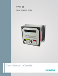
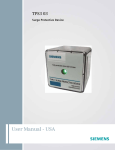
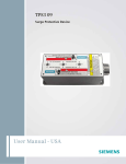
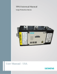
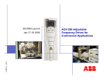
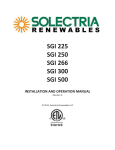
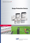
The Rad-X Medical Power Filtration System® (Rad-X Filter) Installation and Service Manual ©APQS 2010 Rad-X Filter Installation & Service Manual TABLE OF CONTENTS SECTION Page(s) BACKGROUND Introduction Unpacking General installation notes 3 3 3 INSTALLATION Mechanical installation Electrical installation 4-5 6-8 MAINTENANCE Front Door indicator lights Internal indicator lights Shutdown procedure General maintenance Fuse Replacement 9 10 11 12 13 MISCELLANEOUS DATA Product Specifications Performance Guarantee 14-18 19 FIGURES Figure 1 Figure 2 Figure 3 Figure 4 Figure 5 Figure 6 Figure 7 Front view of the Rad-X Filter Rear view of the Rad-X Filter with unistrut dimensions Wireway Cabinet detail Diagram of power flow and main circuit breakers Front door indicator lights Internal indicator lights Internal Fuses 4 5 7 8 9 10 13 Rad-X Filter electrical configurations Internal Fuses 3 13 TABLES Table 1 Table 2 ©APQS 2010 2 Rad-X Filter Installation & Service Manual INTRODUCTION The Rad-X Filter is a low pass, bi-directional, pi configuration power filtration system with transient voltage surge suppression (TVSS). It is exclusively designed for application on all X-ray and magnet based medical systems such as CT, CATH, R&F, Linear Accelerator, and MRI. The Rad-X Filter attenuates line and load generated high frequency electrical noise and voltage impulses. Proper installation is required for maximum Rad-X Filter performance. This product should only be installed by a qualified electrical professional. The entire installation manual should be reviewed prior to installation. These instructions do not replace national or local electrical codes. Check applicable electrical codes for compliance. UNPACKING 1. Inspect the shipping boxes for signs of damage or mishandling. 2. Remove the Rad-X Filter and Wireway cabinets from their cartons and inspect for shipping damage. 3. If any damage is observed, immediately contact APQS at 480-214-5676. GENERAL INSTALLATION NOTES 1. The Rad-X Filter should be installed as close as possible to the equipment it is protecting. Ideally, that will be in the treatment or adjacent power room. 2. The Rad-X Filter is manufactured in several electrical configurations (Table 1). Before beginning the installation, check that the Filter you have received matches your electrical system configuration. 3. Contact APQS at 480-214-5676 if there is any question of compatibility. 208/120 Volt 3-Phase Wye 3-phase conductors, 1-neutral and 1-equipment ground conductor 480/277 Volt 3-Phase Wye 3-phase conductors, 1-neutral and 1-equipment ground conductor 480 Volt 3-Phase Delta 3-phase conductors, 1-equipment ground conductor Table 1 ©APQS 2010 3 Rad-X Filter Installation & Service Manual MECHANICAL INSTALLATION 1. The Rad-X Filter includes the Filter Cabinet, the Wireway Cabinet and two, 2" nipples (Figure 1). 2. The product is designed to be wall mounted and is fitted with unistrut ready brackets. Figure 2 illustrates a rear view of the Rad-X Filter Cabinet with unistrut dimensions. Please note that the unistrut and associated hardware is not included with the Rad-X Filter and must be provided by the installing contractor. 3. The Rad-X Filter may be installed at any height (including above a drop ceiling) as long as the required working clearance is met. 4. The required working clearance in the front of the Rad-X Filter is 42”minimum (Refer to the National Electric Code (NEC) Article 110-26). Filter Cabinet 2" Nipples Wireway Cabinet Figure 1 ©APQS 2010 4 Rad-X Filter Installation & Service Manual MECHANICAL INSTALLATION Unistrut ready brackets Rear view of Rad-X Filter Cabinet Unistrut ready brackets Figure 2 ©APQS 2010 5 Rad-X Filter Installation & Service Manual ELECTRICAL INSTALLATION ***All connections are made within the Wireway Cabinet only (Figure 3)*** Final electrical connections between the Rad-X Filter and Wireway Cabinets are made by APQS engineers. The Rad-X Filter is electrically installed in series with the feeder conductors that supply the protected equipment. Whenever possible, it is preferable to install the Rad-X Filter on the line side of the main circuit breaker (CB) that is typically located within the protected equipment suite (Figure 4). For Wye Configuration Rad-X Filters (3-phases, neutral and equipment ground): 1. Make one (1) appropriately sized knock-out on each side of the Wireway Cabinet. 2. Route the Line Side Phase Conductors to the Line Side Distribution Block. (Since the Filter is bi-directional, either side may be set up as the line side.) 3. Route the Line Side Neutral Conductor to the Neutral Distribution Block. 4. Route the Line Side Equipment Ground Conductor to the Ground Distribution Block. 5. Route the Load Side Phase Conductors from the Load Side Distribution Block to the protected equipment. 6. Route the Load Side Neutral Conductor from the Neutral Distribution Block to the protected equipment. 7. Route the Load Side Equipment Ground Conductor from the Ground Distribution Block to the protected equipment. 8. Do not remove the Factory Installed Jumpers. For Delta Configuration Rad-X Filters (3-phases and equipment ground): 1. Make one (1) appropriately sized knock-out on each side of the Wireway Cabinet. 2. Route the Line Side Phase Conductors to the Line Side Distribution Block. (Since the Filter is bi-directional, either side may be used as the line side.) 3. Route the Line Side Equipment Ground Conductor to the Ground Distribution Block. 4. Route the Load Side Phase Conductors from the Load Side Distribution Block to the protected equipment. 5. Route the Load Side Equipment Ground Conductor from the Ground Distribution Block to the protected equipment. 6. Do not remove the Factory Installed Jumpers. ***Ensure that your installation meets all local and national codes*** ©APQS 2010 6 Rad-X Filter Installation & Service Manual ELECTRICAL INSTALLATION WIREWAY CABINET Neutral Distribution Block (Wye Filters Only) Load Side Distribution Block Line Side Distribution Block Line Side Neutral Conductor Load Side Neutral Conductor Factory Installed Jumpers Line Side Phase Conductors Load Side Equipment Ground Conductor Line Side Equipment Ground Conductor Ground Distribution Block Load Side Phase Conductors Figure 3 ©APQS 2010 7 Rad-X Filter Installation & Service Manual POWER FLOW & MAIN CIRCUIT BREAKER DIAGRAM Protected Equipment Suite Rad-X Filter Rad-X Filter installed on the line side of the main circuit breaker (CB) within the protected equipment suite. Main CB Incoming Power Protected Equipment Figure 4 Feeder Conductors from the hospital’s main electrical service to the protected equipment. ©APQS 2010 8 Rad-X Filter Installation & Service Manual FRONT DOOR INDICATOR LIGHTS There are three indicator lights located on the front door of the Rad-X Filter: 1. The top light is the power on indicator. Normally On 2. The middle light is the capacitor bank fault indicator. Normally Off. 3. The bottom light is the TVSS fault indicator. Normally Off. Power On (Normally on) Capacitor Bank Fault (Normally off) TVSS Fault (Normally off) Figure 5 ©APQS 2010 9 Rad-X Filter Installation & Service Manual INTERNAL INDICATOR LIGHTS There are three green lights on the front of the TVSS unit which is located on the inside of the Rad-X Filter Cabinet. These lights are normally on, indicating that the TVSS modules are working. TVSS Lights (Normally on) Internal Plastic Shield Door Circuit Breakers Front Door Figure 6 ©APQS 2010 10 Rad-X Filter Installation & Service Manual SHUTDOWN PROCEDURE ***WARNING*** This procedure should be performed by qualified personnel only. Potentially lethal voltages are present within the Rad-X Filter & Wireway Cabinets. The Rad-X Filter should be shut down prior to working on the protected equipment’s Power Distribution Unit. This is important because the Rad-X Filter’s capacitor banks remain charged even when power to the Filter is turned off. 1. Power down the protected equipment. 2. Determine if the main circuit breaker (CB) controlling power to the protected equipment is electrically installed before or after the Rad-X Filter (Figure 4). 3. If the main CB is installed before the Rad-X Filter: a. Shut the main CB. b. The power-on indicator light (Figure 5) on the Rad-X Filter will extinguish. c. Unlock and open the Rad-X Filter Front Door (Figure 6). d. Open the Internal Plastic Shield Door (Figure 6). e. Using a volt meter, check that power to the Filter is actually off. f. Shut the two Rad-X Filter CB’s (Figure 6). g. The Rad-X Filter is electrically isolated from the protected equipment. 4. If the main CB is installed after the Rad-X Filter: a. Shut the main CB. b. The power-on indicator light on the Rad-X Filter will not extinguish. c. The Rad-X Filter is electrically isolated from the protected equipment. ©APQS 2010 11 Rad-X Filter Installation & Service Manual GENERAL MAINTENANCE The Rad-X Filter does not require regular maintenance. Periodic preventive maintenance is however recommended. Contact APQS for more details. Replacing front cover lights: 1. Unscrew the plastic cap cover. 2. Gently push down on the light bulb and twist it one half turn clockwise. 3. Remove the faulty bulb. 4. Gently push in on the new bulb and twist it one half turn counter clockwise. The TVSS fault indicator light is illuminated: 1. If you notice the red indicator light illuminated, call APQS for service. The capacitor banks on-line light is extinguished: 1. Unlock and open the Rad-X Filter front door. 2. Are the two CB’s in the up position? (up is on, down is tripped)? 3. If both CB’s are up (not tripped), then replace the light bulb. 4. If one or both of the CB’s is down (tripped), call APQS for service. Putting the Rad-X Filter into bypass mode: The Rad-X Filter was initially installed in bypass mode by your electrical contractor. The factory installed jumpers were removed at the time of Filter activation and have been placed within the Wireway Cabinet. 1. Shut down the protected equipment. 2. If the main CB is before the Rad-X Filter, turn off the main CB. If the main CB is after the Rad-X filter, shut the CB that controls power to the protected equipment (Figure 4). 3. The front door power on indicator should be extinguished (Figure 5). 4. Unlock and open the Front Door (Figure 6). 5. Open the Internal Plastic Shield Door (Figure 6). 6. Shut the two CB’s. 7. Open the Wireway Cabinet (Figure 3). 8. Double check that there is no voltage present. 9. Using an appropriate size Hex wrench, loosen the six inner hex nuts. 10. Remove the wires and electrically isolate them with electrical tape. 11. Install the three jumper wires. 12. Close the Wireway Cabinet door. ©APQS 2010 12 Rad-X Filter Installation & Service Manual Fuses CAUTION: There is 277 VAC applied to the primary side of the 50VA transformer The Rad-X Filter has three internal fuses (Figure 7). Table 2 identifies the function of each fuse and it’s rating. Item Fuse 1 Fuse 2 Fuse 3 Function Type Primary leg of the 50 VA transformer Primary leg of the 50 VA transformer Secondary leg of the 50 VA transformer Table 2 1 2 FNQ FNQ FNQ 3 Value 2 Ampere 2 Ampere ½ Ampere 50 VA Transformer Figure 7 Replacing Fuses 1. 2. 3. 4. 5. 6. 7. 8. Shut down power to the Rad-X Filter Trip the two Rad-X Filter internal Circuit Breakers Open the Rad-X Filter front door and the internal plastic door. Remove the Circuit Breaker cover (Figure 6, Page 10). Using an insulated fuse puller, remove the fuse(s) of concern. Replace fuse(s) with the same value and type Close the Circuit Breaker Cover. Close the plastic and front doors. ©APQS 2010 13 Rad-X Filter Installation & Service Manual PRODUCT SPECIFICATIONS 1.0 GENERAL The Rad-X Filter is a low pass, bi-directional, pi configuration power filtration system with transient voltage surge suppression (TVSS). It is manufactured exclusively for imaging, diagnostic and interventional radiology, neurology, oncology and nuclear medicine systems. The Rad-X Filter attenuates high frequency electrical noise and voltage impulses in three ways: 2.0 1.1 Prevents electrical noise generated by sources outside of the protected equipment (line generated disturbances) from getting into the protected equipment. 1.2 Prevents electrical noise generated by the protected equipment itself (load generated disturbances) from echoing back into the protected equipment. 1.3 Prevents electrical noise generated by the protected equipment from affecting other equipment in the area that shares common electrical wiring. PERFORMANCE During normal operation of the protected equipment, the Rad-X Filter will: 2.1 Reduce high frequency electrical noise to below 0.8 volts peak to peak from 1 kHz to 5 MHz, regardless of the electrical noise levels recorded during pre-filter startup monitoring. Monitoring is performed with a BMI, Model 8800 eight-channel disturbance analyzer. 2.2 Eliminate >99% of all voltage impulse activity recorded during the pre-filter startup monitoring. 2.3 Maintain these levels for as long as the protected equipment is in operation. ©APQS 2010 14 Rad-X Filter Installation & Service Manual 3.0 4.0 5.0 6.0 OPERATING SPECIFICATIONS 3.1 Input voltages: 240, 208/120, 480/277, 480 3.2 Input voltage configuration: Delta or Wye 3.3 Maximum continuous current: 160-300 Amperes rms (depending on model) 3.4 Current overload capacity: 200% for 3 minutes 3.5 Impedance: 1.5% @ 60 Hz 3.6 Operating frequency: 60 Hz ± 5% DIMENSIONS 4.1 Main cabinet: 30” High 24” Wide 12” Deep 4.2 Wireway cabinet: 8” High 24” Wide 8” Deep 4.3 Horizontal unistrut dimensions: 22 ½” from mounting bracket center to mounting bracket center. 4.4 Vertical unistrut dimensions: 31 ½” from mounting bracket center to mounting bracket center. WEIGHT 5.1 Main cabinet: 125 lbs (56 kg) 5.2 Wireway cabinet: 20 lbs (9 kg) WIRE SIZE RANGE 6.1 ©APQS 2010 Wire size range #6 AWG to 250 MCM 15 Rad-X Filter Installation & Service Manual 7.0 8.0 ENVIRONMENTAL 7.1 Operating temperature: Humidity: 10°F (-12°C) to 120°F (48°C) 10% to 90% non-condensing 7.2 Storage temperature: Humidity: 0°F (-17°C) to 140°F (60°C) 10% to 90% non-condensing LISTING 8.1 9.0 UL Listed INDUSTRY STANDARDS 9.1 UL 508 9.2 IEEE 587 9.3 UL 1449 9.4 UL 1283 10.0 RECOMMENDED MAINTENANCE 10.1 Yearly preventive maintenance 11.0 WARRANTY 11.1 ©APQS 2010 Five Years from date of Activation 16 Rad-X Filter Installation & Service Manual 12.0 REACTOR SPECIFICATIONS 12.1 System Voltage: 208/240 VAC, 480 VAC, 575/600 VAC 12.2 Insulation System: Class H (180° C) or Class R (220° C) 12.3 Temperature Rise: 115° C or 155° C 12.4 Ambient Temperature: 40° C 12.5 Altitude (Maximum): 1000 meters (Derating necessary above 1000 meters) 12.6 Fundamental Frequency: 60 hz 12.7 Short Term Overload Rating: Tolerate 200% rated I for a minimum of 3 minutes 12.8 Agency Approvals: CE Marked, UL and CUL Recognized 12.9 Inductance Characteristics: Minimum 95%L at 110% Load Minimum 80%L at 150% Load 12.10 Inductance: Distributed Gap Technology™ 12.11 Enclosures: Open, UL Type 1 and UL Type 3R enclosures 12.12 Harmonics Reduction: Three Phase Reactors will reduce RMS current through the reduction in harmonic content, thereby improving the total power factor. ©APQS 2010 17 Rad-X Filter Installation & Service Manual TVSS SPECIFICATIONS 480Y/277 V Input Voltage 240 V 480 V Three Phase Wye 4 wire Three Phase + Ground 3 wire + Ground 240/120 CT 480/240 CT Three Phase 4 wire + Ground Maximum Continuous Operating Voltage (MCOV) 125% of the nominal level for 120 V; 115% for all other input voltages Line Frequency 47-63 Hz Connection /Mounting Type Parallel/Flange Enclosure Metal, NEMA 12 Enclosure Dimensions (H x W x D) 4 x 6 x 4 (inches) Weight 8 lbs. max Modes Of Protection All Mode: L – N , L – L, L – G, N – G Safety Agency Approvals UL 1449-2, UL, UL 1283 UL 1449 (2nd Edition) Suppressor Classification L-N 800 V N/A N/A 400 V 800 V L-L 1500 V 1500 V 1500 V 800 V 1500 V L-G 800 V 1500 V 1500 V 400 V 800 V N-G 800 V N/A N/A 400 V 800 V AIC Rating 65 kAIC Status Indication Response Time Operating Temperature Operating Humidity Fusing Noise Attenuation 3-Green LEDs, 1 per phase, 1-Red LED, Form C Contacts, Audible Alarm <0.5 nsec -40o C to +60o C 0% to 95% Non-condensing Thermal and Fault Current 40 dB Max Peak Surge Current Capability Per Phase 100 kA 100 kA 100 kA 100 kA 100 kA Line to Neutral 50 kA N/A N/A 50 kA 50 kA Line to Line 50 kA 50 kA 50 kA 50 kA 50 kA Line to Ground 50 kA 50 kA 50 kA 50 kA 50 kA Neutral to Ground 50 kA N/A N/A 50 kA 50 kA Warranty 10 Years ©APQS 2010 18 Rad-X Filter Installation & Service Manual PERFORMANCE GUARANTEE APQS will guarantee that if during the first year of Rad-X Filter operation, the hospital does not save at least the purchase price of the Filter in reduced non-mechanical related maintenance costs, or downtime, the hospital may choose to return the Rad-X Filter to APQS for a full refund.* *Client is obligated to provide APQS with verifiable cost of maintenance records of the filtered system for the year of Rad-X Filter operation and the year prior to Rad-X Filter installation. Applied Power Quality Solutions, LLC P.O. Box 14915 Scottsdale, AZ 85267-4915 Tel: (480) 214-5676 Fax: (480) 214-5677 www.appliedpqs.com While every precaution has been taken to ensure completeness and accuracy in this manual, APQS assumes no responsibility, and disclaims all liability for damages resulting from use of this information or for any errors or omissions. APQS reserves the right to make changes to this manual without prior notification. The APQS Logo and Rad-X Medical Power Filtration System are trademarks of APQS. ©APQS 2010 19 Rad-X Filter Installation & Service Manual