1
FETALGARD Lite™
Fetal Monitor
OPERATOR’S MANUAL
Proprietary Material
Information and descriptions contained in this manual are the property of
Analogic Corporation and may not be copied, reproduced, disseminated, or
distributed without express written permission from Analogic Corporation.
Information furnished by Analogic Corporation is believed to be accurate and
reliable. However, no responsibility is assumed by Analogic for its use, or any
infringements of patents or other rights of third parties that may result from its
use. No license is granted by implication or otherwise under any patent or
patent rights of Analogic.
16-400823 Revision 3
January 2001, May 2001, June 2001
Copyright © Analogic Corporation 2000. All rights reserved.
MedaSonics//®
a division of
CooperSurgical
15 Forest Parkway
Shelton, CT 06484
Tel: (800) 243-2974
Printed in U.S.A.
i
Fetalgard Lite Operator’s Manual
Preface
The FETALGARD Lite Operator’s Manual contains all of the information the
operator needs to operate the FETALGARD Lite monitor system, including:
Monitor Software
Revision 1.xx
View Software
Revision 1.xx
Recorder Firmware
Revision 1.xx
If the software version of your product is not in the range from 1.00 to 1.99,
please contact your sales representative to obtain addendum pages or a replacement manual that describes the operation of your version of the product.
The FETALGARD Lite Operator’s Manual is intended for trained medical
personnel (including midwives, nurses, and physicians) who are familiar with
obstetric procedures. Keep this operator’s manual with the unit for use by the
operator.
ii
Table of Contents
1
SAFETY . . . . . . . . . . . . . . . . . . . . . . . . . . . . . . . . . . . . . . .1-1
1.1
1.2
1.3
1.4
2
INTRODUCTION . . . . . . . . . . . . . . . . . . . . . . . . . . . . . . . . .2-1
2.1
2.2
2.3
2.4
2.5
3
Instructions for the Safe Operation and Use of the FETALGARD Lite . . .
Family of Monitors . . . . . . . . . . . . . . . . . . . . . . . . . . . . . . . . . . . . . . . . . .1-1
Warnings . . . . . . . . . . . . . . . . . . . . . . . . . . . . . . . . . . . . . . . . . . . . . . . . . .1-2
Cautions . . . . . . . . . . . . . . . . . . . . . . . . . . . . . . . . . . . . . . . . . . . . . . . . . . .1-2
Definitions of Symbols . . . . . . . . . . . . . . . . . . . . . . . . . . . . . . . . . . . . . . .1-4
General . . . . . . . . . . . . . . . . . . . . . . . . . . . . . . . . . . . . . . . . . . . . . . . . . . . .2-1
Brief Device Description . . . . . . . . . . . . . . . . . . . . . . . . . . . . . . . . . . . . . .2-1
Intended Use . . . . . . . . . . . . . . . . . . . . . . . . . . . . . . . . . . . . . . . . . . . . . . .2-1
Product Features . . . . . . . . . . . . . . . . . . . . . . . . . . . . . . . . . . . . . . . . . . . .2-1
Models, Options, and Accessories . . . . . . . . . . . . . . . . . . . . . . . . . . . . . .2-2
INSTALLATION, SETUP AND OPERATION . . . . . . . . . .3-1
3.1
3.2
3.3
3.4
3.5
3.6
3.7
Description of the Front Panel . . . . . . . . . . . . . . . . . . . . . . . . . . . . . . . . . .3-1
Description of the Rear Panel . . . . . . . . . . . . . . . . . . . . . . . . . . . . . . . . . .3-2
Patient Cables . . . . . . . . . . . . . . . . . . . . . . . . . . . . . . . . . . . . . . . . . . . . . . .3-3
Remote Marker Cable . . . . . . . . . . . . . . . . . . . . . . . . . . . . . . . . . . . . . . . .3-3
Battery Eliminator . . . . . . . . . . . . . . . . . . . . . . . . . . . . . . . . . . . . . . . . . . .3-3
GCX Mounting Plate . . . . . . . . . . . . . . . . . . . . . . . . . . . . . . . . . . . . . . . . .3-4
FETALGARD Lite Monitor Display Screen . . . . . . . . . . . . . . . . . . . . . .3-5
3.7.1 Fetal Heart Numeric . . . . . . . . . . . . . . . . . . . . . . . . . . . . . . . . . . . .3-5
3.7.2 Heart Rate Trend . . . . . . . . . . . . . . . . . . . . . . . . . . . . . . . . . . . . . .3-6
3.7.3 TOCO Numeric . . . . . . . . . . . . . . . . . . . . . . . . . . . . . . . . . . . . . . .3-6
3.7.4 TOCO Trend . . . . . . . . . . . . . . . . . . . . . . . . . . . . . . . . . . . . . . . . .3-6
3.7.5 Power Status . . . . . . . . . . . . . . . . . . . . . . . . . . . . . . . . . . . . . . . . . .3-7
3.7.6 Communications . . . . . . . . . . . . . . . . . . . . . . . . . . . . . . . . . . . . . .3-7
3.7.7 Patient ID . . . . . . . . . . . . . . . . . . . . . . . . . . . . . . . . . . . . . . . . . . . .3-7
3.7.8 Time and Date . . . . . . . . . . . . . . . . . . . . . . . . . . . . . . . . . . . . . . . .3-8
3.7.9 Error Display . . . . . . . . . . . . . . . . . . . . . . . . . . . . . . . . . . . . . . . . .3-8
3.8 FETALGARD Lite Monitor Controls and Indicators . . . . . . . . . . . . . . .3-8
3.9 FETALGARD Lite Monitor Control Knob . . . . . . . . . . . . . . . . . . . . . . .3-9
3.10 Startup 3-9
3.10.1 Power-on Self-test . . . . . . . . . . . . . . . . . . . . . . . . . . . . . . . . . . . .3-9
3.10.2 Configuration Settings . . . . . . . . . . . . . . . . . . . . . . . . . . . . . . . .3-10
3.10.3 Setting U/S Trace Separation . . . . . . . . . . . . . . . . . . . . . . . . . .3-11
3.10.4 Setting TOCO Baseline . . . . . . . . . . . . . . . . . . . . . . . . . . . . . . .3-12
3.10.5 Setting Time, Date, and Display Format . . . . . . . . . . . . . . . . .3-13
3.10.6 Setting Patient ID . . . . . . . . . . . . . . . . . . . . . . . . . . . . . . . . . . . .3-14
3.10.7 Setting the Language Configuration . . . . . . . . . . . . . . . . . . . . .3-16
iii
Fetalgard Lite Operator’s Manual
3.10.8 Setting Modem Parameters . . . . . . . . . . . . . . . . . . . . . . . . . . . .3-17
3.10.9 Setting Recorder Parameters . . . . . . . . . . . . . . . . . . . . . . . . . . .3-18
3.10.10 Understanding and Setting Alarms . . . . . . . . . . . . . . . . . . . . . .3-19
3.10.11 Adjusting the Display Contrast . . . . . . . . . . . . . . . . . . . . . . . . .3-20
3.10.12 Adjusting Speaker Volume . . . . . . . . . . . . . . . . . . . . . . . . . . . .3-21
3.11 FETALGARD Lite Recorder . . . . . . . . . . . . . . . . . . . . . . . . . . . . . . . . .3-21
3.11.1 Installation and Loading Paper . . . . . . . . . . . . . . . . . . . . . . . . .3-21
3.119.2 Controls and Indicators . . . . . . . . . . . . . . . . . . . . . . . . . . . . . . .3-23
4
MONITORING FETAL HEART RATE . . . . . . . . . . . . . . . .4-1
5
MONITORING UTERINE ACTIVITY (UA) . . . . . . . . . . . . .5-1
6
REMOTE PATIENT MARKER AND
CLINICIAN MARKER . . . . . . . . . . . . . . . . . . . . . . . . . . . . .6-1
6.1
6.2
Clinician Marker . . . . . . . . . . . . . . . . . . . . . . . . . . . . . . . . . . . . . . . . . . . .6-1
Remote Patient Marker . . . . . . . . . . . . . . . . . . . . . . . . . . . . . . . . . . . . . . .6-1
7
USING GRATICULES . . . . . . . . . . . . . . . . . . . . . . . . . . . . .7-1
8
USING TREND SCROLL . . . . . . . . . . . . . . . . . . . . . . . . . .8-1
9
PRINTING PATIENT FILES . . . . . . . . . . . . . . . . . . . . . . . .9-1
10
TRANSFERRING PATIENT DATA . . . . . . . . . . . . . . . . . .10-1
10.1 Troubleshooting . . . . . . . . . . . . . . . . . . . . . . . . . . . . . . . . . . . . . . . . . . . .10-3
11
FETALGARD LITE VIEW . . . . . . . . . . . . . . . . . . . . . . . . .11-1
11.1
11.2
11.3
11.4
11.5
iv
Overview . . . . . . . . . . . . . . . . . . . . . . . . . . . . . . . . . . . . . . . . . . . . . . . . .11-1
Installation . . . . . . . . . . . . . . . . . . . . . . . . . . . . . . . . . . . . . . . . . . . . . . . .11-1
Starting FETALGARD Lite View . . . . . . . . . . . . . . . . . . . . . . . . . . . . .11-2
Display Screen . . . . . . . . . . . . . . . . . . . . . . . . . . . . . . . . . . . . . . . . . . . . .11-2
Menu System . . . . . . . . . . . . . . . . . . . . . . . . . . . . . . . . . . . . . . . . . . . . . .11-3
12
FETALGARD LITE RECEIVER . . . . . . . . . . . . . . . . . . . .12-1
12.1
12.2
12.3
12.4
12.5
13
Overview . . . . . . . . . . . . . . . . . . . . . . . . . . . . . . . . . . . . . . . . . . . . . . . . .12-1
Installation . . . . . . . . . . . . . . . . . . . . . . . . . . . . . . . . . . . . . . . . . . . . . . . .12-1
Starting FETALGARD Lite Receiver . . . . . . . . . . . . . . . . . . . . . . . . . .12-2
User Interface . . . . . . . . . . . . . . . . . . . . . . . . . . . . . . . . . . . . . . . . . . . . . .12-2
Installation of the Recorder . . . . . . . . . . . . . . . . . . . . . . . . . . . . . . . . . . .12-3
CLEANING . . . . . . . . . . . . . . . . . . . . . . . . . . . . . . . . . . . .13-1
13.1 Monitor . . . . . . . . . . . . . . . . . . . . . . . . . . . . . . . . . . . . . . . . . . . . . . . . . . .13-1
13.2 Recorder . . . . . . . . . . . . . . . . . . . . . . . . . . . . . . . . . . . . . . . . . . . . . . . . . . .13-1
13.3 Transducers . . . . . . . . . . . . . . . . . . . . . . . . . . . . . . . . . . . . . . . . . . . . . . . .13-2
13.4 Belts
. . . . . . . . . . . . . . . . . . . . . . . . . . . . . . . . . . . . . . . . . . . . . . . . . . .13-3
14
SPECIFICATIONS . . . . . . . . . . . . . . . . . . . . . . . . . . . . . . .14-1
15
TROUBLESHOOTING AND MAINTENANCE . . . . . . . .15-1
15.1 Self Test . . . . . . . . . . . . . . . . . . . . . . . . . . . . . . . . . . . . . . . . . . . . . . . . . .15-1
15.2 Ultrasound Transducer Test . . . . . . . . . . . . . . . . . . . . . . . . . . . . . . . . . . .15-1
15.3 TOCO Test . . . . . . . . . . . . . . . . . . . . . . . . . . . . . . . . . . . . . . . . . . . . . . . .15-2
15.4 Battery Handling and Disposal . . . . . . . . . . . . . . . . . . . . . . . . . . . . . . . .15-2
15.5 Maintenance . . . . . . . . . . . . . . . . . . . . . . . . . . . . . . . . . . . . . . . . . . . . . . . .15-2
v
Safety
Section 1
Safety
1.1
Instructions for the Safe Operation and Use of the
FETALGARD Lite™ Family of Monitors
• Examine the monitor and any accessories periodically to ensure that the
cables, line cords, transducers, and instruments do not have visible evidence
of damage that may affect patient safety or monitoring performance. The
recommended inspection interval is once per week or less. Do not use the
monitor if there is any visible sign of damage.
• Only the Battery Eliminator supplied with the device is approved for use in
supplying external power for operation and recharging the internal batteries.
• Only the AC line cord supplied with the FETALGARD Lite Recorder, or its
equivalent, is approved for use with the Recorder.
• Do not attempt to service the FETALGARD Lite monitor or recorder. Only
qualified service personnel should attempt any needed internal servicing.
• The FETALGARD Lite is not specified or intended for operation during the
use of defibrillators or during defibrillator discharge.
• The FETALGARD Lite is not specified or intended for operation in the presence of electrosurgical equipment.
• The FETALGARD Lite is not specified or intended for operation in conjunction with any other type of monitoring equipment except the specific devices
that have been identified for use in this Operator’s Manual.
• Perform periodic safety testing to insure proper patient safety. This should
include leakage current measurement and insulation testing. The recommended testing interval is once per year.
• Do not operate the FETALGARD Lite monitor if it fails to pass the power
on self-test procedure.
1-1
FETALGARD Lite Operator’s Manual
1.2
Warnings
WARNING: EXPLOSION HAZARD — Do not use the FETALGARD Lite
in a flammable atmosphere where concentrations of flammable anesthetics or
other materials may occur.
WARNING: SHOCK HAZARD — The power receptacle must be a threewire grounded outlet. Never adapt the three-prong plug from the Battery
Eliminator or accessory to fit a two-slot outlet. If the outlet has only two slots,
make sure that it is replaced with a three-slot grounded outlet before attempting to operate the monitor.
WARNING: Do not connect to an electrical outlet controlled by a wall switch.
WARNING: SHOCK HAZARD — Do not attempt to connect or disconnect a
power cord with wet hands. Make certain that your hands are clean and dry
before touching a power cord.
WARNING: Use only patient cables and transducers supplied with the monitor. Use of any other patient cables may result in out-of-specification performance and possible safety hazards.
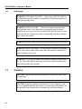
1.3
Cautions
CAUTION: United States Law restricts this device to sale by or on the order
of a physician.
CAUTION: Keep the operating environment free of dust, vibrations, corrosive, or flammable materials, and extremes of temperature and humidity. The
unit should be kept clean and free of transducer gel and other substances.
1-2
Safety
CAUTION: When installing the unit into a cabinet, allow for adequate ventilation, accessibility for servicing, and room for adequate visualization and operation.
CAUTION: Do not operate the unit if it is damp or wet because of condensation or spills. Avoid using the equipment immediately after moving it from a
cold environment to a warm, humid location.
CAUTION: Never use sharp or pointed objects to operate the front-panel
switches.
CAUTION: General-purpose personal computers and modems are not
designed to meet the electrical safety requirements of medical devices. The
RS-232 connector on the FETALGARD Lite is electrically isolated to permit
safe connections to non-medical devices, which should be connected with a
cable of sufficient length to prevent the non-medical equipment from contacting the patient.
CAUTION: Do not autoclave or gas sterilize the monitor or any accessories.
Follow cleaning and disinfection instructions in Section 12 of this manual.
CAUTION: Do not immerse transducers in liquid. When using solutions, use
sterile wipes to avoid pouring fluids directly on the transducer. Follow cleaning and disinfection instructions in Section 12 of this manual.
CAUTION: When washing the transducer belts, the water temperature must
not exceed 60°C (140°F).
1-3
FETALGARD Lite Operator’s Manual
1.4
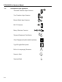
Definitions and Symbols
Ultrasound Transducer Input Connector
Toco Transducer Input Connector
Remote Marker Input Connector
RS-232 Connector
Battery Eliminator Connector
Ð
+
IPX1
Drip-proof Equipment Classification
Class II Equipment Symbol (double insulation)
Type BF Applied Part Symbol
Refer to Accompanying Documents
Protective Earth
Functional Earth
1-4
!
Introduction
Section 2
Introduction
2.1
General
This chapter provides a general description of the FETALGARD Lite monitor
including:
• Brief Device Description
• Product Features
• Model Configurations
2.2
Brief Device Description
The FETALGARD Lite is a family of microprocessor-based fetal monitors,
providing continuous monitoring, display, and recording of fetal heart rate
(FHR) and uterine activity (UA) for antepartum testing and monitoring.
2.3
Intended Use
The FETALGARD Lite is a Perinatal Monitoring System for non-invasively
measuring and showing graphically maternal abdominal contractions and the
fetal heart rate by means of display on a non-permanent graphical display and
optionally on a strip chart recorder. This data is intended to aid in assessing the
well being of the fetus during the final trimester of pregnancy (Non-Stress
Test). This device is for use only by trained medical personnel located in hospitals, clinics, doctors’ offices and in the patient’s home.
2.4
Product Features
The monitored data can be recorded continuously or intermittently on a stripchart recorder at the operator’s discretion. The recorded information includes
graphic trend data and text information of monitor hardware and software configuration, date and time, patient identification, changes to operational settings, clinician and patient event marks, and recorder model and paper configurations.
2-1
FETALGARD Lite Operator’s Manual
2.5
Models, Options, and Accessories
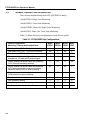
There are four standard models in the FETALGARD Lite family.
• Model FGD01: Single-Fetus Monitoring
• Model FGD02: Twins-Fetus Monitoring
• Model FGDHC: Home Care Single-Fetus Monitoring
• Model FGDT: Home Care Twins-Fetus Monitoring
Table 2-1 defines the factory configurations of each of these models.
Table 2-1. FETALGARD Lite Configurations
Factory Configuration
Monitoring Features and Included Items
2-2
Model
FGD01
Model
FGD02
Model Model
FGDHC FGDT
Fetal Heart Rate (FHR) – Single-Fetus monitoring
X
X
X
X
Fetal Heart Rate (FHR) – Twin-Fetus monitoring
No
X
No
X
Tocotonometer (TOCO) with belt
X
X
X
X
Recorder with line cord configured for country of
intended use, I/O cable and 2 packs of paper
X
X
No
No
Factory-installed ultrasound cable and transducer
(U/S1) for single monitoring with belt
X
No
X
No
Factory-installed ultrasound cable and transducer
(U/S1) with belt and with connector for second
transducer cable (U/S2) for twins monitoring
No
X
No
x
Second ultrasound cable and attached transducer
(U/S2) with belt for twins monitoring
No
X
No
X
One tube of ultrasound gel
X
X
X
X
One Operator’s manual
X
X
X
X
One table-top Battery Eliminator
X
X
X
X
One line cord for ordered U.S. or European use
X
X
X
X
Introduction
Table 2-2 indicates the Accessories that are designed for use with any of the
models.
Table 2-2. FETALGARD Lite Accessories
Accessory Description
MedaSonics//® Part Number
FG Lite Recorder w/cable 115V
FG REC-115
FG Lite Recorder Cable
REC
Single U/S Trans w/belt
UT
Single U/S Trans w/Y & belt
UTY
Second U/S Trans w/belt
UTYT
Tocotonometer w/belt
TOCO
Battery Eliminator 115V
BE-115
FG Lite Service Manual
FGSM
Remote Marker
RM01
FG Lite View Program
FGSP
GCX Adapter
FGGCX
FG Lite Carrying Case
FGCC
2-3
Installation, Setup, and Operation
Section 3
Installation, Setup, and Operation
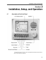
3.1
Description of the Front Panel
This figure shows the location of the various parts and controls on the front of
the FETALGARD Lite monitor.
3-1
FETALGARD Lite Operator’s Manual
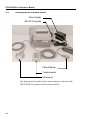
3.2
Description of the Rear Panel
Power Supply
RS-232 Connector
Patient Marker
Tocotonometer
Ultrasound
This figure shows the location of the various connectors on the rear of the
FETALGARD Lite monitor, with accessories attached.
3-2
Installation, Setup, and Operation
3.3
Patient Cables
The ultrasound transducer and TOCO transducer are attached to the rear of the
monitor. Each cable has a tab located on the connector housing to insure proper insertion into the appropriate connector on the monitor. The location of the
connectors is shown on the label located on the rear of the monitor.
The cables are inserted or removed by squeezing the narrow ends of the connector housing. This releases the connector locking mechanism.
A second ultrasound transducer and cable are supplied with the version of the
FETALGARD Lite capable of monitoring two fetuses. This second transducer
comes with a shorter cable that inserts into a connector located on the primary
ultrasound transducer cable. To install the second transducer, remove the protective cover from the connector on the primary cable and insert the second
transducer cable.
WARNING: Use only patient cables and transducers supplied with the monitor. Use of any other patient cables may result in out-of-specifications performance and possible safety hazards.
3.4
Remote Marker Cable
The remote marker cable is inserted into a connector on the rear. The rear
label shows the location of the connector. The cable connector is inserted into
the connector firmly until it is fully engaged.
3.5
Battery Eliminator
The battery eliminator is used to charge the monitor’s internal battery. The
battery can be charged either during normal fetal monitoring or when off. The
battery eliminator consists of a tabletop box with a permanently attached cable
and a separate AC line cord. The attached cable is inserted into its mating connector located on the rear of the monitor.The label on the rear of the monitor
shows the location of this mating connector. Insert the cable into this connector firmly until it is fully engaged.
Insert the AC line cord into the three-pronged IEC receptacle on the battery
eliminator. The other end of the AC line cord is then inserted into an appropriate wall outlet.
3-3
FETALGARD Lite Operator’s Manual
WARNING: SHOCK HAZARD — The power receptacle must be a threewire grounded outlet. Never adapt the three-prong plug from the Battery
Eliminator or accessory to fit a two-slot outlet. If the outlet has only two slots,
make sure that it is replaced with a three-slot grounded outlet before attempting to operate the monitor.
WARNING: Do not connect to an electrical outlet controlled by a wall switch.
WARNING: SHOCK HAZARD — Do not attempt to connect or disconnect a
power cord with wet hands. Make certain that your hands are clean and dry
before touching a power cord.
3.6
GCX Mounting Plate
The GCX mounting plate attaches to the bottom of the monitor by sliding the
narrow piece of the mounting plate into the slot on the bottom of the monitor.
The spring loaded plunger will snap into place when the GCX mounting plate
is fully engaged. To remove the mounting plate simply pull on the spring
loaded plunger until the plate is free to slide out.
The monitor and GCX plate is attached to a standard GCX roll stand (GCX
part number ANA-0001064).
3-4
Installation, Setup, and Operation
3.7
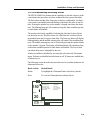
FETALGARD Lite Monitor Display Screen
Main Monitoring Screen (Twins Configuration)
Heart rate
Numeric Frame
(Twins configuration)
TOCO Numeric
Frame
U/S 1
240
150
160
U/S 2
120
132
TOCO Trend
Frame
30
100
TOCO
20
Heart Rate
Trend Frame
(5)
0
Communications
Frame
Jane Doe 194848
3
16:34:12
cm/min.
Power Status Frame
Patient ID
Frame
2/14/96
Time/Date Frame
Main Monitoring Screen (Single Configuration)
U/S 1
240
150
160
120
30
TOCO
100
20
(5)
0
3
cm/min.
Jane Doe 194848
16:34:12 2/14/96
3.7.1 Heart Rate Numeric
The heart rate numeric frame displays the fetal heart rate, a heart icon, alarm
status icon, and a speaker volume icon. This channel is labeled “U/S 1.” The
heart rate value shows the most recent calculated fetal heart rate. The heart
rate icon blinks at the measured heart rate interval when a valid rate is present.
3-5
FETALGARD Lite Operator’s Manual
The volume icon provides an indication of the speaker volume setting for the
fetal echo sounds. This icon changes when the speaker volume setting is adjusted. The alarm icon is a bell. A diagonal line through the bell indicates alarms
are disabled. A bell missing a diagonal line indicates alarms are enabled.
When the second ultrasound transducer is installed, the heart rate frame will
include additionally the fetal heart rate, a heart rate icon, alarm status icon, and
a speaker volume icon for the second ultrasound channel. These function identically as described above. This channel is labeled “U/S 2.”
The trace-offset icon will also appear in the heart rate frame if two ultrasound
transducers are installed and ultrasound trace offset has been enabled. The
trace-offset icon is a downward pointing arrow.
3.7.2 Heart Rate Trend
The Heart Rate Trend Frame displays a graphical representation of the fetal
heart rate. The vertical scale is labeled and corresponds to the selection of
recorder paper (30 to 240 BPM for U.S. style paper, 50 to 210 BPM for international style paper). The graph displays 6 minutes of data if the monitor is set
for a print speed of 3 cm per minute, 9 minutes of data when set for 2 cm per
minute, and 18 minutes when set to 1 cm per minute.
This frame will show two heart rate trends when two ultrasound transducers
are installed.
Two horizontal graticules are included to make it easier for the caregiver to
observe heart rate trend or heart rates that exceed limits. The position of these
two graticules is 120 BPM and 160 BPM.
This graphical frame is also used to display heart rate data when scrolling
through historical patient data.
3.7.3 TOCO Numeric
This frame contains the numeric value from the TOCO transducer representing uterine activity. This frame also shows the present TOCO baseline value.
The TOCO baseline is user adjustable.
3.7.4 TOCO Trend
The TOCO Trend Frame displays uterine activity trend data. The scale is from
zero to 100 in relative units. The graph displays 6 minutes of data if the monitor
is set for a print speed of 3 cm per minute, 9 minutes of data when set for
2 cm per minute, and 18 minutes when set to 1 cm per minute. This graphical
frame also displays uterine activity data when scrolling through patient data.
3-6
Installation, Setup, and Operation
3.7.5 Power Status
This frame contains either a battery icon or an AC power connector icon. If
the unit is operating on AC power then an AC power connector icon is displayed. If the monitor is operating on internal battery power then a battery
icon is displayed. The battery icon also includes a scale indicating battery
charge status.
The battery icon will flash when the battery is low (less than 30 minutes of
remaining time). The battery eliminator should be connected to the monitor to
charge the battery. The monitor will operate normally while the battery eliminator is charging the battery. The battery will be fully recharged in 8 hours if
the monitor is not in use, or in 14 hours while in normal use.
3.7.6 Communications
This frame shows the status of devices connected to the monitor’s serial interface port.
Icon
Description
This phone icon appears if the monitor is connected to an external
modem and no call is in process.
This icon appears when the connected modem is making a call to
another modem. The call is in process and an attempt is being made
to connect to another device.
This icon appears when the attached modem is transferring patient
data files.
This icon appears when the monitor is connected directly to an
external computer and they are able to communicate with each
other.
This icon appears when the monitor is connected to the FETALGARD Lite Recorder. This icon is accompanied by the present setting for print speed.
3.7.7 Patient ID
This section displays the patient identification. The monitor uses a time and
date encoded identification scheme that insures no duplication of names. The
user may also enter a different name if desired.
3-7
FETALGARD Lite Operator’s Manual
3.7.8 Time and Date
This frame shows the current time and date for the monitor. These settings can
be changed as needed. The format for time and date is also user configurable.
3.7.9 Error Display
Error 0x1003456
Refer to Service Manual
The error screen will be displayed when the monitor is unable to operate properly. If this screen appears, discontinue use of monitor. Refer to the service
manual for appropriate action.
3.8
FETALGARD Lite Monitor Controls and Indicators
There are seven buttons located on the front panel. The buttons are activated
by pushing with the finger until an audible click is heard.
CAUTION: Never use sharp or pointed objects to operate the front-panel
switches.
The operation of the buttons is summarized below.
Icon
Description
Power On/Off button — turns monitor power on and off.
U/S Volume Select button — selects an ultrasound channel in order
to adjust its audio volume. The control knob is then used to increase
or decrease volume settings. This button is also used to silence the
audible warning indicator that accompanies a heart rate alarm condition.
0
TOCO Zero button — resets the TOCO baseline.
Clinician Event Marker button — inserts a nurse event mark on the
display and strip chart paper when pressed.
Contrast Adjust button — changes the operation of the control knob
for adjusting the display contrast.
3-8
Installation, Setup, and Operation
Trend Scroll button — this button puts the monitor into trend scroll
mode. The trend frames shows historical patient data and the control knob provides navigation capability.
Graticule button — displays a pair of horizontal level lines, 15 BPM
apart, on the FHR trend frame. Rotating the control knob moves
these lines up or down on the display.
The keypad has two LED indicators. The indicator next to the battery symbol
is on whenever the monitor is powered from the internal battery. The indicator
next to the power cord connector symbol is on whenever the monitor is powered from AC mains via the external battery eliminator.
3.9
FETALGARD Lite Monitor Control Knob
The Control Knob is the primary method of adjusting parameters and navigating through the menu system. Rotating the knob while in the main monitoring
screen moves a selection frame to each of the frames in the display. When the
knob is pressed, a menu appears that contains monitor settings that are relevant to the display frame that was selected.
If the knob is rotated while in a menu, the cursor moves throughout the items
within the menu. This process is used to select a menu item for modification.
The knob is then pressed to select this item for editing.
Once a menu item has been selected for editing, the knob is rotated to scan
through the available choices for this parameter. Pressing the knob stores the
new value.
Pressing the knob when “Return” is selected will exit the present menu. In
some cases this action will return the monitor to the main monitoring screen.
In other cases the monitor will display the previous menu.
Specific Control Knob procedures are included in the chapters describing
setup, monitoring, recording and viewing patient data.
3.10
Startup
3.10.1 Power-on Self-test
The monitor performs a self-test each time it is turned on. This process allows
the monitor to check various systems for proper operation. The monitor displays the startup screen during the power-on self-test. When the test is successfully completed the FETALGARD Lite displays the monitoring screen.
3-9
FETALGARD Lite Operator’s Manual
If a malfunction is detected an error screen appears and an error tone is sounded. The error tone will continue until the power is turned off. If this occurs,
remove the monitor from service until appropriate action is taken.
3.10.2 Configuration Settings
The monitor has several configuration settings that the user can change. Some
of these settings are reset to the default value each time the monitor is powered
down. Other parameter settings are saved in the monitor until the next time
they are changed. These parameters are unaffected when the monitor is powered down. A complete list of these parameters is shown below.
Configuration Parameter
3-10
Factory Default
Saved Until Changed
U/S Trace Separation
0 BPM
No
TOCO Baseline Set Point
10
Yes
Time Format
12-hour
Yes
Date
“today”
Yes
Date Format
mm/dd/yy
Yes
Patient Id
Time/Date encoded No
Language
English
Yes
Modem Initialization String
—
Yes
Modem Phone Number
—
Yes
Recorder Paper Speed
3 cm/min
Yes
Recorder Paper Vendor
Analogic
Yes
Recorder Paper Style
U.S.A.
Yes
Alarms
Disabled
Yes
U/S Heart Rate Upper
Alarm Limit
120 BPM
Yes
U/S Heart Rate Lower
Alarm Limit
60 BPM
Yes
Heart Rate Alarm Delay
15 seconds
Yes
Loss of Heart Rate
Alarm Delay
120 seconds
Yes
Display Contrast
—
Yes
Speaker Volume
—
Yes
Installation, Setup, and Operation
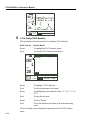
3.10.3 Setting U/S Trace Separation
When ultrasound trace separation is enabled, the trend data for ultrasound
channel 2 is shifted down by 20 BPM. This feature is provided to clearly see
separate heart rate trends when both heart rates are similar. The heart rate
value shown in the numeric frame is not affected.
Follow the steps below to change the heart rate separation setting.
Knob Activity
Desired Result
Rotate
To highlight the heart rate frame.
Press
To view the ultrasound menu (shown below).
U/S 1
Ultrasound Menu
150
Trace Separation
FHR Upper Limit
FHR Lower Limit
FHR Alarm Delay
Loss of FHR Delay
Alarm Status
(0 bpm)
(120 bpm)
(60 bpm)
(15 seconds)
(120 seconds)
(Disable)
TOCO
20
Return
(5)
3
cm/min
Jane Doe 194848
16:34:12
2/14/96
Rotate
To select Trace Separation.
Press
To select this parameter for change.
Rotate
To select “0 BPM,” or “20 BPM.”
Press
To keep this selection.
Rotate
To select “Return.”
Press
To exit this submenu and return to the main monitoring
screen
When trace separation is activated, it is indicated on the monitoring display by
an arrow pointing downward next to the U/S 2 numeric value. This indicator
will flash at a 1 Hz rate.
3-11
FETALGARD Lite Operator’s Manual
U/S 1
240
150
160
U/S 2
120
132
30
TOCO
20
100
(5)
0
cm
3 min.
0
Jane Doe 194848
16:34:12 2/14/96
3.10.4 Setting TOCO Baseline
This section describes the procedure for setting the TOCO baseline.
Knob Activity
Desired Result
Rotate
To highlight the TOCO numeric frame.
Press
To view the TOCO menu (shown below).
U/S 1
TOCO Menu
TOCO Baseline
(5)
150
TOCO
20
Return
(5)
3
cm/min
Jane Doe 194848
16:34:12
2/14/96
Rotate
To highlight “TOCO Baseline.”
Press
To select this parameter for change.
Rotate
To highlight the desired baseline value (“5,” “10,” “15,” or
“20”).
Press
To keep this selection.
Rotate
To select “Return.”
Press
To exit this submenu and return to the main monitoring
screen.
The new baseline value is displayed in parentheses in the TOCO numeric
frame.
3-12
Installation, Setup, and Operation
3.10.5 Setting Time, Date, and Display Format
This section describes the procedure used to change the time and date settings
of the monitor.
Knob Activity
Desired Result
Rotate
To highlight the Time and Date Frame with a heavy border.
Press
To view the Time/Date menu (shown below). Next to each
parameter is the present setting in parentheses.
U/S 1
Time/Date Menu
Set Time
Set Date
Set Time Format
Set Date Format
150
(24 Hour)
(MM/DD/YY)
TOCO
20
Return
(5)
3
Jane Doe 194848
cm/min
16:34:12
2/14/96
Rotate
To highlight the item you want to change (“Set Time,” “Set
Time Format,” “Set Date,” or “Set Date Format”).
Press
To select this item for editing.
Rotate
To highlight the parameter value for editing. The options
for each parameter in the submenu are:
Time
Date
Time Format
Date Format
{hours, minutes, seconds}
{month, day, year}
{12 Hour, 24 Hour}
{MM/DD/YY, DD/MM/YY}
Press
To select the parameter value for editing.
Rotate
To choose new values for the parameter.
Press
To keep the displayed value for this parameter.
Repeat the previous steps for each parameter you wish to
change.
Rotate
To select “Return.”
Press
To exit this menu.
The new time, date, and format selections are displayed on the main monitoring screen.
3-13
FETALGARD Lite Operator’s Manual
3.10.6 Setting Patient ID
This section describes the procedure used to change the patient ID. When the
monitor is turned on a default patient ID is created by the monitor based upon
the present time and date. When this default patient ID is changed, the new
patient ID will be incorporated into the stored patient record within the monitor and presented on the display. If the patient ID is changed a second time the
monitor assumes a new patient and automatically creates a new patient record.
Knob Activity
Desired Result
Rotate
To highlight the Patient ID Frame with a heavy border.
Press
To view the Patient ID menu (shown below). The present
patient ID is displayed in parentheses.
Patient ID Menu
U/S 1
Patient ID
(*0214961630)
150
TOCO
20
Return
(5)
*0214961630
3
cm/min
16:34:12
Rotate
To highlight “Patient ID.”
Press
To select “Patient ID” for editing. The Set Patient ID submenu will appear (shown below).
U/S1
Patient ID Menu
Patient ID
150
20
*0214961630
OK
Cancel
Clear
Return
(5)
3
cm/min
Rotate
(*0214961630)
Set Patient ID
TOCO
3-14
2/14/96
*0214961630
16:34:12
2/14/96
To highlight a character in the patient ID for edit or to highlight “Clear,” “OK,” or “Cancel.”
Installation, Setup, and Operation
Press
To activate the highlighted selection.
If the knob is pressed when “Clear” is highlighted, characters within the Patient ID field will be set to blanks.
If the knob is pressed when a character in the Patient ID is
highlighted, this character is selected for editing.
Rotate
To select new values for this character in the patient ID.
The characters available are 0-9, A-Z, and “space.”
Press
To keep the displayed value.
Repeat the previous steps for each character you wish to
change.
Rotate
To highlight “Return,” “OK,” or “Cancel.”
Press
If the knob is pressed when “OK” is highlighted, the patient
ID will be updated with the displayed characters and the Set
Patient ID dialog box will be removed. If the patient ID
contains all spaces when “OK” is pressed, the monitor will
sound the invalid beep tone and not close the dialog box.
If the knob is pressed when “Cancel” is highlighted, the Set
Patient ID dialog box will be removed with the original
patient ID unchanged.
Rotate
To highlight “Return.”
Press
To exit the Patient ID menu and return to the main monitoring screen.
3-15
FETALGARD Lite Operator’s Manual
3.10.7 Setting the Language Configuration
This section describes the procedure used to change Language displayed on
the display.
Knob Activity
Desired Result
Rotate
To highlight the Power Status Frame with a heavy border.
Press
To view the Service menu shown below. The present language setting is displayed in parenthesis.
U/S 1
Service Menu
Set Language
System On-Time
Demo Mode
View Error Log
View A/D Values
150
(English)
(21 hours)
(Disable)
TOCO
20
Return
(5)
3
cm/min
Jane Doe 194848
16:34:12
2/14/96
Rotate
To highlight “Language.”
Press
To select a new language setting.
Rotate
To highlight the desired language. Available options are
English, German, French, Russian, Spanish, Portuguese,
and Italian.
Press
To select the highlighted language.
Rotate
To highlight “Return.”
Press
To exit the Service menu and return to the main monitoring
screen.
Caution: Selecting an unfamiliar language may make it difficult to resume
normal operations.
3-16
Installation, Setup, and Operation
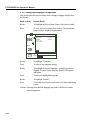
3.10.8 Setting Modem Parameters
This section describes the procedure used to establish the correct modem settings for proper operation. These settings control the operation of the external
modem.
Knob Activity
Desired Result
Rotate
To highlight the Communications Frame with a heavy
border.
Press
To view the Communications menu (shown below).
U/S 1
Communications Menu
150
Modem Initialization
Modem Number To
Data Transfer
Recorder Speed
Paper Style
Paper Vendor
High Speed Print
(none)
(none)
(1 cm/min)
(International)
(Analogic)
TOCO
20
(5)
Return
3 cm
min.
Jane Doe 194848
16:34:12
2/14/96
Rotate
To highlight “Modem Initialization.”
Press
To select “Modem Initialization” for editing.
Rotate
To highlight the desired character.
Press
To select this character for editing.
Rotate
To choose a new value for this character.
Press
To keep the new value for this character.
Repeat the previous four steps until the initialization string
has the desired changes.
Rotate
To highlight “OK.”
Press
To exit the modem initialization dialog box and return to
the Communications Menu.
Repeat the previous steps to set the “Modem Number to
Dial.”
Rotate
To highlight “Return.”
Press
To exit the Service Menu and return to the main monitoring
screen.
3-17
FETALGARD Lite Operator’s Manual
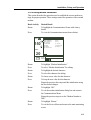
3.10.9 Setting Recorder Parameters
This section describes the procedure used to set the paper speed, paper vendor,
and paper style.
Knob Activity
Desired Result
Rotate
To highlight the Communications Frame with a heavy
border.
Press
To display the communications Menu shown below.
U/S 1
Communications Menu
150
Modem Initialization
Modem Number To
Data Transfer
Recorder Speed
Paper Style
Paper Vendor
High Speed Print
(none)
(none)
(1 cm/min)
(International)
(Analogic)
TOCO
20
(5)
Return
3 cm
min.
Jane Doe 194848
16:34:12
2/14/96
Rotate
To highlight “Recorder Speed,” “Recorder Paper Style,” or
“Recorder Paper Vendor.”
Press
To select the highlighted parameter for editing.
A dialog box will appear with the available options for this
parameter.
Rotate
To highlight the desired value.
The list below shows the values that are available for each
parameter.
{1 cm/minute,
Recorder speed
2 cm/minute,
3 cm/minute}
Recorder paper style
{U.S., International}
Recorder paper vendor {Analogic, Coro, HP}
Press
To keep the highlighted value and exit the dialog box.
Repeat the previous steps until “Recorder Speed,”Recorder
Paper Style,” and “Recorder Paper Vendor” are properly configured.
3-18
Rotate
To highlight “Return” in the Service Menu.
Press
To exit the Service Menu and return to the main monitoring
screen.
Installation, Setup, and Operation
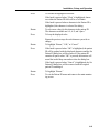
3.10.10 Understanding and Setting Alarms
The FETALGARD Lite monitor has the capability to alert the caregiver in the
event a heart rate goes above or below an alarm limit for a preset time delay.
The limit values and the delay from onset to alert are configurable. An alarm
event results in an audible tone and blinking of the heart rate value on the display. Pressing the speaker key on the monitor’s keypad can silence the alarm
tone. The blinking heart rate will continue as long the alarm condition persists
or until alarms are disabled.
The monitor also has the capability of alerting the clinician if a loss of heart
rate detection occurs. This alert occurs if a valid heart rate is followed by no
measurable heart rate for a preset time delay. The heart rate frame will display
blinking dashes and the audible warning tone will sound if this condition happens. The audible warning tone can be silenced by pressing the speaker button
on the monitor’s keypad. The display of blinking dashes will continue as long
as the alarm condition persists or until alarms are disabled. The loss of heart
rate alarm delay time is adjustable by the user.
Alarms are enabled or disabled by accessing the selection in the Ultrasound
menu. If alarms are disabled then all alarms are off. If alarms are enabled then
all alarms are on.
The following section describes the procedure used to set alarm parameters for
ultrasound heart rates.
Knob Activity
Desired Result
Rotate
To highlight the Ultrasound Frame with a heavy border.
Press
To view the Ultrasound menu (shown below).
U/S 1
Ultrasound Menu
150
Trace Separation
FHR Upper Limit
FHR Lower Limit
FHR Alarm Delay
Loss of FHR Delay
Alarm Status
(0 bpm)
(120 bpm)
(60 bpm)
(15 seconds)
(120 seconds)
(Disable)
TOCO
20
Return
(5)
3
cm/min
Jane Doe 194848
16:34:12
2/14/96
3-19
FETALGARD Lite Operator’s Manual
Rotate
To highlight “Heart Rate Upper Limit,” “Heart Rate Lower
Limit,” “Heart Rate Alarm Delay,” or “Loss of Heart Rate
Delay.”
Press
To select the highlighted parameter for editing.
A dialog box will appear with the available options for this
parameter.
Rotate
To highlight the desired value.
The list below shows the values that are available for each
parameter.
Heart Rate Upper Limit {120–220 BPM, 5 BPM increments}
Heart Rate Lower Limit {60–120 BPM, 5 BPM increments}
Heart Rate Alarm Delay {15–120 sec., 15 sec. increments}
Loss of Heart Rate Delay {30–120 sec., 30 sec. increments}
Press
To keep the highlighted value and exit the dialog box.
Repeat the previous steps until “Heart Rate Upper Limit,”
Heart Rate Lower Limit,” “Heart Rate Alarm Delay,” or “Loss
of Heart Rate Delay” are properly configured.
Rotate
To highlight “Alarm Status.”
Press
To select “Alarm Status” for a new setting.
Rotate
To highlight “Enabled,” or “Disabled.”
“Enabled” activates the alarm system, “Disable” deactivates
the alarm system.
Press
To keep the highlighted selection.
Rotate
To highlight “Return.”
Press
To exit the Ultrasound Menu and return to the main monitoring screen.
3.10.11 Adjusting the Display Contrast
Display contrast is set to a default value at the factory. This setting is
adjustable to optimize the display for best viewing. The contrast button and
the control knob are used for this adjustment.
Pressing the contrast button initiates the process and resets the contrast to the
factory default. This is done to ensure the display contrast is centered and the
display is reasonably viewable. The knob is rotated clockwise to lighten the
contrast or counterclockwise to darken the contrast.
3-20
Installation, Setup, and Operation
Pressing the contrast button a second time completes the adjustment process.
The new contrast setting is saved until the next time it is changed. Knob inactivity for more than 10 seconds will also complete the adjustment process as if
the button were pressed a second time.
3.10.12 Adjusting Speaker Volume
Speaker volume can be increased or decreased by pressing the speaker volume
button followed by clockwise or counterclockwise rotation of the knob. This
volume adjustment affects only the amplitude of the ultrasound heart sounds.
A volume icon, located in the ultrasound heart rate frame of the display,
changes with knob rotations to provide visual feedback of the volume setting.
Pressing the volume button a second time completes the adjustment process.
The new volume setting is saved until the next time it is changed. Knob inactivity for more than 10 seconds also completes the adjustment process.
The adjustment process varies slightly for a monitor with two ultrasound
channels. The first press of the volume button followed by knob rotation
adjusts the volume for ultrasound channel one. The second press of the volume button completes the adjustment for channel one and enables the adjustment of channel two. Knob rotation will now change the volume setting for
ultrasound channel two. A volume indicator icon for channel two, located in
the heart rate frame for channel two, operates the same as described above for
channel one. Pressing the volume button a third time completes the adjustment
process for channel two and saves the desired setting. Knob inactivity for
more than 10 seconds also completes the adjustment process.
3.11
FETALGARD Lite Recorder
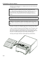
3.11.1 Installation and Loading Paper
Unpack the recorder and accessories and place the recorder on a solid table
surface. Connect the communications cable to the connector on the rear of the
recorder. The other end of the cable connects to its mating connector on the
rear of the monitor.
3-21
FETALGARD Lite Operator’s Manual
Attach the AC line cord to the IEC receptacle on the rear of the recorder and
to an appropriate AC outlet.
WARNING: The power receptacle must be a three-wire grounded outlet.
Never adapt the three-prong plug from the Battery Eliminator or accessory to
fit a two-slot outlet. If the outlet has only two slots, make sure that it is
replaced with a three-slot grounded outlet before attempting to operate the
recorder.
WARNING: Do not connect to an electrical outlet controlled by a wall switch.
WARNING: Do not attempt to connect or disconnect a power cord with wet
hands. Make certain that your hands are clean and dry before touching a power
cord.
The paper is loaded by first sliding the paper drawer forward as shown below.
A spacer is required in the paper tray when HP paper is used. This spacer is supplied with the monitor and is installed into the left side of the paper tray. This
spacer must be installed to properly align the paper to the print head. Make sure
this spacer is installed properly prior to proceeding with loading paper.
Unwrap a pack of paper and slide it into the paper tray as shown below.
3-22
Installation, Setup, and Operation
Several pages from the top of the pack of paper should drape forward over the
top of the paper drawer. The orientation of the paper is with the printed grid
facing up (unfolding from the top of the pack) and the TOCO grid area closest
to the recorder keypad.
Slide the paper drawer into the recorder. The recorder is now ready for use.
Turn the recorder on using the AC mains switch on the rear of the recorder.
An indicator LED on the front of the recorder will confirm the unit is attached
to an AC source and the unit is powered on.
3.11.2 Controls and Indicators
This section describes the fixed function buttons and indicator lights on the
recorder.
Icon
Description
Paper Advance button — This button is used to fast-forward the
recorder paper. A press and hold of this button will advance the
recorder paper at high speed until the button is released. The
recorder will resume its original activity when the button is released.
Any text and graphics in the process of being printed during a paper
advance event will be lost. When the button is released, printing will
resume normally.
Printing Enable/Disable button — A single press and release of
this button will toggle the recorder mode between printing and nonprinting. The indicator LED next to the icon at the left will be on
when printing is enabled and off when disabled.
At power-on, the unit will default to printing enabled. If the recorder
is connected to an active monitor, the recorder will automatically
begin printing as instructed by the monitor.
Power-on Indicator — This indicator will be on whenever the unit
is connected to an AC line source and the AC mains switch on the
rear of the recorder is on.
3-23
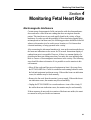
Monitoring Fetal Heart Rate
Section 4
Monitoring Fetal Heart Rate
Electromagnetic Interference
Certain strong electromagnetic fields can interfere with the ultrasound transducer and cause a false heart rate reading that does not originate from the
patient. This interference is rare, and usually found in the vicinity of large
machinery. In order to avoid the possibility of these interfering signals being
misinterpreted as fetal heart rates, the following procedure should be followed
whenever the monitor is to be used in a new location, or if it is known that
electrical machinery is being operated in the vicinity.
After connecting the ultrasound transducer(s), turn on the monitor and observe
the heart rate indications on the screen for 30 seconds. Intermittent display of
random heart rates is acceptable. However, if there is a constant display of a
physiological heart rate lasting more than 5 seconds, this is an indication that
there is a source of electromagnetic interference in the vicinity. The following
steps should be taken to determine if it is possible to use the monitor in this
environment.
• Move all line cords and line-powered equipment at least 6 feet away from
the FETALGARD Lite. Check for extension cords running behind or under
the bed and equipment in adjacent rooms. If the artifact heart rate indication
ceases, the monitor may be used normally.
• Remove the line cord from the monitor’s power supply. If the artifact heart
rate indication ceases, the monitor may be used normally.
• Unplug the FETALGARD Lite recorder and move it out of the vicinity. If
the artifact heart rate indication ceases, the monitor may be used normally.
If these measures do not result in cessation of the heart rate artifact, the monitor cannot be safely used in this environment.
4-1
FETALGARD Lite Operator’s Manual
Fetal heart rate is measured by placing an ultrasound transducer on the maternal abdomen and processing the Doppler echo signal to produce a heart rate
and an audio representation of the echo signal.
Step 1: Preparing the Monitor
Turn the monitor on and verify that the normal monitoring screen appears on
the display. Remove the monitor from service if an error occurs.
Determine whether the monitor is powered from the internal battery or the battery eliminator. If operating on the internal battery, check the power status
frame on the display to determine whether the battery has sufficient charge to
complete the monitoring session. Use the battery eliminator if the battery is
too low.
Check the ultrasound transducer to verify proper attachment to the monitor.
For twins monitoring, make sure the second ultrasound transducer is properly
connected.
Adjust heart rate channel one speaker volume to mid level. Adjust channel
two speaker volume to off if monitoring twins.
Apply ultrasound gel to the face of the transducer.
Step 2: Acquiring the Fetal Heart Signal
Determine the location of the fetal heart using palpation or a fetoscope.
Place the transducer on the maternal abdomen and listen for the fetal heart signal. Reposition the transducer for the loudest fetal heart signal and verify the
indicator LED on the transducer is blinking at the fetal heart rate.
Secure the ultrasound transducer with the elastic belt. Make sure the transducer is still positioned for the loudest fetal heart signal.
Verify the monitor is displaying fetal heart rate values and that the heart rate
indicator on the ultrasound transducer is blinking at the measured heart rate.
Step 3: Acquiring Twins’ Heart Rates
Follow the steps outlined in step 2 above to acquire the heart rate for the first
fetus.
Adjust the ultrasound audio volume for channel one down and channel two up
so that the second heart sounds can be heard.
Determine the location of the second fetal signal using palpation or fetoscope.
4-2
Monitoring Fetal Heart Rate
Apply gel to the second ultrasound transducer and place it on the maternal
abdomen where the second fetal signal was located. Adjust the position of the
transducer to find the fetal signal and to maximize its loudness.
Secure the ultrasound transducer with the elastic belt. Make sure the transducer is still positioned for the loudest fetal heart signal. Also verify the position
of transducer one has not changed.
Verify the monitor is displaying fetal heart rate values for both fetuses and that
the heart rate indicators in both ultrasound transducers are blinking at the measured heart rate.
Step 4: Monitor Adjustments
Readjust the volume settings for the desired loudness.
4-3
Monitoring Uterine Activity (UA)
Section 5
Monitoring Uterine Activity (UA)
Uterine activity is measured externally by placing a pressure sensitive device
(Tocotonometer) on the maternal abdomen and recording relative pressure
changes.
Step 1: Preparing the Monitor
Turn the monitor on and verify that the normal monitoring screen appears on
the display. Remove the monitor from service if an error occurs.
Determine whether the monitor is powered from the internal battery or the battery eliminator. If operating on the internal battery, check the power status
frame on the display to determine whether the battery has sufficient charge to
complete the monitoring session. Use the battery eliminator if the battery is
too low.
Check the TOCO transducer to verify proper attachment to the monitor.
Check for the proper setting for TOCO baseline. Adjust as needed.
Step 2: Acquiring Uterine Activity Data
Place the face (button side) of the Tocotonometer on the fundus of the uterus
when contractions are not occurring. No gel is required.
Secure the Tocotonometer with the belt. The uterine activity reading at this
point should be greater than 30 and less than 90 units. If the readings fall outside this range, the belt may be too tight or too loose. If the belt is over tightened, the contraction peaks may have a flat-top at less than 100 on the TOCO
scale. If the belt is under tightened, the position of the transducer may wander
and cause unusable readings. Readjust the belt pressure as needed.
Step 3: Monitor Adjustments
Press the TOCO Zero button on the front panel to adjust the values to the
baseline. This must be done during non-contraction intervals.
5-1
Remote Patient Marker and Clinician Marker
Section 6
Remote Patient Marker and
Clinician Marker
6.1
Clinician Marker
The nurse’s marker arrow is provided so that the nurse can record the time of
important events. The clinician merely presses the marker button located on
the front-panel keypad at the time an event occurs. This marker time is recorded in the patient record in the monitor.
The nurse marker icon is a downward pointing arrow. The monitor will display this downward pointing arrow in the information frame of the display. A
strip chart printout of the patient record will also show this mark accompanied
by the time and date.
6.2
Remote Patient Marker
The patient marker arrow is provided so that the patient can record the time of
important events. The patient merely presses the marker button located on the
end of the marker cable at the time an event occurs. This marker time is
recorded in the patient record in the monitor.
The patient marker icon is an upward pointing arrow. The monitor will display
this upward pointing arrow in the information frame of the display. A strip
chart printout of the patient record will also show this mark.
6-1
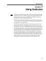
Using Graticules
Section 7
Using Graticules
Graticules are reference lines on a chart that are used to aid in interpreting the
plotted data. The FETALGARD Lite has two horizontal graticule lines in the
ultrasound trend frame located at 120 BPM and 160 BPM. These graticule
lines provide a reference for estimating heart rate.
The TOCO trend frame also has a graticule reference line. It is located at the
TOCO baseline value. This graticule line is relocated when the baseline value
is changed to one of the other values.
When the operator presses the graticule button on the keypad, the two reference graticule lines in the ultrasound trend frame are replaced with two new
graticule lines. These lines are 15 BPM apart and can be moved up and down
by rotating the control knob. This pair of moveable graticule lines will stay on
the screen until there is 20 seconds of knob inactivity at which point they will
change back to the fixed lines at 120 BPM and 160 BPM. The purpose for
these moveable graticule lines is to aid in establishing heart rate variability,
particularly when performing a non-stress test, NST. For example, the lower
line can be placed on a reference heart rate baseline and the other line used to
locate the reference point where the heart rate change equaled 15 BPM.
Timing marks are spaced 1 minute apart to provide a simple time scale.
7-1
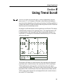
Using Trend Scroll
Section 8
Using Trend Scroll
The FETALGARD Lite can store up to 12 hours of patient data. Only the
most recent 6, 12, or 18 minutes of this data is observable on the display at
any point in time (depending on the print speed setting). Scrolling capability is
a feature that enables viewing stored data from the present session or historical
data from previous monitoring sessions.
Pressing the scroll-mode button on the keypad enters scroll mode. This button
is labeled with an image of two opposing arrows. Two opposing arrows will
be displayed above the ultrasound trend frame indicating the monitor is in
scroll mode. A second press of this button or knob inactivity for 30 seconds
will exit scroll mode.
U/S 1
240
150
160
TOCO
30
100
20
150
120
(5)
0
3
cm/min
3
Jane Doe 194848
16:30:12
2/14/96
The monitor will display a vertical reference line centered in the ultrasound
trend frame and a vertical reference line centered in the TOCO trend frame.
TOCO and heart rate values pass the vertical reference line as the data is
scrolled through the display. The heart rate values at the reference line are displayed above the vertical reference line in the ultrasound trend frame and the
TOCO values at the reference line are displayed below the vertical reference
line in the TOCO trend frame.
8-1
FETALGARD Lite Operator’s Manual
The heart rate numeric frames, TOCO numeric frame, power status frame, and
the communications frame are unaffected when in scroll mode and continue
displaying the most current data and status information pertinent to the present
monitoring session.
The patient ID frame displays the appropriate ID for the stored data. The ID
will be for the current patient when scrolling through the data from the current
monitoring session. When scrolling further back into previous records, the displayed ID will reflect the record being viewed. The Patient ID will change
after the present record has scrolled fully off the display and the next record
begins to scroll onto the display.
The time and date frame will display the time and date when the data values
were recorded as they pass the vertical reference lines.
Rotating the control knob slides the heart rate and TOCO values synchronously left and right. Clockwise rotation views older data and counterclockwise
rotation views more recent data. Rotating the knob slowly slides the values
through the display at the rate that is convenient for viewing. Rotating the
knob quickly slides the data through the display at a faster rate. This provides
a quicker way to move ahead or back.
8-2
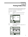
Printing Patient Files
Section 9
Printing Patient Files
This section describes the procedure used to print stored patient files. Printing
stored files occurs at a faster rate than printing during a monitoring session
and is referred to as “batch printing” or “high speed printing.”
Knob Activity
Desired Result
Rotate
To highlight the Communications Frame with a heavy
border.
Press
To view the Communications menu (shown below).
U/S 1
Communications Menu
150
Modem Initialization
Modem Number To
Data Transfer
Recorder Speed
Paper Style
Paper Vendor
High Speed Print
(none)
(none)
(1 cm/min)
(International)
(Analogic)
TOCO
20
Return
(5)
3 cm
min.
Jane Doe 194848
16:34:12
2/14/96
Rotate
To highlight “High Speed Print.”
Press
To select “High Speed Print.” The “High Speed Print” dialog box will appear.
U/S 1
Communications Menu
Modem Initialization
(none)
Modem Number To
(none)
Data Transfer
R e High Speed Print
Pap
No printer attached!
Pap
High
OK
150
TOCO
20
(5)
Return
3
cm/min
Jane Doe 194848
16:34:12
2/14/96
9-1
FETALGARD Lite Operator’s Manual
The most recent patient file is shown at the top of the dialog
box as the first choice for printing.
Rotate
To highlight “Yes,” “No,” “All,” or “Cancel.”
Press
To select “Yes,” “No,” “All,” or “Cancel.”
File prints with % complete status message. Selecting
“Yes” will cause the patient file shown to be printed and the
next patient file to be displayed.
Selecting “No” will result in not printing of the displayed
file and the next patient file to be displayed.
Selecting “All” causes all stored patient files to be printed.
Selecting “Cancel” closes the dialog box and returns to the
Communications menu.
Repeat the selection process until all desired patient files
have been chosen for printing.
Rotate
To highlight “Cancel.”
Press
To select “Cancel” and close the dialog box.
Rotate
To highlight “Return.”
Press
To exit the Communications menu and return to the main
monitoring screen.
High speed printing of the patient files will occur at a rate of approximately 30
cm per minute until all selected files have been printed.
9-2
Transferring Patient Data
Section 10
Transferring Patient Data
In order to transfer patient data files from the monitor to a remote computer,
the monitor must be configured with the correct modem setup string and dialing phone number (see the chapter entitled Installation, Setup, and Operation
for details). Additionally, the remote computer must have a modem installed
and be running the FETALGARD Lite View applications program.
Installation and operation of FETALGARD Lite View is discussed in another
chapter within this operator’s manual.
The user must purchase an approved modem in order for file transfers to work
properly. Please contact the factory for the list of approved modem vendors
and model numbers. Follow the installation procedure supplied by the modem
vendor prior to connecting to the FETALGARD Lite monitor.
The communications port on the rear of the monitor is connected to a tabletop
modem using an RS-232 cable with a female DB9 connector and a male DB25
connector. The cable supplied with the FETALGARD Lite Recorder will work.
CAUTION: General-purpose personal computers and modems are not designed
to meet the electrical safety requirements of medical devices. The RS-232 connector on the FETALGARD Lite is electrically isolated to permit safe connections to non-medical devices, which should be connected with a cable of sufficient length to prevent the non-medical equipment from contacting the patient.
Make sure the cable is attached properly and the connectors are fully engaged.
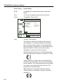
The monitor will display the telephone icon shown below when properly
attached to a modem.
The following section describes the procedure used at the monitor to complete
a transfer of all patient records in the monitor to a remote computer. Make
sure the remote PC is properly configured and running the FETALGARD Lite
View application program before starting.
When connecting the monitor directly to a computer, use a null modem PC
cable no longer than 3 meters in length having a female DB9 connector at
both ends. The conductor shield must be tied to the metal shells of the DB
connectors.
10-1
FETALGARD Lite Operator’s Manual
Knob Activity
Desired Result
Rotate
To highlight the Communications frame with a heavy
border.
Press
To view the Communications menu (shown below).
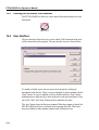
Rotate
To highlight “Transfer Data.”
U/S 1
Communications Menu
150
Modem Initialization
Modem Number To
Data Transfer
Recorder Speed
Paper Style
Paper Vendor
High Speed Print
(none)
(none)
(1 cm/min)
(International)
(Analogic)
TOCO
20
(5)
Return
3 cm
min.
Press
Jane Doe 194848
16:34:12
2/14/96
To select “Data Transfer.”
The dialog box will show the dialing number and commence dialing. You will hear the dial tone and dialing
process from the modem speaker. The Communications
frame will display a two-phone icon with one dark and one
light (shown below). This icon means the monitor is
attempting to connect to the remote computer.
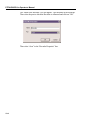
Transferring patient data files occurs automatically when
the monitor and remote computer are connected. The Data
Transfer dialog box will show the record number being
transferred, the total number of files to be transferred, and
percent complete. The Communications frame will display
a two-phone icon with both dark (shown below). This
means files are being transferred.
When all files have successfully transferred the Data
Transfer dialog box will display a message confirming
completion.
10-2
Transferring Patient Data
10.1
Press
To exit the Data Transfer dialog box and display the
Communications menu.
Rotate
To highlight “Return.”
Press
To exit the Communications menu and return to the main
monitoring screen.
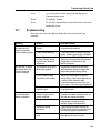
Troubleshooting
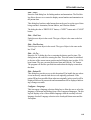
Here are some comments that may help when the process doesn’t go
smoothly.
Behavior
Reason
Possible Remedy
The monitor dialed
a number but did
make a connection
to the remote computer.
Remote Modem did not
answer.
Check that the remote modem is
connected and turned on.
Dialed number was busy.
Check the number by calling using the
phone. Wait for current call to complete.
Remote Modem connected
but Data Transfer timed
out before any data was
transferred.
Check that the FETALGARD View
Receiver is running and that the modem
is selected to receive data on the
remote computer.
The modem may be set to
disable the speaker.
Examine the modem documentation
and initialization strings to enable the
the modem speaker during dialing.
Faulty modem or faulty
connection to the modem.
Watch the modem lights for activity
during dialing. If the modem lights show
no activity then check the cable
connections between the monitor and
the modem. Check the modem operation.
Modem not connected to
the phone jack.
Check the modem connection to the
to the phone jack.
Disconnect from modem or
phone line @ monitor or
remote computer.
Check the phone line connections
between the modem and phone jack on
the local and remote computers.
Poor phone connection.
Check the phone connection. Poor or
noisy phone lines will cause the
transfer of data to be terminated.
Insufficient remote
processor.
Check that the computer running the
FETALGARD Receiver software meets
the minimum system requirements.
Extension was taken off
hook.
Check that another extension on the
same phone line was not used.
No dial tone or dialing
was heard when the
monitor dialed the
remote computer.
File transfers were
cut off/terminated
before completion.
10-3
FETALGARD Lite View
Section 11
FETALGARD Lite View
11.1
Overview
FETALGARD Lite View is an application program that is used to view, annotate, and store patient data files originating from the FETALGARD Lite monitor. The program runs on a personal computer with either Windows 95/98™
or WindowsNT™ operating systems.
Patient data files are transferred to the computer using either a serial port
hook-up between the monitor and computer or via a modem connection.
The program uses a Windows-like user interface with pull-down menus and
mouse operation.
11.2
Installation
System Requirements:
• IBM-compatible personal computer
• Standard VGA graphics
• CD-ROM drive
• 2 megabytes (minimum) available hard drive free space
• Windows 95, 98 or NT operating system
Procedure
• Insert View CD in the CD-ROM drive.
• Follow the on-screen instructions.
• The View program will be installed in the default directory or in one selected
by the operator during the installation process.
• The Help Files are supplied in Adobe Acrobat pdf format. To access these
files, the system needs Adobe Acrobat Reader which is available at
www.adobe.com. This is free of charge.
11-1
FETALGARD Lite Operator’s Manual
• In order to install FETALGARD Lite View, administrative rights to the system are needed. If an error message is displayed during the installation
process, contact the system administrator.
11.3
Starting FETALGARD Lite View
Running the View program is accomplished by clicking on the “Viewer” contained in the Program selection of the Start menu.
11.4
Display Screen
The picture below shows the FETALGARD Lite View program with a patient
record open. The Main menu selections are shown at the top of the screen.
Each patient file is identified at the top of the window by its file name and
location. The patient data is displayed in a format similar to the strip chart
printout from the recorder. All graphical data and text information is included.
Annotations made within the View program are displayed in the bottom section of the window.
Elevator controls are used to scroll left and right, or up and down to view the
desired section of the patient record.
11-2
FETALGARD Lite View
11.5
Menu System
The main menu system contains the following selections:
File…Open…
Starts the dialog box used for opening patient records. This dialog shows a
multi-column list box containing all of the records in the currently selected
FETALGARD Lite Viewer database. Patient ID, start time, duration, and
monitor serial number are shown for each file.
The records can be sorted (ascending or descending) by any of the headings
by clicking on the heading.
The user can select one or more records in the list box by left clicking on it,
select a group of records with Shift-Left click, or select/de-select a record with
Control-Left-click.
The “…” button allows the user to select another database via a Windows
File dialog box. The user can select a file and then click Open.
File…Close
Closes the window containing the currently active patient data.
File…Delete…
Starts the dialog used for deleting patient records. This menu entry provides a
mechanism for removing all records corresponding to a specific patient from
the currently selected database. Deletes are final. There will be no way to
undelete.
The File Delete dialog will list all patients in the currently selected database.
Entries will be sorted alphabetically by user ID.
The user would initiate the file delete by selecting a patient name and clicking
the “DELETE” button.
If the user tries to delete patient records which have not been backed up, then the
application will inform the user of this and allow the operation to be cancelled.
File…Backup…
Starts the dialog used for storing patient records to other media. This menu
entry provides a mechanism for copying all records corresponding to one or
more patients to backup media such as a zip drive.
The File Backup dialog will list all patients in the currently selected database.
Entries will be sorted alphabetically by user ID.
11-3
FETALGARD Lite Operator’s Manual
The user must select a destination file. If the destination file already exists
then the user will be prompted to overwrite the file.
The user would initiate the file archive by selecting one or more patient IDs
and clicking the “BACKUP” button.
File…Page Setup…
The page setup dialog enables the user to specify the display format.
The user can select from Analogic, HP or Corometrics style paper, U.S. or
International format, and print speed (1, 2 or 3 cm/min.).
To change the display format, the user must select one of the six paper types
or one of the print speeds from the pull-down menu.
File…Print…
This will bring up the standard Windows print dialog for selecting the printer.
By default, the printed output will be the entire trend data set. The user can
choose to print just the highlighted portion by clicking on “Selection” in the
Print Menu. If a FETALGARD Lite Recorder has been installed, it will appear
as an option.
Note: Original chart paper numbers will not coincide with FETALGARD Lite
Viewer numbers.
File…Purge FGLite Recorder
This will cancel the current printing job. (Note: The Recorder will finish with
a few pages of blank paper.)
File…Exit
Ends the program.
Edit…Annotate…
Starts the Enter Annotation dialog. The Edit Menu provides tools for annotating the patient record and for searching within the patient record. The user can
add annotations, search for markers and annotations, jump to specific times
during the test and change the patient ID to fix data entry errors.
When Annotate is selected, an annotation marker (a circled number) will be
superimposed on the patient data to show the location of the annotation. It will
show who made the annotation and when it was made. To enter the annotation, the user must type their annotation text and click OK.
Annotations are stored immediately and cannot be deleted or modified.
11-4
FETALGARD Lite View
Edit…Find…
Starts the Find dialog box for finding markers and annotations. The Find dialog allows the user to re-center the display around markers and annotations in
the patient data.
This dialog box has three radio buttons that can be used to set the type of data
being searched: Annotation, Patient Marker, and Clinician Marker.
The dialog box has a “PREVIOUS” button, a “NEXT” button and a “CLOSE”
button.
Edit… Find Next
Finds the next object in the record. The type of object is the same as the last
“Find.”
Edit…Find Previous
Finds the previous object in the record. The type of object is the same as the
last “Find.”
Edit… Go To…
Starts the Go To dialog box for re-centering the data to specific times. The
dialog has an edit control for entering the time. This edit control is initialized
to the time of the current cursor position and will display time in either 12/24hour format. The user can enter the desired time and click the “Go” button.
The program will find the specified time and redraw the display centered on
that data.
Edit…Patient ID
This dialog box provides a way to edit the patient ID to handle the case where
it was incorrectly entered when the test was originally performed. If the
patient ID has been modified from what was originally in the record it will be
displayed followed by an asterisk and an annotation will be displayed indicating a change was made.
Configure…Language
This item opens a language selection dialog box to allow the user to select the
language of all menus and dialogs from a list of supported languages. The dialog box displays a list of the available languages with the currently selected
language checked. Language selection is the fourth pull-down menu and the
first option.
11-5
FETALGARD Lite Operator’s Manual
Configure…Add Patient Records to…
When new patient records are transferred from a monitor to the PC, they will
be added to the database file specified in this dialog box. If the file does not
exist, FETALGARD Lite Viewer will create it.
Once specified, the name of this database will appear in the lower right corner
of the FETALGARD Lite Viewer screen.
Configure…Time Format
This menu entry allows the user to set the time and date formats for the application. Choices for time format are 12 hour or 24 hour. Choices for date format are MM/DD/YY or DD/MM/YY.
Utility…Database Compact
Compacts the database. This command is used to remove deleted files from
the database and compact the database to the smallest size possible.
Utility…Database Repair
Repairs a corrupted database.
Window…Tile
Splits the data window so that two or more records can be viewed
simultaneously.
Window…Cascade
Cascade the windows so that one patient record dominates the window and the
top window mostly obstructs other open patient records.
Window… “Patient ID”
Allows the user to switch between opened patient files by selecting the
“Patient ID” of interest.
Help…FETALGARD Lite Viewer Help
Starts the help subsystem.
Help…Contact Info
Phone number and email address for tech support.
Help…About…
This menu entry will display a dialog containing revision and copyright
information.
11-6
FETALGARD Lite Receiver and Recorder
Section 12
FETALGARD Lite Receiver and
Recorder
12.1
Overview
The FETALGARD Lite Receiver is a Windows application that is used to
transfer data from the FETALGARD Lite monitor to a database on a PC. The
Receiver runs as an application on Windows 95/98 or Windows NT. An icon
representing the FETALGARD Lite Receiver will appear in the System Tray.
This program must be installed on the computer which has the patient data
base files. This can be the same computer that has the FETALGARD Lite
View program or a separate computer.
The FETALGARD Lite Recorder program is a Windows application for
adding the FETALGARD Lite Recorder to the printer menu. This enables the
FETALGARD Lite Viewer user to print to the FETALGARD Lite Recorder.
12.2
Installation
System Requirements:
• IBM-compatible personal computer (200 MHz Pentium or equivalent)
• Standard VGA graphics
• CD-ROM drive
• 2 megabytes (minimum) available hard drive free space
• Windows 95, 98, or NT operating systems
Procedure:
• All applications will be installed when FETALGARD Lite Viewer is
installed.
• The Receiver program will be installed in the default directory or in one
selected by the operator during the installation process.
• The Recorder program will be installed in the system folder.
12-1
FETALGARD Lite Operator’s Manual
12.3
Starting FETALGARD Lite Receiver
The FETALGARD Lite Receiver can be started from the desktop icon or the
Start menu.
12.4
User Interface
The user interface allows the user to select which TAPI communication ports
will be answered by this program. The user interface screen is shown below.
To enable or disable a port, the user must select the port by clicking its
description in the list box. Then, if a port is disabled, it can be enabled with the
“Start” button. If a port is enabled, it can be disabled with the “Stop” button.
Enabled ports are indicated by a check mark next to the port description. Only
one of the “Start” and “Stop” buttons will be enabled at any time.
The “quit” button closes the Receiver program. When the program is closed, the
FETALGARD Lite Receiver will answer no incoming data calls. This leaves
the port available for other modem transfers such as Internet access.
12-2
FETALGARD Lite Receiver and Recorder
If the user clicks the Statistics button while a port is selected, the statistics summary will be shown for that port. The statistics screen is shown below.
12.5
Installation of the Recorder
Adding the FETALGARD Lite Recorder to the printer menu is accomplished
by running the FETALGARD Lite Recorder program.
Select the FETALGARD Lite Recorder icon in the Control Panel. The
Control Panel is found by using the start button and the settings menu. The
“Recorder Properties” box will appear and click on “Add.”
12-3
FETALGARD Lite Operator’s Manual
The “Install New Recorder” box will appear. Type the name of the Recorder.
Then select the port to which the Recorder is connected and click on “OK.”
Then select “close” in the “Recorder Properties” box.
12-4
Cleaning
Section 13
Cleaning
This chapter contains instructions for the care and cleaning of the FETALGARD Lite unit and its accessories.
The FETALGARD Lite requires proper care and preventive maintenance.
This ensures consistent operation and maintains the high level of performance
necessary in monitoring procedures.
13.1
Monitor
Keep the external surface clean and free of dust, dirt, and residual liquids.
Clean with a damp cloth using mild soap and water or hospital approved, nonabrasive disinfectants.
WARNING: Unplug the monitor from the AC power source and detach all
accessories before cleaning. Do not immerse the unit in water or allow liquids
to enter the case.
CAUTION: Take extra care when cleaning the display surfaces, which are
sensitive to rough handling. Rub the lens that covers them with a soft, dry
cloth.
13.2
Recorder
Maximum time between printhead cleaning is one year, more frequent cleaning may be required depending on operating environments.
WARNING: Unplug the recorder from the AC power source and detach all
accessories before cleaning. Do not immerse the unit in water or allow liquids
to enter the case.
13-1
FETALGARD Lite Operator’s Manual
To clean, wipe the printhead and roller with a Q-tip soaked in isopropyl alcohol while lifting the head, or run 6" x 6" cleaning paper pre-soaked in isopropyl alcohol through the recorder. Pre-saturated thermal printer cleaning
cards are available in boxes of 25 cards or in bulk. They may be ordered
directly from:
Clean Team Company™
960 Enchanted Way Building 108
Simi Valley, California 93065
Phone: 805-581-1000
Fax: 805-581-1058
13.3
Transducers
Cleaning and Disinfecting the Tocotonometer and Ultrasound
Transducer
To avoid damage to the transducers, clean and disinfect only according to the
following instructions. Care MUST be taken to preserve both the
Tocotonometer label and the Tocotonometer cable label. DO NOT remove,
conceal or deface Tocotonometer labels.
CAUTION: Do not autoclave. Do not gas sterilize.
1. Wipe the device with a sterile wipe soaked in enzymatic detergent safe for
use with metal instruments. Wipe the exterior of the device three times.
Prepare the detergent according to the manufacturer’s transducer recommendations.
2. Scrub the transducer with enzymatic detergent using soft bristled brush for
five (5) minutes. DO NOT IMMERSE THE TRANSDUCER.
CAUTION: Do not immerse in liquid. When using solutions, use sterile wipes
to avoid pouring fluids directly on the transducer.
3. Wipe the transducer three (3) times with sterile water to remove soap
residue.
4. Wipe the transducer with a sterile wipe soaked in Cidex™. Wipe all exterior surfaces of the transducer three (3) times.
13-2
Cleaning
5. Wipe the transducer three (3) times with sterile water to remove Cidex
residue.
6. Dry the device thoroughly with a sterile soft towel or gauze surgical sponge.
7. Wrap the dry device in a fresh sterile soft towel or transparent sterile wrap
for storage until next use.
13.4
Belts
Wash soiled belts with soap and water.
CAUTION: The water temperature must not exceed 60°C (140°F).
13-3
Specifications
Section 14
Specifications
FETALGARD Lite Monitor Specifications:
Physical Characteristics
Dimensions — 18 cm H x 24.2 cm W x 13 cm D
Weight — approx. 1.9 kg
Safety
Complies with EN60601-1, EN60601-1-1, En60601-2
Class II Equipment, double insulated
Continuous Operation
Type BF applied parts
Power
Internal:
External:
Lead-acid, rechargeable
2-hours operation fully charged at 10°C
14 hours to full recharge during monitoring
8 hours to full recharge when monitor is off.
AC-powered Battery Eliminator, two models:
P/N 21-615116, 100-120V~, 50-60 Hz, 0.15A
P/N 21-615115, 220-240V~, 50-60 Hz, 0.08A
Power Dissipation:
Battery-powered: 6 watts, maximum
AC-powered
10 watts, maximum
Environmental
Operating Temperature:
Storage Temperature:
Relative Humidity:
Altitude:
10°C to 45°C (50°F to 110°F)
–20°C to 60°C (–4°F to 140°F)
20% to 90% non-condensing
0—3048m (0—10,000 ft)
14-1
FETALGARD Lite Operator’s Manual
Doppler Ultrasound FHR Monitoring
Parameter
Value
I(SATA) at the transducer face: 0.766 mW/cm2 +27.8/–23.6%
Entrance beam dimensions:
19.95 cm2, circular
Ultrasonic frequency:
1024 MHz ±0.5%
Pulse duration:
97.65625 microseconds
Pulse repetition frequency:
3.2 kHz
Ultrasonic power:
15.28 mW +27.8/–23.6%
BPM Range:
USA Paper
50-240 BPM
International Paper
50-210 BPM
Accuracy:
±1% ±1 BPM
Leakage:
<10 µA @ 264 VAC applied to transducer
Isolation:
>4 kV RMS, Type BF applied part
Tocotonometer Uterine Activity (TOCO) Monitoring
Parameter
Value
TOCO Range:
0-100 relative units
Resolution:
1 Count
Accuracy:
±1% ±1 relative unit
Leakage:
<10 µA @ 264 VAC applied to transducer
Isolation:
>4 kV RMS, Type BF applied part
FETALGARD Lite Recorder Specifications:
Physical Characteristics
Dimensions — 11.5 cm H x 24.2 cm W x 20.4 cm D
Weight — approx. 3.4 kg
Safety
Complies with EN60601-1, EN60601-1-1, En60601-2
Class I Equipment, requires 3-prong outlet with protective earth
Continuous Operation
Power
100-120V~, 50-60 Hz, 0.4A
220-240V~, 50-60 Hz, 0.2A
Power consumption: 20 watts maximum at nominal supply voltage
Environmental
Operating Temperature:
Storage Temperature:
Relative Humidity:
Altitude:
14-2
10°C to 45°C (50°F to 110°F)
–20°C to 60°C (–29°F to 175°F)
20% to 90% non-condensing
0—3048m (0—10,000 ft)
Specifications
Paper
Pack Style:
Pack Size:
End-of-Pack:
Loading:
Paper Detectors:
Paper Speeds
Normal:
High-Speed:
Z-Fold. USA or International
152 mm x 90 mm
Mark along paper edge
Front-door, drop-in, self aligning
Paper Out
Loading Door Open
1, 2, and 3 cm/min ±1%
30 cm/min
Paper Tracking Accuracy: ±1% (exclusive of paper accuracy)
14-3
Troubleshooting and Maintenance
Section 15
Troubleshooting and Maintenance
15.1
Self Test
The monitor performs a self test each time the unit is turned on.
1. Make sure the recorder and monitor are properly interconnected.
2. Check the recorder for paper.
3. Connect the monitor to the battery eliminator.
4. Turn on the monitor and recorder.
Check that the monitor successfully powered on and is displaying the main
monitoring screen. If an error occurs the monitor will display the error screen.
The unit should be removed from service if this occurs.
Check that the recorder is feeding paper and the power on test pattern printed
properly. Remove from service if this does not occur.
15.2
Ultrasound Transducer Test
To test an ultrasound transducer:
1. Properly connect the transducer to the rear of the monitor.
2. Turn on the monitor and recorder.
3. Adjust the speaker volume to an audible level.
4. Hold the transducer on one hand and tap on the transducer face with the
other hand. The tapping should be heard from the monitor.
The transducer is operating properly if you can hear noise from the speaker.
Remove from service if no noise is heard or until the proper cause is identified
and repaired.
15-1
FETALGARD Lite Operator’s Manual
15.3
TOCO Test
To test the TOCO transducer:
1. Properly connect the transducer to the rear of the monitor.
2. Turn on the monitor and recorder.
3. Gently apply pressure to the button centered on the face of the transducer.
The display and printout should show a change in pressure if the transducer is
operating properly. Remove from service if this does not occur.
15.4
Battery Disposal and Handling
Caution when disposing of internal lead acid battery. Adhere to all applicable
laws regarding recycling. Avoid storing battery above 140°F. If clothing or
skin comes in contact with material from inside the battery, immediately wash
with plenty of clean water.
15.5
Maintenance
The FETALGARD Lite monitor, recorder and accessories require no periodic
calibration or adjustment.
The recommended interval for performing hipot and leakage testing is once
per year.
15-2
MedaSonics//®
a division of
CooperSurgical
15 Forest Parkway
Shelton, CT 06484
Tel: (800) 243-2974
Fax: (800) 262-0105
www.coopersurgical.com
16-400823 REV. 3