1
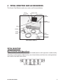
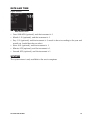
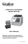
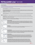
4077
EXTERNAL FETAL MONITOR
USER MANUAL
Important: Do not use the External Fetal Monitor without first reading
and understanding this manual! Save this manual for future use.
Federal Law (USA) restricts this device to sale by or on the order of a
physician. This product should not be used unless the operator has
been instructed by a qualified healthcare professional.
4077-INS-LAB-RevB09
CONTENTS
1
INTRODUCTION ...............................................................................................................................3
INTENDED USE OF THIS DEVICE....................................................................................................... 3
FEATURES .......................................................................................................................................... 3
2
SAFETY INFORMATION....................................................................................................................4
ULTRASOUND SAFETY GUIDE ........................................................................................................... 5
SAFETY PRECAUTIONS ..................................................................................................................... 5
DEFINITIONS AND SYMBOLS ............................................................................................................ 7
3
HANDLING ........................................................................................................................................8
GF HEALTH PRODUCTS, INC. FREIGHT POLICY ............................................................................... 8
UNPACKING........................................................................................................................................ 8
STORAGE ............................................................................................................................................ 8
4
FETAL MONITOR AND ACCESSORIES .............................................................................................9
FETAL MONITOR ................................................................................................................................ 9
ACCESSORIES (TRANSDUCERS AND CABLES) ............................................................................... 17
5
MENU DESCRIPTION .....................................................................................................................18
FUNCTION MENU ............................................................................................................................. 18
ALARM PARAMETER CONFIGURATION ........................................................................................... 19
FETAL MONITORING CONFIGURATION ........................................................................................... 21
PRINT CONFIGURATION .................................................................................................................. 22
AUTO MONITORING ......................................................................................................................... 22
DATE AND TIME ................................................................................................................................ 23
SYSTEM ............................................................................................................................................ 23
6
SETUP ............................................................................................................................................24
FETAL MONITOR CONNECTIONS..................................................................................................... 24
FETAL MONITOR PRINTER PAPER ................................................................................................... 24
TURNING ON THE FETAL MONITOR ................................................................................................ 25
CONNECTING TRANSDUCERS AND CABLES .................................................................................. 25
TURNING OFF THE FETAL MONITOR .............................................................................................. 25
7
FETAL MONITOR OPERATION .......................................................................................................26
ULTRASOUND MONITORING OF FHR .............................................................................................. 26
MONITORING UTERINE ACTIVITY (CONTRACTIONS) .................................................................... 27
REMOTE PATIENT MARKER RECORDING OF FETAL MOVEMENT .................................................. 28
AFTER MONITORING ........................................................................................................................ 28
8
MAINTENANCE, CARE AND CLEANING .........................................................................................29
PREVENTIVE MAINTENANCE .......................................................................................................... 29
CARE AND CLEANING OF MONITOR................................................................................................ 29
CARE AND CLEANING OF ACCESSORIES ........................................................................................ 30
STERILIZATION ................................................................................................................................ 32
DISINFECTION .................................................................................................................................. 32
CARE OF RECORD PAPER ................................................................................................................ 33
9
TROUBLESHOOTING ......................................................................................................................34
10 SPECIFICATIONS ...........................................................................................................................36
MONITOR .......................................................................................................................................... 36
TRANSDUCERS AND CABLES .......................................................................................................... 38
SIGNAL INPUT/OUTPUT CONNECTOR............................................................................................. 38
11 LIMITED WARRANTY .....................................................................................................................39
12 APPENDIX A, EC DECLARATION OF CONFORMITY ......................................................................41
13 INDEX .............................................................................................................................................42
Graham-Field and Grafco are registered trademarks of GF Health Products, Inc.
Packaging, warranties, products, and specifications are subject to change without notice.
GF Health Products, Inc. is not responsible for typographical errors.
4077-INS-LAB-RevB09
2
1
INTRODUCTION
This user manual contains important information and safety precautions for the Grafco
External Fetal Monitor. Before using the Fetal Monitor, please read and understand this
entire user manual. Take special note of all safety precautions that begin “DANGER” and
“WARNING”. Save this user manual for future reference.
INTENDED USE OF THIS DEVICE
The Grafco External Fetal Monitor is intended for use as a diagnostic tool to measure
Fetal Heart Rate and Maternal Uterine Contraction in a hospital or clinic setting, using
non-invasive, ultrasound Doppler and external TOCO technique. The Fetal Monitor is not
intended for treatment. The Fetal Monitor is not intended for home use. Use the Fetal
Monitor only as prescribed by a physician.
WARNING: This device is not intended to be used for treatment or diagnosis. If
External Fetal Monitor results are ambiguous, please use other methods, such as
a stethoscope, to verify immediately.
WARNING: To ensure patient safety, use this device only with accessories recommended by Graham-Field, your Graham-Field equipment provider, or your physician.
FEATURES
Included features
4.1" x 3.1" (103.0 x 79.0 mm) LCD adjustable within 60 degree angle
Built-in thermal line recorder
Nine-crystal broadband pulsed wave transducer
FHR monitoring
Remote marker automatic fetal movement recognition
TOCO monitoring
Real-time displaying CTG, 12-hour monitoring trends, data saving, and playback
Audible and visible alarm with upper and lower alarm limit settings
Automatic-identification transducers
TOCO zero
Vibrating operation marks can be displayed and/or recorded on CTG trends
Lightweight, compact size with either table or wall-mount placement
Optional features
Audio cable for fetal stimulator
4077-INS-LAB-RevB09
3
2
SAFETY INFORMATION
The safety statements presented in this chapter refer to the basic safety information that
the operator of the Fetal Monitor shall pay attention to and abide by. There are additional safety statements in other chapters or sections, which may be the same as or similar
to the following, or specific to the operations. Please note the following special statements, used throughout this manual, and their significance:
WARNING: Indicates a potential hazard situation or unsafe practice that, if not
avoided, could result in death or serious personal injury.
Caution: Indicates a potential hazard or unsafe practice that, if not avoided, could
result in minor personal injury or product/property damage.
Note: Provides application recommendations or other useful information to ensure that
you get the most from your product.
The Grafco Fetal Monitor is designed to comply with the international safety requirements IEC 60601-1 for medical electrical equipment.
WARNING: Electrical shock hazard. Do not open the monitor. Any disassembly of
the device must be performed only by a qualified service technician.
WARNING: To reduce the risk of electric shock, perform leakage current measurement and insulation testing on this device at least once per year.
WARNING: This Fetal Monitor is not protected against:
1. The effects of defibrillator shocks
2. The effects of defibrillator discharge
3. The effects of high frequency currents
4. The interference of electrosurgery equipment
5. The interference of mobile phone
The protective categories against electric shock of the patient connections are:
Ultrasound (FHR)
External TOCO
Remote Marker
Fetal Stimulator
This symbol indicates that the instrument is IEC 60601-1 Type
B equipment. Type B protection means that these patient connections will comply with permitted leakage currents, dielectric
strengths and protective earthing limits of IEC 60601-1.
Caution: The Grafco External Fetal Monitor operates within specifications at ambient temperatures between 41°F and 104°F (5°C and 40°C). Ambient temperatures
that exceed these limits could affect the accuracy of the instrument and cause damage to the modules and circuits. Allow at least 2 inches (5cm) clearance around the
instrument for proper air circulation.
Caution: Before use, check that the equipment, cables and transducers do not have
visible evidence of damage that may affect patient safety or monitoring capability.
Thereafter, inspect at least once per week. If damage is evident, replace component before use.
4077-INS-LAB-RevB09
4
ULTRASOUND SAFETY GUIDE
Fetal Use
The Grafco Fetal Monitor is designed for continuous fetal heart rate monitoring during
pregnancy and labor. Clinical interpretation of fetal heart rate trends can diagnose fetal
and/or maternal problems and complications.
Instructions for Use in Minimizing Patient Exposure
The acoustic output of the Grafco Fetal Monitor is internally controlled and can not be
varied by the operator in the course of the examination. The duration of exposure is,
however, fully under the control of the operator. Mastery of the examination techniques
described in the User Manual will facilitate obtaining the maximum amount of diagnostic
information with the minimum amount of exposure. The exercising of clinical judgment
in the monitoring of low risk patients will avoid unnecessary insonation.
SAFETY PRECAUTIONS
WARNING and CAUTION messages must be observed. To avoid the possibility of injury,
observe the following precautions during the operation of the instrument.
WARNING:
To reduce the risk of burns and/or serious personal injury
WARNING: Federal Law (USA) restricts this device to sale by or on the order of a
physician.
WARNING: Use this product only for its intended use as described in this manual.
WARNING: This device is to be used only in accordance with the prescription of a
physician and this user manual.
WARNING: EXPLOSION HAZARD—Do not use the Grafco Fetal Monitor in a flammable atmosphere where concentrations of flammable anesthetics or other materials may occur.
WARNING: SHOCK HAZARD—The power receptacle must be a three-wire grounded outlet. A hospital-grade outlet is required. Never adapt the three-prong plug
from the monitor to fit a two-slot outlet. If the outlet has only two slots, make sure
that it is replaced with a three-slot grounded outlet before attempting to operate
the monitor.
WARNING: Disconnect power cord before changing fuse. Replace with the same
rating and type only.
WARNING: SHOCK HAZARD—Do not attempt to connect or disconnect a power
cord with wet hands. Make certain that your hands are clean and dry before touching a power cord.
WARNING: Do not apply this monitor and other ultrasonic equipment simultaneously on the same patient, in case of the possible hazard caused by leakage current superposition.
4077-INS-LAB-RevB09
5
WARNING: The alarm must be configured to different situations of individual patients. Ensure that audio sounds can be activated when alarm occurs.
WARNING: DO NOT switch on device power until all cables have been properly
connected and verified.
WARNING: DO NOT touch the signal input or output connector and the patient simultaneously.
WARNING: Accessory equipment connected to the analog and digital interfaces
must be certified according to the respective IEC standards (e.g. IEC 950 for data
processing equipment and IEC 60601-1 for medical equipment). Furthermore all
configurations shall comply with the valid version of the system standard IEC
60601-1-1. Anyone who connects additional equipment to the signal input connector or signal output connector configures a medical system, and is therefore
responsible that the system complies with the requirements of the valid version of
the system standard IEC 60601-1-1. If in doubt, consult your Graham-Field equipment provider.
WARNING: Electromagnetic Interference—Ensure that the environment in which
the Fetal Monitor is installed is not subject to any source of strong electromagnetic interference, such as radio transmitters, mobile telephones, etc. The device will
show a fixed figure at the LCD under the environment of strong electromagnetic
interference, and CANNOT be used as a diagnostic criterion.
CAUTION:
To reduce the risk of minor personal injury and/or product/property damage
Caution: The device is designed for continuous use and is “ordinary” (i.e. not drip
or splash-proof).
Caution: Keep the Fetal Monitor's environment clean and dust-free. Protect the
device from vibration, corrosive medicine, high temperatures and humidity.
Caution: When installing the Fetal Monitor in a cabinet, allow for adequate ventilation, accessibility for servicing, and room for adequate visualization and operation.
Caution: Do not operate the Fetal Monitor if it is damp or wet because of condensation or spills. When moving the Fetal Monitor from a cold environment to a warm,
humid location, do not use the device until it has reached room temperature.
Caution: Do not immerse transducers in liquid. When using solutions, use sterile
wipes to avoid pouring fluids directly on the transducers.
Caution: Do not autoclave or gas sterilize the monitor or any accessory.
Caution: Do not dispose of this device with household waste. Dispose of this device
in accordance with your local laws and regulations.
4077-INS-LAB-RevB09
6
DEFINITIONS AND SYMBOLS
Socket for Channel 1 Ultrasound Transducer (for connection with ultrasound transducer, Protection
Category B)
TOCO Socket (TOCO input socket—for connection with external contractions (TOCO) transducer,
Protection Category B)
Socket for Channel 2 Ultrasound Transducer (not used)
Socket for DECG Cable (not used)
Socket for Remote Marker (for connection with the marker, Protection Category B)
EXT.1, Socket for Marking (for connection with the fetal stimulator, Protection Category B)
Power Socket
Fuse Socket
DB9 interface (not used)
RJ45 Interface (not used)
Equipotential Grounding System
Attention; Consult Accompanying Documents (this manual)
Type B Applied Part Symbol
Type BF Applied Part Symbol
Type CF Applied Part Symbol
This item is compliant with Medical Device Directive 93/42/EEC of June 14, 1993, a directive of the
European Economic Community.
This symbol consisting of two parts, see below.
Indicates that the equipment should be disposed of according to local regulation for separate collection after its useful life. Do not dispose of this device with household waste.
Indicates that the equipment is put on the market after 13 August 2005.
4077-INS-LAB-RevB09
7
3
HANDLING
GF HEALTH PRODUCTS, INC. FREIGHT POLICY
For your protection, read carefully
The carrier accepted this merchandise “in good condition” and is responsible for safe
delivery. Before signing the freight bill, inspect the shipment carefully for damage or
missing pieces.
Apparent loss or damage
Should visual inspection show loss or damage, this MUST be noted on the freight bill and
signed by the carrier's agent. Failure to do so may result in the carrier failing to honor
the claim. Please contact the carrier to obtain the paperwork necessary to file a claim or
contact Graham-Field Customer Service at the number on the back cover of this manual.
Concealed loss or damage
If damage is discovered after delivery is made, a concealed damage claim must be entered with the freight carrier. When this occurs, make a written request to the carrier for
inspection. This request for inspection must be made within 15 days of delivery. The carrier will provide all paperwork necessary to file a concealed damage or loss claim, since
such damage or loss is the carrier's responsibility.
UNPACKING
Note: Unless the Fetal Monitor is to be used immediately, retain containers and packing
materials for storage until Fetal Monitor use is required.
1. Check for obvious damage to the carton or its contents. If damage is evident, please
notify the carrier and your Graham-Field authorized distributor.
2. Remove all loose packing from the carton.
3. Carefully remove all the components from the carton.
Inspection
Check the Fetal Monitor for nicks, dents, scratches, mechanical or other damage. Check
all the cables and accessories.
STORAGE
Store the repackaged Fetal Monitor in a dry area. DO NOT place anything on top of the
repackaged Fetal Monitor.
Caution: Ensure that the temperature at the Fetal Monitor's location during storage
does not fall below ~14°F (-10°C) or exceed ~131°F (55°C).
4077-INS-LAB-RevB09
8
4
FETAL MONITOR AND ACCESSORIES
The Grafco Fetal Monitor and accessories are illustrated below.
charge
indicator
display screen
alarm indicator
power
indicator
sockets,
power switch
keys
recorder
remote
marker
TOCO
transducer
ultrasound
transducer
Fetal monitor features
FETAL MONITOR
Key Functions and Operations
The Grafco External Fetal Monitor is a user-friendly device with operation conducted by
a few keys on the monitor. Monitor keys are shown below, and functions and operations
are listed in the table that follows.
monitor keys
4077-INS-LAB-RevB09
9
Monitor Key Function and Operation Table
Key
Function Name and Description
Set menu item
Press this key to enter the menu interface. Move the cursor up and down among the menu items
by pressing the
/
key. When the cursor is moved to the menu item to be executed or
changed, this item will be encircled by a pane. Press the
key to execute the relevant function,
or press the
key to highlight this item, then press the
/
key to change the relevant
content, and press the
key to confirm. Press this key again to enter the next menu page, until
you return to the main interface. Press the
key to return to the main interface quickly under the
status of menu.
Disable/Enable alarm
Press this key to mute the alarm. The alarm information will still display and the alarm indicator
will flash continuously. Press this key again to resume the alarm.
There are two alarm levels available: middle-level alarm (serious warning) and low-level alarm
(general warning). A middle-level alarm is a higher priority than a low-level alarm. If the two alarm
levels exist simultaneously, the alarm sound is always that of the higher priority, or middle-level
alarm. When an alarm occurs, the monitor may get the user’s attention in at least three ways: audio prompt, visual prompt, and description.
Audio Prompt: (Alarm Sound): If the alarm is not muted, the system will emit the appropriate alarm
sound; different level alarms have different alarm sounds. If the alarm sound is “Do-do-do”, the
alarm level is middle. If the alarm sound is “Do-”, the alarm level is low.
Visual Prompt (Alarm Indicator): Middle-level alarm: Alarm indicator flashes orange with low frequency of 0.5Hz. Low-level alarm: Alarm indicator illuminates orange.
Description (Screen Display): When an alarm occurs, the alarm message will display in red at the
top left corner of the monitor screen. When more than one level of alarm appears, continuous
alarm messages will display.
WARNING: Do not disable the alarm sound if the patient’s safety is endangered.
Notes:
1) The alarm description can never be paused or cancelled.
2) The alarm sound is that of the higher level when more than one alarm level exists.
When an Alarm Occurs:
1) Check the patient’s condition;
2) Identify the cause of the alarm;
3) Silence the alarm, if necessary;
4) When cause of alarm has ended, check to see if the alarm is working properly.
Enable/Disable printing
Press this key to start printing. If the system is at playback status, press this key to quickly print
the selected paragraph, i.e. 20 minutes from the left of the current screen, or press this key to print
from current data by paper advance speed set; if feeding paper is out of paper, the recorder will
print from the data that last printed.
The following may cause failure to print:
1) Pressing the
key to end printing before the last row output has been completed.
2) The ultrasound transducer has fallen off.
3) Recorder is out of paper.
4) Recorder failure.
Press this key again to stop printing.
TOCO zero
Adjust the external TOCO contractions trace/value to default (external monitoring contractions).
4077-INS-LAB-RevB09
10
Freeze
Press this key at the main interface, then press the
/
key to play back automatically. Press the
key to play. Press the
key continuously to increase play speed until desired speed is obtained.
If you press the
key at this time, the playback speed will be decelerated. Press the
key to play
backward. Press the
key continuously to play backward until the desired speed is obtained. If you
press the
key at this time, the playback speed will be decelerated. After stopping playback, press
the
key to return to the real-time monitoring status. Press the
key to stop playback automatically.
Press the
key to print the CTG trends of current 20 minutes from the left of the screen.
Note: The longest automatic playback time is 12 hours.
Record event at the trace
If the physician wants to make a label for a patient event under monitoring status, he/she can
press this key to mark that event. At that moment, the “↓” symbol label will display at the CTG
trend and print on the record paper.
Under load status, an abnormal audio will be given out when pressing this key, and no function
will be executed.
Auto
Press this key at the main screen and the system will execute the function of TOCO zero / FM zero
/ adjusting audio volume, etc. automatically according to user settings. If automatic printing is set,
the system will begin to print.
Press this key to return to the main interface.
Channel
1) Press this key to select a fetal heart audio channel; the default fetal heart audio channel is US1.
2) When the cursor is moved to the menu item to be executed or changed, the item will be encircled by a pane. Press this key to execute relevant function or to highlight the item; then press the
/
key to change the relevant content; then press this key to confirm.
Increase
1) Increase the fetal heart audio volume of the channel selected.
2) Press the
key under monitoring mode, then press this key to play back backward.
3) Press this key to move the cursor downward among the menu items after entering the menu
interface.
4) Adjust the values of items in menu.
Decrease
1) Decrease the fetal heart audio volume of the channel selected.
2) Press the
key under monitoring mode, then press this key to play back forward.
3) Press this key to move the cursor upward among the menu items after entering the menu interface.
4) Adjust the values of items in menu.
Indicators
Indicator Description Table
Indicator
Indicator Status
Meaning
Alarm Indicator
Orange flash or illumination
Alarm
Green or no illumination
No alarm
ON
Power ON
OFF
Power OFF
Power Indicator
4077-INS-LAB-RevB09
11
Display Screen
The Fetal Monitor's LCD display shows the monitor's collected fetal parameters, trends,
menus, information, etc (see pictures below).
parameter
frame
parameter
frame
trend
frame
menu
frame
information
frame
information
frame
display screen
(trend frame included)
display screen
(menu frame included)
The screen display includes three frames:
1. information frame
2. trend/menu frame
3. parameter frame
Information Frame
The information frame, located at the bottom of the screen, indicates the monitor's current status.
Information Frame Symbols
AC power supply
No AC power supply
Recording
Recording stopped
Alarm sounds enabled
Alarm sounds disabled
Online; equipment connected
Offline; equipment not connected
Current length of time spent monitoring
4077-INS-LAB-RevB09
12
Trend/Menu Frame
Example of trend (left picture below) and menu (right picture below).
FHR trend
AFM trend
TOCO trend
trend example
menu example
Under auto monitoring and load status, the trend frame may display three trends at most
(see above left picture): FHR (US1) trend, AFM trend, and TOCO trend.
Two horizontal graticules are included at the FHR trend frame to make it easier for the
caregiver to observe heart rate trend or heart rates that exceed limits. The range is
120bpm -160bpm.
The y-axis of FHR trend indicates FHR values, and the range is 30bpm - 240bpm.
The y-axis of TOCO trend indicates TOCO values, and the range is 0% - 100%. There is a
horizontal baseline at the TOCO trend.
The AFM trend is displayed within the range of 30 - 60 units of FHR trend, and its y-axis
indicates AFM values.
The menu size on the screen is fixed, and always occupies the trend frame, which makes
the trends temporarily invisible. See the MENU Section, for a detailed introduction to the
menu.
Note: The AFM trend is only for reference; please refer to remote mark.
Parameter Frame
The parameter frame (see picture below) is at the right of the trend frame. The parameters in the parameter frame may include: FHR (US1), TOCO, and FM count.
FHR refreshment rate of US1
147: FHR value of US1
28: Current UA value
0: Manual / Automatic FM count
parameter
frame
4077-INS-LAB-RevB09
13
Recorder
If the transducers and connectors are correctly connected, press the
key to print. The
date, time, paper speed, and bed No., etc. will be printed at the beginning of the paper.
After printing the information mentioned above, “FHR”, “AFM”, “TOCO ext”/“TOCO int”
will be printed at the relevant trace. In the process of printing after recording, the recorder will print system time once every 10 minutes and “FHR”, “AFM”,
“TOCO ext”/“TOCO int” once every 8 minutes (see the following examples of printing
patterns).
The FHR trace is very broad.
key is pressed, the symbol of TOCO zero is printed. If the
key is pressed, the
If the
“↓” symbol will be printed at the trace. If an alarm occurs, the
symbol will be printed
at the trace.
Note: Ensure that all parameters are correctly set before printing; DO NOT try to change
parameters while printing. The printing speed cannot be changed during the process of
printing.
example of printing pattern (USA standard record paper)
4077-INS-LAB-RevB09
14
example of printing pattern (international standard record paper)
Printed Indicator Table
Indicator
Description
Indicates the monitoring alarm status information
↑
Indicates the fetal movement event marked by the patient
↓
Indicates the event marked by the physician
Indicates the auto zero information
■
Indicates an automatic fetal movement event
Note: When paper is empty, the recorder will stop printing and the data waiting to be
printed will be kept in memory. After re-feeding paper, press the key to continue. The
current printing data will be lost when the ultrasound transducer connector disconnects,
or the Fetal Monitor is powered off.
4077-INS-LAB-RevB09
15
Monitor Right Side Features
Monitor right side features—sockets and power switch—are shown below, followed by
descriptions.
fuse socket
power
socket
power
switch
Features on the right
side of the monitor
Feature
Description
Power Switch
AC ON/OFF switch
Fuse Specification
Size: 5 x 20 mm T1.6AL 250V
Power Socket
Input socket for the AC supply
Rated AC supply voltage
100V-240V (alternating current)
Monitor Base Panel Features
Base panel features are shown below.
mounting hole
label
Base panel features
4077-INS-LAB-RevB09
16
ACCESSORIES (TRANSDUCERS AND CABLES)
The ultrasound transducer, TOCO transducer, and fetal remote marker are connected to
the front panel of the monitor. Each cable has a corresponding tab located on the connector housing to ensure proper insertion into the appropriate socket on the monitor.
Ultrasound Transducer
A multi-crystal, broad beam ultrasound transducer is used to monitor fetal heart rate
(FHR). The ultrasound transducer operates at a frequency of 2.0MHz. Place the FHR
transducer on the maternal abdomen to transmit the low-energy ultrasound wave to the
fetal heart, and receive the echo signal from it.
The main information on the label is as follows:
1. PM 2.0: P means pulsed wave, M means multicomponent. 2.0 means central frequency
is 2.0 MHz.
2. A1: Version number for the ultrasound transducer.
3. DO NOT IMMERSE IN WATER, CLEAN WITH SOAP AND WATER ONLY (the CAUTION
message).
TOCO Transducer
This transducer is a tocotonometer whose central section is depressed by the forward
displacement of the abdominal muscles during a contraction. It is used for assessment of
frequency and duration of uterine contractions. It gives a subjective indication of contraction pressure.
The main information on the label is as follows:
1. A1: Version number for the TOCO transducer.
2. DO NOT IMMERSE IN WATER, CLEAN WITH SOAP AND WATER ONLY (the CAUTION
message).
Remote Patient Marker
The remote marker cable, shown at right, is inserted
into a socket at the front panel. The remote marker
is a hand-held switch operated by the patient. The
mother is normally instructed to push down this
switch when feeling a fetal movement.
remote patient marker
4077-INS-LAB-RevB09
17
5
MENU DESCRIPTION
The Fetal Monitor features flexible configurations. The setup of functions such as alarm
parameters, fetal monitoring configuration, print configuration, interpartum configuration, auto monitoring, and date and time can be performed by the user or configured accordingly. Press the monitor panel's
key continuously to display the menus. Move the
cursor up and down among the menu items by pressing the
/
key. When the cursor
is moved to the menu item to be executed or changed, that menu item will be encircled
by a pane. Press the
key to execute the relevant function or highlight the item; then
press the
/
key to change the relevant content; then press the
key to confirm.
FUNCTION MENU
Function menu
Login
Press the
key to activate the login menu (figure follows).
Login menu
Login ID: the default is 10 characters, i.e. the date and time of the first Login occasion.
The Login ID can be changed. 10 characters can be input at most. The characters available are A-Z, 0-9, underline, dash, and space.
Login Operation Procedure: After entering the login menu, press the
key to highlight the ID item. A control panel appears with the first figure “A” highlighted. Press
the
/
key to move the cursor left/right. Or press the
key to move the cursor
up/down. Select a figure, then press the
key to confirm. If input error occurs, press
the
button to delete it. After the ID input is complete, move the cursor to the
button and press the
key. When finished, press the
key to return to main interface.
4077-INS-LAB-RevB09
18
Load
The load window will display (figure follows).
Load window
After pressing the
key, the loaded trend can be played back by pressing the
/
key (the longest playback time is 12 hours). Press the
key to play forward.
Press the
key continuously to play back forward increasingly fast until the desired
key is pressed during this, the speed of playback is deceleratspeed is obtained. If the
ed. Press the
key to play back backward. Press the
key continuously to play backward until the fastest speed is obtained. If you press the
key at this time, the speed
of playback is decelerated. The pregnant woman's information will be updated synchronously during playback.
Press the
key to return to the main interface quickly under the status of load.
ClearFM
Zero the fetal movement count.
ALARM PARAMETER CONFIGURATION
Figure follows.
Alarm configuration menu
4077-INS-LAB-RevB09
19
FHR Alert
• Enabled:Enable/DisableaudioalarmwhenFHRexceedsthealarmlimit;ONmeans
enabled, OFF means disabled, and the default is ON.
• Lower:ThelowerlimitofacceptableFHRrange;Theadjustablerangeis50bpm130bpm, the default is 120bpm, and the increment is 5bpm.
• Upper:TheupperlimitofacceptableFHRrange;Theadjustablerangeis150bpm210bpm, the default is 160bpm, and the increment is 5bpm.
• Keep:Durationoftimeuntilalarmoccursifultrasoundsignalqualityisunacceptable;
The adjustable range is 0-30 seconds, the default is 30 seconds, and the increment is
5 seconds.
• Probe:Enable/Disableaudioalarmwhenultrasoundtransducer(US1)fallsoff;ON
means enabled, OFF means disabled, and the default is OFF.
• Quality:Enable/DisableaudioalarmwhenFHRsignalquality isunacceptable;ON
means enabled, OFF means disabled, and the default is OFF.
UA alert menu
• UAProbe:Enable/DisableaudioalarmwhenTOCOtransducerfallsoff;ONmeans
enabled, OFF means disabled, and the default is OFF.
4077-INS-LAB-RevB09
20
FETAL MONITORING CONFIGURATION
Figure follows.
Fetal Monitor configuration menu
• BedID: 1-99 (optional).
• UABaseline: Uterine activity baseline; 5-20 optional, the default is 10, and the increment is 5.
• FMSource: Fetal movement count chooses patient remote mark or result of AFM
analysis; Manual and Automatic optional, and the default is Manual.
• AFM Enabled: ON and OFF optional, and the default is ON.
• AFMThreshold: Threshold of AFM, the parameter of determining AFM; 0-100 optional,
and the default is 30, and the increment is 10.
• AFMGain: To adjust the signal amplitude of AFM trend for the convenience of observation; 1, 2, 3, 4 optional, and the default is 4.
4077-INS-LAB-RevB09
21
PRINT CONFIGURATION
Figure follows.
Print configuration menu
• PSpeed:Paperadvancespeed;1,2,3cm/minoptional,thedefaultis2cm/min,andthe
increment is 1.
• PrintTimeLen:Thedurationofprinting;0-250minutesoptional,thedefaultis0minutes, and the increment is 5 minutes. 0 means no printing time limit.
• PrintTest:Tosetwhetherprintingtestbaselineornotwhenpowerison;ONandOFF
optional, and the default is OFF.
AUTO MONITORING
Figure follows.
Auto monitor menu
• Print:Printwhenbeginningautomonitoring;ONorOFFoptional,andthedefaultis
ON.
• Volume:Thedefaultvolumeofautomonitoring;theadjustablerangeis0-9,thedefault is 3, and the increment is 1.
• Login:TodisplayLoginwindowatthebeginningofautomonitoring;ONorOFFoptional, and the default is OFF.
4077-INS-LAB-RevB09
22
DATE AND TIME
Figure follows.
Date and time menu
• Year:2000-2050(optional),andtheincrementis1.
• Month:1-12(optional),andtheincrementis1.
• Day:1-31(optional),andtheincrementis1;needstobesetaccording totheyearand
month set. Invalid date has no effect.
• Hour:0-23(optional),andtheincrementis1.
• Minute:0-59(optional),andtheincrementis1.
• Second:0-59(optional),andtheincrementis1.
SYSTEM
The system menu is only available to the service engineer.
4077-INS-LAB-RevB09
23
6
SETUP
FETAL MONITOR CONNECTIONS
Connecting the Power Cable
1. Ensure the AC power supply of the you will be plugging the monitor into complies
with the following specification: AC 100V-240V, 50/60 Hz.
2. Plug one end of the power cable provided with the Fetal Monitor to the monitor
power socket (on monitor's right side).
3. Connect the other end of the power cable to a grounded 3-phase hospital-grade
power output.
FETAL MONITOR PRINTER PAPER
Feeding the Record Paper into the Fetal Monitor Recorder
If the paper runs out, feed paper into the recorder as follows:
paper advance
slot
1. Push the position simultaneously on both
sides of the recorder cover to open it.
2. Remove the “Z” type thermosensitive record
paper's wrapper. Position the green safety
band to the left and the face of the paper
downward so that the blank side—that without print scale—faces the user.
the blank side
(without print
scale) faces
user
feeding paper
3. Feed the record paper into the slot of the recorder (see picture at right). The paper
will exit from the notch automatically. If required, adjust the paper length with the
gear beside the handle.
4. If the paper is crooked, pull the handle up and push the gear to force the paper out.
Push the handle down and feed the paper again.
5. After closing the cover, make sure the paper can easily exit from the paper notch.
6. Guide the paper into the print head so that the paper aligns with the guide notch on
both sides.
Caution: Use care when inserting paper. Avoid damaging the thermosensitive print
head. Unless installing paper or fixing paper jam, do not leave the recorder door open.
Caution: Only use Graham-Field-approved paper to avoid poor printing quality,
deflection, or paper jam.
Note: When feeding paper, the black handle must be down. If paper jams, pull up the
handle first, push the gear to force the paper out, then feed the paper again.
Note: The paper exiting the notch must be aligned; otherwise, the data will be
inaccurate or paper may jam. There is a pull-paper bar within the recorder which can
be used to pull out jammed paper easily.
Note: The printing function cannot be executed when the ultrasound transducer
disconnects from the Fetal Monitor.
4077-INS-LAB-RevB09
24
Fixing a Paper Jam
When the recorder malfunctions or sounds unexpectedly, open the recorder door to see
if there is a paper jam. Remove the paper jam as follows:
1. Cut the record paper from the paper notch edge.
2. Open the recorder door and revolve the left recorder gear.
3. Pull out the paper.
4. Reload the paper.
TURNING ON THE FETAL MONITOR
WARNING: If any sign of damage is detected, or the monitor displays any error
messages, DO NOT use the Fetal Monitor on a patient. Immediately contact your
hospital biomedical engineer or Graham-Field Customer Service at 800-347-5678.
Press the power switch. You will hear a short sound and the power indicator will illuminate. If PrintTest at the menu is set to ON, the system will print a test baseline. After
approximately ten seconds, after self-test, the system will display the monitoring screen;
you can then perform normal monitoring.
CONNECTING TRANSDUCERS AND CABLES
WARNING: Only connect transducers and cables supplied by Graham-Field to the
Fetal Monitor.
WARNING: Before each use, check transducers and cables for visible damage. If
damage is found, replace them at once.
Caution: To avoid damage, be gentle when connecting and using transducers.
1. When connecting transducers to the Fetal Monitor, position the transducer's arrow
symbol up.
2. Connect all the necessary transducers, and cables between the monitor and the patient.
TURNING OFF THE FETAL MONITOR
After finishing the monitoring operation, press the power switch for approximately three
seconds to turn off the Fetal Monitor.
power switch
4077-INS-LAB-RevB09
25
7
FETAL MONITOR OPERATION
ULTRASOUND MONITORING OF FHR
Ultrasound monitoring is a method to obtain FHR through the maternal abdominal wall.
Place the FHR transducer on the maternal abdomen to transmit the low-energy ultrasound wave to fetal heart, then receive the echo signal.
Ultrasound monitoring can be used for antepartum monitoring. Components required
are ultrasound transducer, aquasonic coupling gel, and belt.
Read the following warnings, then perform the following procedure, to monitor FHR.
WARNING: Do not mistake the higher maternal heart rate for fetal heart rate.
WARNING: For best quality records, place the transducer in the optimum position.
WARNING: For best quality records, avoid positions with strong placental sounds
(swishing) or fetal cord pulse (indistinct pulse at fetal rate).
WARNING: If the fetus is in the cephalic position and the mother is supine, the clearest heart sound will normally be found on the midline below the umbilicus. During
monitoring, prolonged lying in the supine position should be avoided. Sitting up or
lateral positions are preferable and may be more comfortable for the mother.
WARNING: It is not possible to monitor FHR unless an audible fetal heart signal is
present. The fetal pulse can be distinguished from the maternal pulse by feeling
the mother’s pulse during the examination.
Preparing the Fetal Monitor
1. Read the preceding warnings before beginning. Turn the monitor on and verify that
the normal monitoring screen displays.
2. Check the ultrasound transducer to verify proper attachment to the monitor. For
monitoring of twins, ensure the second ultrasound transducer is properly connected.
3. Set the current heart rate channel to US1, and adjust US1 speaker volume as needed.
4. Attach the ultrasound transducer buckle to the belt.
5. Apply aquasonic coupling gel to the face of the transducer.
Acquiring the Fetal Heart Signal
1. Determine the location of the fetal heart using palpation or a fetoscope.
2. Place the ultrasound transducer on the abdomen over fetal site and move it slowly
until the characteristic hoof-beat sound of the fetal heart is heard (see the picture at
right for the approximate positioning of the FHR transducer).
measure
TOCO
3. The elasticity of the belt can be adjusted for maternal comfort. The fetal heart rate value and trend will display on the
screen.
4. Readjust the volume settings as needed.
4077-INS-LAB-RevB09
measure
FHR
transducer
position
26
MONITORING UTERINE ACTIVITY (CONTRACTIONS)
External monitoring of the maternal contractions is obtained through the TOCO transducer on the mother's abdominal wall.
Components required are ultrasound transducer and belt.
Preparing the Monitor
1. Turn the monitor on and verify that the normal monitoring screen appears on the
display.
2. Check the TOCO transducer to verify proper attachment to the monitor.
3. Check for the appropriate setting for TOCO baseline; adjust as needed.
Acquiring Uterine Activity Data
1. Place another belt around the mother's abdomen. Attach the
buckle of the TOCO transducer to the belt.
measure
TOCO
2. DO NOT use aquasonic coupling gel. Wipe off any gel present
on abdomen where the TOCO transducer will be placed.
3. Position the transducer. Place the TOCO transducer on the
midline halfway between the mother’s fundus and umbilicus
(see the picture at right for the positioning of the external
TOCO transducer).
measure
FHR
transducer
position
4. The uterine activity reading at this point should be greater than 30 units and less
than 90 units. If the reading falls outside this range, the belt may be too tight or too
loose. If the belt is too tight, the contraction peaks may have a flat-top at less than
100 on the TOCO scale. If the belt is too loose, the position of the transducer may
wander and cause unusable readings. Readjust the belt pressure as needed.
Monitor Adjustments
Press the
key to adjust the value to the baseline. This should be done during noncontraction intervals.
WARNING: NEVER use transducers to monitor patients underwater.
WARNING: Do not use aquasonic coupling gel on the TOCO transducer or TOCO
transducer contact area.
WARNING: Check the function of the TOCO transducer, and observe the change
of relevant values.
4077-INS-LAB-RevB09
27
REMOTE PATIENT MARKER RECORDING OF FETAL MOVEMENT
1. Insert the fetal movement marker cable into its socket in the Fetal Monitor's front
panel.
2. When FHR is monitored, instruct the mother to hold the marker in her hand and
operate the marker's press-switch when sensing fetal movement. As she operates
the press-switch, the ↑ symbol of fetal movement will show at the display screen and
print on the record paper.
AFTER MONITORING
Operation after monitoring:
1. Remove transducers from patient. Wipe transducer with a soft cloth to remove remaining aquasonic coupling gel.
2. Tear the paper at the fold.
3. Switch off monitor power.
4077-INS-LAB-RevB09
28
8
MAINTENANCE, CARE AND CLEANING
WARNING: Failure on the part of the responsible facility employing the use of this
equipment to implement a satisfactory maintenance schedule may cause undue
equipment failure and possible health hazard.
PREVENTIVE MAINTENANCE
Visual Inspection
Perform a visual inspection to ensure that the equipment, cables and transducers have
no visible evidence of damage before use. Thereafter, perform such visual inspection at
least once weekly. If damage is evident, replace the damaged component before use.
Routine Inspection
Perform periodic safety testing to ensure proper patient isolation from leakage currents,
including leakage current measurement and insulation testing, annually or as specified in
your facility’s test and inspection protocol.
Mechanical Inspection
1. Ensure that all exposed screws are securely fastened.
2. Check external cables for splits, cracks, or signs of twisting.
3. Replace any cable that shows serious damage.
4. Pay particular attention to the supply socket.
CARE AND CLEANING OF MONITOR
WARNING: Unplug the monitor from the AC power source and detach all accessories before cleaning. Do not immerse the unit in water or allow liquids to enter the
casing.
Caution: Keep the exterior surface of the monitor clean and free of dust and dirt.
Caution: Clean the monitor casing and display screen regularly. Use only non-caustic detergents such as soap and water to clean the monitor casing.
Caution: Take extra care when cleaning the display surface, which is more sensitive to rough handling, scratches and breakage than the other external surfaces of
the monitor. Use a clean, dry, soft cloth to wipe it gently.
Caution: Although the monitor is chemically resistant to most common hospital
cleansers and non-caustic detergents, different cleansers than those specified here
are not recommended and may stain the monitor.
Caution: Many cleansers must be diluted before use. Follow the manufacturer’s
directions carefully to avoid damaging the monitor.
Caution: Do not use strong solvents, such as acetone.
Caution: Never use an abrasive such as steel wool or metal polish.
Caution: Do not allow any liquid to enter the product, and do not immerse any
part of the monitor into any liquid.
4077-INS-LAB-RevB09
29
Caution: Do not pour liquids on the monitor while cleaning.
Caution: Use a clean, damp cloth to wipe up any agent remaining on the monitor.
Cleanser
The following cleaning solutions are recommended for monitor and accessories:
Recommended Cleaning Solution:
Component:
Soft Soap
Tensides
Ethylate
Acetaldehyde
Monitor
√
√
√
√
Ultrasound Transducer
√
√
√
√
TOCO Transducer
√
√
√
√
Belt
√
√
√
√
Remote Marker
√
√
√
√
Note: The monitor surface can be cleaned with hospital-grade ethanol, then air dried or
dried with a clean, lint-free cloth.
Note: For details about the effectiveness of controlling infectious disease using these
chemical agents, please contact your facility's infectious disease expert.
1. Removing all dust from the exterior surface of the Fetal Monitor with a clean, soft
brush or cloth.
2. Use a clean, soft brush to dislodge any dirt on or around the connectors and panel
edges.
3. Remove dirt with a clean, soft cloth, slightly dampened with a mild detergent solution
or 70% ethanol or isopropranol.
CARE AND CLEANING OF ACCESSORIES
To avoid damage to the transducer:
WARNING: NEVER use transducers to monitor patients underwater.
Caution: Always wipe gel from the transducer after use.
Caution: Although transducers are designed for durability, they should be handled
with care. Be especially careful with the cover, piezoelectric crystals and mechanical movement.
Caution: The cover is made of soft plastic; do not touch it with hard or sharp objects.
Caution: Do not flex the cables excessively.
4077-INS-LAB-RevB09
30
Cleaning the transducer
Follow these steps to clean a transducer:
1. Clean the transducer with a clean cloth soaked in a solution of soap and water, or a
cleaning solution. Do not immerse the transducer in the solution. Use only the following cleaning solutions:
1.
2.
3.
4.
5.
Buraton Liquid
Mikrozid
Ethanol 70%
Sporacidin
Cidex
Caution: Many cleansers must be diluted before use. Follow the cleanser manufacturer’s directions carefully to avoid damaging the transducer.
Caution: Ensure that the cleaning solutions do not exceed 113°F (45°C).
Caution: Do not autoclave or heat the transducers or cables.
2. Wipe the transducer with a clean cloth dampened with water.
3. Wipe the transducer with a clean, dry cloth to remove any remaining moisture.
Cleaning the recorder
The recorder platen, thermal print head and paper-sensing mechanism must be cleaned
at least once a year or more often, if necessary (when traces become faint). Follow these
steps to clean the recorder:
1. Clean the recorder platen with a lint-free cloth and soap and water solution.
2. Wipe the thermal array using a cotton swab moistened with 70% Isopropyl alcoholbased solution.
3. Ensure that the paper sensing mechanism is free of dust.
Cleaning the belt
Follow these steps to clean the belts:
1. Wash soiled belts with a soap and water solution.
Caution: Ensure that the water temperature does not exceed 140°F (60°C).
2. Rinse and air dry.
4077-INS-LAB-RevB09
31
STERILIZATION
To avoid damage to the equipment, sterilization is only recommended when stipulated
as necessary in the facility's maintenance schedule.
Use the following table to choose a sterilant.
Recommended Sterilant:
Component:
Ethylate
Acetaldehyde
Monitor
√
√
Ultrasound Transducer
√
√
TOCO Transducer
√
√
Caution: Many cleansers must be diluted before use. Follow the cleanser manufacturer’s directions carefully to avoid damaging the equipment.
Caution: Do not allow any liquid to enter the monitor, and do not immerse any
part of the monitor into any liquid.
Caution: Do not pour liquid onto the monitor during sterilization.
Caution: Use a clean, damp cloth to wipe up any agent remaining on the monitor.
DISINFECTION
To avoid damage to the equipment, disinfection is only recommended when stipulated
as necessary in the facility's maintenance schedule. Clean the disinfection facility first.
Caution: Do not use Povodine®, Sagrotan®, Mucovit® or strong solvents.
Caution: Do not use strong oxidants, such as bleaching powder.
Caution: Do not use bleaching powder with sodium hypochlorite.
Caution: Do not use sterilant with iodide.
Caution: Many cleansers must be diluted before use. Follow the cleanser manufacturer’s directions carefully to avoid damaging the equipment.
Caution: Do not use EtO gas or formaldehyde to disinfect the monitor, transducer,
or cable.
Caution: Do not autoclave or heat the transducers or cables.
Caution: Check carefully after cleaning, sterilization, or disinfection of monitor
and accessories. If aging and/or damage are found, replace component before use.
Note: For details about the effectiveness of controlling infectious disease using these
chemical agents, please contact infectious disease experts in your facility.
4077-INS-LAB-RevB09
32
CARE OF RECORD PAPER
When storing recorder paper (including used paper with traces):
Caution: Do not store in plastic envelopes.
Caution: Do not expose to direct sunlight or ultraviolet light.
Caution: Do not exceed a storage temperature of 104°F (40°C).
Caution: Do not exceed a storage relative humidity of 80%.
Caution: Storage conditions outside these limits may distort the paper, adversely
affect the accuracy of grid lines, and/or make the trace unreadable.
4077-INS-LAB-RevB09
33
9
TROUBLESHOOTING
The following tables list troubleshooting solutions for potential problems. If the problem
persists, please contact your Graham-Field equipment provider.
No display
Symptom
Possible Cause
Solution
Power indicator is off
Power cable is loose
Tighten the power cable
Symptom
Possible Cause
Solution
Noisy operation
1)Volume set too high
2)Interference, possibly
from handset
1)Adjust volume to lower setting
2)Keep the handset or other device causing interference at a distance
Symptom
Possible Cause
Solution
Paper jam
1)Paper is fed incorrectly
2)Paper is damp
1)Correct paper feed
2)Keep paper from moisture; replace with dry
paper
Recorder does not work
1)The
key is disabled
2)Out of paper
3)Ultrasound transducer
cable is disconnected
1)Press the
key again
2)Replace and feed paper
3)Connect with ultrasound transducer cable
connector
Noise
Recorder error
Ultrasound monitoring of FHR
Symptom
Possible Cause
Inconsistent trace; inconsistent 1)Imprecise transducer
display
position
2)Loose belt
3)Excessive gel
4)Insufficient gel
5)Fetal movement
6)Maternal movement
Solution
1)Reposition transducer until signal is normal
2)Tighten belt until signal is normal
3)Wipe off excessive gel
4)Use recommended gel quantity
5)Retry
6)Ensure that patient is comfortable and relaxed
Questionable FHR
1)Maternal heart rate re1)Reposition transducer until signal is normal
corded accidentally
2)Transducer is improperly 2)Reposition transducer until signal is normal
positioned
Faint trace; no trace
Incorrect paper
4077-INS-LAB-RevB09
Use paper recommended by Graham-Field
34
Monitoring contractions
Symptom
Possible Cause
Poor trace quality or fluctuating 1)Belt is too tight
TOCO baseline
2)Belt is too loose
3)Belt has insufficient
elasticity
4)Fetal movement
5)Maternal movement
TOCO sensitivity > 100 units
4077-INS-LAB-RevB09
Solution
1)Loosen belt until signal is normal
2)Tighten belt until signal is normal
3)Ensure that belt has been correctly positioned; replace if necessary
4)Retry
5)Ensure that patient is comfortable and relaxed
Body pressure from uterus Ensure that TOCO transducer has sufficient
to TOCO transducer is far contact with patient skin. Reposition TOCO
higher than the average
transducer, if necessary
value
35
10 SPECIFICATIONS
MONITOR
Dimensions
W x D x H: 13.0 x 10.6 x 3.9 in. (330 x 270 x 100 mm)
Weight
7.7 lb (3.5 kg)
Safety
Complies with: IEC 60601-1, IEC 60601-1-2, EN 55011, IEC 1157, YY 0449-2003
Anti-electric Shock Type: Class I equipment with internal power supply
Anti-electric Shock Degree: FHR, TOCO, remote marker, fetal stimulator: B
Degree of Protection against Harmful Ingress of Water: Non-protected
Degree of Safety in Presence of Flammable Gases: Equipment not suitable for use in presence
of flammable gases
Disinfection/Sterilizing Method: Refer to this user manual for details
EMC: Group I Class A
Working System: Continuous running equipment
Power
Supply
Operating Voltage: 100VAC-240VAC
Line Frequency: 50/60Hz
Pmax = 60VA
Fuse: 5 x 20 mm T1.6AL 250V
Environment Transport
Temperature: 14°F ~ 131°F (-10°C ~ 55°C)
and Storage
Relative Humidity: ≤93%
Atmospheric Pressure: 12.47psi - 15.37psi (86kPa - 106kPa)
Working
Temperature: 41°F ~ 104°F (5°C ~ 40°C)
Relative Humidity: ≤80%
Atmospheric Pressure: 12.47psi - 15.37psi (86kPa - 106kPa)
Display
Backlight: Cold cathode fluorescent
Active Area, W x H: 4.1 x 3.1 in. (103.0 x 79.0 mm) (320 x 240 dots)
Resolution: 85 dots per inch
Printing
Record Paper: Z-fold, thermal
Printing Width: 4.4 in. (112mm)
Effective Printing Width: 4.1 in. (104mm)
Paper Advance Speed: 1cm/min, 2cm/min, and 3cm/min optional
FHR Printout Width: 7cm (USA standard) / 8cm (international standard)
FHR Scaling: 30bpm/cm (USA standard) / 20bpm/cm (international standard)
TOCO Printout Width: 3.4cm (USA standard) / 2.4cm (international standard)
TOCO Scaling: 25%/0.85cm (USA standard) / 25%/0.6cm (international standard)
Data Accuracy: ±5% (X axis), ±1% (Y axis)
Record Message: Date, time, TOCO type, paper speed, FHR, bed no., etc.
4077-INS-LAB-RevB09
36
MONITOR continued
Ultrasound
Technique: Peak-peak detection technique and autocorrelation
Pulse Repetition Rate: 3.2KHz
Pulse Duration: 114µs
Nominal Frequency: 2.0MHz
Ultrasound Frequency: 2.0MHz±10%
P- <1 MPa
Iob<10 mW/cm2
Ispta<100 mW/cm2
FHR Range: 50bpm-210bpm
Resolution: 1bpm
Accuracy: ±2bpm
Earth Leakage Current: <10 uA @ 264 VAC applied to transducer
Dielectric Strength: >4000Vrms
Contraction TOCO Range: 0% - 100%, 135g strength corresponding to 100%
(External
Sensitivity: 3.7uV/V/mmHg
TOCO)
Non-linear Error: ≤ ±10%
Resolution: 1%
Zero Mode: Automatic / Manual
Earth Leakage Current: <10 uA @ 264 VAC applied to transducer
Dielectric Strength: >4000 Vrms
AFM
Technique: Pulsed Doppler Ultrasound
Range: 0-100 (%)
Resolution: 1%
Gain Control: Manual / Automatic
Marking
Manual fetal movement mark
4077-INS-LAB-RevB09
37
TRANSDUCERS AND CABLES
Ultrasound
Transducer
System: Pulsed Doppler
Weight: .35 lb (160g)
Cable Length: 98 in. (2.5m)
Dimensions: 3.5 x 2.6 in. (90 × 65 mm)
Latex free
TRANSDUCERS AND CABLES continued
TOCO
Transducer
System: Passive strain gauge
Weight: .33 lb (150g)
Cable Length: 98 in. (2.5m)
Dimensions: 4.0 x 2.0 in. (102 × 50 mm)
Latex free
Remote
Marker
Length: 98 in. (2.5m)
Weight: .12 lb (56g)
SIGNAL INPUT/OUTPUT CONNECTOR
Accessory equipment connected to these interfaces must be certified according to the
respective IEC standards (e.g. IEC 950 for data processing equipment and IEC 60601-1 for
medical equipment). Furthermore all configurations shall comply with the valid version
of the system standard IEC 60601-1-1. Anyone who connects additional equipment to the
signal input connector or signal output connector configures a medical system, and is
therefore responsible that the system complies with the requirements of the valid version of the system standard IEC 60601-1-1. If in doubt, contact your Graham-Field equipment provider.
Note: Specifications are subject to change without notice.
4077-INS-LAB-RevB09
38
11 LIMITED WARRANTY
GF Health Products Inc. warrants this product to be free from manufacturing defects in
material and workmanship for its period of warranty that is in accordance with industry
standards. This warranty is extended only to the original purchaser/consumer or dealer/
non-consumer of this new product and to no other purchaser or transferee.
GF Health Products, Inc. warrants the Grafco Model 4077 External Fetal Monitor and its components to be free from defects in workmanship and materials for a period of one year.
The Warranty period for the consumer commences on the first date a product is delivered
to consumer by seller/dealer. If the product is rented or leased, the warranty period commences on the invoice date from GF Health Products, Inc. A copy of the invoice showing date
of purchase must be provided when submitting warranty claims. When proof of purchase
date is not provided, warranty coverage shall commence upon GF Health Products, Inc.’s
invoice date to the dealer/purchaser.
If within the warranty period, the product or component part is proven to GF Health Products, Inc.’s satisfaction to be defective, GF Health Products, Inc. shall provide, at its option,
one of the following: (1) repair or replacement of any defective or nonconforming part or
product or (2) a credit and/or refund of the original selling price. GF HEALTH PRODUCTS,
INC.’S SOLE OBLIGATION AND YOUR EXCLUSIVE REMEDY UNDER THIS WARRANTY SHALL
BE LIMITED TO SUCH REPAIR, REPLACEMENT, CREDIT AND/OR REFUND. This warranty
does not include any labor charges incurred in replacement part(s) installation or any associated freight or shipping charges to the manufacturer.
For warranty service, please contact the authorized dealer from whom you acquired your
GF Health Products, Inc. product. Upon receiving notice of an alleged defect in a product,
GF Health Products, Inc. will issue a return authorization. The defective product or part(s)
must then be returned, at the purchaser’s cost, for warranty inspection using the serial
number as identification (or, if the product is not serialized, lot number and date code)
within thirty (30) days of return authorization issue date. In the event you do not receive
satisfactory warranty service, please contact GF Health Products, Inc. at the address below.
DO NOT return products to our factory without prior authorization.
LIMITATIONS AND EXCLUSIONS: The foregoing warranty shall not apply to serial numbered
products if the serial number has been removed or defaced. Products subjected to negligence, abuse, misuse, improper operation, improper maintenance, improper cleaning,
improper storage, or damages beyond GF Health Products, Inc.’s control are not covered
by this warranty, and that evaluation shall be solely determined by GF Health Products, Inc.
This warranty shall not apply to problems arising from normal wear and tear or failure to
follow instructions. The warranty shall also not apply to products modified without GF
Health Products, Inc.’s express written consent; nor shall it apply if parts not manufactured
by GF Health Products, Inc., or if parts not complying with original equipment specifications
are added to GF Health Products, Inc. products, or if the product or part is serviced by an
entity not authorized by GF Health Products, Inc.
THE FOREGOING WARRANTY IS EXCLUSIVE AND IN LIEU OF ALL OTHER
EXPRESS WARRANTIES AND IMPLIED WARRANTIES, INCLUDING BUT NOT
LIMITED TO THE IMPLIED WARRANTIES OF MERCHANTABILITY AND FITNESS FOR A PARTICULAR PURPOSE, AND SHALL NOT EXTEND BEYOND
4077-INS-LAB-RevB09
39
THE DURATION OF THE EXPRESS WARRANTY PROVIDED HEREIN, AND THE
REMEDY FOR VIOLATIONS OF ANY IMPLIED WARRANTY SHALL BE LIMITED
TO THE REPAIR, REPLACEMENT, CREDIT AND/OR REFUND OF THE DEFECTIVE PRODUCT OR PART PURSUANT TO THE TERMS CONTAINED HEREIN. GF
HEALTHPRODUCTS,INC.SHALLNOTBELIABLEFORANYCONSEQUENTIAL
OR INCIDENTAL DAMAGES WHATSOEVER.
This warranty gives you specific legal rights and you may also have other legal rights which
vary from state to state (province to province). Some states (provinces) do not allow the
exclusion or limitation of incidental or consequential damage, or limitation on how long an
implied warranty lasts, so the above exclusion and limitations may not apply to you.
This warranty contains the entire agreement between the parties and supersedes any
prior, contrary or additional representations or understandings, whether oral or written,
concerning our warranty policy.
GF Health Products, Inc. (“Graham-Field”)
2935 Northeast Parkway
Atlanta, GA 30360
Tel 800-347-5678, Fax 800-726-0601
4077-INS-LAB-RevB09
40
12 APPENDIX A, EC DECLARATION OF CONFORMITY
EC Declaration of Conformity
Manufactured for
GF Health Products, Inc., 2935 Northeast Parkway, Atlanta, GA 30360
Product
External Fetal Monitor
Model
4077
Classification
(MDD, Annex IX): IIb
We herewith declare that the above mentioned product(s) meet the transposition into national law, the provisions of Council Directive 93/42/EEC of 14 June 1993 concerning medical devices—as amended by Directive
98/79/EC on in vitro diagnostic medical devices.
All supporting documentation is retained at the premises of the manufacturer.
Directives
General Applicable Directives: Medical Device Directive: COUNCIL DIRECTIVE 93/42/
EEC of 14 June 1993 concerning medical devices (MDD 93/42/EEC).
Standards applied
Harmonized Standards (published in the Official Journal of the European Communities) applicable to this product are: EN ISO 9001, EN 46001, EN 1441, EN 980, IEC
878, EN 30993, EN 540, EN 60601-1, EN 60601-1-2, EN 60601-1-4, EN 475, EN 61157,
ISO 1000, EN 1041.
Notified Body
TÜV SÜD Product Service GmbH, Ridlerstr 65, D-80339 München, Germany.
Identification number
4077-INS-LAB-RevB09
41
13 INDEX
A
Acquiring the (single) Fetal Heart Signal 26
Acquiring uterine activity data 27
Address, Graham-Field 40
AFM enabled 21
AFMGain 21
AFMThreshold 21
After monitoring 28
Alarm parameter configuration menu 19
Appendix A, EC Declaration of Conformity 41
Auto monitoring menu 22
Avoiding damage to the transducer 30
B
Base panel features 16
BedID 21
C
Cable specifications 38
Care and cleaning of accessories 30
Care and cleaning of Monitor 29
Care of record paper 33
Cleaning the belt 31
Cleaning the recorder 31
Cleaning the transducer 31
Cleanser 30
ClearFM menu 19
Connecting transducers and cables 25
D
Date and time menu 23
Definitions and symbols 7
Disinfection 32
Display screen 12
E
External Fetal Monitor, intended use 3
F
Fax number, Graham-Field 40
Features, included 3
Features, optional 3
Feeding the record paper into the Fetal Monitor
recorder 24
Fetal monitor and accessories 9
Fetal monitor connections 24
Fetal monitoring configuration menu 21
Fetal Monitor operation 26
FHR alert menu 20
Fixing a paper jam 25
FMSource 21
Freight policy, GF Health Products, Inc. 8
Function menu 18
H
Handling 8
I
Indicators 11
4077-INS-LAB-RevB09
Inspection 8
Inspection, mechanical 29
Inspection, routine 29
Inspection, visual 29
Introduction 3
K
Key functions and operations 9
L
Load window 19
Login ID 18
Login menu 18
M
Maintenance 29
Maintenance, preventive 29
Menu description 18
Monitor adjustments 27
Monitoring contractions (external), troubleshooting 35
Monitoring uterine activity (contractions) 27
Monitor specifications 36
N
No display, troubleshooting 34
Noise, troubleshooting 34
Note, significance 4
P
Patient marker, remote 17
Patient marker recording of fetal movement,
remote 28
Power cable, connecting 24
Preparing the Fetal Monitor 26
Print configuration menu 22
Printer paper 24
R
Recorder 14
Recorder error, troubleshooting 34
Right side features 16
S
Safety information 4
Setup 24
Signal input/output connector specifications 38
Specifications 36
Sterilization 32
Storage 8
System menu 23
T
Telephone number, Graham-Field 40
TOCO transducer 17
Transducers 17
Transducer specifications 38
Trend/Menu frame 13
Troubleshooting 34
42
Turning off the Fetal Monitor 25
Turning on the Fetal Monitor 25
U
UABaseline 21
Ultrasound monitoring of FHR 26
Ultrasound monitoring of FHR, troubleshooting
34
Ultrasound safety guide 5
W
Warranty, limited 39
4077-INS-LAB-RevB09
43
USA Corporate Headquarters:
GF Health Products, Inc.
2935 Northeast Parkway
Atlanta, Georgia 30360
telephone: 800-347-5678, 770-447-1609
fax: 800-726-0601, 678-291-3232
www.grahamfield.com
4077-INS-LAB-RevB09
© GF Health Products, Inc., March 2009