1
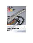
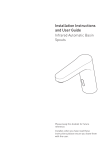
P4 CHAINSTAY INTEGRATED ROCKER
BRAKE (CSIRB) INSTALLATION
TOOLS REQUIRED
•
2, 2.5, 3, 5 mm allen keys
•
8, 9 mm open faced cone wrench
•
Pliers
•
Cable cutters
•
Torque wrench
MATERIALS REQUIRED:
•
1 x P4 chainstay integrated rocker brake
•
1 x Carbon brake stiffener
•
1 x 5 mm allen key bolts
•
1 x preset length of flexi cable housing
•
1 x inline barrel adjuster
•
1 x brake cable
PROCESS:
1. Using the drop out barrel adjusters, first adjust the rear tire’s distance to the cut out and center it in between the chain stays (Note:
clinchers will have a larger wheel radius on average than tubular wheel. This distance also changes as the width of the tire changes.)
If the wheel is not positioned correctly the pads will not contact the braking surface of the rim optimally. (Figure 1)
2. Once the drop out barrel adjusters have been set, remove the wheel to make the rear brake installation easier.
3. Install rocker pivot post using a deep 9 mm cone wrench and torque to 3 Nm. (Note: lube is not needed as the bolts are already
coated with thread prep.) (Figure 2)
4. Place the rocker assembly on the rocker pivot post and torque the bolt to 3 Nm of torque with a 2.5 mm allen key (Figure 3)
5. Install the pivot bolt and non-drive side brake arm with a 5 mm allen key, ensuring that the spring is seated on the vertical landings
on the frame. When the pivot bolt is tight (3 Nm) , the lower washer should spin freely. If it does not spin freely, loosen the pivot bolt
and reposition the lower washer before retightening the pivot bolt. (Figure 4)
6. Repeat step 5 with the drive side brake arm. (Figure 5)
7. Insert slave link sleeve into the slave link (Figure 6), rotate non drive side brake arm into the rocker assembly. Install screw through the
rocker and sleeve. Torque to 1 Nm with and 2.5 mm allen key. (Figure 7)
8. Rotate brake arms and rockers; they should move freely through their ranges without noticeable binding.
9. With the drive side crank arm removed, insert the rear wheel and set brake pads against the braking surfaces on the wheel. Torque
the brake pad bolts to 5 Nm with a 5 mm allen key. (Figure 8)
10. Install the upper portion of the P4 cable system as outlined in P4 cabling service manual.
11. Install the inline barrel cable adjuster onto the rear brake line. The location of this barrel adjuster should be approximately 3 to 4
inches from the top tube entry hole.
12. Set inline cable adjuster to roughly the middle of its travel.
13. Run the rear brake cable until it exits the frame at the bottom bracket area.
14. Install the flexi brake housing over the rear brake cable where it exits the frame and seat it in the rear brake cable BB cable stop. (Note:
the flexi brake housing is a preset length. Using other housing or lengths that are longer or shorter will compromise brake function.)
15. Thread the rear brake cable through the plastic cable housing seat on the rocker assembly.
16. Continue to thread the cable between the two washers and through the cable clamp bolt on the drive side brake arm.
17. Set the quick release on the non-drive side brake arm to the closed position.
18. Compress the brake pads against the wheel with your fingers and pull the rear brake cable tight with a pair of pliers, removing any slack.
19. Clamp the cable tight with a 5 mm allen key. (Figure 9)
20. Secure the lower part of the cable fixing bolt with an 8 mm open faced wrench and continue to tighten the cable fixing bolt to 6 Nm
of torque using a 5 mm allen key,. (Figure 10)
21. Cut cable to desired length and install cable crimp.
P4 DI2 INSTALLATION TIPS - BATTERY
HIDDEN INSIDE WATER BOTTLE
TOOLS
•
6,7 mm drill bit
•
Variable speed power drill
•
Hook tool (a spoke with a 180o bent end)
•
Masking tape
•
X-acto knife
•
Electrical tape
PARTS
•
1 x 10 mm, M5 bolt
•
1 x M5 nylon lock nut
•
Shimano EW 7972 wiring unit
•
Shimano battery Base A plate(Y-7DF 98020)
PROCEDURE
Note: this option renders the water bottle unusable and is not UCI legal.
1. The assembly of the rear brake of the P4 must be completed before the start of this procedure. The bottom bracket cups should be installed
but the crank should not.
2. Wrap masking tape around the 1/4 drill bit with the tape 10 mm from the tip of the bit. Wrap the tape around the drill bit until there is a 3 mm
build up of tape. This will act as a stopper for the bit so that it only drills 10 mm before the tape bottoms out on the frame.
NOTE: If you do not create this stopper, the weight of the drill will potentially cause the drill to hit the opposite side of the frame and compromise
the tube. Any failures in this area will not be covered by warranty.
3. In the centerline of the top tube, drill a 7 mm hole, just behind the headset upper bearing cover on a 2011 P4 (Fig.1), or through the left shifter
cable entry hole on a 2009-2010 P4.
4. Insert the front junction wire into the newly drilled top tube hole, and snake the wire to the bottom bracket exit hole.
5. Insert the hooked tool into the bottom bracket shifter cable exit hole and grasp the wire. Pull the wire out of the bottom bracket cable exit hole.
6. Drill a 6 mm hole into the brake stiffener in position A, and one 7 mm hole in position D (Fig 2).
7. Bolt the bottom bracket junction box through the hole in position A and attach with an M5 nylon lock nut. Position the junction box on an angle
similar to Fig 3.
Note: Excess cable length can be wound back and forth under the bottom bracket junction box before it is affixed to the brake stiffener.
Note: The junction box may sit better against the brake stiffener if the tip is removed.
8. Route the front junction wire from the junction box through the D hole; plug it into the junction wire that was routed through the down tube.
9. Install the brake stiffener onto the frame.
10.Install the rear derailleur onto the rear derailleur hanger and insert the rear derailleur junction wire into the derailleur.
11.Using the adhesive wire covering provided by Shimano, attach the rear derailleur junction wire to the lower surface of the drive-side chain stay.
Cut the adhesive covering so that it ends at the brake stiffener (Fig 4).
12.Install the front derailleur onto the front derailleur hanger and insert the front derailleur junction wire into the front derailleur.
13.Using the adhesive cable covering, fasten the front derailleur junction wire to the lateral side of the drive-side chain stay, similar to Fig 5. An
additional adhesive piece can be used to attach the front derailleur wire to the seat tube, if length permits.
14.Replace the battery B base plate with the A base plate, which is designed for down tube battery placement.
15.Cut the front portion of the B base plate similar to Fig 6; install on top of the water bottle cage using the water bottle bolts.
16.With the X-acto knife, cut the bottom out of the P4 water bottle, similar to Fig 7.
17.Cut a slot in the drive-side of the water bottle to allow the battery wire to exit the water bottle.
18.Using the adhesive cable covering, fasten the battery wire to lateral side of the seat tube, similar to Fig 5.
Note: Excess wiring can be gathered up inside the water bottle.
19.To offer maximum water bottle security, electrical tape can be used to secure the water bottle in the water bottle cage.
Figure 1
Figure 2
Figure 3
Figure 5
Figure 4
Figure 6
Figure 7
P4 Evo CHAINSTAY INTEGRATED
ROCKER BRAKE (CSIRB) INSTALLATION
TOOLS REQUIRED
• 2, 2.5, 3, 5 mm hex keys
• 8 mm open end wrench
• 9 mm deep hex socket
• Pliers or cable pulling device
• Cable cutters
• Torque wrench
• Small flathead screwdriver
MATERIALS INCLUDED
• 1 x P4 Evo chainstay integrated rocker brake consisting of:
• 1 x Non-drive side arm assembly (with quick release attached)
• 1 x Drive side arm assembly (with link attached)
• 1 x pre-cut 130 mm length of flexi cable housing
• 2 x Brake pads (marked L and R)
• 1 x Rocker pivot post
• 1 x M4X12 mm slave link mounting screw (2.5 mm hex drive)
• 1 x Slave link sleeve
• 1 x M3X8 mm rocker mounting screw (3 mm hex drive)
• 1 x Carbon brake stiffener
• 1 x Jagwire Rocket barrel adjuster
• 1 x Brake cable
• 1 x Brake cable end crimp
• Rear race wheel
• Rear training wheel
IDENTIFICATION
P4 brakes can be identified by the serial number located on the non-drive side arm. All P4 Evo brakes have a serial number of CS611XXXX or higher.
PREPARATION
1. Remove all brake parts from their individual packages.
2. Remove the M5 button head cap screws from the pivot posts in both brake arm assemblies (larger ends) using an M3 hex key; set aside. These are
used for mounting the structural cover later in the assembly.
3. Remove the tape from the threaded end of the pivot posts on both brake arm assemblies.
4. Install the left brake pad holder (marked L) on the non-drive side brake arm. The large spherical washer must be next to the pad holder on the inside
of the brake arm. The small flat washer and hex cap must be on the outside of the arm. Tighten the hex cap enough to hold the pad in place. (Figure 1)
5. Repeat step 4 with the drive side (R) brake pad holder on the drive side arm.
PROCESS
1. Ensure both wheels are true and properly dished.
2. Of the two wheels, select the wheel that has the largest diameter to the edge of the tire.
3. Using the drop out screws, adjust the distance of the rear tire to the seat tube. The optimal position will centre the wheel between the chain stays and have
the tire as close to the seat tube as possible without touching. Once the position of the drop out screws has been set, remove the wheel for brake installation.
4. Remove crank arms from the bike.
5. Using a deep 9 mm hex socket, install rocker pivot post; torque to 3 Nm. (Figure 2)
Note: Lube is not needed as the bolts are already coated with thread prep.
6. Place the rocker assembly on the rocker pivot post. Add the rocker mounting screw and torque to 3 Nm with a 2.5 mm hex key. The rocker should be
aligned with the point of the triangle facing the rear and the cable stop facing the non-drive side. (Figure 2)
Note: Do not lube the rocker pivot post. Lube will attract dirt and increase friction. The plastic bushings on the rocker assembly are self lubricating.
7. With a 5 mm hex key, install the pivot bolt and drive side brake arm. Ensure that the spring is seated on the vertical landings of the chain stay and that the
lower pivot washer fits around the bottom of the pivot post. The natural tendency will be for the washer to get pinched off center. Using a flathead
screwdriver, push the washer until it is no longer pinched. When this is done, torque the pivot bolt to 3 Nm. The lower washer should spin freely. If it does
not spin freely, loosen the pivot bolt and reposition the lower washer before retightening the pivot bolt. Repeat with the other brake arm. (Figure 3)
8. Insert the slave link sleeve into the slave link. (Figure 4)
9. Install the slave link screw through the rocker and sleeve. Torque to 1 Nm with a 2.5 mm hex key. (Figure 5)
10.Install each rear wheel and adjust the brake pads to the braking surfaces on each wheel. Torque the brake pad nuts to 5 Nm with a 5 mm hex key.
11.Reinstall the wheel that has the widest rim at the braking surface.
12.Install the Jagwire Rocket cable adjuster into the rearmost ICS-3 top tube entry hole. Install the rear brake cable in the frame through the cable
adjuster and out the hole at the bottom bracket.
13.Install the flexi brake housing over the rear brake cable where it exits the frame; position it in the rear brake cable BB cable stop.
14.Thread the rear brake cable through the plastic cable housing seat on the rocker assembly(between the flat washer and the cable clamp on the non
drive side brake arm).
15.Set the quick release on the non-drive side brake arm to the closed position. The closed position of the quick release is with the arrow pointing
towards the front of the bike.
16.Press the brake pads against the wheel and pull the rear brake cable tight with a pair of pliers or a cable pulling tool.
17.Tighten the cable fixing bolt to 6 Nm of torque using the 5 mm hex key.
18.Cut the cable and install cable crimp. Tuck the excess cable around the brake post.
19.Squeeze the brake to take up the slack in the brake line. Tighten the Jagwire Rocket barrel adjuster to the desired brake lever travel.
20.Balance the spring tension on the drive side and non-drive side brake arms with a 2 mm hex key to ensure that the brake arms are centered over the
rim. Squeeze the brake lever a few times between each adjustment.
21.Insert the front tab of the carbon brake stiffener into the hole at the down tube.
22.Fit the brake stiffener cover over the brake arms; squeeze the brake arms together if necessary.
23.Install the two M5 button head bolts (removed from the pivot posts in the preparation phase) with a 3 mm hex key and torque to 3 Nm.
24.Close the quick release and squeeze brake lever a few times; inspect the installation to ensure that the brake stiffener cover does not interfere with
the brake operation.
25.Install the cranks as usual; ensure the brake cable does not contact the chain ring nuts.
MOUNTING SCREW
STIFFENER
DRIVE SIDE ARM ASSY
SLAVE LINK
NON-DRIVE SIDE ARM ASSY
SLAVE LINK SLEEVE
ROCKER
ROCKER PIVOT POST
CABLE CLAMP
REAR BRAKE CABLE STOP
FLEXI CABLE HOUSING
QUICK RELEASE KNOB
Brake Parts
Spherical side
of washer
towards pad
1 Nm
Toward Non-Drive
Side
3 Nm
Drive side arm shown,
other side similar
Figure 1
Figure 2
3 Nm
Insert sleeve
into link end
Figure 3
Figure 4
1 Nm
Figure 5
P4 DI2 INSTALLATION TIPS - BATTERY
MOUNTED UNDER BOTTOM BRACKET
TOOLS
•
5,6,7 mm drill bit
•
Variable speed power drill
•
Hook tool (a spoke with a 180o bent end)
•
X-acto knife
•
Masking tape
PARTS
•
1 x 10 mm, M5 bolt
•
1 x M5 nylon lock nut
•
2 x M4 nylon lock nuts
•
Shimano EW 7972 wiring unit
PROCEDURE
1. The assembly of the rear brake of the P4 must be completed before the start of this procedure. The bottom bracket cups should be installed
but the crank should not.
2. Wrap masking tape around the 1/4 drill bit with the tape 10 mm from the tip of the bit. Wrap the tape around the drill bit until there is a 3 mm
build up of tape. This will act as a stopper for the bit so that it only drills 10 mm before the tape bottoms out on the frame.
NOTE: If you do not create this stopper, the weight of the drill will potentially cause the drill to hit the opposite side of the frame and compromise
the tube. Any failures in this area will not be covered by warranty.
3. In the centerline of the top tube, drill a 7 mm hole, just behind the headset upper bearing cover on a 2011 P4 (Fig.1), or through the left shifter
cable entry hole on a 2009-2010 P4.
4. Insert the front junction wire into the newly drilled top tube hole, and snake the wire to the bottom bracket exit hole.
5. Insert the hooked tool into the bottom bracket shifter cable exit hole and grasp the wire. Pull the wire out of the bottom bracket cable exit hole.
6. Drill a 6 mm hole into the brake stiffener in position A, two 5 mm holes in positions B and C, and one 7 mm hole in position D (Fig.2).
7. Bolt the bottom bracket junction box through the hole in position A and attach with an M5 nylon lock nut. Position the junction box on an angle
similar to Fig.3.
Note: Excess wire length can be wound back and forth under the bottom bracket junction box before it is attached to the brake stiffener.
Note: The junction box may sit better against the brake stiffener if the tip of the junction box is removed.
8. Bolt the brake plate through the holes in positions B and C, and secure it with the M4 nylon lock nuts.
Note: The battery mounting bolts should be positioned so that they do not contact, or interfere, with the rear brake cable and boss.
9. Route the front junction wire from the junction box through the D hole; plug it into the junction cable that was routed through the down tube.
10.Install the brake stiffener on the frame.
11.Install the rear derailleur on the rear derailleur hanger; insert the rear derailleur junction wire into the derailleur.
12.Using the adhesive wire covering provided by Shimano, fasten the rear derailleur junction wire to the lower surface of the drive-side chain stay.
Cut the adhesive covering so that it ends at the brake stiffener (Fig 4).
13.Install the front derailleur onto the front derailleur hanger and insert the front derailleur junction wire into the front derailleur.
14.Using the adhesive cable covering, affix the front derailleur junction wire to lateral surface of the drive side chain stay similar to Fig 5. An
additional adhesive piece can be used to secure the front derailleur wire to the seat tube, if length permits.
Figure 1
Figure 2
Figure 3
Figure 5
Figure 4
P4 , S2 AND S3 FRONT
CABLE ASSEMBLY
MATERIALS REQUIRED:
•
2 x 24 inch length of 4-5 mm shift cable housing
•
1 x 15 inch length of 5 mm brake cable housing
•
2 x shift cable housing end ferules
•
1 x brake cable housing end ferules
•
Drive side and non-drive side halves of the Cervelo ICS-2 with M4 fixing bolt
•
2.5 mm allen key and torque wrench
•
1 x hook tool, fashioned from a conventional J bend spoke
PROCESS:
1. Bend a spoke in the shape pictured in Figure 1 to fashion the hook tool.
2. Take the piece of brake cable housing and curve the last 3 inches slightly. Insert this cable housing into the rear most hole at the front
of the top tube so it curves towards the front of the bike. (Note: for theS2/S3 please ignore this step) (Figure 2)
3. Insert about 3 inches into the top tube and twist the cable housing 180 degrees so the housing is now curving towards the rear of the bike.
4. Push the cable housing into the down tube until it passed the holes on the side of the down tube.
5. Insert the hook tool into the drive side ICS hole at the top of the down tube. Catch the cable housing with the hook tool and pull
the cable housing out of the top tube until the end is in line with the ICS hole. Pull the cable out of the ICS hole with the hook tool
while pushing more cable housing into the top tube. Stop when you have 2-3 inches of cable housing exposed on the drive side. (Figure 3)
6. Take the first piece of the shift cable housing and curve the last 3 inches slightly. Insert this cable housing into the front drive side hole
at the front of the top tube so it curves towards the front of the bike. (Figure 4)
7. Repeat steps 3-5. (Figure 5)
8. Take the second piece of the shift cable housing repeat steps and curve the last 3 inches slightly. Insert this cable housing into the
front non-drive side hole at the front of the top tube so it curves towards the front of the bike.
9. Repeat steps 3-5. (Figure 6)
10. Place the shifting and brake cable ferrules onto their appropriate cable end.
11. Place the non drive side ICS-2 onto the shift cable housing that exits the non drive side of down tube. Push the extra cable housing
up into the frame and insert the ICS into the frame.
12. Place the drive side ICS-2 onto the brake and shifting cable housings that exits the drive side of down tube making sure that the
brake housing is inserted into the upper boss and the shift housing is inserted into the lower boss (Note: for the S2/S3 frame will only
use the shift cable and not the rear brake cable). Push the extra cable housing up into the frame and insert the ICS-2 into the frame. (Figure 7)
13. Insert the 2.5 mm allen key into the bolt hole of the drive side ICS-2 to ensure both halves of the ICS-2 are aligned.
14. Grease threads of the M4 fixing bolt, insert into drive side ICS-2 and torque to 1.5 Nm. (Figure 8)
15. Cut the free ends of the shifting and brake cables to their appropriate length to allow the handlebars to turn without binding. (Note:
For the P4 the rear brake cable will need an inline barrel adjuster for proper set up of the rear brake) (Figure 9)
16. Proceed to run the shifting and rear cables just as you would on any aero Cervelo frame.
Hook tool
Brake housing
Non-drive side ICS-2
Cable ends
Drive side ICS-2
2.5mm
M4 ICS-2 fixing bolt
Shifter housing
Figure 1
Figure 2
Inline barrel adjuster
Figure 3
Figure 4
Figure 5
Figure 6
Figure 7
1.5Nm
Figure 8
Figure 9
22. Loop cable over the hook and under the spring on drive side brake arm so it does not come into contact with the crank’s chain ring bolts. (Figure 11)
23. Adjust (shorten) the inline cable adjuster as required to move the pads away from the rim and give the desired engagement point on
the brake lever travel.
24. Balance the spring tensions on the drive side and non-drive side brake arms with the 2 mm grub screws to ensure that the brake arms are centered
over the rim. Squeeze the brake lever a few times between each adjustment. Spring tension will be higher on the non-drive side brake arm. (Figure 12)
25. To install brake stiffener rotate quick release so that it is perpendicular to the wheel. Insert the BB tab of the brake stiffener into the
hole at the front of the cable trench.
26. Fit the stiffener over the brake arms, squeezing the brake arms together to fit the quick release through the slot in the stiffener. (Figure 13)
27. Install the two M5 button head screws with a 3 mm allen key and torque to 3 Nm. (Figure 13)
28. Close the quick release and squeeze brake lever a few times and inspect the installation to ensure that the stiffener does not
interfere with the brake operation.
29. Install crank arm ensuring that the rear brake cable does not make contact with the chain ring bolts.
3Nm
Figure 1
Figure 2
3Nm
3Nm
Figure 3
Figure 4
3Nm
Figure 5
Figure 6
5Nm
1Nm
Figure 7
Figure 8
6Nm
Figure 9
Figure 10
Figure 11
Figure 12
Figure 13