1
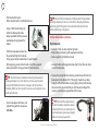
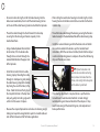
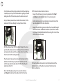
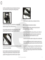
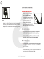
S5 Supplementary Manual Cervélo S5 Supplementary Manual 1 Cervélo S5 Supplementary Manual INTRODUCTION: Welcome to the Cervélo family and congratulations on purchasing the S5. The S5 is the most advanced aerodynamic road bicycle ever developed by Cervélo. Inspired by the demands of the world’s top pro riders, the S5 deploys everything Cervélo has learned in 16 years about aero design; look closely and you’ll see many elements of our industry benchmark P-series bikes. Those aero technologies are combined with material engineering honed in our Project California facility to produce bikes that are super-responsive and agile, yet smooth and comfortable on the toughest road surfaces. The main distinguishing features of your S5 are as follows: • Dropped Downtube • Extended Cut-Out • Built for Bottles • Shielding Stays • BBright We hope you enjoy the S5 as much as we do. Enjoy the ride and thanks for choosing Cervélo. NOTE: This manual is designed as a supplement to your Cervélo Owner’s Manual, and is specific to the unique features of the S5. It contains important installation and set-up information; we strongly encourage you to familiarize yourself with the contents and the new technologies before you begin assembly or adjustment of your bike. Should you decide to part ways with your Cervélo S5 in the future, please remember to pass this manual along. Please refer to your Cervélo Owner’s Manual for general safety, setup, and maintenance information for your S5 bicycle. Note that Cervélo strongly recommends the use of a torque wrench for tightening all bolts referenced in this manual. For further information on the S5 or your Cervélo family please visit www.cervelo.com. Cervélo S5 Supplementary Manual CONTENTS 1. Features Diagram. . . . . . . . . . . . . . . . . . . . . . . . . . . . . . . . . . . . . . . . . . . . 1 2. Assembly Instructions . . . . . . . . . . . . . . . . . . . . . . . . . . . . . . . . . . . . . . . 6 A. Fork Installation . . . . . . . . . . . . . . . . . . . . . . . . . . . . . . . . . . . . . . . . . . . . . . 6 B. Seatpost Installation. . . . . . . . . . . . . . . . . . . . . . . . . . . . . . . . . . . . . . . . . 10 C. Rear Brake Caliper Installation. . . . . . . . . . . . . . . . . . . . . . . . . . . . . . . . 12 D. Rear Brake Cable Installation. . . . . . . . . . . . . . . . . . . . . . . . . . . . . . . . . 13 E. Routing Derailleur Controls . . . . . . . . . . . . . . . . . . . . . . . . . . . . . . . . . . 15 3. Fine–Tuning Instructions. . . . . . . . . . . . . . . . . . . . . . . . . . . . . . . . . . . . 19 A. Installing Water Bottle Cages. . . . . . . . . . . . . . . . . . . . . . . . . . . . . . . . . 19 4. Maintenance and Replacement Instructions. . . . . . . . . . . . . . . . . . 20 A. Replaceable Derailleur Mounts. . . . . . . . . . . . . . . . . . . . . . . . . . . . . . . 20 Cervélo S5 Supplementary Manual 1. FEATURES DIAGRAM A Map To Your Cervélo S5 Drainage hole Single bend cable guide Front Derailleur cable hole Di2 battery cable hole Rear Derailleur cable hole Di2 Shift control cable hole Cervélo S5 Supplementary Manual Di2 battery holder mount 5 2. Assembly instructions A. Fork Installation Your Cervélo S5 uses a fork which has been engineered specifically to fit this bike and maximize performance. Please familiarize yourself with the complete Cervélo Fork Owner’s Manual supplied with the bike before proceeding with any installation or service. Parts Required: • Cervélo Fork Owner’s Manual • 75mm fork insert & star nut • Sandpaper (120-180 Grit) • Epoxy packet (Hardman, Fast Setting Red Package #04001) • Isopropyl Alcohol wipe • Wooden mixing stick • Stem top cap • M6 stem top cap bolt STEP 1: Measuring and Cutting NOTE: This procedure assumes that the frame was adequately prepared to accept the bearings (i.e. head tube was faced and reamed if necessary to ensure the faces are square and inner dimensions correct). • If not pre-installed, press the crown race onto the fork crown race seat using an appropriate installation tool. (Park Tool CRS-1 Crown Race Setting System or equivalent). • Test fit the fork into the head-tube with all headset components, the required number of spacers, and the stem desired by the customer (following all manufacturers’ instructions). • Covering the inner faces of the frame and the bearings with appropriate grease (Park Tool PolyLube 1000 or equivalent), press the upper & lower headset bearings into the head tube. Cervélo S5 Supplementary Manual WARNING: In addition to the upper bearing ‘volcano cone’ cover which can measure up to 15mm tall, a maximum of 35mm of spacers can be safely used below the stem with any Cervélo fork. Do not exceed this maximum spacer height of 50mm overall. 6 • Apply the minimum pressure needed to ensure the complete assembly is fully seated. • Tighten the stem’s steerer tube clamp bolts just enough to hold the desired position, and using a light coloured grease pencil, mark the steerer tube at the top of the stem. Tip: Start cutting with the saw blade held in a horizontal position and continue cutting until the blade nears the bottom of the tube. Loosen the vice and rotate the steerer 90 degrees. Resume cutting the final, vertical section with great care, supporting the free end to ensure that no splintering of the steerer tube occurs. • Disassemble all parts and clearly draw a line on the steerer tube 4mm below the first mark made. STEP 2: Bonding Tip: Remember, cutting the steerer tube too long will result in a loose headset, while cutting the steerer tube too short renders the fork unusable. Tip: Wrap the steerer tube with masking tape immediately below the lower, final cut mark. This will reduce the likelihood of splintering during the cutting process. • Cervélo recommends using a carbon specific blade (or a fine tooth blade with greater than 32 teeth per inch). • To ensure the accuracy of your cut, please utilize a cutting guide made for fork steerer tubes. Cervélo highly advises against clamping the steerer tube directly into the vice, as this could result in cracking and damage from over-tightening. Wearing gloves and safety glasses, use silicon carbide (SiC) 120-180 grit sandpaper to carefully sand the cut end to remove any sharp edges or splinters. NOTE: Do not remove material from the outer steerer tube wall. Tip: Always sand along with the grain of the material — not across or opposite the grain — which can lead to splintering. • Carefully sand the inside of the steerer tube from the cut end down 75mm to prepare the surface for bonding. • Tap the fork over a disposal bin to remove all excess carbon dust. • Using an isopropyl alcohol wipe, thoroughly clean the sanded area inside the fork steerer tube to remove all carbon dust. Allow 30 seconds for the alcohol to dry before proceeding. Cervélo S5 Supplementary Manual 7 • Remove the insert from the plastic packaging, taking care to only touch the ends of the insert. Test fit the insert into the steerer tube without glue to ensure it will fully seat in the steerer tube. Tip: If the insert will not fit completely into the steerer tube, measure to see how far it sticks out above the steerer tube. Remove the insert and mark that same distance as measured up from the bottom of the insert (tapered end). Carefully cut off the insert end using a hacksaw, and file the cut end to remove any sharp edges. Note that the insert must be cut from the bottom only. Test fit the insert again to ensure it will fully seat in the steerer tube. Tip: To ensure the top of the insert fits flush with the top of the steerer tube, lightly bevel the inside circumference of the steerer tube (sanding along the grain of the carbon) to remove the minimum amount of material to allow the insert to sit flush. • Ensure all bonding surfaces are cleaned of all debris and finger oils. Use isopropyl alcohol to clean the inside of the steerer tube and the outside of the insert as necessary. Please ensure that the cleaning of both parts is completed no less than 5 minutes before applying the epoxy. Once cleaned, the bonding surfaces must not be touched before the epoxy is applied. • Using gloves, the wooden mixing stick, and a clean disposable surface; fully mix the epoxy in the kit supplied with the fork according to the package instructions. Apply a layer to the outer surface of the insert. Concentrate the epoxy towards the bottom (tapered) end of the insert. Excess epoxy may be added to the inside of the steerer tube. • Carefully slide the insert into the steerer tube while rotating it slowly until the flared end sits flush with the top of the steerer tube. The rotation will help spread the glue over the bonding area. • Wipe away any excess glue from the outside surface of the steerer tube with an isopropyl alcohol wipe. • Once complete, re-check that the insert is sitting flush in the steerer tube. • Set the fork aside and allow it to sit undisturbed for the full curing time as noted on the epoxy packet. Do not attempt to fit the fork into a bike prior to the completion of the full curing cycle. WARNING: Moving the insert before the epoxy has fully cured will damage the bond, and will greatly reduce the strength of the fork, potentially resulting in a failure. Do not touch the fork while the epoxy is curing. STEP 3: Assembly • Check the stem, spacers and headset components to make sure there are no sharp or rough edges which could cut or damage the steerer tube. If any rough edges are detected, have the components repaired (sharp edges removed) or replaced before proceeding. Cervélo S5 Supplementary Manual 8 • Press the upper and lower headset bearings into the frame, and insert the fork into the head tube. • Lightly grease the threads of the stem top cap bolt, and the stem clamp bolts. • Slide the compression ring onto the steerer tube, and down until it fully seats in the top of the upper headset bearing. • Place the stem cap on top of the stem and insert the greased bolt through the cap to engage with the star nut. Tighten the bolt only enough to remove all play from the headset, and ensure that the fork still rotates freely. Usually this equates to 1 to 2Nm of torque. Tip: The split in the compression ring must be oriented toward to left or right side of the steerer tube — never towards the front or back. • Assemble the head-set as per manufacturer’s instructions. • Slide the spacers and stem onto the steerer tube. Do not use grease on the fork steerer tube. The use of Tacx Carbon Assembly Compound™ or equivalent friction paste is recommended to help secure the stem. • Confirm that the distance between the top of the stem and the top of the alloy insert is between 2 and 4mm. If not, add or remove spacers to achieve this distance. • Visually check the alignment of the stem with the front wheel and make any necessary adjustments. WARNING: To avoid damaging the fork, never try to align the stem without first fully loosening the stem's steerer clamp bolts. • Tighten the stem bolt(s) to the steerer tube to a maximum of 5Nm using a torque wrench (Note that this torque rating applies to the supplied 3T stem – follow manufacturer’s instructions if other stem is used). When tightening, alternate between bolts after each full turn to ensure that torque is applied evenly to the fork steerer tube. Cervélo S5 Supplementary Manual 9 B. Seatpost Installation In order to provide maximum adjustability while maintaining optimal aerodynamic properties, the S5 utilizes an internal wedge system to secure the seatpost. Although the system is easily removable, it is important to follow these steps to ensure simplicity of installation. • Reinstall the outer rail cradles by replacing the 5mm through/ fixing bolts to hold the saddle cradles and rails in position. • Establish your saddle tilt. If fixing bolt is too tight, the saddle will be difficult to move and will require disassembly and reassembly to loosen the system. Parts Required: • Cervélo S5 seatpost • Saddle • S5 seatpost wedge clamp • To install your saddle on the seatpost, use two 5mm allen keys to loosen the saddle fixing bolts and remove them completely. • Remove the outer rail cradles leaving the inner cradles in place. Locate the saddle rails in these cradles. These should be facing ’up’. Outer Cradle Inner Cradle Tip: Note that non-drive side internal rail cradle mechanism is tapered and serrated to match the non-drive side port in the seatpost. These cannot be reversed without damage occurring. • Once the saddle is in the desired location, torque the fixing/ through bolt to 12Nm. Please note that two allen keys must be used simultaneously to prevent the bolt from turning during torque application in order to properly clamp the saddle. Tip: If required, to determine whether to use front or rear seatpost hole position, please consult the S5 geometry chart at www.cervelo.com, or speak with your Cervélo dealer who can give you information on the best setup for your needs. Cervélo S5 Supplementary Manual 10 • Ensure that portion of the S5 seatpost to be inserted into the frame is coated with carbon assembly compound, and insert the post into the frame a minimum of 6.5cm up to a maximum of 10cm. If your post is uncut (as delivered) there is a minimum insertion line on the post to indicate 6.5cm insertion. Tip: If you cannot lower your seatpost sufficiently to get the proper position, you can either cut your post or purchase a shorter length post from your Cervélo dealer. If using a cut seatpost, the minimum insertion mark may no longer be correct or present. In this case, ensure your post is inserted at least 6.5 cm into the frame to avoid damage. See below for cutting instructions. Tip: If over time the seatpost wedge bolt begins to feel gritty or rough, simply remove com pression/ expander bolt from the wedge, clean it and apply grease to the threads. Reinstall. • Slide the seatpost wedge clamp into frame in front of the seatpost until the top of the unit is flush with the top tube profile. • Once the correct height has been chosen, tighten the compression screw to a maximum of 8Nm. Tip: Apply a thin coat of carbon assembly compound to the outer, forward facing curved surface of the seatpost wedge to limit possible long term adhesion and/or creaking. Be careful not to get grease onto the rearward compression face through, as this could promote seatpost slip. • To set the seat position lower, loosen the wedge bolt and then use gentle taps on the saddle top to slowly change the height. If the saddle needs to be raised, holding the frame at the seat tube/top tube junction with one hand, use a slight upward rocking motion to walk the seatpost higher with the other. Tip: Be gentle! You may need to hold the seat clamp wedge in place with one hand while the post is being pulled up. When removing the seatpost entirely, take care to ensure that the seatpost clamp does not fall into the frame. If it does, you may need to turn the entire bike upside down to get it out. Cutting Your S5 Seatpost IF your seatpost requires cutting for proper fit, Cervélo recommends the use of the Park Tool Oversized Saw Guide SG 7.2 to ensure an accurate cut. Please refer to Park Tool’s user manual for diagrams and descriptions of the recommended tool set-up. Cervélo S5 Supplementary Manual 11 • Taking care to maintain the minimum required seatpost insertion of 6.5cm and maximum of 10cm, carefully measure and use a light coloured grease pencil to accurately mark the cut-off location on the seatpost. • Insert the S5 seatpost in the Park Tool SG-7.2 Saw Guide (or equivalent) so that the cut-off line can be seen clearly through the blade guide in the tool. Clamp the guide into a vice to hold the seatpost steady while cutting. • Using a blade designed specifically for cutting carbon composite materials (or a fine tooth blade with greater than 32 teeth per inch); proceed with cutting the seatpost (as per Park Tool’s instructions). Tip: Wrap the seatpost with masking tape immediately above the final cut mark. This will reduce the likelihood of splintering during the cutting process. • After the cut is complete, use a fine grit sandpaper to carefully remove any fraying or burring from the cut end. • Return the seatpost to the tool, and clamp approximately 10cm from the cut end. • Reposition the tool in the vice so that it holds the seatpost at approximately 45 degrees, with the leading edge down, and the seatpost head located at the higher end. • With a grease pencil, mark a point 1cm from the cut end on the trailing edge of the seatpost. • Placing the blade of your saw on the grease pencil mark, very carefully proceed to cut straight down resulting in a 45 degree chamfer being cut onto the trailing edge of the seatpost. • Carefully sand the end and after applying carbon assembly compound, return to the frame. Tip: This is an advanced step, and should only be attempted by a professional using proper equipment. The second cut is done to promote ease of insertion, and to minimize risk of damage to the seat tube. It does not have any impact on the post-assembly functionality of the S5 seatpost. C. Rear Brake Caliper Installation The installation of the rear brake requires the attachment of the S5 specific brake plate to the caliper before it can be fitted to the frame. Note: If you have purchased your S5 as a complete bicycle, the rear brake caliper will have been pre-installed at the factory. Parts Required: • Cervélo S5 brake plate • Cervélo S5 brake plate fixing nut (see image) Cervélo S5 Supplementary Manual 12 • 10mm brake fixing nut • Brake manufacturer’s installation manual Tip: Ensure that the brake plate is fully located in frame before initiating attachment. There is a risk of cross threading the brake plate fixing bolt if the plate is not seated correctly in the frame before tightening is attempted. • Using a 10mm brake fixing nut, attach the brake plate to the brake’s pivot bolt with the recessed counterbore facing toward the caliper. D. Rear Brake Cable Installation Parts Required: • Cervélo S5 click-in cable stop for top tube • Brake cable and housing with appropriate ferrules • Brake supplier’s installation manual • With the brake plate centred on the pivot bolt, tighten the brake fixing nut per brake manufacturer’s specifications. • After applying grease to the threads, install the supplied brake plate bolt in the upper hole of the brake plate. Tip: For most brake installations including Shimano and Campagnolo brands, a 4mm allen key can be used to attach a standard M5 bolt to the frame. However, for some others, including SRAM, an 8mm wrench must be used to tighten a hex head bolt correctly. • Insert brake plate into frame, and tighten fixing bolt to a maximum of 4.5Nm. • Locate the forward integrated cable stop (ICS) on the non-drive side of the top tube. • Measure the length of cable housing needed to reach from the brake lever to the forward ICS. This length should be set long enough so that the handlebar can (lightly) contact with the top tube when bars are turned fully, and not cause binding of the steering mechanism or application of the brake. Tip: Note that the cable housing for the front brake should be routed behind/within the arc created by the rear brake housing to ensure smooth cable and steering operation. Cervélo S5 Supplementary Manual 13 • Once cut to desired length, install the brake housing into the brake lever counterbore, then install the brake housing ferrule on the end of the cable housing to be inserted into the top tube. • After cutting the outer brake housing to desired length, install a housing ferrule on the forward end to be inserted into the clickin cable stop. • Thread the cable through the fixed forward ICS cable stop ensuring that the housing end locates squarely in the counterbore/hole. • Thread the brake cable through the housing, ensuring that ferrule is located securely in the counterbore/hole of the cable-housing stop. • Using a hooked spoke or other method of extraction, fish the brake cable though frame and exit through the rearward hole found on the upper side of the top tube. • Install the rearward housing end into the brake arm and attach the rear brake cable to the brake as per the manufacturer’s instructions. With the rear wheel installed, check that the caliper is centred and braking power is adequate. Ensure that all housing stops and ferrules are secure. Tip: If your brake does not provide an accessible centering tool, remove the brake from the frame, and realign the brake plate on the brake’s pivot bolt. • Install the Cervélo S5 click-in-cable housing stop by threading the cable through its small opening, and placing the cable-housing stop (with retention clip facing the rear of the bike) in the frame. Hook the forward facing lip of the stop into the hole in the top tube and push gently on trailing edge until a click is felt to secure it in place. • Measure the required top tube to rear brake arm housing length, taking care to permit enough bend to permit a smooth cable arc and sufficient movement for full brake application. • If a centering adjustment is required, do so as per the brake manufacturer’s recommended method. Cervélo strongly recommends against manual rotation of the caliper as it may result in loosening of the brake fixing nut, and compromised brake performance. Cervélo S5 Supplementary Manual 14 E. Routing Derailleur Controls STEP 1: Front Derailleur Cable Installation Understanding that a bicycle needs to be something other than a frame with components hung on it, Cervélo began to design the S5 taking into account the requirements of both rider and equipment. Designed to handle both traditional mechanical style gear controls as well as electronic shifting cables, the S5 provides seamless integration of all shifting systems regardless of method or brand. Please note that Step 1 assumes that the fork, headset, front brake, front wheel, handlebar, and brake/shift levers have been installed and positioned according to the customer’s personal fit requirements (and manufacturer’s instructions). Your S5 utilizes Cervélo’s ICS3 (Integrated Cable Stop) system to make the cable installation a simple task, and to overcome the high cable friction problems traditionally associated with internally routed cables. A key component of this system is the S5’s singlebend cable guide (see www.cervelo.com for more information). If you choose to use an electronic shifting system, the S5 has been designed to accommodate the most efficient internal routing methods without sacrificing frame integrity, or aerodynamics. Tip: When tightening the stem faceplate bolts to secure the handlebar to the stem, tighten evenly in a star pattern as shown. When finished, the gap between the stem body and faceplate should be equal top & bottom and side–to–side. Parts Required: • • • • • • Cervélo S5 click-in cable housing stop for chainstay Cervélo S5 single-bend cable guide for bottom bracket Manufacturer’s recommended shift housing and cables Manufacturer’s recommended cable housing ferrules 1 in line cable adjuster (optional) Derailleur manufacturer’s installation manual 1 4 3 2 • With the bars and stem installed to the correct height and angle, install an appropriate length of uncut cable housing from the shift lever along the handle bars to allow the housing to exit the tape at the back or bottom of the bar. Cervélo S5 Supplementary Manual 15 Tip: Use electrical tape to secure the housing to the bars and run the cables before installing the bar tape – this allows you to adjust the housing length and position easily. • Measure and trim the housing to allow it to pass by the approximate top of the fork steerer before reaching the first hole in the top tube (behind the head tube – labelled FD for Front Derailleur). The S5 was designed to have the lowest amount of cable friction with this length of housing. • Re-measure and cut the housing length to compensate for the adjuster height. Tip: The in-line cable adjuster supplied with the S5 requires the removal of approximately 25mm of cable housing length as compared with not using the adjuster. • Ensure that the front two cable holes (FD and RD) in the top tube contain a pink-coloured plastic liner prior to cable installation. Tip: For more on cable friction, please consult www.cervelo.com • Install the optional in-line cable adjuster directly into the counterbore of the FD hole and insert cable housing (with ferrule) into the top of the adjuster. • Insert cable into housing and adjuster, and feed into the FD cable hole to approximately 70-80% of its length in order to position the end for bottom bracket (BB) routing. Tip: ICS3 uses pre-lubricated tubes fixed inside the frame into which the cables will route. It will automatically turn the cables in the correct direction to exit at the Bottom Bracket. For more on ICS3, please visit www.cervelo.com Cervélo S5 Supplementary Manual 16 • Turn the frame vertically on the workstand so that the head tube is pointing up. Using a small flat screwdriver, gently pry the BB cable guide from the frame to expose the cable access port. STEP 2: Rear Derailleur Cable Installation • Using a hooked spoke or other method of extraction, fish the cable out of the frame through the large (forward) hole. • Install cable housing ferrule and locate in the centre hole of the top tube (labelled RD for Rear Derailleur). • Repeat the cable housing measuring procedure from Step 1 excluding any considerations for an in-line cable adjuster. • Repeat the cable fishing process to draw the inner cable through the forward hole in the Bottom Bracket shell (so that both cables are through the Bottom Bracket Shell) ensuring that it runs to the DRIVE-SIDE of the FD cable. • With the cable running OVER the carbon bridge in the access port, feed the cable across the middle round hole and into the rear hole and up the rear of the seat tube so that it exits the frame below the FD mounting bracket. • Place the plastic tube over the cable and feed down until the bottom end of the tube just protrudes out of the rear hole, with the top end protruding above the BB and feeding the cable towards the FD. The Rear Derailleur cable remains internally routed beyond the bottom bracket, and therefore must now be fished down the drive-side chainstay. • Draw cable through opening as far as possible and leave until Step 4. Do not attach the cable to the FD at this time. Cervélo S5 Supplementary Manual 17 • Feed the rear derailleur cable across the bridge in the access port, and into the rear opening of the cable guide port. • Do not attach the cable to the rear derailleur at this time. • Feed the cable along the drive-side chainstay until the cable bottoms out against the end of the chainstay. • Using a hooked spoke or other method of extraction, fish the cable through the hole on the upper face of the chainstay. STEP 3: Single–Bend Cable Guide Installation Now the S5 single-bend cable guide must be put in place to ensure smooth and precise shifting. • Lift the shift cables off of the cable port bridge, and slide the S5 plastic cable guide underneath them while ensuring that the deeper cable track is oriented toward the drive-side. • Locate the rear derailleur cable in the deeper drive side cable track. • Locate the front derailleur cable in the remaining track ensuring that the plastic cable guide tube does not cover cable in the track. • Thread the click-in cable stop onto the cable so that the retention clip faces the rear of the bike. • Insert the cable stop into the frame by hooking the forward facing lip of the stop into the hole in the top tube and push gently on trailing edge until a click is felt to secure it in place. • Locate the S5 cable guide nipple over the middle 5mm hole in the cable-port bridge, and push firmly to secure the guide in place. When seated properly, the guide should sit flush with the bottom bracket shell. Cervélo S5 Supplementary Manual 18 3. Fine-Tuning Instructions A. Installing Water Bottle Cages STEP 5 • Measure, cut, and install the chainstay to rear derailleur cable housing and proceed with front and rear derailleur installation and adjustment as per the derailleur manufacturer’s guidelines. • The S5 was designed to offer the best possible aerodynamics on a road bicycle, while remaining customizable to the rider’s specific hydration requirements. As traditional bottle designs are inherently un-aerodynamic, the S5 offers options for customized mounting. Maximized aerodynamics • Tests have proven that the most aerodynamic position for a traditional round feeding bottle is low on the down tube. • Mount your bottle cage to the lower two M5 inserts on the down tube. Tighten the bolts to a maximum of 3Nm. Maximized Fluid Capacity • If you have greater hydration requirements than a single bottle can supply, you will need to use the seat tube location to locate your second bottle. • Attach the first bottle cage to the seat tube mounted M5 inserts and tighten the bolts to a maximum of 3Nm. Cervélo S5 Supplementary Manual 19 • Mount the second bottle cage to the upper two M5 inserts on the down tube tightening each to a maximum of 3Nm. 4. Maintenance and replacement instructions • Remove front derailleur from the mount. • Using a 3mm allen key, remove the two tapered M4 fixing screws from the mount and remove assembly from the seat tube. • Inspect the frame for damage. A. Replaceable Derailleur Mounts • Ensure that the threads of the fixing screws are clean, and install Loctite 242 (blue) threadlock on the bolt threads as per the manufacturer’s instructions. Your S5 utilizes replaceable front and rear derailleur mounts for simplified service and extended frame life. In the unfortunate event that replacement is required, Cervélo recommends authentic S5 replacement parts be used. • Reinstall the front derailleur mount by aligning the bolt holes over the inserts in the seat tube. Loosely install the top fixing screw first, and then lower. Tighten the screws equally to ensure that the mount locates squarely against the frame. Front Derailleur Mount • Tighten the fixing screws to a maximum of 2Nm. Parts Required: Rear Derailleur Mount • Cervélo S5 front derailleur mount • 2x M5 Cervélo front derailleur mount fixing screws • Loctite® Threadlocker Blue 242 (recommended) Parts Required: • Cervélo S5 rear derailleur mount • 2x M3 Cervélo rear derailleur mount fixing screws Cervélo S5 Supplementary Manual 20 • Remove rear derailleur from the mount. • Using a 2mm allen key, remove the two tapered M3 fixing screws from the mount and removed the assembly from the dropout. • Inspect the frame for damage. • Ensure that the threads are clean. • Ensure that the frame where the mount seats is clear on any debris or contamination. • Reinstall the Cervélo rear derailleur mount by loosely installing top fixing screw first, then lower. Tighten the screws equally to ensure that the mount locates squarely against the frame. • Tighten the fixing screws to a maximum of 1Nm. • Reinstall the wheel in the frame, and use a derailleur hanger alignment gauge to check that the Hanger is square relative to the wheel. If you have any questions about your S5 or for further assistance, please contact Cervélo Customer Service or your authorized Cervélo retailer. Cervélo S5 Supplementary Manual 21