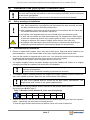
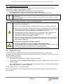
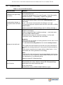
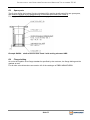
1
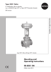
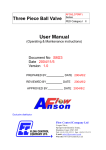
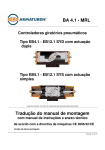
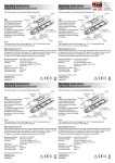
BA 4.9 - DGRL/MRL Impeller valve Series FS-M for pulp (powdery/granular) and paste goods DN150 - DN400 Original – installation instruction with service instruction and technical annex as per as per EC-Pressure Direction 97/23/EG EC Machinery Direction 2006/42/EG English version Revision: 00-09.13 INS TALLATION- AND O P ERATING INS TRUCTION IMP ELLER VALVE S ERIES FS -M Contents Page A) GENERAL 3 A1 A2 A3 A4 SYMBOLS VALVE DESTINATION VALVE MARKING TRANSPORT AND STORAGE 3 3 4 4 B) INSTALLATION IN THE (PIPE) SYSTEM / FUNCTIONAL CHECK 5 B1 B2 B3 B4 B5 5 5 6 7 7 SAFETY WARNINGS AT INSTALLATION PRECONDITIONS FOR INSTALLATION STEPS AT INSTALLATION PRESSURE TEST BEFORE START-UP ADDITIONAL INFORMATION: DISASSEMBLING C) NORMAL SERVICE AND INSPECTION 8 C1 IMPORTANT SAFETY WARNINGS AT SERVICE AND MAINTENANCE C2 AUTOMATIC SERVICE C3 TROUBLESHOOTING 8 8 9 D) TECHNICAL ANNEX / PLANNING DOCUMENTS 10 D1 D2 D3 D4 D5 D6 10 10 10 10 11 11 TECHNICAL SPECIFICATION OF THE VALVE ADMISSIBLE PRESSURE ADMISSIBLE SERVICE TEMPERATURE DRAWING / PART LIST SPARE PARTS FLANGE BOLTING MANUFACTURER’S DECLARATIONS 12 This manual, EBRO-catalogue-sheets and other information – even in other language – may be asked from www.ebro-armaturen.com or from EBRO ARMATUREN GmbH Karlstraße 8 D-58135 Hagen (02331) 904-0 Fax (02331) 904-111 [email protected] Seite 2 INS TALLATION- AND O P ERATING INS TRUCTION IMP ELLER VALVE S ERIES FS -M A) General A1 Symbols Warning notices and tips are marked by symbols: XXXXX Danger / Warning Points out a dangerous situation which may cause personal injuries or death. Advice Has to be respected. Information Information useful to follow. If these notes and warnings are not respected by the user, dangerous situations may occur and may invalidate the warranty of the manufacturer. A2 Valve destination An Impeller Valve FS-M installed in the bottom of a silo in the bulk industry is destined to control or dose pulp (powdery or granular) material or to charge/discharge pulp material to mixing or weighing assemblies in the admissible range of pressure and temperature. At installation in a vertical pipe section the flow may be powered by gravity only. Powdery or granular pulp material should be dry. The impeller Valve FS-M may be as well • installed in a horizontal or inclined pipe section then powdery or granular pulp shall be conveyed pneumatically (or equivalent), • used for liquid or paste product streams or for a suspension of liquids with small solid particulates. Then a pump or worm conveyor is necessary for conveyance. The impeller wheel of the impeller valve shall be driven – continuous or intermittent – by a unit motor/worm gear – the electric control circuit generally is planned and supplied by the customer. As a rule the impeller valve shall be installed between flanges EN1092-1 or EN1759-1, with mating faces form A or form B, installed parallel and in line. Any other kind of installation shall be agreed by EBRO ARMATUREN. The maximum admissible temperature is marked with TS in the valve nameplate, the maximum admissible differential pressure at the impeller wheel is 3 bars up to DN300 and 1 bar for DN>300. Note 1: A load from filling level of 3 kp/cm² (=30 t/m²) corresponds to 3 bars. Note 2: The body of the impeller FS-M may be loaded up to 6 bar and up to 160°C, even higher if agreed by EBRO ARMATUREN up to 250°C. The first start-up of the valve shall not be activated before the following documents have been observed: • <Declaration of conformance to EC-Directives> – see last pages of this instruction, • This <Installation and operation instruction>, added to the valve supply. The use of the valve in an -hazardous area is allowed only, if the customer has specified this risk in his order and only, if EBRO ARMATUREN has marked this valve with the -label. In this case the user shall strictly observe additionally the EBRO-instruction BA 4.9-ATEX If this <Valve destination> specified above is not respected by the user, dangerous situations may occur and may invalidate the warranty of the manufacturer. Seite 3 INS TALLATION- AND O P ERATING INS TRUCTION IMP ELLER VALVE S ERIES FS -M A3 Valve marking Each valve is marked at the body nameplate as follows: for Marking Remark manufacturer valve type EBRO ARMATUREN FS-M Address see page 2 as described in 4.9 of the EBRO catalogue Digits 1-6: EBRO-serial-no, digits 7-9: position in confirmation of order, digits 10-12: current piece of the order confirmation (Body-marking) i.e. DN80 This is the necessary nominal pressure of the flanges number for the upper limit depending of shaft seal material (Body-marking) body material (nameplate marking) impeller wheel material (nameplate marking) shaft material serial-n o i.e. 123456/012/001 *) Nominal Diameter Nominal Pressure max. temperature material DN (and number) i.e. PN 6 TS (and number) i.e. aluminium or 1.4301 i.e. 1.4408 i.e. 1.4104 Note 1: *) the year of manufacture is coded in the serial-no. Note 2: The electric motor has an additional nameplate. Note 3: An impeller valve for –application has an additional nameplate. All markings shall remain legible to identify the valve at any time later. A4 Transport and storage For shipment and storage observe: • Handle the valve with the protective packaging just until the installation into the (pipe) system. • Store it at room temperature and protect the valve from harsh environmental conditions, such as dirt, debris and humidity. • If a hoist shall be used for better handling, fix the lifting devices at the valve body only, not at the actuator unit. See Fig.1 to Fig.3. • Do not fix belts or straps at the wings of impeller valves. Protect specifically the protruding impeller wheel at storage. Put down the valve on the body surface only and support it by a wooden truss. ISO 2230 describes the storage conditions and limited lifetime for elastomeric spare parts (O-ring and shaft seal): Store it in a cool and dark place without UV-light. Fig.1 Fig.2 How to fix lifting belts Seite 4 Fig.3 INS TALLATION- AND O P ERATING INS TRUCTION IMP ELLER VALVE S ERIES FS -M B) Installation in the (pipe) system / Functional check This instruction gives safety warnings for installation of valves in the (pipe) system. The user shall complete this instruction with all necessary information that are necessary for the in-site (pipe)system More safety information may be included in the relevant manual of the actuator. B1 Safety warnings at installation • Installation shall be performed by qualified personal. Qualified are those persons who, due to experience, can judge the risk and execute the work correctly and who are able to detect and to eliminate possible risks. • After installation, the function of the valve shall be in accordance with the Valve and the actuator destination, as defined in clause A2. • An impeller valve supplied without motor unit shall not be fed with bulk goods. • A valve with an actuator unit shall be actuated only if is installed with a feed hopper at inlet and a protecting section of the (pipe) system at outlet – any action before is a danger to squeeze one’s hand or fingers and is the risk of the user only. • An impeller valve that has an open end in the pipe or vessel section shall be provided with a protecting device to eliminate any danger for the personnel. • B2 Preconditions for installation • Ensure to install those impeller valves only that fit with layout, body and wheel material to the plant destination – see the relevant data in the valve marking plate (clause A3) as well. • As a rule the impeller is supplied with a motor unit – the (electrical) control circuit normally shall be planned and connected to the plant control circuit by the user’s experts. Only if specified the impeller valve is supplied without a motor unit. • An impeller supplied without transport damage should be handled and stored in its original packaging and shall be unpacked just at the place of installation. All outer edges surfaces of the impeller wheel are precisely machined to ensure the maximum pulp tightness: Be careful at any installation handling to protect these surfaces. • The impeller shall be installed between two flanges with mating (=gasket contact) surfaces being in line, parallel and clean. Make sure the correct choice of the flanges. The type of the gaskets shall be chosen by the pipe system manufacturer. The flange bolting shall conform to the gasket characteristics. • The clearance of the pipe flanges shall be sufficient to the impeller wheel rotation: See dimensions Ø Di in Table 1: Table 1: Minimum inside diameter Di of the connecting flange DN Ø Di • 150 143 200 192 250 240 300 292 350 342 400 392 Inspect and be sure, that the valve waterway and the adjacent pipe entry are free from contamination – specifically free from hard and sharp particles. To flush the pipe sections before start-up observe notice in the end of clause B3. Seite 5 INS TALLATION- AND O P ERATING INS TRUCTION IMP ELLER VALVE S ERIES FS -M When contamination such as pipe scale, welding slag and any other hard foreign material will not be removed the impeller wheel / body sealing surfaces may be damaged and the valve function may be endangered. • As a rule the impeller valve is supplied with an electronic sensor to have the option to stop a wing pair by the electric (or pneumatic) actuator unit in the position with minimum leakage at standstill. The data sheets of motor and sensor are supplied together with this instruction and are added to each EBRO-supply. -marking only (see valve nameplate): Make sure that: the groundling contact at the valve body will be installed correctly and endurable, Warning at both flanges only gaskets with an electric conductivity are installed, that is certified by the gasket manufacturer. At supply of a valve with • The control circuit of the motor 21b actuation shall at least assure the following criteria: One of the pairs of the impeller wheel 4 shall remain at the signal “Tight stop of the impeller“ in the position parallel to the valve body; but alternatively an intermediate position just between shall be possible to drain the pipe section; at indication of the sensor 33 “standstill” the motor 21b shall stop as soon as possible; when the thermo-sensor in the encapsulated winding (if any) of the electric motor 21b acts, the impeller valve shall stop as soon as possible. • If this control circuit of the motor 21b is not planned or supplied by the customer himself a supply from EBRO ARMATUREN may be agreed. B3 Steps at installation • • • Check and be sure, that the valve and the actuator are free from damage. Valves or actuator units with visible damage shall not be installed. The impeller valve shall be centred exactly with the counter flanges. For the flange bolting observe the notes in clauses B2 und D6. If in a special case the valve is supplied without motor it shall not operated before the retrofitting. The necessary instruction shall be supplied by the actuator manufacturer. The nominal torque shall fit to the impeller valve characteristics. Ensure not to feed an impeller valve installed without a motor unit with any pulp fluid. • The actuator and the sensor shall be connected to the plant control circuit by the responsible expert, follow the documentation of the electric units. • At installation of the valve with an open end of pipe section: If an impeller valve with motor is installed in the end of a pipe section this open end shall be protected by a protective device to prevent the danger to squeeze one’s fingers by the protruding wheel. Warning At such an installation the user shall analyse the risk acc. to the machinery Directive 2006/42/EC and/or may install the necessary safety devices. • Then bring the impeller wheel in the intermediate (=open) position to flush the pipe section. • Finally make a functional test with pipe empty respecting the electric data at the motor marking: The motor unit assembled to the impeller shall smoothly (without friction) execute all functions initiated by the control circuit and shall stop at all criteria defined in the end of clause B2. Seite 6 INS TALLATION- AND O P ERATING INS TRUCTION IMP ELLER VALVE S ERIES FS -M Before the first start-up the pipe system shall have been purged from contamination such as pipe scale, welding slag and other foreign material. • B4 Defaults of signals and signalisation could mean danger for the health of the user and/or cause damage in the piping system. Any functional default of the valve/actuator unit should be repaired before start-up observing clause C3 <Troubleshooting>. Pressure test before start-up The impeller valve has been pressure tested by the manufacturer as per EN12266-1. If a pipe system pressure test is necessary, observe: • The test pressure shall be limited to 1,5x PS (or the relevant fluid level) – see valve nameplate. The impeller wheel shall not be in closed position at the valve waterway. • Do not test the valve with the impeller wheel in CLOSED position at more than 3 bars (or more than 1 bar at DN>300). Otherwise the wheel could be damaged. B5 Additional information: Disassembling For the valve the same safety instructions apply as at installation – see clause B1. Disassemble the valve in the following sequence: • Check the pipe section/vessel to be released, free from pressure and – if necessary – empty. • Disconnect all electric and/or pneumatic/hydraulic connections. • If necessary observe clause A4 to fix the lifting devices at the valve. • Disassemble the flange bolting spread the counter flanges as much as necessary to take out the valve without damage at the protuberant impeller wheel. • Take out the impeller valve and store it as described in clause A4. If a valve is disassembled from a pipe with contaminative pulp good: Warning All inside surfaces shall be decontaminated properly before any other handling. At disassembling of the valve: O-rings and shaft seal shall not come in contact with oil or grease – specifically not with oil or grease of mineral substance. Seite 7 INS TALLATION- AND O P ERATING INS TRUCTION IMP ELLER VALVE S ERIES FS -M C) Normal service and inspection The user of the system shall make a risk analysis as per Machinery and the Pressure Directive 2006/42/EC and the Pressure Directive 97/23/EC. For that analyse EBRO ARMATUREN supplies the following documents: • This Original installation and service instruction for the impeller valve, • The manufacturer’s declaration to EC Directives added in the end of that instruction. This instruction includes safety warning notes for industrial application for foreseeable risk at use of the valve only. It is the responsibility of the user/plant designer to complete these warnings for specific risks from the plant. C1 Important safety warnings at service and maintenance • At service, the function of the impeller valve shall be in compliance with the valve destination, see chapter A2. • The use of the valve shall be in compliance with the valve markings in clause A4. • Service and maintenance shall be performed by qualified personal. Qualified are those persons who, due to experience, can judge the risk and execute the work correctly and who are able to detect and to eliminate possible risks. • Disassembling of a shaft cartouche item 2/3 or other maintenance shall be done only when the pipe section is free from pressure and – if necessary – discharged to prevent any leakage to outside. • Any kind of foreign particles shall be filtered out from the fluid – if not, the inside diameter of the body seat and the exactly adjusted outside diameter of the impeller wheel would be damaged. • If necessary a fitting filter should be installed. Danger C2 • Danger of jamming one’s hand or fingers at the impeller wheel: Do not operate a valve not properly installed in a pipe section or without both valve ends being capped by the pipe system or a protecting device. Any actuating without this caution is the full responsibility of the user. Automatic service The impeller valve is operated continuously or intermittent by the action of the motor unit. The motor unit will rotate by the signals of the local control circuit – the layout of this control circuit is the responsibility of the user. The necessary maintenance is • the check of the impeller valve output in appropriate periods, • a periodical check if an impeller wheel empty turns smoothly without visible friction, remain without damage, • and a periodical check if the outside ends of the impeller wheel – precisely adjusted to the body inside diameter – remain undamaged. At any fail see clause C3 <Troubleshooting>. After a long standstill it is recommended to activate the valve shortly without pulp load to check the valve functions. Seite 8 INS TALLATION- AND O P ERATING INS TRUCTION IMP ELLER VALVE S ERIES FS -M C3 Troubleshooting Table 2: List of possible troubles Kind of trouble Measure Tighten the gasket by the flange bolting. Leakage at the pipe flange connection Not admissible leakage at the impeller wheel at standstill If the leakage persists: Check the mating faces of the pipe flanges: It shall be exactly parallel and plain – if necessary, replace the gaskets. Observe clauses B1 and C1 <Safety warnings…>. Check that the wheel stops in the position exactly parallel to the valve body. If yes – but at exact closed position the leakage is too high: To repair and adjust the impeller wheel send the valve back to EBRO ARMATUREN. Observe clauses B5 <Disassembling> and C1 <Safety warnings..>. Repair of the shaft seal is necessary: Repair is necessary: Observe clauses B1 und C1 <Safety warnings…> and order spare parts from EBRO ARMATUREN. Disassemble the motor unit; loosen the bolting 11 of the shaftcartouches 2 and 3. Disassemble the cartouches. Attention: Check and note the number of centring washers at each side 2 and 3 for correct re-assembling: If not the lead of the wing wheel will not remain exactly centred! Leakage at the shaft seal Then replace the shaft seals 2c/3c and the O-ring set 2a/3a and reassemble the centring washers10 in the position as documented before. Check that the impeller wheel rotates without visible friction – if not reassemble the centring washers10 accordingly. Note: To protect the shaft seal function it is recommended to replace these spare parts (or to let it replace by EBRO ARMATUREN) as a preventive maintenance in an adequate period. Observe clause B5 <Disassembling>. If the motor unit control circuit is without fail: Fail of function Disassemble the valve, observe clause B5 <Disassembling> and inspect the valve functional parts. At any valve defect: Send back the valve to EBRO ARMATUREN for repair. Seite 9 INS TALLATION- AND O P ERATING INS TRUCTION IMP ELLER VALVE S ERIES FS -M D) Technical annex / planning documents Note: This annex is no integral part of the “Instruction BA 4.9“ but is an extract from the EBRO-catalogue sheets <Impeller valve>. More details may be found in this document. D1 Technical specification of the valve The impeller valve Series <FS-M> complies with the EBRO-manufacturer standard. See EBRO-catalogue chapter 4.9: <Impeller valve>. D2 Admissible pressure Maximum admissible pressure PS: valves up to DN300: 3 bars, valves >DN300: 1 bar D3 Admissible service temperature Depends on the material of the O-ring set 2a/3a and shaft seal 2c/3c. See valve marking. D4 Drawing / Part list Seite 10 ITEM DESIGNATION 1 with liner 18/8CrNi 2a, 3a O-Ring set 2b, 3b bronze bush, permanently lubricated 2c, 3c shaft seal ring 4 impeller wheel 5, 6 lower/upper shaft 7, 8 lower/upper 9 special shaft seal 10 centering washers 11, 22 b o lt 12 key 13-15 grounding set 20 motor unit 21a worm gear 21b electric motor 22-24 bracket 30-32 mounting plat set 33 Sensor 34 position indicatorr 35 electric connector body INS TALLATION- AND O P ERATING INS TRUCTION IMP ELLER VALVE S ERIES FS -M D5 Spare parts The O-rings 2a/3a, the bushes, life-time lubricated 2/3 b and the shafts seals 2/3c are spare parts, that shall be replaced at any disassembling of the shaft-cartouches (unit 2 and 3). For supply ask EBRO ARMATUREN, address see page 2 Example DN250: shaft-cartouche item 2 and 3 with sealing elements NBR D6 Flange bolting As a rule the impeller valve flange standard is specified by the customer, the flange bolting and the gaskets as well. For all other valve dimensions see section 4.9 of the catalogue of EBRO ARMATUREN. Seite 11 INS TALLATION- AND O P ERATING INS TRUCTION IMP ELLER VALVE S ERIES FS -M Manufacturer’s Declarations Page 1 of 2 Pages Conformance to EC Pressure Directive 97/23/EG The manufacturer EBRO ARMATUREN Gebr. Bröer GmbH, D-58135 Hagen declares, that (for) the valves EBRO impeller valve Series FS-M 1. 2. is a pressure equipment within the meaning of the European Directive 97/23 EC (PED) and conforms to this directive, the EBRO-installation/operation instruction no. <BA 4.9> for the valve shall be observed. Technical Standards used EN12516-1 /-2 /-4 Industrial valves – Design of pressure loaded parts EN 12266-1 /-2 Industrial valves – Pressure tests of assembled valves before supply Name of the Independent Expert: Register-no. of the Independent Expert TÜV Süddeutschland 0036 Conformance Procedure used as per Annex III of the PED 97/23 EC – for Categories I to III: Module H Installation Declaration as per EC Machinery Directive 2006/42/EG EBRO ARMATUREN Gebr. Bröer GmbH, D-58135 Hagen EBRO impeller valve Series FS-M declares, that • with unit electric motor (for) the valve • or with other actuating device 1. is a “not completed machine” within the meaning of the European Directive 2006/42/EC but conforms to this directive. The Table page 2 of this declaration lists clauses with conformance to 2006/42/EC; 2. the EBRO-installation/operation instruction no. <BA 4.9> for the valve shall be observed. 3. the valve installed into the (pipe) system shall not be put into operation before the conformance of this (pipe) system to the requirements of the Directive 2000/42/EC has been declared; 4. that in case of a reasoned request EBRO ARMATUREN obligates himself to transmit relevant documentation on the partly completed machinery to national authorities. This shall be without prejudice to the intellectual properly rights of the manufacturer. The responsible person for this documentation is Mr. Günter Kipp in the company EBRO ARMATUREN GmbH, 58135 Hagen, Germany. The manufacturer Technical Standards used: EN 12100 Safety of machinery – General design requirements Any modification of the valve and/or the valve actuator unit, which changes the design and/or the valve application other than specified in clause 1 <valve destination>, invalidates this declaration. Hagen / Datum 30.09.2013 Peter Bröer, General manager Seite 12 INS TALLATION- AND O P ERATING INS TRUCTION IMP ELLER VALVE S ERIES FS -M Manufacturer’s Declarations Page 2 of 2 Pages Requirement of Machinery Directive 2006/42/ EC -Annex I 1.1.1, g) Valve destination 1.1.2, c) foreseeable misuse 1.1.2, c) protecting clothing 1.1.2.,e) accessories 1.1.3 material in contact with the fluid 1.1.5 handling 1.2 and 6.2.11 control circuit 1.3.2 withstand to stresses 1.3.4 sharp edges or angles 1.3.7/8 risks related to moving parts 1.5.1 – 1.5.3 energy supply 1.5.5 – service temperature 1.5.7 – explosion 1.5.13 emission of dangerous substances 1.6.1 maintenance 1.7.3 marking 1.7.4 service instruction Requirements from Annex III Requirements from Annexes IV,VIII & XI Requirements as per EN 12100 1. Scope for Impeller valves Series FS-M applies See Original installation and service instruction See Original installation and service instruction same as for the (pipe) system into which the valve is installed No special tool for the exchange of wear parts is necessary The material of wetted parts in contact with the fluid has been agreed between the customer and the manufacturer and is specified the relevant EBRO ARMATUREN documents and in the EBRO ARMATUREN order acknowledgement. The relevant risk analysis of the material consistency is the responsibility of the user See Original installation and service instruction. Is the responsibility of the user in combination with the instruction of the motor unit. For parts under pressure: See declaration of conformity to the PED 97/23/EC. For functional parts: Ensured at contractual use of the valve. for external parts: Requirements fulfilled. Requirements are fulfilled at contractual use of the valve. No maintenance or service is allowed when the valve is pressurized and/or it is connected to the control circuit. In the responsibility of the user in combination with the instruction of the actuator unit Warning note: See Original installation and service instruction, clause <Valve destination> and <Important safety warnings> if -protection is necessary, this shall be confirmed by EBRO ARMATUREN in the order acknowledgement. Use the valve as marked in the nameplate only. Not applicable at use with not dangerous fluids to stock elastomeric wear parts see installation, service instruction clause A4 Valve: see clause A3 of the Original installation, service instruction Actuator: see actuator instruction Necessary additional warnings for the customer’s <Complete machine > are specified in this Original installation and service instruction clauses B and C The valve is not a <complete machine> but a <not complete machine> only. No CE marking for conformance with the Directive 2006/42/EC. Not applicable. for Impeller valves Series FS-M applies This analysis has been made under the condition of the valve as a <not complete machine >. The EBRO-product standard <Impeller Valve> equipped with motor has been the basis of this hazard analysis Note: For the requirements as per clauses 4 to 6 of EN 12100 it is assumed that the user makes a risk analysis for the valve/actuator unit installed into the pipe section under the service conditions – such analysis is not possible for EBRO ARMATUREN 3.20, 6.1 inherent design The valve has been designed at the principles of <inherent safe design>. The user shall observe the clause A2 <Valve destination> of EBRO instruction BA 4.9 Analyse as per clause 4, 5 and 6 The knowledge of documented malfunctions and misuse as per ISO 9001 at the manufacturer EBRO ARMATUREN are the basis of this analysis 5.3 Limits of the machine The limits of the valve/actuator unit are defined in clause A2 <Valve destination> of the EBRO instruction 5.4 Decommissioning, waste management Not the responsibility of the manufacturer EBRO ARMATUREN 6.2.2 Geometric factors The valve shell and motor housing enclose all moving parts: No risk at use. But the user shall observe the warnings in clause C1 of this Original instruction BA 4.9. 6.3 Technical protective devices Necessary for specific accessories only – if applicable: See confirmation of order 6.4.5 Instruction 7 Risk analysis Valves with actuator operate automatically after connection to the plant control circuit. Necessary information for valve-typical application is included in this Original installation and service instruction and shall be made available to the user of the pipe system. The risk analysis as per Machinery Directive Annex VII.B) has been made and documented by EBRO ARMATUREN Seite 13