1
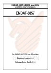
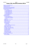
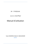
Three Piece Ball Valve
AF35(L370MF)
Series
PED Category I II
User Manual
(Operating & Maintenance instructions)
Document No SM23
Date 2004/11/5
Version 1.0
PREPARED BY
REVIEWED BY
APPROVED BY
Exclusive distributor:
DATE 2004/8/2
DATE
2004/8/2
DATE 2004/8/2
Contents
1. General Precautions
Page- 2~3
2. Product Description
Page- 3~4
3. Design Specification
Page- 4
4. Pressure Temperature Ratings
Page- 5
5. Delivery Condition and Storage
Page- 5
6. Installation and Operation
Page- 5~8
7. Put into service
Page- 8
8. Dangers of inappropriate use
Page- 8
9. Maintenance
Page- 8~10
10. Torque Data
Page- 10
11. Corrosion Data
Page- 10
1
1. General Precautions
a. Material Selection:
The possibility of material deterioration in service and the need for periodic
inspections is dependant on the line medium. Carbide phase conversion to
graphite, oxidation of ferrite materials, decrease in ductility of carbon steels at
low temperature (even in applications above –29 Deg C) are among those
items. If information about corrosion data is available; the user is advised to
refer to it to determine the suitability of material for the application.
b. Pressure-Temperature rating:
The stated Pressure -Temperature rating is based on zero pressure at ambient
temperature. Please refer to P & T rating Section 4 for working conditions. The
allowable temperature is between –20 and +180 Deg C. Do not exceed this
range.
c. Thermal expansion:
When the ball valve is in the closed condition, it is likely that the cavity within
the valve body will be filled with medium. If this medium is not released and the
valve is subject to a temperature increase, excessive pressure may build up
causing seal failure. To overcome this, our products have self-relieving seats.
The user is, however, advised not to rely on this feature and to ensure that the
pipeline design, installation and operating procedures are adequate to
overcome such potential shortcomings.
d. Static electricity
The ball valves are provided with anti-static devices on ball-stem-body. When
service conditions require electrical continuity to prevent static discharge, the
user is responsible for specifying static grounding.
e. Firesafe condition:
Generally, the application of the valve shall comply with the PressureTemperature rating range. If the risk of fire is a major issue, user is
recommended to select our fire-safe products, which have API-607 approval.
Contact the valve distributor or manufacturer for details.
f. Liquids with high fluid velocity:
When soft-seated ball valves are to be operated frequently on liquids with very
high velocity, a check should be made with the distributor or manufacturer for
appropriate advice to minimize the possibility of seat deformation, especially
when they are highly pressurized on high-temperature line.
g. Throttling service: Ball valves are not recommended for throttling service, as
both the leading edge of the ball and the seats can be damaged, causing
leakage. High fluid velocity or the presence of solid particles in suspension will
further reduce seat life
h. Do not open the bonnet or cap when the valve is under pressure. The valve is
not equipped with pressure access device. The valve should only be opened
after depressurisation.
i.
Do not touch the surface of valve on high temperature applications.
2
j. Not allowed for unstable fluid, otherwise specified with catogory III in
Declaration of conformity or/and in this user manual.
The handle has a locking feature to avoid unauthorised operation
2. Product Description
2.1 Feature
a. STANDARD type, FULL BORE ball valve.
b. Blowout proof stem.
c. Anti-static devices for ball-stem-body.
d. Heavy-duty body & end cap construction with traceable heat number.
e. Pressure balance hole in ball slot.
f. Self-relieving seat to prevent excess pressure built up.
g. Lock design on the handle is optional requirement.
2.2
Product specification
The scopes of product specifications are as following
Item No.
Nominal
Pressure
Art.3 Para3 of PED
No CE Marking
Category II
AF35
(L370MF)
PN 138
DN 8 10 15 20 25
DN 32 40 50
2.3
Material of construction
No.
Part Name
1
BODY
2
END CAP
3
BALL
4
SEAT
5
GASKET
6
THRUST WASHER
7
STEM PACKING
8
GLAND
9
BELLEVILLE WASHER
10
STEM
11
PACKING NUT
12
HANDLE WASHER
13
HANDLE NUT
14
BOLT
15
HANDLE
16
HANDLE COVER
17
LOCK SADDLE
18
O-RING
19
STOP BOLT
20
ANTI-STATIC DEVICE
Stainless Steel
Carbon Steel
EN 10213-4 1.4408
EN 10213-2 1.0619
EN 10213-4 1.4408
EN 10213-2 1.0619
EN 10213-4 1.4408
PTFE
GRAPHITE
GRAPHITE
GRAPHITE
EN 10213-4 1.4308
DIN 1.4310
EN 10213-4 1.4408
EN 10213-4 1.4308
EN 10213-4 1.4308
EN 10213-4 1.4308
EN 10213-4 1.4308
DIN 1.1191
EN 10213-4 1.4308
ZINC PLATED STEEL
PVC
EN 10213-4 1.4308
VITON
EN 10213-4 1.4308
DIN 1.1191
EN 10213-4 1.4308
3
2.4
Common dimensions
3. Design Specification
Items
Standards/Codes
Standards of Design (P-T rating)
prEN 12516-1
ASME/ANSI B16.34
Testing
EN 12266-1
ASME/ANSI B16.34
Mounting Pad
ISO 5211
Material of Casting (Body, Cap, Ball)
EN 10213-4 /1.4408
ASTM A351, A216
Bolt and Nut
ISO 3506 (A2-70)
ASTM A193, A194 (B8)
4
4. Pressure Temperature Ratings
WORK PRESSURE IN BAR
FE
PT
WORK PRESSURE IN PSIG
The pressure-temperature rating of ball valves is determined not only by the body
materials but also by the seal and trim combinations all of which are determined
by the characteristics of the service mediums and conditions. The following
general rating charts for non-shock fluid service for floating ball valves
distinguished by sizes and seating materials. Please refer to section 1, General
Precaution.
SERVICE TEMPERATURE
5. Delivery Condition and Storage
Valves are shipped in the open condition and should always be stored that way. For
incoming QC, the following should be checked:
a. Packing condition: Is there any damaged during the transportation.
b. The tightness of all external bolts should be checked.
c. Valves should be stored indoors, preferably in a climate-controlled environment
6. Installation and Operation
6.1 Handling
During installation, you must follow the procedure to handle both sides of the
bodies. If using mechanical handling, ensure the equipment is of a suitable rating
6.2 Cleaning
Regardless of the storage environment, valves should be checked for cleanliness
5
before use. If necessary, clean before installation. Clean the valves by water,
compressed air, or steam. Valves should first be cleaned in the fully-open position
and then, if further cleaning is considered necessary, in the half-open position
6.3 Valve Installation
a. Direction
Valves are bi-directional, unless marked to the contrary.
b. Position
Valves are not designed to be self-supporting, nor are they designed to be
structural; they should be properly supported.
c. Fittings
Select the correct specification of bolts to fasten the flange with pipeline. The
following table shows the fitting information.
Nominal Pipe Size
Dia of Bolt Holes
Diameter of Bolts
DN 8
¼”
9 mm - 8 hole
M8
DN 10
3/8”
9 mm - 8 hole
M8
DN 15
½”
9 mm - 8 hole
M8
DN 20
¾”
9 mm - 8 hole
M8
DN 25
1”
9 mm - 8 hole
M8
DN 32
1.1/4”
11 mm – 8 hole
M 10
DN 40
1.1/2”
13 mm -12 hole
M 12
DN 50
2”
13 mm -12 hole
M 12
Flange bolting should be conducted in accordance with sound engineering
practice, spreading the load evenly and equally. See the drawings below for the
order of bolts installation.
Round type
8 bolts
Round type
12 bolts
6
Torque data are provided in table as following table for information.
For A2 screws
Tightening torque (N-m)
70
80
Thread
diameter
Friction
coefficient
50
M8
0.2
10.1
21.4
28.7
M10
0.2
20.3
44.0
58.0
M12
0.2
34.8
74.0
100.0
d. Body hydrostatic test
Before delivery, valves are tested 1.5 times the allowable pressure at ambient
temperature in the half-open position. Pipeline testing should not exceed this
maximum
6.4 Actuator installation
The ball valves are provided with ISO 5211 mounting flanges. Following is the
flange type against sizes of the ball valves.
SIZE
Mounting Pad
DN 8
¼”
F04
DN 10
3/8”
F04
DN 15
½”
F04
DN20
¾”
F04 – F05
DN25
1”
F04 – F05
DN32
1.1/4”
F07
DN40
1.1/4”
F07
DN50
2”
F07
Actuator sizing depends on operating conditions but maximum power should
not exceed the maximum allowable operating torque of the valve Excess power
will damage the valve and possibly associated or attached equipment
6.4 Operation
a. For manual operation, turn the lever in a counter clockwise direction to close
and clockwise to open.
b. If the handle is in line with the flow direction, the valve is open. If the handle is
at 90 deg to the flow direction, the valve is closed.
c. When installing an actuator or the valve is operated with removable handle, the
user should ensure that the position of the valve is open or close. There is a slot
at the top of the stem for square type stem, as shown below
7
OPEN
C LO SE
7. Put into service
7.1 After installation in the pipeline, it is necessary to check the function of the product.
Thus, operate the valve about 3 times to ensure it operates correctly.
7.2 The whole pipeline system may be tested with a proper pressure. User shall take
care that the testing pressure shall not be exceeded 1.5 times the allowed working
pressure with the valve in the half opened position. If tested in a closed position
testing pressure should not exceed 1.1 times allowable working pressure.
7.3 After pressure testing, user shall operate the valve again about 3 times to ensure
correct operation
8. Dangers of inappropriate use
8.1 Never exceed permitted pressures or temperatures
8.2 If the product has any inappropriate use, the product may be damaged without any
immediate signs occurring. User shall change the product to avoid danger in the
future.
9. Maintenance
9.1 Maintenance frequency
The maintenance frequency is determined upon the application of the ball valve.
User shall consider the time interval depending on the fluid, flow velocity, operation
frequency, high-pressure effect and high-temperature effect etc.
9.2 Disassembly
9.2.1The user should check availability of spares kit for AF35(L370MF) with local
distributors. If not available; please do not disassemble the valve, until having
obtained spare seals and seal kits from your original supplier or nearest
Anson distributor.
9.2.2To dismantle the valve, drawings needs to be looked at and procedures as
below must be followed.
9.2.3Even if valve is removed from the pipeline medium may still be trapped under
pressure within the body cavity, therefore great care must be taken when
8
removing the valve from the pipeline or dismantling. Open valve a little and
let the fluid out slowly, great care should be taken for any poisonous or
inflammability objects.
9.2.4Turn ball in the close position before dismantle the valve. The ball cannot be
taken out from valve body if the ball is in the open or semi-open position.
9.2.5To dismantle the valve body, release the end cap carefully. Take care when
dismantling the ball to avoid the seat retainer falling from end cap.
9.2.6If lifting the ball by hoist, care must be taken to protect and avoid damaging
the ball against metal contacts. The correct position for storing the valve is to
put the open end on to the ground. This procedure protects the surface of the
ball.
9.3 Parts inspection, maintenance and replacement:
9.3.1Check the surface of ball for damge. If there is any damage on the surface,
the root cause needs to be investigated such as dirty fluid, foreign
matter…etc. Damage factors should be avoided as far as possible.
9.3.2 If the ball is found to be damaged, it must either be re-polished or replaced.
9.3.3If the ball is damaged it is likely that the seats will also be damaged.
9.3.4Check the wall thickness of valve body and cap. The minimum thickness shall
be maintained in according to EN12516-1 table 10.
9.3.5Inspect the seats for damage. Any damage will cause leakage and will
necessitate replacement of the seats.
9.3.6 Stem packing and seals are more resilient than seats and will not necessarily
require replacing. It may be prudent, however, to replace all soft seals as a
matter of good practice.To tight the gland nut, please see Section 10 for
torque data.
9.3.7Final valve inspection. Operate 10 times from open to close to ensure all the
parts are assembled correctly. It should operate smoothly and operating
9
torque should be consistent with all other valves of the same size and rating If
the torque is not the same in operation, than it may have been incorrectly
assembled. Dismantle and re-assemble. Do not use if the operation is other
than smooth
9.4 Assembly
Assembly procedure is the reverse of dismantling. Valve must be in the close
position while assembling the body and end caps. Care needs to be taken that the
stops are located at the right place; otherwise, the open and close operation will be
opposite.
10. Torque Data
Size
Stem Nut
Kgf-cm
Body&Cap
Kgf-cm
DN 8 DN 10 DN 15 DN 20 DN 25 DN 32 DN 40 DN 50
1/4
3/8
1/2
3/4
1”
1 1/4
1 1/2
2”
38
38
45
53
115
160
210
245
20
20
25
30
35
40
50
55
11. Corrosion Data
Corrosion Data is available upon request. Contact manufacturer or distributor for
further service. The corrosion data is just for information only.
10