1
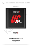
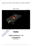
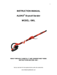
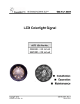
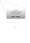
641B bulletin
2/8/05
11:04 AM
Page 1
Bulletin E-66-B
Series 641B Air Velocity Transmitter
Specifications - Installation and Operating Instructions
9-1/4
[235.0]
1/2 NPT
4-31/32
[126.21]
1-23/32
[43.66]
The Series 641B Air Velocity Transmitter uses a heated
mass flow sensor technology. It has 4 user selectable
ranges from 250 FPM to 2000 FPM with corresponding
metric ranges of 1.25 MPS to 10 MPS. The 641B provides
an isolated 4-20 mA output proportional to the velocity.
SPECIFICATIONS
Mounting: The 641B should be connected to conduit or
other connection means with the 1/2˝ NPT conduit connection. Ensure connection is installed properly so that dust
and debris can not enter housing.
Service: Air and compatible, non-combustible gases.
Accuracy:
5% FS Process gas: 32 to 122° F (0 to 50°C).
6% FS Process gas: -40 to 32°F & 122 to 176°F
(-40 to 0°C & 50 to 80°C).
Response Time: Flow: 1.5 seconds to 95% of final value
(Output filter set to minimum).
Temperature Limits: Process: -40 to 176°F (-40 to
80°C). Ambient: 32 to 140°F (0 to 60°C).
Humidity Limit: Non-Condensing.
Power Requirements: 12–35 VDC, 10–16 VAC.
Output Signal: 4-20 mA, isolated 24V source, 3 or
4-wire connection.
Output Filter: Selectable 0.5 –15 (seconds).
Loop Resistance: 600 ohms max.
Current Consumption: 300 mA max*.
Electrical Connections: Screw terminal.
Enclosure Rating: Designed to meet NEMA 4X.
Mounting Orientation: Unit not position sensitive.
Weight: 12.6 oz (357.2 g).
Airflow: The 641B is intended for use with dry air. Dust
accumulation on sensor may impair the velocity measurement and will require probe cleaning.
* A brief current transient exceeding 300 mA may be seen
on startup.
INSTALLATION
Location: Select a location where the temperature will be
within 32 to 140°F (0 to 60°C). The transmitter may be
located any distance from the receiver provided that the
total loop resistance does not exceed 600 ohms. The
probe should be located where conditions are representative of the overall environment being monitored. Avoid locations where turbulence, stagnation, or rapidly fluctuating
velocities or temperatures are present as these conditions
may affect the readings. The filter setting may be used to
average velocity readings in turbulent conditions.
Position: The transmitter is not position sensitive and may
be mounted in any orientation.
See maintenance section for additional cleaning details.
DWYER INSTRUMENTS, INC.
P.O. BOX 373 • MICHIGAN CITY, INDIANA 46361, U.S.A.
Phone: 219/879-8000
Fax: 219/872-9057
www.dwyer-inst.com
e-mail: [email protected]
641B bulletin
2/8/05
11:04 AM
Page 2
Page 2
NOTE: Where conduit connections are not made, a 1/2˝
NPT cable seal should be used to prevent contaminants
from entering the case. Where conduit connections are
made, make sure that any possible condensation within the
conduit will not flow into the transmitter housing.
ELECTRICAL CONNECTION
The 641B has been designed for easy and flexible connection to power and loop receivers. Electrical connection is
made inside the body of the device with a “Euro” style terminal block. The device features a current loop that is fully
isolated from the power source. The current loop has an
internal 24V isolated supply so no external loop power is
required. With full isolation, loop grounding is not a concern.
The input power requirements are also very flexible. The
device may be powered from either an AC or DC power
source.
3 or 4-Wire Connection
POWER SUPPLY
AC OR DC
RECEIVER
4-WIRE
3-WIRE
RECEIVER NEGATIVE
COMMON
DC SUPPLY
ONLY
(EITHER
POLARITY)
DC SUPPLY
ONLY
(EITHER
POLARITY)
RECEIVER
RECEIVER
3-WIRE
RECEIVER POSITIVE
COMMON
CAUTION: Do not exceed the specified supply voltage rating. Permanent damage not covered by the warranty may
result. Do not use an external power source on the current
loop connection.
Receiver-Transmitter Connection — The 641B is
designed as a three or four wire 4-20 ma device. The current loop output is isolated from the power supply input and
provides an internal 24-volt loop supply. With a DC power
supply, a three or four-wire connection may be used. Do not
use a three-wire connection with an AC power source. In a
three-wire connection either power supply wire may be
used as the common. The total loop resistance should not
exceed 600 Ohms.
Wire Type and Length — The wire selection for an installation is often overlooked or neglected and may contribute
to improper or even intermittent operation. In all cases
ensure that the connection meets all applicable national
and local electrical codes. Although the 4-20 mA current
loop systems are relatively immune to wire or wiring related
problems, selection of the wire for some installations will be
an important factor in ensuring satisfactory system operation. Twisted conductors will usually be immune to most
stray electric and magnetic fields and to some extent electromagnetic fields, such as interference from RF transmitters. With twisted pair wiring the current loop and the
power connections should be separate pairs. Avoid using
flat or ribbon cable that has no regular conductor twist.
Where interference is possible, it is recommended that
shielded wire be used. The shield must not be used as one
of the conductors and should be connected to ground at
only one end, generally at the power supply. Similarly, if the
installation uses conduit, the conduit should be connected
to protective ground as specified by the applicable code
and the signal wiring must not be connected to the conduit
at more than one point or as specified by the code.
The maximum length of wire connecting the transmitter
and receiver is a function of the wire resistance and receiver resistance. The total loop resistance must not exceed
600 Ohms, including the receiver resistance and wire resistance. The power supply connection must be designed so
that the worst case voltage drop due to wire resistance will
not cause the power supply voltage at the transmitter to
drop below the specified value. Provided the power supply
voltage is maintained within the specified voltage range, the
641B is not affected by variations in power supply voltage.
TRANSMITTER SETUP
The 641B has been designed for easy setup. It has five
configuration parameters that may be adjusted by the user.
These parameters are Output Filter, Range (In English or
Metric), span, 4 mA set-point and 20 mA set-point. All of
these may be adjusted at any time in the field. These
adjustments may also be easily returned to factory default.
Interior Label Diagram
CAUTION: Do not use a receiver with an internal power
supply or use an external supply in the current loop. The
current loop is powered from within the 641B. Connecting
an external supply to the current loop may destroy the
transmitter. Using an external supply voids the warranty.
Power Supply Connection — The power supply may be
either AC or DC. The DC power may be from 12 to 35 Volts.
The power connection is not polarity sensitive so the positive and negative connections may be made to either power
terminal. The AC connection may be from 10 to 16 VAC
RMS. Do not exceed 20 VAC. When selecting a transformer
please note that the specified output for transformers is at
some specified current. With a load current less than the
specified current transformer output may be significantly
higher than the specified voltage. Transformers with secondary voltages of 10 to 16 VAC are recommended.
CAUTION: Do not use transformers with a secondary voltage rating greater than 16 VAC RMS.
A set of controls and indicators are provided within the unit
consisting of the select button, enter button, adjustment
control, and six LED indicators. When operating normally,
only the RUN LED indicator will be illuminated. During the
setup operation the LED indicators will indicate the parameter selected, when it is being adjusted, and status of the
adjustment process. If the unit is left in the setup mode for
several minutes without any activity it will return to the
normal operating mode.
641B bulletin
2/8/05
11:04 AM
Page 3
Page 3
Two buttons and a potentiometer control the setup process.
The SELECT button is used to scroll between the setup
parameters.
The ENTER button allows access to each parameter for
adjustment.
The ADJUST potentiometer is used to change the value of
the parameters.
Holding the ENTER button for 2.5 seconds saves the new
parameter value.
Making Adjustments
The adjustment process has three steps: select the parameter, adjust the parameter, save the new value. These are
described in the following steps.
1. Select the parameter: Each time the SELECT button is pressed the LED indicator will advance to the next
parameter. When the last parameter, SPAN, is selected,
the next time the SELECT is pressed the unit will return
to RUN mode. Press the SELECT button until the LED
indicator illuminates the desired parameter. Press
ENTER. The selected indicator will begin to blink, showing the parameter may now be adjusted. If the unit is left
in the setup mode, after several minutes it will reset to
the operate mode.
2. Adjust the parameter: Turn the ADJUST potentiometer until the desired setting is made. This may be
adjusted using a small screwdriver or similar tool. Be
careful not to force the control past its stops or damage
will result.
3. Save the Parameter: To save the new parameter
press and hold the ENTER button. The LED indicator will
begin to flash at a faster rate. After about 2.5 seconds
all of the LED indicators will flash when the parameter is
saved. If you do not want to save the parameter press
the SELECT button without entering the parameter. The
adjusted value will be discarded and next LED indicator
will be illuminated.
Adjusting the Output Filter
The output filter may be adjusted to smooth the readings
when measuring turbulent flow. The time constant may be
adjusted from 0.5 seconds to 15 seconds. To adjust the filter time constant, select the FILTER indicator. Press ENTER
to enable adjustment. Turn the ADJUST until the desired
amount of damping is achieved. To save the value press and
hold the ENTER button until the LED indicators all flash, indicating the value was saved. To discard the adjustment press
SELECT before pressing the ENTER button.
OUTPUT FILTER RESPONSE (values in seconds)
% of Full Velocity
63%
90%
95%
99%
Filter Setting on Adjust Dial
Min.
0.5
1.1
1.5
2.3
Mid.
7.5
17.3
22.5
34.5
Max.
15
34.5
44.9
69.0
Range Selection
The range selection allows you to select one of four ranges
in either feet per minute (FPM) or meters per second (MPS).
Ranges:
FPM: 250, 500, 1000, 2000
MPS: 1.25, 2.5, 5, 10
Select the RANGE indicator by pressing ENTER when the
RANGE LED indicator is illuminated. The A,B,C LED indicators will display which range setting is currently active.
Press ENTER to enable adjustment. Turn the ADJUST until
the desired range indication is achieved. If you want to discard the adjustment press SELECT. If you want to save the
range press and hold ENTER. The RANGE LED will blink at
a faster rate for about 2.5 seconds then all of the LEDs will
flash indicating the value was saved.
The range setting is displayed with the LED indicators. The
function of these indicators is summarized on the control
label inside the unit. The following table summarizes the
indicator status for each range setting
Range/Units Run Filter Range
1
0
1
250 FPM
1
0
1
500 FPM
1
0
1
1000 FPM
1
0
1
2000 FPM
0
1
1
1.25 MPS
0
1
1
2.5 MPS
0
1
1
5 MPS
0
1
1
10 MPS
1: Indicator on
0: Indicator off
Span
A
0
0
0
0
0
0
0
0
4 mA
B
0
0
1
1
0
0
1
1
20 mA
C
0
1
0
1
0
1
0
1
641B bulletin
2/8/05
11:04 AM
Page 4
Page 4
Span Setting
The 641B has been calibrated for standard sea level conditions. As a mass flow device it will always read the air velocity for standard conditions. Density changes due to barometric or absolute pressure are not corrected automatically.
The span setting allows correction for altitude or other static pressure conditions that affect the density of the process
air. This parameter allows for a ±50% adjustment in the
span value.
To make the span adjustment you will need to know either
the absolute static pressure or the corrected velocity of the
process air. Set the air velocity to a known value, ideally
about 3/4 of the full-scale range value. Press SELECT until
the SPAN LED indicator is illuminated then press ENTER.
The SPAN LED will begin to blink. Adjust the control for the
desired velocity then press and hold the ENTER button until
all of the LED’s flash, indicating the new value was saved. If
you know the absolute static pressure you can compute the
corrected velocity using the following equation:
Vcor =
Po
Vrdg
PA
Where:
P0 is the standard pressure of 29.9 in. Hg. or 760 mm Hg.
PA is the absolute pressure reading
Vrdg is the indicated velocity
Vcor is the corrected velocity
Restoring Factory Default Settings
The 4 mA, 20 mA, and Range settings override factory
default values. To restore these to the factory default settings, start with the unit in the RUN mode. Press and hold
the ENTER button. The RUN LED indicator will begin to
blink. After about 2.5 seconds all LED indicators will flash
indicating the factory settings have been restored. Range
and Filter settings are not affected by this operation. If you
are unsure whether any have been altered, press the
SELECT button six times to sequence through all settings.
When you return to the RUN mode, the RUN LED indicator
will blink several times if either the 4 mA, 20 mA, or span
settings have been changed. The RUN LED will otherwise
remain on.
MAINTENANCE
In general the 641B should require very little maintenance.
In some installations dust may accumulate on the sensor
over time. This can be removed by carefully brushing the
probe with a small camel hairbrush. A jet of air may also dislodge the accumulated buildup. Technical grade denatured
or isopropyl alcohol may be used where the dust accumulation does not respond to brushing. Always disconnect the
power when performing a cleaning operation.
Aside from the adjustments described above, the 641B
cannot be field calibrated. Because of specialized computer instrumentation required, these units must be returned to
Dwyer Instruments for factory calibration.
4 mA Setting
To make this setting you will need a milliammeter connected in the current loop. Press SELECT until the 4 mA LED
indicator is illuminated then press ENTER. The milliammeter
will now read approximately 4.0 mA. Adjust the control for a
4.0 mA reading on the milliammeter. Press and hold ENTER
to save the new setting. Pressing SELECT before pressing
ENTER will restore the previous calibration value.
20 mA Setting
With the milliammeter connected in the current loop, press
SELECT until the 20-mA LED indicator is illuminated. Press
ENTER to begin adjustment of the 20-mA set point. The 20
mA LED will now be blinking. Adjust the control until the milliammeter reads 20.0 mA. Press and hold ENTER to save
the new setting. Pressing SELECT before pressing ENTER
will restore the previous calibration value.
©Copyright 2005 Dwyer Instruments, Inc.
Printed in U.S.A. 2/05
DWYER INSTRUMENTS, INC.
P.O. BOX 373 • MICHIGAN CITY, INDIANA 46361, U.S.A.
Phone: 219/879-8000
Fax: 219/872-9057
FR# 02-443205-20
www.dwyer-inst.com
e-mail: [email protected]