1
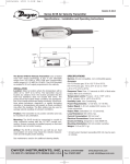
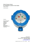
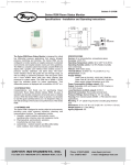
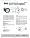
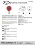
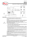
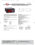
AV-670:B-32
10/1/09
2:20 PM
Page 1
Bulletin AV-670
Series 670 Hood Monitor
Specifications - Installation and Operating Instructions
DWYER INSTRUMENTS, INC.
Phone: 219/879-8000
www.dwyer-inst.com
P.O. BOX 373 • MICHIGAN CITY, IN 46361, U.S.A.
Fax: 219/872-9057
e-mail: [email protected]
AV-670:B-32
10/1/09
2:20 PM
Page 2
Operator Display Panel
Built-in AIRFLOW
SENSOR
LED indicators
Function buttons
Calibration.
ENTER- also used as
Mute button for audible
alarm
1
AV-670:B-32
10/1/09
2:20 PM
Page 3
1.67 1.67
[42.55] [42.55]
0.16 [4]
4.96
[126]
4.65
[118]
0.16 [4]
2 x FIXING HOLES
2.5 mm DIAMETER
FOR 2 x No. 4
SELF TAPPING
SCREWS PROVIDED
3.35
[85]
MOUNTING BRACKET
PANEL CUTOUT DIMENSIONS
4.65˝ x 3.35˝ [118 mm x 85 mm]
2-1/64 [51.05]
13/64 [5.08]
1-1/16
[27.10]
3-29/64 [87.88]
3-17/64 [83.06]
AIR VELOCITY MONITOR
4-9/16
[116.08]
5-45/64
[145.03]
SAFE
ENTER
4-61/64
[125.98]
ALARM
SET
SERIES 670
www.dwyer-inst.com
2
AV-670:B-32
10/1/09
2:20 PM
Page 4
SPECIFICATIONS
Service: Fume hood face velocity air flow.
Alarm Range: 30-400 FPM (0.15-2.0 m/s).
Alarm Indication: Red LED & audible alarm.
Low Air Velocity Alarm Delay: Fixed 5 secs.
Display:
Visual LEDs:
Red: Alarm.
Green: Normal.
Horn Silence: Yes-temporary and permanent.
Accuracy: Face velocity ±10%.
Operating Temperature: 55-86°F (13-30°C).
Storage Temperature: -40 to 150°F (-40 to 65°C).
Power Requirement Input: 15 VDC 500 mA; 120 VAC, 60 Hz power transformer included.
Relay Output Low Air Flow Alarm: 5 amps @ 250 VAC.
Relay Input For Night Setback: 2 wire rated for 24 VDC usage.
Sash High indication: Using a two wire micro switch or 3 wire proximity switch input,
rated for 24 VDC usage.
Comm Port: RS232- Can be connected via serial interface to LAN network.
Mounting: Semi flush, flush or surface mounted when using included bracket.
Agency Approval: CE.
3
AV-670:B-32
10/1/09
2:20 PM
Page 5
4.0 Fume Hood Installation
670
100mm
100mm
N o rm a l S as h
w o r k in g h e ig h t .
e g . 5 0 0m m
25mm
Female adapter
25mm
Male
bush
670 Face
Open to the
laboratory
25mm Tube
Fume cupboard
inner skin
Fume cupboard
outer skin
It is very important to position the Series 670 airflow sensor in the correct position to give long term
stable reading of the face velocity. Please read the INSTALLATION NOTES below and if in doubt
contact us for further advice.
Installation Notes:
1. The Series 670 must be positioned where it can "see" the room pressure of the laboratory. The
back connection spigot of the sensor is designed to accept a 25mm OD tube which should be
connected to the inner chamber of the fume hood. (This tube and fittings is known as the "vent
kit").
The ideal position for the end of the 25mm tube for most fume hoods is 100mm back from the
sash glass and 100mm higher than the normal sash opening height through the inner side wall.
2. If possible mount the sensor on the front of the fume hood and use a short length of tube. Tube
lengths of more than 1 meter or smaller diameter will restrict the airflow through the sensor.
This will lead to too much sensitivity being required to calibrate the unit which can lead to some
instability of the reading or incorrect readings at low velocities.
3. For fume hoods with a single skin side wall or a double skin with a small gap between them it
may not be possible to achieve the ideal sensing position using a flexible tube. With a single skin
side wall it is possible to fix the sensor on the outside of the fume hood and connect directly to
the inner chamber in the ideal position. This method can only be used for up to two fume hoods
when they are positioned side by side (using the two outer walls).
An alternative method is to mount the sensor on the front of the fume hood and connect using a
short flexible tube to a rigid wall tube attached to the inner side wall. The open end of this rigid
wall tube should be positioned in the ‘ideal position’, i.e., 100mm back from the sash and 100mm
higher than the normal sash opening.
Fume hoods with a high internal height can present a difficulty because the tube length to reach
the ideal position may be longer than 1 meter. In this case it is better to use a tube no longer
than 1 meter which may result in a sensing position higher than the ideal. When fitting a sensor
to a ’narrow wall’ fume hood for the first time it may be necessary to try various combinations of
rigid and flexible tube to find the best combination and position.
4. The sensor should not be mounted in a position were it is subject to drafts from the
laboratory air input or ventilation system.
4
AV-670:B-32
10/1/09
2:20 PM
Page 6
Standard Installation
Installation using Duct Connection
When using the Duct Connection method the 1/4˝ connection tube acts as a flow restrictor (due to the higher pressure in the duct). Use a 6 ft tube for pressures below 0.4 in w.c. and a 12 ft tube for higher pressures
5
AV-670:B-32
10/1/09
2:20 PM
Page 7
Wiring Diagram
Relay output
Rated 250V
5A AC1
2
Note: The Sash High alarm can operate with the Micro Switch OR the Proximity Switch.
Both connection points are available as standard.
6
AV-670:B-32
10/1/09
2:20 PM
Page 8
External Electrical Connections - The alarm unit will have the following connection points:
Input 1 - Volt free relay input - (close contact to activate the input).
This input is configured as:
NIGHT SETBACK
Output R1 - Volt free relay output - (contact closes on activation).
This input is configured as:
LOW AIR ALARM
Sash High Input - a. Connection point for Sash High micro switch. (Switch contact to
close and remain closed in Sash High condition).
b. Connection point for Sash High proximity switch. (Switch contact
to close and remain closed in Sash High condition).
Note: Use input a. OR input b. for the Sash High alarm.
Remote Airflow Sensor - Plug in connection for airflow sensor.
Note: The remote Airflow Sensor socket will only be available for units
ordered without the built-in Airflow Sensor.
Com Port - To enable connection to Laptop or PC.
Power supply - Low voltage DC power supply 15V DC.
7
AV-670:B-32
10/1/09
2:20 PM
Page 9
1.1 General Description
All systems comprise of the following components :
1 - 670 Alarm unit
1 - AC power supply
1 - 24˝ tubing
1 - IOM
1 - Vent kit
1 - Mounting bracket w/screws
Operator Features - the alarm has the following operator features :
Safe LED -
Green LED (Not flashing) will be displayed if the airflow is greater than the Low
air alarm point.
Alarm LED -
Red LED (Not flashing) will be displayed if the airflow is lower than the Low air
alarm point.
Sash High -
Red LED (Flashing) will be displayed when the Sash is raised above the max
safe working opening.
Audible Alarm -
The Audible alarm will sound ( can be muted ) in the Air Fail and the
Sash High alarm condition.
Night Set-back - When the Night Setback input is activated the Audible alarm will be muted and
the Green LED will flash on/off.
ENTER - The alarm has an Enter button - this is multi-functional as follows:
Pressing Enter momentarily when Low Air alarm is sounding will mute the alarm.
Pressing Enter momentarily when Sash High alarm is sounding will mute the alarm
and initiate a repeat timer that will re-sound the alarm if the Sash is not lowered to a safe
position before the end of the time period.
Pressing Enter for 5 secs will gain access to Calibration mode.
SET-
Press SET for 10 seconds to permanently disable the audible alarm. The audible alarm
will beep 3 times to indicate a successful permanent audible disable. If audible alarm is
permanently disabled, press SET for 10 seconds to enable. The 3 beep audible signal will
notify a successful audible enable has been programmed. Also used during the airflow
Calibration of the alarm.
8
AV-670:B-32
10/1/09
2:20 PM
Page 10
1.2 Alarm Configuration/Calibration
The alarm is supplied with a factory configuration.
The only part of the configuration that can be changed is the setting for the Sash High timer delay and
the percentage figure for the Low Air alarm point when using the two point calibration mode.
The alarm has two modes for the calibration of the airflow alarm point. These two modes are
selectable via a ‘jumper connection’ on the back of the alarm PCB. The jumper is labeled as CAL and
is situated on the edge of the PCB above the Com port.
The two calibration modes are:
a. Single Point Calibration (with the Jumper connected) - The airflow is reduced
mechanically (using balance damper or slowing down the extract fan) to the Low Air alarm
point and this air flow is ‘captured’ by the alarm. The airflow is then restored to the normal
operating value and the Low Air alarm will activate if the airflow subsequently falls to the
alarm point.
b. Two Point Calibration (with the Jumper not connected) - This is a two point calibration
method. The airflow is set to the normal operating value and this value is ‘captured’ by the
alarm and taken to be 100%. The airflow is then increased to one and a half times the
normal operating value and this value is ‘captured’ by the alarm and taken to be 150%.
The Low Air alarm will then activate if the airflow subsequently falls to 80% of the normal
operating value.
Note: For fume hoods where it is not possible to use the side wall sensor connection the sensor can
be connected directly to the extract duct using adaptors and a 1/4˝ PVC tube - see installation section
for details. Only the Single Point Calibration method can be used for this configuration.
See ‘Quick Start Installation’ below for details of the Calibration procedures.
9
AV-670:B-32
10/1/09
2:20 PM
Page 11
1.3 Start up
When unit is powered up the following sequence of events occur:
1. The 12V DC power is applied to the airflow sensor and the alarm then performs a self test
on the functions, LEDs and audible alarm (approx 2 sec) and then initiates a delay timer to
allow the airflow sensor to stabilize.
2. During the whole of the delay period all alarms and relay outputs are inhibited and the Red &
Green LEDs will be permanently ON.
3. At the end of the delay period the unit performs one of two options:
a. If the alarm calibration has been previously completed - the unit goes to normal
operating mode (Run).
b. If the unit has not been calibrated - the Red & Green LEDs will flash on/off and the
audible alarm will be muted. It is then possible to press the Enter button for 5 secs
and go into the calibration mode – (See ‘Quick Start Installation’ below for details of
the Calibration procedures).
10
AV-670:B-32
10/1/09
2:20 PM
Page 12
1.4 Events / actions
Safe airflow
• Airflow above alarm level (eg > 80 fpm).
• Green LED on.
Low airflow
• Airflow below alarm level for longer than the low air delay time (5 secs).
• Red LED on (Not flashing).
• Audible alarm sounds (Beep’ on/off every 1 sec) - can be muted via Enter pushbutton.
• Low air relay R1 operates.
Reset: - when airflow rises above Low air level for longer than the low air to safe air delay time (2
secs) the Low air alarm resets automatically.
Sash High
• When the input configured as Sash High is activated (Micro switch or Proximity switch).
• Red LED on (Flashing).
• Audible alarm sounds (‘Beep’ on/off every 1 sec).
• Audible can be muted via Enter pushbutton -- this silences the alarm and initiates a repeat
timer (factory set to 5 mins) After the delay time the alarm re-sounds (and can be re-muted).
During this time the Red LED flashes on / off.
Reset: - when Sash lowered to safe position and input de-activated.
Night set-back
• When input configured as Night set-back is activated.
• Green LED on (Flashing).
• Audible alarm muted.
Airflow Sensor Error
• The connection and each element of the airflow sensor are monitored at all times. In the
event of a problem with the sensor the audible alarm will sound using a different and
distinctive tone best described as ‘a modulating siren effect’.
• The audible alarm can only be silenced by re-connecting the sensor (if a remote sensor is
being used) or switching the power to the unit off.
11
AV-670:B-32
10/1/09
2:20 PM
Page 13
2.1 Quick Start Installation
Follow the instructions below for installing and commissioning the unit:
Before connecting the unit it is important to decide on the type of calibration that is to be used on the
installation. The two methods are described in section 1.2 Alarm Configuration/Calibration.
1. Fit the alarm to the Fume Hood using the cut-out details provided with the unit.
2. Plug in the power adapter to a 120V AC power socket and connect the flying lead to the
alarm unit - see typical connection diagram on page 6.
3. Power up the unit and wait at least 30 secs while the sensor temperature stabilizes.
During this time the Red & Green LEDs will both be on (not flashing).
If the unit has not been previously calibrated the Red & Green LEDs will begin to flash
on/off at the end of the 30 sec start up time delay but the audible alarm will not sound.
If the alarm has been calibrated it will go into normal operation.
4. Calibration:
Single Point Calibration (with CAL jumper on PCB connected).
a. Open the Sash to the normal operating height and adjust the face velocity to the
Low Air alarm value using a calibrated instrument to check the value.
b. Press and hold the Enter button for 5 secs to go into the Calibration mode. This is
indicated by both Red and Green LEDS flashing on/off together will the audible
alarm sounding (‘Beep’ on/off 4 times every 1 sec).
c. To initiate the alarm point calibration press and hold the ENTER and the SET
button at the same time. The unit will then sample the airflow for a 5 sec period
during which time the Green LED goes off and the Red LED flashes on/off. The
audible alarm continues to sound during this period and if the sampling is
successful will give a two tone beep at the end of the period and the unit will then
go automatically into the Run mode.
If the buttons are released during the sampling period or if the airflow is fluctuating
more than the pre-set value the audible alarm will give a lower frequency buzzing
sound for a short period and then go back into the calibration mode. If this occurs
re-press the ENTER and SET buttons to repeat the airflow sampling.
d. When complete re-set the airflow to the normal value and the unit will go to the
Safe running condition with the Green LED on.
The unit will now function and go into the ALARM condition if the Fume Hood
face velocity falls below the alarm value.
Use this method if the alarm is connected directly to the extract duct via the
adaptors and 1/4˝ tube.
12
AV-670:B-32
10/1/09
2:20 PM
Page 14
Calibration continued:
Two Point Calibration (with CAL jumper on PCB not connected).
a. Open the Sash to the normal operating height and adjust the face velocity to the
normal operating value using a calibrated instrument to check the value.
b. Press and hold the Enter button for 5 secs to go into the Calibration mode. This is
indicated by both Red and Green LEDS flashing on/off together with the audible
alarm sounding (‘Beep’ on/off 4 times every 1 sec).
c. To initiate the normal airflow (100%) calibration press and hold the ENTER and the
SET button at the same time. The unit will then sample the normal airflow for a 5 sec
period during which time the Green LED goes off and the Red LED flashes on/off.
The audible alarm continues to sound during this period and if the sampling is
successful will give a two tone beep at the end of the period and the unit will then
go automatically into the higher airflow calibration mode.
If the buttons are released during the sampling period or if the airflow is fluctuating
more than the pre-set value the audible alarm will give a lower frequency buzzing
sound for a short period and then go back into the calibration mode. If this occurs
re-press the ENTER and SET buttons to repeat the airflow sampling.
d. The higher airflow calibration mode is indicated by both Red and Green LEDS
flashing on/off together with the audible alarm sounding (‘Beep’ on/off for 2 secs
every 10 secs).
Close the Sash down until the face velocity rises to one and a half times the normal
operating value used in a. above using a calibrated instrument to check the value.
To initiate the higher airflow (150%) calibration press and hold the ENTER and the
SET button at the same time. The unit will then sample the higher airflow for a 5 sec
period during which time the Green LED goes off and the Red LED flashes on/off.
The audible alarm continues to sound during this period and if the sampling is
successful will give a two tone beep at the end of the period and the unit will then
go automatically into the Run mode.
If the buttons are released during the sampling period or if the airflow is fluctuating
more than the pre-set value the audible alarm will give a lower frequency buzzing
sound for a short period and then go back into the calibration mode. If this occurs
re-press the ENTER and SET buttons to repeat the airflow sampling.
The unit will now function and go into the ALARM condition if the Fume
Hood face velocity falls below 80% of the normal operating value.
13
AV-670:B-32
10/1/09
2:20 PM
Page 15
2.2 Calibration Notes:
1. The two calibration methods are intended to give the installer two options for calibrating the
alarm.
2. Using the Alarm Point Capture method it is necessary to adjust the face velocity on the fume
hood using a mechanical damper (or fan speed control if available) to the desired alarm point
and this is sampled by the unit. It is then necessary to re-adjust the face velocity back to the
normal operating value. This method produces a very accurate alarm point at a fixed value
but involves getting access to the ductwork or fan speed controller.
3. The second method of Two Point Capture is slightly more involved but does not require any
access to the ductwork or fan speed controller and is generally a quicker solution.
The principal behind this method is as follows:
The output from the airflow sensor is linear over the normal operating range of the face
velocities on fume hoods. If we therefore capture the airflow sensor output at two known
points we can then calculate the alarm point and give an alarm when the airflow falls below
this value. However because the 670 does not have a digital display of the face velocity we
can not enter particular values into the alarm. For this reason we take the normal operating
value of the face velocity with the sash open to the max safe working opening and call this
100% -- this point is captured during the first sample. Then by closing the sash it is possible
to create a face velocity which is one and a half times the normal operating value, i.e., 150%
- this point is captured during the second sample. We then use these two values to calculate
the sensor output at 80% and this becomes the Low Air alarm point. The actual value of the
normal operating face velocity is not important and in each case the alarm point will be 80%
of this value.
For example:
A normal face velocity of 100 fpm would give an alarm point of 80 fpm
A normal face velocity of 80 fpm would give an alarm point of 64 fpm
4. The face velocity readings on the open sash may vary at different points on the measuring
grid by up to 20 fpm. This is quite acceptable in terms of the fume cupboard performance so
long as no individual point is below the designated Low Air alarm point. The figure entered for
the calibration point can be taken as the average value of all the measuring grid readings or
could be taken as the individual lowest point on the grid. For most fume hoods this low point
is on the bottom row in the center and is a convenient position to measure and for future
reference when checking the alarm during annual maintenance.
5. Take time when measuring the face velocities for the calibration procedure to allow for the
velocities across the open sash to stabilize. If the velocities are changing or are turbulent
during the sampling period the alarm will detect this and give a low frequency buzz at the
end of the sample indicating that the sample must be repeated.
14
AV-670:B-32
10/1/09
2:20 PM
Page 16
MAINTENANCE
Upon final installation of the Series 670 Hood Monitor, no routine maintenance is required. The Series
670 is not field serviceable and should be returned if repair is needed (field repair should not be
attempted and may void warranty). Be sure to include a brief description of the problem plus any relevant application notes. Contact customer service to receive a return goods authorization number
before shipping.
©Copyright 2009 Dwyer Instruments, Inc.
Printed in U.S.A. 10/09
FR# 443751-00
DWYER INSTRUMENTS, INC.
Phone: 219/879-8000
www.dwyer-inst.com
P.O. BOX 373 • MICHIGAN CITY, IN 46361, U.S.A.
Fax: 219/872-9057
e-mail: [email protected]