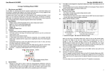
1
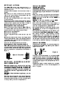
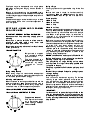
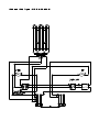
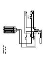
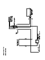
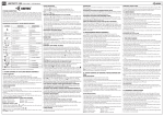
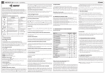
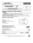
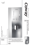
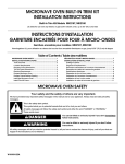
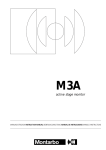
Installation and Servicing Instructions
for
LD46, LD48, LD50 and LD56 FRYERS
LD60 Chip Scuttle
LD69 Pasta Cooker
The installer must ensure that installation of the unit(s) is in confornity with regulations in force at the time.
For the UK, particular attention requires to be paid to:BS7671 IEE Wiring Regulations
Electricity at Work Regulations
Health and Safety at Work Act
Fire Precautions Act
The unit has been CE-marked on the basis of compliance with the Low Voltage and EMC Directives for the
voltage stated on the data plate.
WARNING: THIS APPLIANCE MUST BE EARTHED!
Preventive Maintenance Contract
In order to obtain maximum performance from the equipment, we would recommend that a maintenance
contract be arranged with Serviceline. Visits may then be made at agreed intervals to carry out adjustments
and repairs. A quotation for this service will be provided upon request. Contact Serviceline as detailed below:Tel: 01438 363 000
Fax: 01438 369 900
WEEE Directive Registration No. WEE/DC0059TT/PRO
At end of unit life, dispose of appliance and any replacement parts
in a safe manner, via a licenced waste handler.
Units are designed to be dismantled easily and recycling of all
material is encouraged whenever practicable.
Falcon Foodservice Equipment
Wallace View, Hillfoots Road, Stirling. FK9 5PY. Scotland
e-mail: [email protected]
T100320 Ref. 4
a/n
a/n
a/n
a/n
A5
A31
gnitaR rewoP
Wk6
Wk6 x 2
Wk57.2
Wk57.2 x 2
Wk52.1
Wk57.2
.lC raeR/ediS
mm051
mm051
mm051
mm051
mm051
mm051
ecnaraelC lacitreV
mm009
mm009
mm009
mm009
mm006
mm006
thgieH
mm569
mm569
mm513
mm513
mm513
mm513
htpeD
mm006
mm006
mm006
mm006
mm006
mm006
htdiW
mm003
mm006
mm003
mm006
mm054
mm003
ledoM
reyrF gnidnatseerF 64DL
reyrF gnidnatseerF 84DL
reyrF potretnuoC 05DL
reyrF potretnuoC 65DL
elttucS pihC 06DL
rekooC atsaP 96DL
1 elbaT noitamrofnI noitallatsnI lacinhceT
gnitaR esuF
CA N2 V004 ro CA V032 ta sgnitaR rewoP
tinU gnidnatseerF = F
tinU potretnuoC = C
SECTION 1 - SITING
LD50 and LD56 FRYERS
The PRO-LITE models have been designed in a
modular form which consists of base, counter and
free-standing units.
Information which relates to individual models is listed in
Table 1.
Free-standing and base models should be installed
upon a firm, level surface and adjustable feet are
provided for levelling purposes.
Counter units must be positioned upon a table, counter
or similar surface.
Vertical and horizontal clearances required from top and
sides of a particular unit to any overlying combustible
surface (ie wall, partition, etc) are listed in Table 1.
Relevant fire regulations must be complied with.
Mounting Counter Units upon an Oven
When mounting a counter unit upon a PRO-LITE oven,
it is recommended that units which carry liquids, i.e.
fryers and bains maries, are secured as follows:
Remove oven outer back panel.
Remove oven crown plate.
Position unit(s) which require to be secured upon the
oven.
Secure hob unit(s) to oven through side flange centre
holes into the threaded inserts in the base(s) of the hob
unit(s). Use fixings provided (packed separately) and
replace oven back panel.
The unit is now ready for electrical connection.
Mounting Counter Units upon a Hotcupboard
PRO-LITE hotcupboards are designed to be used in
conjunction with counter models. Assembly is achieved
by means of two shouldered fixings being applied to a
top unit underside from inside a base unit as detailed in
Figure 1.
Figure 1 - Front View
SECTION 2 - ELECTRICAL SUPPLY
AND CONNECTION
Electrical
ratings
are
as
stated
on
the
unit
data
plate. The listing in Table 1 is based on standard UK
specification
as
at
230V
appropriate.
accordance
with
~, 400V 2N~ or 400V 3N~
Wiring
the
must
be
regulations
executed
listed
in
in
this
booklet.
WARNING:
Each
individual
appliance
must
be
earthed!
After completion of installation, the method of operation
should be demonstrated to responsible person(s).
The isolating switch location, for use in an emergency
or during cleaning should also be pointed out.
LD60 CHIP SCUTTLE
LD69 PASTA COOKER
These models are designed to be connected to a single
phase AC supply using the 2 metre mains lead fitted as
standard.
Wires are coloured in accordance with the following
code and should be connected to the plug as follows:
EARTH to terminal marked E or coloured GREEN or
GREEN/YELLOW.
NEUTRAL to terminal marked N or coloured BLACK.
LIVE to terminal marked L or coloured RED.
Units which receive power from a plug, adaptor or
distribution board must be individually protected by a
fuse with an appropriate rating. (See Table 1)
For models with two mains leads, each lead requires to
be protected by a fuse with an appropriate rating.
(See Table 1)
Any replacement supply cable must be 1.5mm2, cord
code designation 245 IEC 57 (CENELEC H05 RN-F).
For internal connection, outer sheathing must be
stripped 140mm from the cable end. The live and
neutral conductors must be trimmed so that the Earth
conductor is longer by 50mm. Pass inlet cable through
the rear panel cord grip and ensure that cable is routed
without leaving excessive free length inside appliance.
LD46 and LD48 FRYERS
These models are supplied for use on 2 phases of a
3 phase and neutral AC supply. Ratings are stated on
appliance data plate.
Supply Cables
Link Wire
Figure 2
The fryers may also be operated on a single phase AC
supply by fitting a bridging link as detailed in Figure 2.
When a unit is connected to a single phase AC supply,
data plate information must be amended to indicate the
correct voltage supply and the phase power split should
be deleted.
The electrical supply must be installed using a suitable
isolating switch with a minimum contact separation of
3mm in all poles.
The fryers may also be operated on a single phase
AC supply by fitting two bridging links as detailed in
Figure 3.
When a unit is connected to a single phase AC supply,
data plate information must be amended to indicate the
correct voltage supply and the phase power split should
be deleted.
The electrical supply must be installed using a suitable
isolating switch with a minimum contact separation of
3mm in all poles.
Using a Fryer
Thoroughly clean and dry pan before using for the first
time.
Ensure drain valve is closed, i.e. handle turned fully
clockwise on LD46 and LD48 models and fully left on
LD50 and LD56 models. Fill pan with oil to level mark.
Pan Capacities
LD46 - 8 litres
LD48 - 2 x 8 litres
LD50 - 7 litres
LD56 - 2 x 7 litres
SECTION 3 - USING AND CLEANING
PRO-LITE UNITS
IMPORTANT: GENERAL NOTES ON CLEANING
Disconnect
unit
from
electricity
supply
prior
to
cleaning
Never
use
panels.
A
a
coarse
soft
abrasive
cloth
with
a
to
clean
warm
exterior
water
and
detergent solution is sufficient.
Never attempt to steam clean a unit or hose it down
with a jet of water.
LD60 CHIP SCUTTLE
Chip scuttle is supplied
with removable storage
pans and drainer.
The lamp is heated by a
500W halogen heat lamp controlled by switch
located on control
panel.
Set thermostat to desired temperature and leave unit to
heat up. When selected temperature is reached, the
amber neon will go out to indicate that unit is ready to
use. When oil temperature drops, i.e. when food is
immersed in oil, the thermostat will automatically
restore current to elements.
Before draining pan or removing elements for cleaning,
switch unit off at mains isolating switch. All models are
fitted with safety switches to cut off power if element box
is raised from pan when power remains on.
Repositioning box upon main body automatically
restores power. A re-settable safety thermostat is
located on underside of element box to protect against
any overheating situation. Attention is drawn to the
following safety related points:NEVER switch unit on unless pan is filled with oil.
Before draining pan or removing element box for
cleaning, isolate fryer at main switch.
The
possibility
of
surge
boiling
exists
when
over-wet food or a larger than recommended load
is applied to the pan.
The pan may catch fire if oil is below minimum level
mark.
Using a Chip Scuttle
Used oil has a reduced flashpoint making it prone
When storing chips, it is not advisable to keep them
covered for longer than is absolutely necessary as this
will cause the potato to become soggy.
Cleaning a Chip Scuttle
Clean containers as soon as possible after use with hot
water and detergent. Soap filled pads may be used to
remove stubborn deposits. Avoid leaving empty used
containers in the unit. Food deposits may bake on.
to surge boiling.
Cleaning a Fryer
The unit should be cleaned regularly. To facilitate
cleaning of pan interior, elements and element box
may be lifted from pan. When the worst of the food
particles and oil have been removed from pan and
elements, replace box. Fill pan to level mark with water/
detergent solution, take care not to let solution overflow.
Drain pan, thoroughly rinse and dry.
LD46 and LD48 FREE STANDING FRYERS
IMPORTANT:
LD50 and LD56 COUNTERTOP FRYERS
In the event of no power being available to the
element box check that it is set properly on the
main body. If this is not successful then reset safety
Temperature Control
The fryers are controlled
by a thermostat which
offers settings between
130 and 190oC.
stat by pressing red button on the underside of the
element box.
LD69 PASTA COOKER
SECTION 4 - SERVICING
LD60 CHIP SCUTTLE
Unit Controls
A temperature control and
indicator neons monitor
operation of unit.
ENSURE UNIT IS ISOLATED AT MAINS SUPPLY
SERVICE ACCESS
Base Plate
Upturn unit and rest it at edge of worksurface with rear
upstand overhanging edge.
Undo base plate fixings to remove base plate.
Using a Pasta Cooker
Ensure drain valve is closed, ie. lever is fully left and
safety catch has dropped into position.
Fill pan with 10 litres of water (to top level mark on
element guard).
If a basket is immersed, maximum fill mark corresponds
to top of perforated section. Take care not to overfill
basket.
FUNCTIONAL COMPONENTS
Temperature Control.
unless pan is filled with water. The minimum level is
Remove base panel.
Remove control knob.
Remove electrical connections, noting their positions.
For units with thermostat, carefully remove phial from
retaining clips and clear structure.
Undo fixings that secure control to panel and remove.
Replace in reverse order.
indicated on element guard.
Elements
Set control to desired temperature and allow water to
heat. If setting is below 100oC, amber neon will go out.
Power to element is cut when temperature is reached.
When temperature drops, control will automatically
restore power to elements and amber neon will light.
If setting is beyond 100oC mark, water will boil
continuously and amber neon will remain lit at all times.
Top up water regularly to avoid well from boiling dry,
this could damage unit. Regular water replacement of to
reduce starch build-up is recommended when cooking
pasta. Warning - Take extreme care when draining
Remove base plate.
Undo electrical connections, noting positions.
Undo element fixings and remove.
Replace in reverse order.
WARNING
Never,
under
any
circumstances,
switch
unit
on
hot water!
A safety switch is provided to cut-off power to elements
if element box is raised from pan. Box repositioning will
automatically restore power. In the event of power not
being available to element, check box is properly
located upon main body.
WARNING
not
leave
Remove base plate.
Remove electrical connections at terminal block, noting
positions.
Undo fixings which secure block to unit and remove.
Replace in reverse order.
Cable
Important Note
Do
Terminal Block
baskets
in
boiling
water
for
an
unnecessary period of time as the handles quickly
become VERY HOT!
Cleaning a Pasta Cooker
Isolate unit at mains supply.
Attach spout to drain valve. To open valve, lift safety
catch at pan front and move lever to right. Drain water
from pan into an appropriate vessel.
Lift off element box to gain access to pan. Wipe empty
pan and remove food debris. Also remove any debris
which may be present on elements. Reposition element
box and refill pan with a water detergent solution to level
mark indicated on element guard.
Drain pan. Thoroughly rinse and dry before use.
Retain spout in clip provided on lid underside when
not in use.
Remove base plate.
Undo mains cable cord grip at unit rear.
Undo electrical connections at terminal block and
remove cable.
Replace in reverse order. Ensure cable is fed through
securing clamp and pulled taut before tightening clamp.
LD46, LD48, LD50 and LD56 FRYERS
LD69 PASTA COOKER
SERVICE ACCESS
SERVICE ACCESS
ENSURE UNIT IS ISOLATED AT MAINS SUPPLY
ENSURE UNIT IS ISOLATED AT MAINS SUPPLY
Outer Back Panel
Outer Back Panel
Remove lid, baskets and fish plate. Lift element box
from pan.
Remove box rear panel by undoing fixings on box
underside.
Remove lid and baskets. Lift element box from pan.
Remove box rear panel by undoing fixings on box
underside.
FUNCTIONAL COMPONENTS
Control Thermostat
Remove back panel of element box.
Remove electrical connections, noting positions.
Undo fixings which secure thermostat to control panel.
Remove phial seal at control panel entry point and
withdraw phial.
Replace in reverse order and ensure phial seal and
electrical insulation sheet/phial cover are secured in
position.
Neon Indicator
Remove back panel from element box.
Remove electrical connections.
Undo neon retaining nut and remove neon.
Microswitch
Remove back panel from element box.
Remove electrical connections.
Undo the fixings which secure switch to panel bracket.
Replace in reverse order and ensure electrical insulation sheet is securely in position.
Safety Thermostat
Remove back panel from element box.
Remove electrical connections.
Undo the fixings which secure the switch to the panel
bracket.
Replace in reverse order and ensure that the electrical
insulation sheet is securely in position.
Elements
Remove back panel from element box.
Remove electrical connections, noting their positions.
Remove retaining nuts and withdraw elements.
Replace in reverse order.
Terminal Block
Remove back panel from element box.
Undo electrical connections, noting their positions.
Undo fixings which secure block to panel and remove
block.
Replace in reverse order.
Mains Power Cable
Remove back panel from element box.
Remove electrical connections, noting their positions.
Undo cable cord grip at panel entry and withdraw cable.
Replace in reverse order.
FUNCTIONAL COMPONENTS
Control Thermostat
Remove outer back panel.
Remove electrical connections, noting positions.
Undo fixings which secure thermostat to element box.
Remove phial seal at element box entry and withdraw
phial.
Replace in reverse order and ensure phial seal and
electrical insulation sheet/phial cover are secured in
position.
Neon Indicator
Remove outer back panel from element box.
Remove electrical connections.
Undo neon retaining nut and remove neon.
Microswitch
Remove outer back panel from element box.
Remove electrical connections.
Undo fixings which secure switch to panel bracket.
Replace in reverse order. Ensure electrical insulation
sheet is securely in position.
Elements
Remove outer back panel from element box.
Remove electrical connections, noting the positions.
Undo retaining nuts and withdraw elements
Replace in reverse order.
Terminal Block
Remove outer back panel from element box.
Undo electrical connections, noting the positions.
Undo fixings which secure block to panel and remove
block.
Replace in reverse order.
Mains Power Cable
Remove outer back panel from element box.
Remove electrical connections, noting positions.
Undo cable cord grip at panel entry and withdraw cable.
Replace in reverse order.
PRO-LITE SHORT SPARES
Fryers
735110060
Red Neon
735110070
Terminal Block L1 & N
735110100
Supply Cable
735120010
Control Knob
735110012
Thermostat
735120034
Safety Thermostat
735120014
Amber Neon
735120015
Element (2.75kW)
735120016
Element (6kW)
735120017
Element (9kW)
735120018
Chip Basket (200mm)
735120019
Chip Basket (160mm)
735120020
Drain Valve
735120021
Door Hinge (LD46, 48)
735120022
Strainer
735120023
Door Handle
735120024
Microswitch Kit - Single (LD50, 56)
735120027
Terminal Block (L2 & L3)
Chip Scuttle
735230001
Control Knob
735230002
Thermostat
735230003
Element
735110060
Red Neon
735240001
Lamp Switch (LD60)
735240002
Lamp (5000W LD60)
735110100
Supply Cable
Pasta Cooker
735250001
Control Knob
735110060
Red Neon
735120014
Amber Neon
735250003
Microswitch
735120015
Element
735250004
Thermostat
735250005
Basket Liner
735250006
Basket Portion
735110100
Supply Cable
LD46 and LD48 Fryers - WIRING DIAGRAM
9
8
HTRAE
21
11
01
YLPPUS EROC 3
MARGAID GNIRIW
sreyrF 65DL dna 05DL
MARGAID GNIRIW
ELTTUCS PIHC 06DL
LD69 Pasta Cooker - WIRING DIAGRAM