1
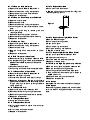
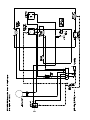
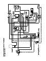
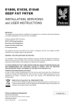
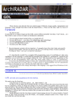
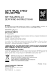
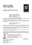
E7202S/E7202 BE1 and BE2
E7202 BF1 and BF2
CONVECTION OVEN
INSTALLATION and
SERVICING INSTRUCTIONS
IMPORTANT
The installer must ensure that the installation of the appliance is in conformity with these instructions and
National Regulations in force at the time of installation. Particular attention MUST be paid to -
BS7671 IEE Wiring Regulations
Electricity at Work Regulations
Health And Safety At Work Act
Fire Precautions Act
This appliance has been CE-marked on the basis of compliance with the Low Voltage and EMC Directives for
the voltages stated on the Data Plate
WARNING -THIS APPLIANCE MUST BE EARTHED
On completion of the installation these instructions should be left with the Engineer-in-Charge for reference
during servicing. Further to this, The Users Instructions should be handed over to the User, having had a
demonstration of the operation and cleaning of the appliance.
IT IS MOST IMPORTANT THAT THESE INSTRUCTIONS BE CONSULTED BEFORE INSTALLING AND
COMMISSIONING THIS APPLIANCE. FAILURE TO COMPLY WITH THE SPECIFIED PROCEDURES MAY
RESULT IN DAMAGE OR THE NEED FOR A SERVICE CALL.
PREVENTATIVE MAINTENANCE CONTRACT
In order to obtain maximum performance from this unit we would recommend that a Maintenance Contract be
arranged with SERVICELINE. Visits may then be made at agreed intervals to carry out adjustments and
repairs. A quotation will be given upon request to the contact numbers below.
WEEE Directive Registration No. WEE/DC0059TT/PRO
At end of unit life, dispose of appliance and any replacement
parts in a safe manner, via a licenced waste handler.
Units are designed to be dismantled easily and recycling of all
material is encouraged whenever practicable.
Falcon Foodservice Equipment
HEAD OFFICE AND WORKS
Wallace View, Hillfoots Road, Stirling. FK9 5PY. Scotland.
SERVICELINE CONTACT PHONE - 01438 363 000
FAX - 01438 369 900
T100677 Ref. 3
Warranty Policy Shortlist
Warranty does not cover :-
Correcting faults caused by incorrect installation of a product.
Where an engineer cannot gain access to a site or a product.
Repeat commission visits.
Replacement of any parts where damage has been caused by misuse.
Engineer waiting time will be chargeable.
Routine maintenance and cleaning.
Gas conversions i.e. Natural to Propane gas.
Descaling of water products and cleaning of water sensors where softeners/conditioners are not fitted, or are
fitted and not maintained.
Blocked drains.
Independent steam generation systems.
Gas, water and electrical supply external to unit.
Light bulbs.
Re-installing vacuum in kettle jackets.
Replacement of grill burner ceramics when damage has been clearly caused by misuse.
Where an engineer finds no fault with a product that has been reported faulty.
Re-setting or adjustment of thermostats when unit is operating to specification.
Cleaning and unblocking of fryer filter systems due to customer misuse.
Lubrication and adjustment of door catches.
Cleaning and Maintenance
Cleaning of burner jets
Poor combustion caused by lack of cleaning
Lubrication of moving parts
Lubrication of gas cocks
Cleaning/adjustment of pilots
Correction of gas pressure to appliance.
Renewing of electric cable ends.
Replacement of fuses
Corrosion caused by use of chemical cleaners.
SECTION 1 - INSTALLATION
SECTION 2 - SERVICING and
MAINTENANCE
UNLESS OTHERWISE STATED, PARTS WHICH Warning
HAVE BEEN PROTECTED BY THE
MANUFACTURER ARE NOT TO BE ADJUSTED BEFORE ATTEMPTING TO UNDERTAKE ANY
MAINTENANCE TASK. ISOLATE THE POWER AT
BY THE INSTALLER
THE MAIN SWITCH AND TAKE STEPS TO
1.1 MODEL NUMBER, NETT WEIGHTS
ENSURE THIS CANNOT BE INADVERTENTLY
and DIMENSIONS
SWITCHED ON.
MODEL
WIDTH DEPTH HEIGHT WEIGHT WEIGHT
mm
mm
mm
kg
lbs
E7202S
667
570
550
50
110
E7202 BE1
667
570
550
50
110
E7202 BE2
667
570
550
50
110
E7202 BF1
667
570
550
50
110
E7202 BF1
667
570
550
50
110
Undo two fixings on underside of oven until location
pins allow panel to drop forward.
2.1.2 To Remove Rear Panel
a) Slacken fixings behind elongated slots at top of
panel.
b) Lift panel clear of these fixings.
c) Replace in reverse order.
2.1.3 To Remove Outer Casing
1.2 SITING
The units are suitable for installation upon any flat,
horizontal surface. Adjustable feet to facilitate
levelling within a limited range. Position oven in
desired location and use a suitable spanner to level.
Sufficent clearance should be left around unit to allow
turning for maintenance purposes.
1.3 ELECTRICAL SUPPLY and CONNECTION
These ovens are designed to be connected to a
single phase 230V/50hz AC supply. The unit power
rating is 2.65kW. The mains lead is fitted with a
moulded fused plug to BS1363 with 13 amp fuse
fitted. The mains lead wires are coloured in
accordance with the following code:
Green and Yellow
Blue
Brown
2.1 OVEN CONTROL PANEL
2.1.1 Control Panel
EARTH
NEUTRAL
LIVE
These wires should be connected as follows:
EARTH to terminal marked E
NEUTRAL to terminal marked N
LIVE to terminal marked L
Warning - This appliance MUST be earthed!
Any replacement supply cable must be 1.5mm2, cord
code designation 245 IEC 57 (Cenelec H05 RN-F).
For internal connection, outer sheathing must be
stripped 140mm from cable end. Live and Neutral
conductors must be trimmed so that earth conductor
is longer by 50mm. Pass inlet cable through rear
panel cord grip and ensure cable is routed without
leaving excessive free length inside unit.
1.4 INSTRUCTION TO USER
Upon completion of installation, the correct method of
operation should be demonstrated to kitchen staff.
Location of the main isolating switch should also be
indicated, to be used in event of an emegency or
during cleaning.
a) Remove rear panel. See Sections 2.1.2.
b) Undo fixings that secure casing to base.
c) Remove top and bottom hinge fixing screws.
d) Pull casing sides away from base and lift casing.
e) Replace in reverse order.
2.1.4 To Remove Oven Back Baffle
a) Remove oven shelves.
b) Raise shelf hangers from keyhole slots and
remove.
c) Slacken back baffle fixing screws.
d) Raise baffle on keyhole slots to remove.
e) Replace in reverse order.
2.1.5 To Remove Elements
a) Remove back baffle. Refer to Section 2.1.4.
b) Remove rear panel as detailed in Section 2.1.2.
c) Undo element connections at oven rear.
d) Remove fixings at rear of oven cavity.
e) Withdraw element.
f) Replace in reverse order and ensure earth tab is
connected.
2.1.6 To Remove Fan
a) Remove baffle. Refer to Section 2.1.4.
b) Remove rear panel. Refer to Section 2.1.2.
c) Undo fan wires.
d) Remove earth lead.
e) Undo impeller retaining nut (LH thread) and
remove impeller.
f) Undo fixings that secure motor to oven rear and
withdraw.
g) Replace in reverse order.
2.1.7 To Remove Neon Indicators
a) Open control panel. Refer to Section 2.1.1.
b) Remove connections, noting their positions.
c) Remove securing nut and withdraw neon.
d) Replace in reverse order.
2.1.15 To Replace Door Stud
a) Undo locknut and remove stud.
b) Replace stud and adjust as detailed in Figure 1
before tightening locknut.
2.1.8 To Remove Cook Thermostat/fan Switch
a) Open main control panel.
b) Remove control knob.
c) Remove connections, noting their positions.
d) Undo fixings which secure thermostat to control
panel.
e) Undo phial guard fixing to remove guard and
retaining brackets.
f) Feed phial back through oven side hole.
g) Remove extension spindle and phial sleeving.
h) Replace in reverse order.
2.1.9 To Remove Timer
a) Open control panel. Refer to Section 2.1.1.
b) Remove connections, noting their positions.
c) Remove control knob.
d) Remove fixings which secure timer to control
panel.
e) Replace in reverse order.
2.1.10 Hold Thermostat (when fitted)
a) Remove outer casing as detailed in Section 2.1.3.
b) It is possible to adjust hold thermostat temperature
between 75 and 85oC by means of the spindle.
To Remove
c) Disconnect electrical leads.
d) Undo fixings which secure thermostat to bracket.
2.1.11 To Remove Power Input Cable
a) Remove rear panel. Refer to Section 2.1.2.
b) Slacken cable securing clamp.
c) Undo terminal block and earth post nut fixings.
d) Replace in reverse order. Replace plug and cable
type as detailed in Section 1.3. Ensure cable is fed
through securing clamp and pulled tight before
clamp is secured.
2.1.12 To Remove Buzzer
a) Open control panel, refer to Section 2.1.1.
b) Disconnect buzzer wiring noting wire positions.
c) Remove fixing which secures buzzer to bracket.
d) Replace in reverse order.
2.1.13 To Replace Door Seal
a) Unclip seal from front frame.
2.1.14 To Replace Door Catch
a) Drill out pop rivets which secure inner and outer
door panels.
b) Drill out rivets which secure catch.
c) Replace in reverse order.
Figure 1
2.1.16 To Remove Oven Light (When Fitted)
a) Remove RH shelf hanger.
b) Undo lamp cover fixing screws.
c) Open control panel.
d) Undo lamp wiring connections.
e) Unclip lamp housing from aperture.
f ) Replace in reverse order.
2.1.17 To Remove Light Switch (When Fitted)
a) Open control panel. Refer to Section 2.1.1.
b) Slacken switch retaining nut.
c) Unscrew bezel and remove push button.
d) Replace in reverse order.
2.1.18 To Remove High Temperature Limit Device
a) Remove control panel as detailed in Section 2.1.
b) Remove connections, noting positions.
c) Undo fixings that secure device to base panel.
d) From inside oven, remove phial guard located at
top RH side of unit.
e) Feed phial back through oven side hole.
f) Replace in reverse order.
2.1.19 Service
Contact Serviceline number indicated on title page.
2.1.20 Spares
When ordering spares, please quote model number,
serial number and voltage as indicated on unit data
plate.
)33963WA : oN gniwarD(
margaiD gniriW - snevO noitcevnoC 2EB/1EB/S2027E
)11964WA : oN gniwarD(
margaiD gniriW - snevO noitcevnoC 2FB & 1FB 2027E