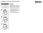
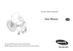
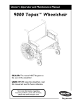
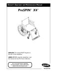
1
Merits
S2354/S2454 series
Service Manual
Nov.1.2006 V1
Index
1. Introduction ................................................................................. P1
2. Service Guide ............................................................................... P1
2.1. How to replace or repair the seat assembly.............................................P1
2.1.1. To remove seat body assembly................................................................................. P1
2.1.2. To replace the seat base plate ................................................................................... P1
2.1.3. To replace the slide .................................................................................................. P2
2.1.4. To replace seat body ................................................................................................ P2
2.1.5. To replace the arm pad............................................................................................. P3
2.1.6. To replace the seat post............................................................................................ P4
2.2. How to replace or repair the batteries.....................................................P5
2.2.1. To replace the batteries ............................................................................................ P5
2.3. How to replace or repair the front section assembly ..............................P6
2.3.1. To replace the front shroud ...................................................................................... P6
2.3.2. To replace the front wheel assembly ........................................................................ P8
2.3.3. To replace the front tire............................................................................................ P10
2.3.4. To replace the front bumper ..................................................................................... P10
2.3.5. To replace the steering mechanism........................................................................... P11
2.3.6. To replace the front frame........................................................................................ P12
2.4. How to replace or repair the rear section assembly................................P13
2.4.1. To replace the rear shroud........................................................................................ P13
2.4.2. To replace the transaxle assembly ............................................................................ P13
2.4.3. To replace the rear anti-tipper assembly ................................................................... P14
2.4.4. To replace the rear wheel assembly .......................................................................... P14
2.4.5. To replace the rear tire ............................................................................................. P15
2.4.6. To replace the controller .......................................................................................... P15
2.4.7. To replace the fuse ................................................................................................... P15
2.4.8. To replace the rear frame ......................................................................................... P16
2.5. How to replace or repair the tiller assembly ...........................................P16
2.5.1. To remove the tiller assembly .................................................................................. P16
2.5.2. To remove the top & bottom shroud assembly ......................................................... P16
2.5.3. To replace the PCB .................................................................................................. P17
2.5.4. To replace the key and key switch............................................................................ P18
2.5.5. To replace the buzzer ............................................................................................... P18
2.5.6. To replace the indicator light.................................................................................... P18
2.5.7. To replace the horn button switch ............................................................................ P19
2.5.8. To replace the speed knob and potentiometer (adjust) .............................................. P19
2.5.9. To replace the battery level indicator........................................................................ P19
2.5.10. To replace the throttle lever.................................................................................... P19
2.5.11. To replace the potentiometer (movement) .............................................................. P20
2.5.12. To replace the charger plug-in unit ......................................................................... P20
The numbers shown in this service manual is just for reference. The part
numbers should be in accordance with current exploded drawing
1. Introduction
The purpose of this manual is to provide dealers and/or distributors with the
product information and instructions that are required for servicing the
S2354/S2454 scooter.
2. Service Guide
The S2354/S2454 scooter consists of four main parts:
n Seat Assembly
n Batteries
n Body Assembly (Front section ; Rear section)
n Tiller
2.1. How to replace or repair the seat assembly
The Seat assembly includes seat body, seat base plate, slide and left /
right armrests.
2.1.1. To remove seat body assembly
Pull the swivel lever (3.06) under the seat up to unlock it and rotate
the seat a little bit to the position where you can feel the seat rotate
freely. Lift the seat body assembly upward. [see Illus. 01]
Illus. 01
2.1.2. To replace the seat base plate
◆ When you should replace the seat base plate?
◇ If the seat base plate is deformation.
◇ If the seat base plate out of shape due to an accident.
◆ How to replace the seat base plate?
◇ Please proceeding steps as follows if it has to replace.
1
Use ratchet & socket to loosen four screws (3.14) and spring washers
(3.15) from the bottom of the seat body assembly, then remove the
seat base plate. [see Illus. 02]
Illus. 02
2.1.3. To replace the slide
◆ When you should replace the slide?
◇ If the seat base plate is deformation.
◇ If the seat base plate out of shape due to an accident.
◆ How to replace the slide?
◇ Please proceeding steps as follows if it has to replace.
Use hex. tools to loosen four screws (3.02) and spring washer (3.03)
from the bottom of the seat body assembly, then remove the slide. [see
Illus. 02]
2.1.4. To replace seat body
◆ When you should replace the seat body?
◇ If the seat body is worn out.
◇ If the seat body is pierced or scratched by something.
◇ If the scooter crashed cause the seat body out of shape.
◆ How to replace the seat body?
◇ Please proceeding steps as follows if it has to replace.
Follow the following step to disassemble seat body. a) Remove seat
body assembly (see section 2.1.1). b) Use ratchet & socket to loosen
rear two screws (3.02) and washers (3.03) fixed the slide rails [see
Illus. 03]. c) Pull the slide swivel lever up, then slide the seat body
forward to limit [see Illus. 04]. d) Use hex. tools to loosen the other
screws (3.02) and washers (3.03) fixed the slide rails.
2
Illus. 03
Illus. 04
2.1.5. To replace the arm pad
◆ When you should replace the arm pad?
◇ If the arm pad is worn out.
◇ If the arm pad is pierced or scratched by something.
◇ If the scooter crashed cause the arm pad out of shape.
◆ How to replace the arm pad?
◇ Please proceeding steps as follows if it has to replace.
3
Revolve the knob (3.12) and pull the armrest assembly outside [see
Illus. 02]. If the arm pad (3.24) is broken, use the screwdriver to
loosen two screws (3.30) and replace it. [see Illus. 05]
Illus. 05
2.1.6. To replace the seat post
◆ When you should replace the seat post?
◇ If the seat post is deformation.
◇ If the seat post out of shape due to an accident.
◆ How to replace the seat post?
◇ Please proceeding steps as follows if it has to replace.
Illus. 06
Use two open-end wrenches to loosen hexagon fixed bolt (1.22) and
screw (1.24), washer (1.23). Adjust the seat height based (1.21) to the
demanded position (there are 5 holes on the tube for adjusting the seat
height). Then insert and tighten the bolt. [see Illus. 06]
4
2.2. How to replace or repair the batteries
The batteries supply the power to drive the scooter. Connect with the
harness and controller.
2.2.1. To replace the batteries
◆ When you should replace the batteries?
◇ If the battery pack can not charge or batteries seem weak.
◆ How to replace the batteries?
◇ Please proceeding steps as follows if it has to replace.
Illus. 07
1. Lift the rear shroud (4.10) upward. [see Illus. 07]
2. Untie the battery strap (1.91, 1.95) and unplug the connector of
battery harness (4.17) from controller power harness (2.33).
3. Remove the batteries (4.19) from the frame.
4. Use the screwdriver to loosen battery’s screws and nuts with battery
harness (4.17).
5. To replace the new batteries (4.19), then reverse the 4~1 step to
reinstall the scooter.
5
2.3. How to replace or repair the front section assembly
The front section assembly includes front frame, front shroud, front
wheel assembly, carpet. Let the user comfortable drive.
Note:
When you want to disassemble the front and rear section assembly. You
must disconnect the tiller’s main-harness (5.36) and controller-harness
(2.32) first. Then remove the pin (2.06) from the frame and proceed to
separate rear-frame and the front-frame assembly. Reverse the above
process to assemble front and rear section. [see Illus. 07]
2.3.1 To replace the front shroud
◆ When you should replace the front shroud?
◇ If your scooter can not avoid knocked or bumped cause the shroud
broken.
◆ How to replace the front shroud?
◇ Please proceeding steps as follows if it has to replace.
S2354 Series :
1. Remove the rug (4.04) from the front shroud (4.01). Then use the
screwdriver to loosen four screws (4.06). [see Illus. 08]
2. Use the hex. tools to loosen two screws, washers and nuts from the
spindle with arm (4.06) and lower ratchet post (5.40). [see Illus. 09]
3. Use the knife to cut the nylon cable ties. Then remove the tiller
assembly and the rubber boot (4.07). [see Illus. 08, 12]
4. Replace the new front shroud (4.01) and reverse disassembly step.
Illus. 08
6
Illus. 09
S2454 Series :
1. Remove the rug (4.04, 4.05) from the front shroud (4.01). Then use
the screwdriver to loosen four screws (4.07). [see Illus. 10]
2. Use the hex. tools to loosen two screws, washers and nuts from the
spindle with arm (4.06) and lower ratchet post (5.40). [see Illus. 11]
3. Use the knife to cut the nylon cable ties. Then remove the tiller
assembly and the rubber boot (4.08). [see Illus. 10, 12]
4. Replace the new front shroud (4.01) and reverse disassembly step.
Illus. 10
7
Illus. 11
Illus. 12
2.3.2. To replace the front wheel assembly
◆ When you should replace the front wheel assembly?
◇ If your front wheel assembly is deformation.
◇ If the front wheel assembly out of shape due to an accident.
◇ If the front wheel assembly is worn out.
◇ If the front wheel assembly is pierced by something.
◆ How to replace the front wheel assembly?
◇ Please proceeding steps as follows if it has to replace.
8
S2354 Series : [see Illus. 13]
1. Use two open-end wrenches to loosen the headset bearing (1.02).
2. Remove the spindle with arm assembly (1.2).
Illus. 13
S2454 Series : [see Illus. 14]
1. Use the hex. tools to loosen two screws (1.35) and washers (1.34)
from the front arm spindle assembly (1.10, 1.17).
2. Remove the front wheel assembly (1.3).
Illus. 14
9
2.3.3. To replace the front tire
S2354 Series : [see Illus. 13]
1. Use the wrench to loosen the screw (1.17), nut (1.19) and washers
(1.18). Then remove the wheel assembly (1.3).
2. Use the hex. tools to loosen five screws (1.12) and nuts (1.13)
3. Disassemble the wheel-rim (1.10, 1.11).
4. Then take off the tire (1.30) and replace new one.
S2454 Series : [see Illus. 14]
1. Use the hex. tools to loosen four screws (1.32) and nuts (1.28).
2. Disassemble the wheel-rim (1.31) and iron-rim (1.29).
3. Then take off the tire (1.09) and replace new one.
2.3.4. To replace the front bumper
◆ When you should replace the front bumper?
◇ If the front bumper out of shape due to an accident.
◇ If the front bumper is deformation.
◆ How to replace the front bumper?
◇ Please proceeding steps as follows if it has to replace.
S2354 Series :
1. Use the hex. tools to loosen four screws (1.04), washers (1.06), nuts
(1.05). [see Illus. 15]
2. Then remove the front bumper (1.03) and replace new one.
Illus. 15
S2454 Series :
1. Use the hex. tools to loosen four screws (1.06), washers (1.96), nuts
(1.07). [see Illus. 16]
2. Then remove the front bumper (1.05) and replace new one.
10
Illus. 16
2.3.5. To replace the steering mechanism
Illus. 17
◆ When should you replace the steering mechanism?
◇ If the steering mechanism out of shape due to an accident.
◇ If the steering mechanism is deformation.
11
◇ If the steering mechanism has noise.
◇ If the steering mechanism is hard to steer.
◆ How to replace rear bumper/the rear anti-tipper assembly?
◇ Please proceeding steps as follows if it has to replace.
1. Use two wrench hex. tools to loosen four nuts (1.07). [see Illus. 17]
2. Remove the Rod-A and Rod-B. If necessary, loosen the nuts (1.12,
1.14) and related parts like a joint (1.11, 1.15), then you can wholly
separate Rod A and Rod B.
3. Use two open-end wrenches to loosen the headset bearing (1.02),
then remove the spindle with arm (1.08) [see Illus. 14]
4. Use two open-end wrenches to loosen two screws (1.16), washers
(1.18) and nuts (1.19). Then remove the front axle set LH (1.17)
and front axle set RH (1.10) from front frame (1.01). [see Illus. 17]
2.3.6. To replace the front frame
◆ When you should replace the front frame?
◇ If your front frame is deformation.
◇ If the front frame out of shape due to an accident.
◆ How to replace the front frame?
◇ Please proceeding steps as follows if it has to replace.
1. Take off the battery female strap (1.95). [see Illus. 18]
2. Use the hex. tools to loosen two screws (1.92), washers (1.93), nuts
(1.94). Then take off the battery male strap (1.91).
3. To confirm the seat post (1.21) was take off.
Illus. 18
12
2.4. How to replace or repair the rear section assembly
The rear section assembly includes rear frame, rear shroud, transaxle
assembly, rear wheel assembly, controller, rear anti-tip assembly, rear
bumper.
2.4.1. To replace the rear shroud [see Illus. 07]
◆ When you should replace the rear shroud?
◇ If your scooter can not avoid knocked or bumped cause the shroud
broken.
◆ How to replace the rear shroud?
◇ Please proceeding steps as follows if it has to replace.
According to the section 2.2.1 then you can replace the new one.
2.4.2. To replace the transaxle assembly [see Illus. 19]
◆ When you should replace the transaxle assembly?
◇ If the transaxle assembly has noise.
◇ If the transaxle assembly can’t drive the scooter.
◇ If the transaxle assembly out of shape due to an accident.
◇ If the transaxle assembly is deformation.
◆ How to replace the transaxle assembly?
◇ Please proceeding steps as follows if it has to replace.
Illus. 19
13
1. Use the wrench to loosen four screws (2.04), nuts (2.05).
2. Remove the transaxle-clamp (2.03).
3. Take the transaxle assembly (2.5) out and install new one.
2.4.3. To replace the rear anti-tipper assembly [see Illus. 19]
◆ When you should replace the rear anti-tipper assembly?
◇ If the rear anti-tipper assembly out of shape due to an accident.
◇ If the rear anti-tipper assembly is deformation.
◆ How to replace the rear anti-tipper assembly?
◇ Please proceeding steps as follows if it has to replace.
1. Use the hex. tools to loosen two screws (2.14) and nuts (2.15).
2. Take the rear anti-tipper (2.2) assembly out and renew it.
2.4.4. To replace the rear wheel assembly [see Illus. 20]
◆ When you should replace the rear wheel assembly?
◇ If your rear wheel assembly is deformation.
◇ If the rear wheel assembly out of shape due to an accident.
◇ If the rear wheel assembly is worn out.
◇ If the rear wheel assembly is pierced by something.
◆ How to replace the rear wheel assembly?
◇ Please proceeding steps as follows if it has to replace.
1. Use the hex. tools to loosen hexagon fixed screw (2.16) from the
transaxle assembly (2.5).
2. Take the rear wheel assembly (2.3) out.
Illus. 20
14
2.4.5. To replace the rear tire [see Illus. 20]
1. Use the wrench to loosen four nuts (2.22) and screws (2.18).
2. Disassemble the wheel-rim (2.19) and iron-rim (2.21).
3. Take the tire (2.20) out and replace new one.
2.4.6. To replace the controller
◆ When you should replace the controller?
◇ If your scooter can’t drive the transaxle assembly.
◇ If the indicator light show error signal sustained.
◇ If the operator has mistake.
◆ How to replace the controller?
◇ Please proceeding steps as follows if it has to replace.
1. Disconnect the controller-harness (2.23, 2.32, 2.33) from controller
(2.30). [see Illus. 21]
2. Disconnect the harness of the transaxle assembly from controller.
3. Use the screwdriver to loosen three screws (2.31) and nuts (2.29)
from mounting plate (2.27) and install new controller.
Illus. 21
2.4.7. To replace the fuse [see Illus. 21]
◆ When you should replace the fuse?
◇ If your scooter can’t drive.
15
◇ If the indicator light show error signal sustained.
◇ If the operator has mistake.
◆ How to replace the fuse?
◇ Please proceeding steps as follows if it has to replace.
1. Use the screwdriver to loosen two screws (2.26) and nuts (2.28)
from mounting plate (2.27) and open the fuse holder (2.24).
2. Remove the damage fuse (2.25) and replace the new one.
2.4.8. To replace the rear frame [see Illus. 19]
◆ When you should replace the rear frame?
◇ If your rear frame is deformation.
◇ If the rear frame out of shape due to an accident.
◆ How to replace the rear frame?
◇ Please proceeding steps as follows if it has to replace.
1. Use the screwdriver to loosen screw (2.08) and remove the lanyard
cable (2.07) and pin (2.06).
2. Use the hex. tools to loosen two screws (2.34) and nuts (2.35).
3. Remove the controller mounting plant (2.27).
3. Replace the new the rear frame.
2.5. How to replace or repair the tiller assembly
The Tiller assembly includes tiller, control units, main harness, shroud,
charger plug-in unit, adjustable component.
2.5.1. To remove the tiller assembly
Follow the following step to remove the tiller assembly:
Step: a) 2.2.1, b) 2.3.1 [see Illus. 7, 8&9 or 10&11]
2.5.2. To remove the top & bottom shroud assembly [see Illus. 22]
◆ When you should remove the top & bottom shroud assembly?
◇ If your top & bottom shroud is deformation.
◇ If the top & bottom shroud out of shape due to an accident.
◇ If your control units & harness is deformation.
◆ How to remove the top & bottom shroud assembly?
◇ Please proceeding steps as follows if it has to remove.
1. Use the screwdriver to loosen fore screws (5.28).
2. Then separate top-shroud (5.03) from bottom-shroud (5.17).
3. Use the hex. tools to loosen two screws (5.30), washers (5.38), nuts
(5.39) and remove the bracket (5.29) with the tiller (5.01).
16
4. Unplug the charger plug-in unit with PCB (5.22). Use the hex. tools
to loosen two screws (5.48), then take off the charger plug-in unit
and cover (5.47).
5. Use the hex. tools to loosen two screws (5.31), washers (5.38), nuts
(5.39) then lift the tiller (5.01) from the upper post ratchet (5.37).
6. Use the screwdriver to loosen two screws (5.27).
7. Remove the bottom shroud assembly with the tiller.
Illus. 22
2.5.3. To replace the PCB [see Illus. 23]
◆ When you should replace the PCB?
◇ If your scooter can’t drive.
◇ If the indicator light show error signal sustained.
◇ If the operator has mistake.
◆ How to replace the PCB?
◇ Please proceeding steps as follows if it has to replace.
1. Disconnect all harness (5.23, 5.15, 5.25, 5.26, 5.12, 5.35, 5.24,
5.36, 5.46) connected with in PCB.
2. Remove the PCB (5.22) from bottom shroud and replace new one.
17
Illus. 23
2.5.4. To replace the key and key switch [see Illus. 23]
◆ When you should replace the key and key switch?
◇ If your scooter can’t drive.
◇ If your key and key switch is deformation.
◆ How to replace the key and key switch?
◇ Please proceeding steps as follows if it has to replace.
1. Remove the key (5.14).
2. Use the knife to clear polyester on top shroud (5.03).
3. Use the hex. tools to loosen key switch’s (5.13) nut and washer.
4. Remove key switch and replace new one.
2.5.5. To replace the buzzer [see Illus. 23]
◆ When you should replace the buzzer?
◇ If your buzzer can’t give the alarm.
◆ How to replace the buzzer?
◇ Please proceeding steps as follows if it has to replace.
1. Use the screwdriver to loosen two screws (5.10) on the top shroud.
2. Remove the buzzer (5.15) and replace new one.
2.5.6. To replace the indicator light [see Illus. 23]
◆ When you should replace the indicator light?
18
◇ If the indicator light no show any signal.
◆ How to replace the indicator light?
◇ Please proceeding steps as follows if it has to replace.
1. Use the knife to clear polyester on top shroud (2.05).
2. Use the hex. tools to loosen indicator light’s (5.12) nut and washer.
3. Remove the indicator light and replace new one.
2.5.7. To replace the horn button switch [see Illus. 23]
◆ When you should replace the horn button switch?
◇ If the horn button switch no show any signal.
◇ If the horn button switch no function with buzzer.
◆ How to replace the horn button switch?
◇ Please proceeding steps as follows if it has to replace.
1. Use the knife to clear polyester on top shroud (2.05).
2. Use the hex. tools to loosen horn button switch’s (5.05) nut and
washer.
3. Remove the horn button switch and replace new one.
2.5.8. To replace the speed knob and potentiometer (adjustable)
◆ When you should replace the speed knob and potentiometer?
◇ If your speed knob is deformation.
◇ If the potentiometer no function with speed knob.
◆ How to replace the speed knob and potentiometer?
◇ Please proceeding steps as follows if it has to replace.
1. Use the screwdriver to loosen speed knob’s (5.06) screw.
2. Remove the speed knob and replace new one.
3. Use the hex. tools to loosen potentiometer’s (5.16) nut and washer.
4. Remove the potentiometer and replace new one. [see Illus. 23]
2.5.9. To replace the battery level indicator [see Illus. 23]
◆ When you should replace the battery level indicator?
◇ If your battery level indicator is deformation.
◆ How to replace the battery level indicator?
◇ Please proceeding steps as follows if it has to replace.
1. Use the screwdriver to loosen two screws (5.09) and remove the
bracket (5.08).
2. Remove the battery level indicator (5.07) and replace new one.
2.5.10. To replace the throttle lever [see Illus. 23]
◆ When you should replace the throttle lever?
19
◇ If your throttle lever is deformation.
◆ How to replace the throttle lever?
◇ Please proceeding steps as follows if it has to replace.
1. Use the hex. tools to loosen two screws (5.33).
2. Remove the throttle lever (5.32) and replace new one.
2.5.11. To replace the potentiometer (movement) [see Illus. 23]
◆ When you should replace the potentiometer?
◇ If the potentiometer no function with throttle lever.
◆ How to replace the potentiometer?
◇ Please proceeding steps as follows if it has to replace.
1. Use the screwdriver to loosen fore screws (5.10).
2. Remove the pot (5.18).
3. Use the hex. tools to loosen screw (5.11).
4. Disassemble the pot bracket (5.19), pot tension spring (5.20),
spacer (5.21) and potentiometer (5.34).
2.5.12. To replace the charger plug-in unit [see Illus. 23]
◆ When you should replace the charger plug-in unit?
◇ If the charger plug-in unit no function with battery.
◆ How to replace the charger plug-in unit?
◇ Please proceeding steps as follows if it has to replace.
1. Use the screwdriver to loosen two screws (5.44).
2. Remove the charger plug-in unit (5.46) from the cover (5.45)
3. Replace the new one.
20