1
Commercial
Refrigerator
Service Manual
Horizontal Bottle Coolers
Model No.: TBC-50SD
TBC-95SD
Commercial
Refrigerator
Service Manual
Horizontal Bottle Coolers
Model No.:
TBC-50SD
TBC-95SD
TABLE OF CONTENTS
1. FEATURE CHART
1-1. TBC-50SD
1-2. TBC-95SD
2. WIRING DIAGRAM
2-1. TBC-50SD, TBC-95SD
3. PART DETAILS
3-1. EVAPORATOR FAN MOTOR
3-2. CONDENSER FAN MOTOR
3-3. DUCT(A)
3-4. DUCT(B), (C), (D)
3-5. EVAPORATOR COIL
3-6. CONDENSER COIL
3-7. DIVIDER
3-8. DIVIDER SPRING
3-9. SHELF BOTTOM
3-10. COUNTERTOP
4. MAIN COMPONENTS
4-1. COMPRESSOR
4-2. COMPRESSOR RELAY, OVERLOAD
4-3. COMPRESSOR CAPACITOR
4-4. CONDENSER FAN MOTOR
4-5. EVAPORATOR FAN MOTOR
4-6. SWITCH
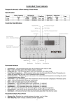
5. ELECTRONIC CONTROLLER INSTRUCTION
5-1. HOW TO USE THE TEMPERATURE CONTROL
5-2. FUNCTION TABLE
6. SPARE PARTS LIST
7. REPLACEMENT OF MAIN COMPONENTS
7-1. REPLACING THE EVAPORATOR COIL
7-2. ACCESSING CONDENSER COMPARTMENT
1
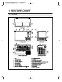
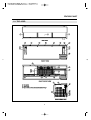
1. FEATURE CHART
1-1. TBC-50SD
2
FEATURE CHART
1-2. TBC-95SD
3
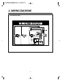
2. WIRING DIAGRAM
TBC-50SD/TBC-95SD
4
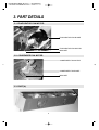
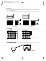
3. PART DETAILS
3-1. EVAPORATOR FAN MOTOR
EVAPORATOR FAN BLADE
EVAPORATOR FAN MOTOR
BRACKET
3-2. CONDENSER FAN MOTOR
CONDENSER FAN MOTOR
CONDENSER FAN BLADE
BRACKET
3-3. DUCT(A)
5
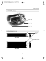
PART DETAILS
3-4. DUCT(B), (C), (D)
DUCT (D)
DUCT (B)
DUCT (C)
3-5. EVAPORATOR COIL
SENSOR
INLET
[TBC-50SD]
ACCUMULATOR
[TBC-95SD]
6
PART DETAILS
3-6. CONDENSER COIL
INLET
INLET
OUTLET
OUTLET
[TBC-50SD]
[TBC-95SD]
3-7. DIVIDER
20.76
10.91
5.91
20.76
Unit: inches
[TBC-50SD]
[TBC-95SD]
3-8. DIVIDER SPRING
Unit: inches
7
PART DETAILS
3-9. SHELF BOTTOM
Unit: inches
[TBC-50SD]
[TBC-95SD]
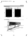
3-10. COUNTERTOP
LID RAIL LEFT
AIR GUIDE
COUNTERTOP
LID RAIL
MIDDLE
LID RAIL FRONT
LID RAIL RIGHT
COUNTERTOP FRAME ASSEMBLY
8
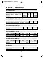
4. MAIN COMPONENTS
4-1. COMPRESSOR
MODEL
PART NAME
PART NO.
HORSE
POWER
TBC-50SD
CAE4440Y
30200B4200
1/3HP
TBC-95SD
CAE4456Y
30200B4500
1/2HP
CAPACITY
TYPE OF
MOTOR
INPUT
CSIR
-
CSIR
-
4,112BTU/h
(1,037Kcal/h)
5,592BTU/h
(1,410Kcal/h)
MAKER
TECUMSEH
EUROPE
TECUMSEH
EUROPE
4-2. COMPRESSOR RELAY, OVERLOAD
MODEL
RELAY
PART NO.
TBC-50SD MTRPH0033 Comp.Assembly
TBC-95SD 3ARR12KP*498 Comp.Assembly
OVERLOAD
MRT16AHKE
MST16AGZ
PART NO.
Comp.Assembly
Comp.Assembly
MAKER
–
–
NOTE
–
–
4-3. COMPRESSOR CAPACITOR
MODEL
TBC-50SD
TBC-95SD
STARTING
PART NO.
RUNNING
315µF/160V Comp. Assembly
–
315µF/160V Comp. Assembly
–
PART NO.
–
–
MAKER
–
–
NOTE
–
–
4-4. CONDENSER FAN MOTOR
MODEL
PART NAME
PART NO. POLE
TBC-50SD
TBC-95SD IS4420DWSG-1 3963220410
INPUT
4P
47W
BLADE
MAKER
(NUMBER)
Shaded Pole
AL
SUNGSHIN
Induction
4
TYPE
4-5. EVAPORATOR FAN MOTOR
MODEL
PART NAME
PART NO. POLE
TBC-50SD
TBC-95SD DAI-6152DEUA 3963339900
INPUT
2P
22.5W
BLADE
MAKER
(NUMBER)
Shaded Pole
NA-66
DAEYOUNG
Induction
4
TYPE
4-6. SWITCH
MODEL
PART NAME
TBC-50SD,95SD POWER SWITCH (ROCKER SWITCH)
TBC-50SD
THERMOSTAT
TBC-95SD
THERMOSTAT
9
PART NO.
RATING
30281Q0100
125V/15A
30283M0100 K55Q-5608, 16A
30283L0100 K55Q-5607, 16A
MAKER
SKT
RANCO
RANCO
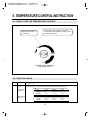
5. TEMPERATURE CONTROL INSTRUCTION
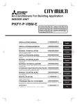
5-1. HOW TO USE THE TEMPERATURE CONTROL
- Temperature can be controlled by the user.
- Factory setting is at ‘NORMAL’. Settings can be
changed by Dial Knob.
- Indicates temperature
level setting.
COOL
OFF
NORMAL
COLD
TEMPERATURE CONTROL
(TBC-50SD, 95SD)
5-2. FUNCTION TABLE
No
1
Function
Temperature
Control
Controlled
Part
Description
1. The temperature can be changed by turning the dial knob.
Compressor
Cond. Fan Motor 2. Compressor is automatically turned on and off by thermostat.
■ Cut in and out temperature chart. ˚F (at evaporator coil)
Model: TBC-50SD
(K55Q-5608)
Model: TBC-95SD
(K55Q-5607)
No.
Cool
Normal
Cold
Cut in
Cut Out
40.1 ± 2.7
21.2
40.1 ± 2.7
17.1
40.1 ± 2.7
10.4
No.
Cool
Normal
Cold
Cut in
Cut Out
40.1 ± 2.7
23.9
40.1 ± 2.7
21.2
40.1 ± 2.7
17.6
10
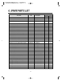
6. SPARE PARTS LIST
Part name
LID PARTS
LID
LID
LID HANDLE
COMPRESSOR COMPARTMENT
COMPRESSOR BASE
COMPRESSOR BASE
COMPRESSOR
COMPRESSOR
COMPRESSOR HARNESS ASSEMBLY
CONDENSER FAN MOTOR
CONDENSER FAN BLADE
CONDENSER FAN MOTOR BRACKET
CONDENSER COIL
CONDENSER COIL
COMPRESSOR PULL-OUT
COMPRESSOR PULL-OUT
CONNECTING PIPE(CONDENSER↔DRYER)
CONNECTING PIPE(CONDENSER↔DRYER)
COMPRESSOR DRYER
COMPRESSOR DRYER
CAPILLARY TUBE
CAPILLARY TUBE
SUCTION LINE
SUCTION LINE
POWER CORD
GRILLE ASSEMBLY
REFRIGERATION COMPARTMENT
EVAPORATOR COIL
EVAPORATOR COIL
DUCT(A)(INCLUDES FAN SHROUD)
DUCT(B)(LOUVERED)
DUCT(B)(LOUVERED)
DUCT(C)
DUCT(D)
EVAPORATOR DRAIN ELBOW
Code
Description
Model
50SD
95SD
30200B6100
30200B6110
30226B0100
EXCEPT LID HANDLE
EXCEPT LID HANDLE
ABS BLACK COLOR
2
30200B0900
30200B4100
30200B4200
30200B4500
30227B1500
3963220410
30218B0300
3020602200
30200B3500
30200B3600
30244B3200
30244B3300
30244B3400
30244B3410
30268L0300
30268L0400
30244B2910
30244B2920
30200B3700
30200B3800
30213A1012
30200B4400
SPG T2.0
SPG T2.0
CAE4440Y(115V/60Hz)
CAE4456Y(115V/60Hz)
1
IS-4420DWSG-1
AL ø200
SPG T2.0
CU, R8 * C4
CU, R8 * C8
CU, ODø6.35
CU, ODø6.35
CU, ODø7.94
CU, ODø7.94
XH-9, 50g, ø3.1
XH-9, 50g, ø3.5
IDø1.6 * L2375
IDø2.0 * L2375
CU, ODø7.94
CU, ODø9.52
KKP-30
STAINLESS STEEL
30270B0210
30270B0310
30200B4300
30269B0500
30269B0600
30220B1000
30220B1100
30225L0100
CU, R6 * C2
CU, R11 * C2
STAINLESS STEEL
STAINLESS STEEL
STAINLESS STEEL
STAINLESS STEEL
STAINLESS STEEL
NA-6
11
2
3
3
1
1
1
1
1
1
1
1
1
1
1
1
1
1
1
1
1
1
1
1
1
1
1
2
1
1
2
1
1
1
1
1
1
1
1
1
1
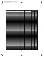
Part name
EVAPORATOR DRAIN ELBOW CAP
EVAPORATOR DRAIN HOSE
LEAK TEST COVER
LEAK TEST COVER
EVAPORATOR FAN MOTOR
EVAPORATOR FAN BLADE
EVAPORATOR FAN MOTOR BRACKET
EVAPORATOR FAN MOTOR HARNESS ASSEMBLY
TEMPERATURE CONTROL BOX
TEMPERATURE CONTROL BOX
TEMPERATURE CONTROL(THERMOSTAT)
TEMPERATURE CONTROL(THERMOSTAT)
POWER SWITCH
TEMPERATURE CONTROL KNOB
TEMPERATURE CONTROL HARNESS ASSEMBLY
COUNTERTOP PARTS
COUNTERTOP(URETHANE FOAM INSIDE)
COUNTERTOP(URETHANE FOAM INSIDE)
COUNTERTOP FRAME ASSEMBLY
COUNTERTOP FRAME ASSEMBLY
LID RAIL LEFT
LID RAIL RIGHT
LID RAIL FRONT
LID RAIL FRONT
LID RAIL MIDDLE
LID RAIL COVER("U" SHAPE)
AIR GUIDE
AIR GUIDE
MISCELLANEOUS
DIVIDER
DIVIDER
DIVIDER BUSH(CLIP)
DIVIDER SPRING
SHELF BOTTOM
SHELF BOTTOM
CAP CATCHER ASSEMBLY(WITH CAP OPENER)
CONDENSATE DRAIN PAN
Code
Description
30209L0200
30232A0200
30214B2900
30214B3000
3963339900
3011802400
30220T0300
30227B1100
30245B1600
30245B1610
30283M0100
30283L0100
30281Q0100
30234A1000
30227B1200
NA-6
PVC, L=140mm
STAINLESS STEEL
STAINLESS STEEL
DAI-6152DEUA
NA-66, ø110
STAINLESS STEEL
30200B5700
30200B5710
30222B1500
30222B1600
30287B0230
30287B0240
30287B0210
30287B0220
30287B0110
30225B0100
30225B0400
30225B0500
STAINLESS STEEL
STAINLESS STEEL
STAINLESS STEEL
STAINLESS STEEL
ABS BLACK COLOR
ABS BLACK COLOR
ABS BLACK COLOR
ABS BLACK COLOR
ABS BLACK COLOR
STAINLESS STEEL
STAINLESS STEEL
STAINLESS STEEL
30278B0600
30278B0700
30207B0100
30251B0200
30278B0800
30278B0900
30200B6400
30211B0100
PE COATING
PE COATING
NA-66, ø10
STAINLESS STEEL
PE COATING
PE COATING
EMBLEM INCLUDED
HIPS BLACK COLOR
12
STAINLESS STEEL
STAINLESS STEEL
K55Q-5608
K55Q-5607
125V/15A
HIPS WHITE COLOR
Model
50SD
95SD
1
1
1
1
1
1
2
2
2
2
4
4
1
1
1
1
1
1
1
1
1
1
1
1
1
1
1
1
1
1
1
4
1
1
1
1
1
2
6
1
3
54
3
2
1
1
6
144
6
5
2
1
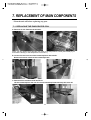
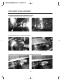
7. REPLACEMENT OF MAIN COMPONENTS
* Turn the unit off before replacing any part.
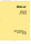
7-1. REPLACING THE EVAPORATOR COIL
A. Remove all lids. Remove the dividers.
(Now, you can replace the evaporator fan motor or the temperature control (thermostat) if you
unscrew the duct(A) or the temperature control box.)
B. Cut the silicone line around the countertop frame with a knife.
Remove all screws in back of the countertop frame.
C. Remove all the screws around the lid rail.
Lift the countertop from the rear first. Push countertop forward and top will come off.
13
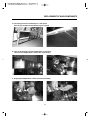
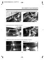
REPLACEMENT OF MAIN COMPONENTS
D. Carefully move the countertop to a safe place.
See the join bracket and understand join system.
E. This is the duct(A) and the temperature control box.
Unscrew the temperature control box if necessary.
F. Unplug the temperature control harness assembly.
14
REPLACEMENT OF MAIN COMPONENTS
G. Pull the sensing tube of the temperature control.
Replace the temperature control if necessary.
H. Remove the screws on duct(A) and remove.
I. Unplug the evaporator fan motor harness assembly if necessary.
15
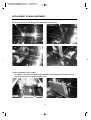
REPLACEMENT OF MAIN COMPONENTS
J. Remove screws to the evaporator fan motor if necessary and replace it with new one.
K. Remove the screws on duct(B) and remove.
L. Remove the screws on the suction line cover (horizontal) if necessary.
16
REPLACEMENT OF MAIN COMPONENTS
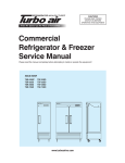
M. Remove screws to the duct(C) and the duct(D) if necessary.
N. Now evaporator coil is visible.
To replace it, cut out at the welding point between the accumulator and the suction
line, and also of the end of the capillary tube.
17
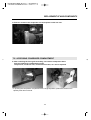
REPLACEMENT OF MAIN COMPONENTS
O. Remove screws to the evaporator coil and replace it with new one.
7-2. ACCESSING CONDENSER COMPARTMENT
A. After removing the front grille assembly, unscrew the compressor base.
Pull the compressor compartment slowly.
Compressor, condenser coil, condenser fan motor, etc. can be replaced.
• In pushing the compressor compartment to the original position, please be careful so the
capillary tube does not bend.
18