1
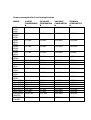
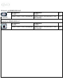
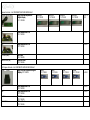
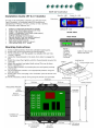
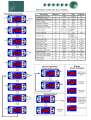
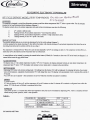
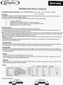
INSTALLATION & USER GUIDE
FOOD COOLING CABINETS
1. General
upon receipt of the refrigeration equipment, remove all external and internal packaging. Carefully inspect the unit for
evidence of transit damage or short shipment and inform the manufacturers or distribution company immediately in
writing, quoting machine serial number. Claims for faulty goods may not be subsequently considered if the above is
ignored.
If the unit is a replacement for an existing machine please remember that if it is the intention to scrap the redundant
item there is a legislative requirement to ensure that all cfc refrigerants are reclaimed and disposed of in a proper
manner. We would be pleased to offer advice on this.
2. SITING
Each unit is equipped with a complement of shelf supports, shelf slides and shelves as detailed in the product
specification. These items should be installed prior to use.
Ensure that the cabinet is sited on a level surface to enable correct drainage of condensate water from within the unit
and allow self closing mechanism on door assemblies to function. In the case of models fitted with castors, sited on
an uneven floor it may be necessary to fit adjustable legs to the equipment in order to make sure it is level. These
are available from the manufacture. Siting of the equipment is important if correct operation is to be achieved. Whilst
the equipment is designed to work in high ambient temperatures, adequate ventilation must be provided in order to
allow heat removal. Do not site refrigerators next to cooking equipment or within a continually bright sunlit position.
If the machine has laid flat during the installation process, allow to stand upright for a minimum period of 4 hours
before the equipment is switched on at the mains power supply. Machines supplied with castors incorporate a braking
mechanism. When the machine is sited in the chosen location apply the brake by activating the lever with your foot.
3. USER INSTRUCTIONS
Here are some general guides which will help to ensure trouble free operation of the equipment;
Do not:
put hot or steaming food into the equipment.
Do not:
overload the cabinet.
Do not:
block air flow ducts.
Do not:
leave cabinet doors open for longer than necessary.
Do not:
use sharp instruments for removing ice/food residue.
4. INSTALLATION
When the above factors have been completed the machine may be connected to a 13 amp 230 volt earthed socket,
which should be accessible for isolation of the equipment.
It is recommended that the equipment is protected by an RCCB installed to current IEE regulations. If in any doubt
consult a qualified electrician.
All products are subject to an electrical safety test (PAT) during manufacture. There is a test certificate fixed to the
rear of each machine. Upon switching on, a green indicator will illuminate in the control panel indicating power on.
The temperature display will also illuminate, it will indicate the internal air temperature of the cabinet. There is a built
in time delay of approximately 2 minutes before the compressor starts. When cooling action commences the display
will indicate a gradual fall in the internal temperature until the machines reaches the correct operating condition. The
machine should be allowed to cool to the specified temperature without door openings during this period. Only when
the machine is at the correct temperature, should food which is itself at, or close to the correct storage temperature,
be introduced into the unit.
5. USER MAINTENANCE
Switch off and unplug during maintenance operations. Do not perform cleaning operations with food/consumables in
the unit.
Do not attempt to remove any protective covers.
Warm soapy water is suitable cleaning solution for both internal and external finishes. Occasionally apply a
proprietary stainless polish to the external stainless steel surfaces.
Do not use abrasive cleaning materials or those containing bleach as these can effect the surface appearance of the
machine.
During cleaning operations check the condition of the door seal as it can be damaged through use and ineffective. If
signs of damage are evident , replace the seal by pulling it out of the retaining section in the door and simply push
replacement seal into place. Ensure grilles and condenser fins remain unobstructed and free from particles at all times.
A stiff brush or preferably a vacuum cleaner can be used. Remember to switch on machine after cleaning
operation is complete.
Power consumption for Food Cooling Products
MODEL
T450L
B450L
W16L
T450H
B450H
W16H
T600L
B600L
W21L
T600H
B600H
W21H
T900L
B900L
T900H
B900H
S140L
S140H
SS1L
WS1L
SS1H
WS1H
SS2L
WS2L
SS2H
WS2H
1D1L (WC1)
1D1H (WC1)
1D2L (WC1)
1D2H (WC1)
1D3L (WC1)
1D3H (WC1)
COLDROOM
FREEZER
COLDROOM
CHILLER
1 HOUR
CONSUMPSIO
N
0.55kWh
24 HOURS
CONSUMPSIO
N
4.4 kWh
364 DAYS
CONSUMPSIO
N
1602 kWh
STANDBY
CONSUMPTIO
N
0.031kWh
0.5 kWh
4.0 kWh
1446 kWh
0.031kWh
0.7 kWh
5.6 kWh
2038 kWh
0.031kWh
0.5 kWh
4.0 kWh
1446 kWh
0.031kWh
0.7 kWh
5.6 kWh
2038 kWh
0.058Wh
0.65 kWh
5.2kWh
1893 kWh
0.058kWh
0.5 kWh
0.3 kWh
0.45 kWh
4.0kWh
2.4 kWh
3.6 kWh
1446 kWh
874 kWh
1310 kWh
0.019kWh
0.019kWh
0.019kWh
0.285 kWh
2.28kWh
830 kWh
0.019kWh
0.5 kWh
4.0 kWh
1446 kWh
0.038kWh
0.35 kWh
2.8 kWh
1019 kWh
0.038kWh
0.5 kWh
0.36 kWh
0.55 kWh
0.36 kWh
0.55 kWh
0.5 kWh
0.690 kWh
4.0 kWh
2.88 kWh
4.4 kWh
2.88 kWh
4.4 kWh
4.0 kWh
5.52 kWh
1446
1048
1602
1048
1602
1446
2009
kWh
kWh
kWh
kWh
kWh
kWh
kWh
0.031kWh
0.031kWh
0.031kWh
0.031kWh
0.031kWh
0.031kWh
0.092kWh
0.745 kWh
11.64 kWh
4237 kWh
0.105kWh
6. INSTRUMENTATION AND DISPLAY
All our refrigeration units offer fully automatic operation and there is no requirement to adjust any of the controls.
Should the machine continually operate at a different temperature to that which is indicated on the control panel,
contact the manufacturer or service agent.
The machine will defrost at regular intervals. This is accompanied by a df readout.
The controller is a mains powered combined thermometer and thermostat and is microprocessor based (display is in
degrees C). As well as temperature readings the display will also exhibit various messages designed to inform the
user of the status of the machine or alarm messages as follows:
Df = cabinet is in defrost mode.
Df and temperature flashing = recovering from defrost.
Al and flashing temperature display = cabinet is in high temperature alarm.*
pF and flashing 40 = sensor probe failure.**
* Check all doors are closed. Wait 30 mins, if cabinet has not returned to the correct operating temperature
contact supplier. After the displayed temperature has returned to the normal AL message may still flash, this is
normal and the controller will reset at the next defrost period.
** Call supplier.
7. LOADING GUIDELINES
Ensure that the unit is large enough for your everyday storage requirements plus any extra load during peak periods
of activity. Do not be tempted to overload the units as this will only serve to reduce the air flow within the storage
area and thereby cause temperature stratification of the product within.
Where load line indicators are fitted ensure that food storage levels do not exceed the indicated mark.
Ideally raw and cooked foods should be kept in separate refrigerators. Where this is not possible always store cooked
food above raw food. Food should be covered or held in appropriate containers, preferably with clear lids in order to
avoid unnecessary handling in identification. Never put hot food into the refrigerator. This can cause severe rises in
the temperature of other products in the unit and cause condensation or ice build up.
Cooked foods can be left to cool for up to 1 ½ hours before refrigerating. If this is insufficient it may be necessary to
portion the product in order to accelerate the process.
8. SERVICE INFORMATION (Faults/repairs)
There are no user serviceable items inside the equipment.
Maintenance and repairs must only be carried out by a properly qualified and trained person.
In the event of a component failure, SWITCH OFF AND UNPLUG the unit.
Access to:-The compressor and electronic controller can be made via the unit compartment.
-The controller set up instructions are inside the electrical box.
9. SPARE PARTS IDENTIFICATION
Each machine is manufactured to an individual serial number by which date of manufacture, model type etc… can be
identified.
It is important that this serial number is included in any request for spares items.
The serial number may be found on a data plate, as shown below. It will be mounted on the left internal wall, above
the top shelf.
Name Of Unit
SERIAL No.
12345678
MODEL No.
24 1 ------
BAR CODE
REFRIGERANT
VOLTS
MAINS FUSE
QTY
CYCLES
WATTS
RETAIL CABINETS
IMI CORNELIUS UK LTD
RAWSON SPRING WAY
RIVERDALE INDUSTRIAL ESTATE
SHEFFIELD
S6 1PG
TEL… 0114 2852345
FAX… 0114 2320067
e-mail… [email protected]
RDM Controller Kit – ALL COMPONENTS SUPPLIED IN A KIT
High Temperature kit
37 0 7400070
Kit includes – Air probe 37 0 7400025,, PCB and Digital Display
RDM Digital Display
GP Controller Kit - ALL COMPONENTS SUPPLIED IN A KIT
GP Digital Display
High Temperature kit
37 0 7400052
Kit includes – Air probe 37 0 7400025,, PCB and Digital Display
Low temperature kit
37 0 7400071
Kit includes – Air probe 37 0 7400025, Defrost probe 37 0 7400026,
PCB and Digital Display
Low temperature kit
37 0 7400053
Kit includes – Air probe 37 0 7400025, Defrost probe 37 0 7400026,
PCB and Digital Display
Supply
Date
12/01 >
06/99 to
12/01
This is a GP style controller, it is held in
place by two clips at the rear.
This is the new RDM controller, it is held
in place with two screws at the rear.
This is the Pegasus style controller.
Display PCB is held in place by four pins
that are welded to the stainless steel
control panel.
The Display PCB is protected by a grey
adhesive membrane (label) which has a
window for the temperature display.
PART NUMBER AND
DESCRIPTION
191261-LT HONEYWELL/ELM GP LOW TEMP CONTROLLER
NOTES
PRE 2002
37 0 7400053
191260-HT HONEYWELL/ELM GP HIGH TEMP CONTROLLER
PRE2002
37 0 7400052
ELM
190937 HIGH TEMP PEGASUS CONTROLLER (PCB)
PRE 2002
37 0 7400028
ELM
190937 LOW TEMP PEGASUS CONTROLLER (PCB)
PRE 2002
37 0 7400029
ELM
BLACK BOX DISPLAY USED FOR PEGASUS
PRE 1994
37 0 7400024
ELM
190966 PEGASUS DISPLAY PRINTED CIRCUIT STRIP
PRE 2002
37 0 7400030
ELM
BLACK PROBE
37 0 7400025
ELM
RED PROBE
37 0 7400026
FROM
ELM
ELM
GREY TEMPERATURE PLAQUE -18/-22
(used with Pegasus display1994-2001)
GREY TEMPERATURE PLAQUE +1/+5
(used with Pegasus display 1994-2001)
GREY TEMPERATURE PLAQUE CHILL -2/0
(used with Pegasus display 1994-2001)
GREY TEMPERATURE PLAQUE MEAT +2/0
(used with Pegasus display 1994-2001)
OUR REF.
NUMBER
PRE2002
PRE 2002
37 0 7700030
PRE2002
PRE 2002
37 0 7700031
OLD BLUE PLAQUE -18/122
PRE 1994
37 0 7700103
OLD BLUE PLAQUE + 1/4
OLD BLUE PLAQUE BLANK
PRE 1994
PRE 1994
37 0 7700105
OLD BLUE PLAQUE CHILL +2 /0
PRE 1994
37 0 7700104
OLD BLUE PLAQUE MEAT -2/0
PRE 1994
37 0 7700101
RDM
DIN CONTROLLER LOW TEMP
NOW
37 0 7400071
RDM
DIN CONTROLLER HIGH TEMP
NOW
37 0 7400070
TP002KR DEFROST PROBE
NOW
37 0 7400026
TP002K AMBIENT PROBE
NOW
37 0 7400025
(NOTE THE PROBE'S ARE INTERCHANGEABLE WITH
EACH CONTROLLER AND HAVE THE SAME PART No.)
37 0 7700029
37 0 7700032
37 0 7700110
Pegasus Controller – ALL COMPONENTS SUPPLIED INDIVIDUALLY
Pegasus Digital Display
High and low temperature
digital display
37 0 7400030
membrane
37 0 7700030
membrane
37 0 7700029
membrane
37 0 7700031
membrane
37 0 7700032
04/94 to
12/01
PCB
Low temperature PCB
37 0 7400029
Pre 2002
PCB
High temperature PCB
37 0 7400028
Pre 2002
Air Probe (black)
Air Probe
37 0 7400025
Defrost Probe
37 0 7400026
Defrost Probe (red)
OLD Pegasus Controller - ALL COMPONENTS SUPPLIED INDIVIDUALLY
Digital
Display
High and low temperature digital
display 37 0 7400024
PCB
PCB
Air Probe
Defrost Probe
Low temperature PCB
37 0 7400029
High temperature PCB
37 0 7400028
Air Probe
37 0 7400025
Defrost Probe
37 0 7400026
Plaque
37 0 7700103
Plaque
37 0 7700101
Plaque
37 0 7700110
Plaque
37 0 7700104
Pre 1994
Pre 2002
Pre 2002
Parameter
GP or RDM Controller PARAMETERS
Display
Min.
Max.
Set-point
Temperature set-point
Operating parameters
Temp.differential
Probe offset
Set point maximum
Set point minimum
Comp. rest time
Defrost parameters
Defrost per day
Termination temp.
Termination time.
Defrost type: 0=Elect;1=Gas
Drain Down time
Fan Delay Time
Recovery time
Fan Delay term.temp.
Alarm parameters
Alarm duration
High temp.alarm offset
Low temp.alarm offset
Alarm delay
C1
Set-point Deg. .0C
Low
High
–50C/-20C +50C/+80C
-5
5
P1
P2
P3
P4
P5
0 Deg.0C
-10 Deg.0C
-63 Deg.0C
-63 Deg.0C
0 minutes
7 Deg.0C
7 Deg.0C
31 Deg.0C
31Deg.0C
20 minutes
3
0
-1
-6
2
3
0
9
4
2
D1
D2
D3
D4
D5
D6
D7
D8
0
0 Deg.0C
0 minutes
0
0 minutes
0 minutes
0 minutes
-20 Deg.0C
24
31 minutes
31 minutes
1
7 minutes
15 minutes
15 minutes
0 Deg.0C
4
15
20
0
1
5
10
-1
4
15
20
0
1
5
10
-1
A1
0 minutes
0= buzzer
61=buzzer
-63 Deg.0C
-63 Deg.0C
0 minutes
61 minutes
muted
continuous
0 Deg.0C
0 Deg.0C
60 minutes
15
15
10
10
30
10
10
30
A2
A3
A4
SET UP INSTRUCTIONS using a low temp board as a high
Parameter
Set-point
Temperature set-point
Operating parameters
Temp.differential
Probe offset
Set point maximum
Set point minimum
Comp. rest time
Defrost parameters
Defrost per day
Termination temp.
Termination time.
Defrost type: 0=Elect;1=Gas
Drain Down time
Fan Delay Time
Recovery time
Fan Delay term.temp.
Alarm parameters
Alarm duration
High temp.alarm offset
Low temp.alarm offset
Alarm delay
Display
C1
Min.
Set-point Deg.
Max.
.0C
Freezer
+1ºc/+4ºc
1
P1
P2
P3
P4
P5
0 Deg.0C
-10 Deg.0C
-63 Deg.0C
-63 Deg.0C
0 minutes
7 Deg.0C
7 Deg.0C
31 Deg.0C
31Deg.0C
20 minutes
3
0
5
1
2
D1
D2
D3
D4
D5
D6
D7
D8
0
0 Deg.0C
0 minutes
0
0 minutes
0 minutes
0 minutes
-20 Deg.0C
24
31 minutes
31 minutes
1
7 minutes
15 minutes
15 minutes
0 Deg.0C
4
15
15
0
2
0
10
-1
A1
0 minutes
0= buzzer
61=buzzer
-63 Deg.0C
-63 Deg.0C
0 minutes
61 minutes
muted
continuous
0 Deg.0C
0 Deg.0C
60 minutes
15
A2
A3
A4
10
10
30
1. Disconnect defrost solenoid and drip tray heater (on printed circuit board terminals 3).
2. Remove evap fan live from terminal 2 and put on to L terminal.
3. Disconnect door heater from L terminal.
Pegasus Break Down
ANALYSIS OF DISPLAY:
DISPLAY
DEFINITION
dF
Flashing between dF
& temperature
Flashing between Al &
temperature
Flashing between pF1
& temperature
POSSIBLE SOLUTION
System is in defrost
mode
System is recovering
from defrost mode
Cabinet temp is too
warm
Clean condenser &
check settings
Probe 1 is faulty, comp wil run
in 10 minute cycles.
Replace faulty probe
N/A
N/A
MANUAL DEFROST:
Manual defrost can be achieved by pressing & holding the defrost button on the temp
display for 6 seconds. Alternatively short out the 2 auxillary terminals on the PCB.
AUTOMATIC DEFROST:
The amount of defrosts per day is determined by dip switches 1 & 2 on the PCB. Dip
switch no.3 should always be in the 'OFF' position. Switch no. 4 selects hot gas defrost or
electric defrost.
OFF
ON=Electric defrost
ON
DIP SWITCHES
ON
1
2
3
OFF
Defrost Frequency
3 Per Day
4 Per Day
OFF=Hot gas defrost 6 Per Day
8 Per Day
4
Press 'SW2' X 4
Ch-1
Using flat blade screwdriver
adjust RV1 to set Ch1
Press 'SW2' X 1
Ch-2
Using flat blade screwdriver
adjust RV2 to set Ch2
Bit Switch
1
OFF
ON
OFF
ON
Bit Switch
2
OFF
OFF
ON
ON
Running temperature
setting.
COOLING SYSTEM SPECIFICATIONS FOR CORBY MANUFACTURED SILVERWING PRODUCTS
COUNTERS
W5H
W5L
W5M
Temp Range
Capillary
“C”
+1/+4
96” x 0.042”
-18/-22
117” x 0.042”
0/-2
96” x 0.042”
Condenser
Compressor
Gas
Charge
STFT14
STVF100
STFT14
BP1058Z
SC15BX
BP1058Z
R124a
R408a
R124a
180g
215g
180g
SL150H
SL150L
SL150M
+1/+4
-18/-22
0/-2
96” x 0.042”
117” x 0.042”
96” x 0.042”
STFT14
STVF100
STFT14
BP1058Z
SC15BX
BP1058Z
R124a
R408a
R124a
180g
215g
180g
S140H
S140L
S140M
S140H BOROGLASS
+1/+4
-18/-22
0/-2
+1/+4
96” x 0.042”
117” x 0.038”
96” x 0.042”
96” x 0.042”
STVF67
STVF100
STVF67
STVF67
BP1058Z
MP90FB
BP1058Z
THB4413Y
R124a
R404a
R124a
R124a
260g
270g
260g
260g
WS1 SS1H
WS1 SS1L
SS1 MC FLURRY
+1/+4
-18/-22
-18/-22
96” x 0.042”
117” x 0.038”
117” x 0.038”
STFT14
STVF100
STVF100
3.6CC
SC15BX
ML90FB
R124a
R408a
R404a
180g
215g
270g
WS2 SS2H
WS2 SS2L
+1/+4
-18/-22
96” x 0.042”
117” x 0.038”
STFT14
STVF100
AEZ4425Y
SC15BX
R134a
R408a
265g
215g
MD2
MD3
+1/+4
+1/+4
96” x 0.042”
96” x 0.042”
STVF100
STVF100
AEZ4430Y
CAE4440Y
R134a
R134a
370g
450g
1D1 1D2 1D3 H
1D1 1D2 1D3 M
1D1 1D2 1D3 L
1D2H PT
1D3H PT
1D4H
1D4M
1D4L
+1/+4
0/-2
-18/-22
+1/+4
+1/+4
+1/+4
+1/+4
-18/-22
96” x 0.042”
96” x 0.042”
117” x 0.038”
96” x 0.042”
96” x 0.042”
96” x 0.042”
96” x 0.042”
117” x 0.038”
STVF67
STVF67
STVF100
STVF100
STVF100
STVF100
STVF100
STVF100
AEZ4425Y
AEZ4425Y
SC15BX
AEZ4430Y
CAE4440Y
CAE4440Y
CAE4440Y
CAJ2428L
R134a
R134a
R408a
R134a
R134a
R134a
R134a
R408a
285g
285g
270g
370g
450g
425g
425g
355g
2D1H
2D1M
2D1L
2D2H
2D1M
2D1L
2D2H
2D1M
2D1L
2D1SP/SPB
2D2SP/SPB
2D3SP/SPB
+1/+4
0/-2
-18/-22
+1/+4
0/-2
-18/-22
+1/+4
0/-2
-18/-22
96” x 0.042”
96” x 0.042”
117” x 0.038”
96” x 0.042”
96” x 0.042”
117” x 0.038”
96” x 0.042”
96” x 0.042”
117” x 0.038”
STVF93
STVF93
STVF100
STVF100
STVF100
STVF100
STVF100
STVF100
STVF100
STVF93
STVF100
STVF194
AEZ4430Y
AEZ4430Y
SC15BX
AEZ4430Y
AEZ4430Y
SC15BX
CAE4440YY
CAE4440YY
CAJ2428L
Aez4430y
CAE4440Y
SC21G
R134a
R134a
R408a
R134a
R134a
R408a
R134a
R134a
R408a
R134a
R134a
R134a
330g
330g
270g
330g
330g
255g
425g
425g
355g
1000G
1000g
1000g
RT6
RT10 / RT12
5
5
144” X 0.038”
96” X 0.042”
STVF47
STVF67
THB1335Y
AEZ4425Y
R134a
R134a
150g
285g
COOLING SYSTEM SPECIFICATIONS FOR CORBY MANUFACTURED SILVERWING PRODUCTS
COUNTER TOP SPECS
Temp Range Capillary
“C”
S45H
+1/+4
4M X 0.031”
S45L
-18/-22
7M X 0.026”
Condenser
Compressor
Gas
Charge
STVF10
STVF10
B6132H
ML60FB
R134a
R134a
110g
200g
COOLING SYSTEM SPECIFICATIONS FOR CORBY MANUFACTURED SILVERWING PRODUCTS
TALL UPRIGHT CABINETS
Temp Range Capillary
Condenser
“C”
AMBASSADOR
+2/+6
3.3M X 0.052” STVF139
Compressor
Gas
Charge
SC15G
R134A
450g
W16 B450H
W16 B450M
W16 B450L
W16 B450HL
+1/+4
0/-2
-18/-22
+1/+4
-18/-22
96” X 0.042”
96” X 0.042”
117” X 0.042”
96” X 0.042”
117” X 0.042”
STVF93
STVF93
STVF100
STVF67
STVF67
AEZ4430Y
AEZ4430Y
SC15BX
AEZ4425Y
SC15BX
R134a
R134a
R408a
R134a
R408a
330g
330g
270g
285g
230g
W21 B600H
W21 B600M
W21 B600L
+1/+4
0/-2
-18/-22
-18/-22
96” X 0.042”
96” X 0.042”
117” X 0.042”
117” X 0.042”
STVF100
STVF100
STVF100
STVF139
AEZ4430Y
AEZ4430Y
SC15BX
MP14FB
R134a
R134a
R408a
R404a
370g
370g
340g
400g
B900H
B900M
B900l
+1/+4
0/-2
-18/-22
96” X 0.042” STVF100
96” X 0.042” STVF100
117” X 0.042” STVF100
CAE4440Y
CAE4440Y
SC15BX
R134a
R134a
R408a
425g
425g
335g
B1300H
B1300M
B1300L
+1/+4
0/-2
-18/-22
96” X 0.042” STVF100
96” X 0.042” STVF100
180” X 0.052” STVF194
CAE4440Y
CAE4440Y
SC21BX
R134a
R134a
R408
425g
425g
560g
T450H
T450M
T450L
+1/+4
0/-2
-18/-22
96” X 0.042” STVF93
96” X 0.042” STVF93
117” X 0.042” STVF100
AEZ4430Y
AEZ4430Y
SC15BX
R134a
R134a
R408a
330g
330g
270g
T600H
T600M
T600l
+1/+4
0/-2
-18/-22
-18/-22
96” X 0.042”
96” X 0.042”
117” X 0.042”
117” X 0.042”
STVF100
STVF100
STVF100
STVF139
AEZ4430Y
AEZ4430Y
SC15BX
MP14FB
R134a
R134a
R408a
R404a
370g
370g
340g
400g
T900H
T900M
T900l
+1/+4
0/-2
-18/-22
96” X 0.042” STVF100
96” X 0.042” STVF100
117” X 0.042” STVF100
CAE4440Y
CAE4440Y
SC15BX
R134a
R134a
R408a
425g
425g
335g
T1300H
T1300M
T1300L
+1/+4
0/-2
-18/-22
96” X 0.042” STVF100
96” X 0.042” STVF100
180” X 0.052” STVF194
CAE4440Y
CAE4440Y
SC21BX
R134a
R134a
R408
425g
425g
560g
G22H
G22M
G22L
G22HL
+1/+4
0/-2
-18/-22
+1/+4
-18/-22
96” X 0.042”
96” X 0.042”
102” X 0.042”
96” X 0.042”
117” X 0.042”
AEZ4430Y
AEZ4430Y
CAJ2428L
AEZ4425Y
SC15BX
R134a
R134a
R408a
R134a
R408a
370g
370g
330g
330g
270g
STVF100
STVF100
STVF100
STVF67
STVF67
G48H
G48M
G48L
+1/+4
0/-2
-18/-22
96” X 0.042” STVF100
96” X 0.042” STVF100
180” X 0.052” STVF194
CAE4440Y
CAE4440Y
CAJ2446L
R134a
R134a
R408a
425g
425g
520g
COOLING SYSTEM SPECIFICATIONS FOR CORBY MANUFACTURED SILVERWING PRODUCTS
ASDA PRODUCTS – CARTS ETC
Temp Range Capillary
“C”
AS0100
+1/+4
96” x 0.042”
AS0200
+1/+4
96” x 0.042””
AS0400
+1/+4
96” x 0.042”
AS0300
AS0500
+1/+4
+1/+4
0/+2
Condenser
Compressor
Gas
Charge
STVF100
STVF100
STVF100
ML80TFB
ML80TFB
ML80TFB
R404a
R404a
R404a
400g
400g
400g
96” x 0.042”
117” x 0.042”
96” x 0.042”
STFT14
STVF100
STFT14
BP1058Z
R404a
180g
BP1058Z
R404a
180g
AS0800
AS0900
0/-4
0/-4
NA
NA
STVF139
STVF139
MP12FB
MP90FB
R404a
R404a
1500g
1500g
Multideck 1000
+1/+4
NA
NA
CAJ4482YHR
R134a
1000g
IMI Cornelius
Rawson Spring Way
Riverdale Ind Est
Sheffield
S6 1PG
Tel. +44 (0) 1142 855886 Fax. +44 (0) 1142 321070