1
Service Manual
®
ROOM AIR CONDITIONER
Model: 79053/79056/79074/79122
79184/79188
• PREFACE
• DISASSEMBLY
INSTRUCTIONS
• INSTALLATION
• TROUBLESHOOTING
GUIDE
• CIRCUIT DIAGRAM
• EXPLODED
VIEW AND SERVICE PARTS LIST
CAUTION
- BEFORE
"SAFETY
SERVICING THE UNIT, READ THE
PRECAUTIONS"
IN THIS MANUAL.
- ONLY FOR AUTHORIZED
PERSONNEL.
SERVICE
Sears, Roebuck and Co., Hoffman
Estates, IL. 60179 U.S.A.
CONTENTS
1. PREFACE
...............................................................................................................................................
3
1.1 FEATURES
..................................................................................................................................................
1.2 SPECIFICATIONS
........................................................................................................................................
1.3 LOCATIONS OF CONTROLS
1.4 SAFETY PRECAUTIONS
......................................................................................................................
............................................................................................................................
1.5 INSULATION RESISTANCE TEST .....................................................................
2. DISASSEMBLY
INSTRUCTIONS
• MODELS: 79053/79056
".........................................
3
3
4
8
8
..............................................................................................
9
..................................................................................................................................
9
• MODEL: 79074 ..............................................................................................................................................
15
• MODEL: 79122 ..............................................................................................................................................
20
• MODELS: 79184/79188
25
................................................................................................................................
3. INSTALLATION ...........................................................................................................................
32
• MODELS: 79053/79056
................................................................................................................................
32
• MODELS: 79074/79122
................................................................................................................................
34
• MODELS: 79184/79188
................................................................................................................................
37
4. TROUBLESHOOTING
GUIDE ...................................................................................................
40
4.1 OUTSIDE DIMENSIONS ............................................................................................................................
40
4.2 PIPING SYSTEM
41
.......................................................................................................................................
4.3 TROUBLESHOOTING
5. CIRCUIT
GUIDE ...................................................................................................................
DIAGRAM
42
..........................................................................................................................
47
• MODEL: 79053 ..............................................................................................................................................
47
• MODEL: 79056 ..............................................................................................................................................
48
• MODEL: 79074 ..............................................................................................................................................
49
• MODEL: 79122 ..............................................................................................................................................
50
• MODEL: 79184 ..............................................................................................................................................
51
• MODEL: 79188 ..............................................................................................................................................
52
6. EXPLODED
VIEW AND SERVICE
PARTS LIST ...........................................................
53
• MODEL: 79053 ..............................................................................................................................................
53
• MODEL: 79056 ..............................................................................................................................................
56
• MODEL: 79074 .............. "...............................................................................................................................
59
• MODEL: 79122 ..............................................................................................................................................
62
• MODEL: 79184 ..............................................................................................................................................
65
• MODEL: 79188 ..............................................................................................................................................
68
--2--
1. PREFACE
This service manual provides various service information, including the mechanical and electrical parts, etc.
This room air conditioner was manufactured and assembled under a strict quality control system.
The refrigerant is charged at the factory. Be sure to read the safety precautions prior to servicing the unit.
1.1 FEATURES
•
•
•
•
•
•
DESIGNED FOR COOLING ONLY
POWERFUL AND INCREDIBLE COOLING
THE SIMPLE INSTALLATION AND SERVICE
BUILT-IN ADJUSTABLE THERMOSTAT
WASHABLE ONE-TOUCH FILTER
COMPACT SIZE
1.2 SPECIFICATIONS
__
ITEMS
MODELS
79053
79056
79074
79122
1(_, 115V, 60Hz
POWER SUPPLY
79184
79188
10, 208/-230V, 60Hz
5,100
5,400
7,000
12,000
17,500/18,000
INPUT(W)
565
540
760
1,260
1,940/ 2,000
RUNNING CURRENT(A)
5.2
4.8
7
11.5
9.6/9.0
9
10
9.2
9.5
26.6(DB) *
19.4(WB) *
COOLING CAPACITY
EER(Btu/hW)
OPERATION INDOOR('C)
CONDITION OUTDOOR('C)
35(DR) *
23.9(WB) *
7.8
11.1
12.4
17
26.1
EVAPORATOR
2R * 10C
2R * 10C
2R * 14C
2R * 13C
3R "15C
CONDENSER
1R * 14C
2R * 14C
2R * 16C
2R * 17C
2R "19C
REFRIGERANT(R-22) CHARGE
BLOWER
FAN, INDOOR
PROPELLER TYPE FAN WITH SLINGER-RING
FAN, OUTDOOR
FANSPEEDS, FAN/COOLING
OPERATIONCONTROL
ROOM TEMP CONTROL
2/2
R/St_T_
2/2
2/2
P,B/_)]E
cokr'_OL
RISWlTCH
2/3
_AT
VERTICAL LOUVER(RIGHT & LEFT)
HORIZONTAL LOUVER(UP & DOWN)
STRUCTURE
SUDE IN - OUT CHASSIS
TOP-DOWN
OVERLOAD PROTECTOR
PROTECTOR COMPRESSOR
FAN MOTOR
INTERNAL THERMAL PROTECTOR
3 WIRES WITH GROUNDING
POWER CORD
ATTACHMENT PLUG(CORD - CONNECTED TYPE)
DRAIN SYSTEM
* DB = DRY BULB TEMP.
DRAIN PIPE OR SLAPLSHED BY FAN SLINGER
* WB = WET BULB TEMP.
• NOTE: Specifications are subject to minor change without notice for further improvement.
--3--
2/2
R_'WlTCH REMOTECON]t_OL
R/SWITCH
THERMOSTAT11"IE_ISTOB _IEEV_3_rAT THE!_'TAT
AIR DIRECTION CONTROL
2/3
]HER_ISTOR
1.3 LOCATIONS
• MODEL:
OF CONTROLS
79053
• MODEL:
79074
s
OFF
HIGH
F-_--------_-._
i
HIGH
FANFF" -oooL
LOW /r
I
FAN'I
(
_
LOW
OFF
2• _
%
FAN
"gOOOL
,. ow
HIGH_
HIGH
I
FAN 3 _i
r COOL
!"cOOL
TEMP
MODE
MODE
• MODEL:
79122/79184
5
3•
4e
s
•6
OFF
•7
3•
•7
MED
_
FAN e///f
2
%
LOW•_\
HIGH
_'COOL
_
J_ /
FAN _
TEMP
I MED
COOL
LOW COOL
TEMP
MODE
TEMP
The thermostat will automatically control the temperature of the room. Select a higher number for lower room
temperature. The temperature is selected by turning the TEMP knob to the desired position.
The 5 or 6 position is a normal setting for average conditions.
MODE
OFF :
MED FAN :
LOW FAN :
HIGH COOL :
MED COOL :
LOW COOL :
Turns the air conditioner off.
Permits
Permits
Permits
Permits
Permits
the medium fan speed operation without cooling.
the low fan speed operation without cooling.
cooling with the high fan speed operation.
cooling with the medium fan speed operation.
cooling with the low fan speed operation.
• MODEL:
79056
DISPLAY
REMOCON SIGNAL RECEIVER
--
TEMPERATURE SETTING
y' Th s buttoncan automaticay contro the temperatureof the room.
The temperaturecan be set withina rangeof 60°F to 86°F by I°F.
Selectthe lowernumberfor lowertemperatureof the room.
The fan stopswhen the compressorstopscooling.
• Approximatelyevery3 minute_the fan willturnon and checkthe roomair to
determineifcoolingis needed.
--INERGY
SAVER
OOUFAN
O _._._
[ENERGY
_
SAVER
( T"T'_MER
L
ON/OFF_
_N
I :I_:F_e_M;R shthisbutt°n'
itwillt°gglebetween
COOL
andFAN"
OO_
O
I: STOPPING OPERATION
!
[
] ; STeArRtTImNGO:pEut_iONbutt°n,
when the set is n°t °perking , umeris set
- 12Hours--_Cancel)
as_lo°W__ HHUru"rs2H_JoHou3HlUlHo4H°urs
"5H°urs 6H°urs
-
• To turn the Set ON, push the button. To rum the Set OFF,
pushthe buttonagain.
• This buttontakes priorityover any otherbuttons.
_jN_rl'y_
_irsttum it _the Set is on the_gh coolmode
and the temp. _"
FAN SPEED
• Everytimeyou pushthis buttonit is set as follows.
(High -- Low-- High...)
--5--
7H°urs
REMOTE
CONTROL
Precaution: The Remote Controller will not operate propedy if strong light strikes the sensor window of the air
conditioner or if there are obstacles behveen the Remote Controller and the air conditioner.
ON/OFF TIMER
- STOPPING OPERATION
• Everytime you push this button, when the set is operating,
timer is set as follows.
(1Hour=.2Hours- 3Hours- 4Hours- 5Hours-- 6Hours
7Hours- 8Hours_-9Hours-10Hours_ 11Hours-- 12Hours_Cancel)
• The SettingTemperaturewillbe raised by 2°F 30rain. later
and by2°F afteranother 30 rain.
- STARTING OPERATION
• Even/timeyou pushthis button, when the set is
not operating, timer is set as follow.
(1Hour_2Hours-* 3Hours
_ 4Hours-_5Hours_ 6Hours7Hours- 8Hours_-9Hours_ 10Hours_ 11Hours-_12Hours- Cancel)
ENERGY SAVER
The fan stopswhen the compressorstopscooling.
• Approximatelyevely 3 minutesthe fan willtum on and
checkthe roomair to determineif coolingis needed.
COOL/FAN
• Eve_time you pushthis button,it willtogglebetween
COOL and FAN.
POWER
• To turnthe Set ON, pushthe button.To tum the Set OFF,
pushthe button again.
• Thisbuttontakes priorityover any otherbuttons,
• When you firstturn it on, the Set ison the High coolmode
and thetemp. at 72°F
TEMPERATURE SETTING
• This buttoncan automatically control the temperature
of the room.The temperature can be set withina rangeof
60°F to 86°F by I°F.
Selectthe lower number for lower temperature of the room.
FAN SPEED
• Everytimeyou push thisbuttonit is set as follows.
(High--,Low -_High...)
POWER
• MODEL:
79188
DISPLAY
-- ON/OFF TIMER
• Everyfimeyou pushthisbutton,timerisset as follows,
(1Hour-2Hours
- 3Hours
-*4Hours_5Hours-6Hours
7Hours_8Hours
-*9Hours
-*10Hours
-*11Hours
- 12Hours-Cancel)
• The SettingTemperaturewillbe raisedby2°F 30rain.later
and by2°F afteranother30 rain,
TIMER
• This buttoncan automatically
controltheairflowdirection.
I
UTO SWING
RECEIVER
AUTO
L
• To turnthe Set ON, pushthe
button.To tumthe Set OFF,
pushthe buttonagain.
• This buttontakespriorityover
anyotherbuttons.
• Whenyoufirsttumiton, the
Set ison the Highcoolmode
andthe temp.at 72°F
,-0
FAN SPEED
• Everytimeyoupushthisbutton, • EverylJme
you pushthis
it willtogglebetween
button,it isset as follows,
COOL and FAN.
(High_ Low- High...)
ENERGY SAVER
• The fan stopswhenthe compressor
stopscooling.
Approximately
every3 minutesthe fan willtumon and
checkthe roomair todetermineif coolingis needed.
m7m
TEMPERATURESETTING
• Thisbuttoncanautomatloaily
control
thetemperatureofthe room.
The temperaturecan be setwithine
rangeof60°Fto 86°Fby I°F.
Selectthe lowernumberfor lower
temperatureofthe room.
REMOTE
CONTROL
Precaution: The Remote Controller will not operate properly if strong light strikes the sensor window of the air
conditioner or if there are obstacles between the Remote Controller and the air conditioner,
AUTO SWING
• Presstheairflowdirectioncontrolbuttonforthe verticalIouver'sto swingautomatically,
ON/OFF TIMER
- STOPPINGOPERATION
• Ever/timeyoupush thisbutton,whenthe set isoperating,timeris set as follows.
(1Hour_2Hours
_ 3Hours
- 4Hours-5Hcers
_ 6Hours--_7Hours8Hours-9Hours
-*
10Hours-11Hours- 12Hours
-Cancel)
The SettingTemperaturewillbe raisedby 2°F 30rain.laterand by2°F after
another30 min.
- STARTINGOPERATION
• Everytimeyoupushthis button,whenthe set isnotoperating,timer isset
as follow. (1Hour-2Hours
- 3Hours-4Hours-5Hours-6Hours-_7Hours
8Hours
-, 9Hours
_ 10Hours
_ 11Hours--12Hours
-- Cancel)
POWER
ENERGY SAVER
The fanstopswhenthe compressor
stopscooling,
• Approximately
every3 minutesthe fanwillturnon and checkthe room
air to determineif coolingis needed.
FAN
SPEED
COOL/FAN
• Everytimeyoupushthis button,it willtogglebetween COOLand FAN.
POWER
• To turnthe Set ON, pushthe button.To tumthe Set OFF, pushthe buttonagain.
Thisbuttontakespriorityoveranyotherbuttons.
Whenyoufirstturniton, the Set is onthe Highcoolmodeandthe temp.at 72°F
TEMPERATURE SEI"rlNG
• This buttoncan automatically
controlthe temperatureofthe room.
The temperaturecan be set withina rangeof 60°Fto 86°F by I°F.
Selectthe lowernumberfor lowertemperatureofthe room.
FAN SPEED
• Everytimeyoupushthisbuttonit is setas follows.(High---Low---High..,)
1.4 SAFETY PRECAUTIONS
1.5 INSULATION
1. When servicing, set the ROTARY SWITCH to
Off ( O ) and unplug the power cord.
2. Observe the original lead dress.
If a short circuit is found, replace all parts which
1. Unplug the power cord and connect a jumper
between 2 pins (black and white).
2. The grounding conductor (green or green and yellow) is to be open.
3. Measure the resistance value with an ohm meter
have been overheated or damaged by the short
circuit.
RESISTANCE
TEST
between the jumpered lead and each exposed
metallic part on the equipment at all position
[except Off ( 0 )] of the ROTARY SWITCH.
4. The value should be over 1 M_.
3. After servicing, make an insulation resistance test
to prevent the customer from being exposed to
shock hazards.
---8--
2. DISASSEMBLY
INSTRUCTIONS
• MODEL: 79053/79056
2.1 MECHANICAL
2.1.1
FRONT
PARTS
GRILLE
1. Disconnect the unit from the power source.
2. Remove the two knobs by pulling them off.
Using a screwdriver, remove the screw that
secures the front grille to control board.
(See Figure 1)
3. Push the front grills up from the bottom.
Pull the top of the front grille away from the
cabinet as the top tabs lift out of their slots.
(See Figure 2)
4. Replace the grille by placing the tabs in the slots
and push the grille until it snaps into place.
Figure 1
Figure 2
2.1.2
CABINET
1. Disconnect the unit from the power source.
2. Remove the front grille. (Refer to Section 2.1.1)
3. Remove 6 screws that secure the cabinet to the
base pan. (See Figure 3)
4. Lift the cabinet from the unit.
5. Re-install by referring to the procedures above.
Figure
2.1.3
1.
2.
3,
4.
CONTROL
3
BOARD
Disconnect the unit from the power source.
Remove the front gdlle. (Refer to Section 2.1,1)
Remove the cabinet. (Refer to Section 2.1.2)
Remove 2 screws that secure the control board to
base pan and orifice, (See Figure 4)
5. Pull the control board toward yourself,
NOTE : Controls, wires, and capacitor are now
accessible for servicing. Discharge the
capacitor before servicing.
6. Disconnect one housing terminal and 3 wires for
the fan motor and compressor. (See Figure 5)
7. Re-install components by referring to procedures
above. (Refer to wiring diagram on pages 47-48
in this manual or inside control board.)
Figure 4
Figure 5
--9---
:_
2.2 AIR HANDLING
PARTS
2.2.1 ORIFICE
1. Disconnect the unit from the power source.
2. Remove the front gdlle. (Refer to Section 2.1.1)
3. Remove the cabinet. (Refer to Section 2.1.2)
4. Remove the control board.
(Refer to Section 2.1.3)
5. Remove 2 screws that secure the orifice.
(See Figure 6)
6. Uft orifice upward.
7. Re-install by referring to the procedures above.
Figure 6
2.2.2 BLOWER WHEEL, FAN AND SHROUD
1. Disconnect the unit from the power source.
2. Remove the front gdlle. (Refer to Section 2.1.1)
3. Remove the cabinet. (Refer to Section 2.1.2)
4. Remove the control board.
(Refer to Section 2.1.3)
5. Remove the orifice. (Refer to Section 2.2.1)
6. Remove the screw that secures shroud and air
Figure 7
guide. (Figure 7)
7. Remove 2 screws that secure the base pan.
(See Figure 8)
8. Remove the screw that secures the shroud to
channel of condenser.
9. Press the snap area of shroud with your thumbs.
This allows you to remove it from the condenser.
10. Lift the compressor upward with the evaporator
and condenser. (See Figure 8)
11. Remove the clamp springs which are clamped to
the boss of fan and blower wheel by hand plier.
(See Figure 9)
12. Pull the fan and blower wheel outward tilting it
foward yourself.
13. Remove the shroud.
Figure 8
14, Re-install by referring to the procedures above.
Figure 9
--10--
2.2.3 AIR GUIDE AND MOTOR
1. Disconnect the unit from the power source.
2. Remove the front grille. (Refer to Section 2.1.1)
3. Remove the cabinet. (Refer to Section 2.1.2)
4. Remove the control board.
(Refer to Section 2.1.3)
5. Remove the orifice. (Refer to Section 2.2.1 )
6. Remove the compressor, evaporator and
condenser. (Refer to Section 2.2.2)
7. Remove 2 screws that secure the motor to the air
guide. (See Figure 10)
8. Separate the motor by pulling it backward.
9. Remove 2 screws that secure the air guide to the
base fan. (See Figure 11)
10. Push the air guide backward and lift it upward.
(See Figure 11)
11. Re-install by referring to the procedures above.
Figure 10
Figure 11
2.3 ELECTRICAL
2.3.1 OVERLOAD
PARTS
PROTECTOR
1. Remove the cabinet. (Refer to Section 2.1,2)
2. Remove the nut which fastens the terminal cover.
3. Remove the terminal cover.
4. Remove all the leads from the overload protector.
5. Remove the ovedoad protector.
6. Re-install the components by referring to the
removal procedure above.
(See Figure 12 and 13)
Figure 12
--11--
Figure 13
2.3.2
COMPRESSOR
1. Remove the cabinet. (Refer to Section 2.1.2)
2. Discharge the refrigerant by using a refrigerant
recovery system,
3. Remove the overload protector.
(Refer to Section 2.3.1)
4. After discharging the unit completely, unbrace the
suction and discharge pipes at the compressor
connections.
5. Remove 3 nuts which fasten the compressor.
6. Remove the compressor.
7. Re-install by referring to the removal procedure
above, (See Figure 14)
2.3.3
CAPACITOR
1. Remove the cabinet. (Refer to Section 2.1.2)
2. Remove the control board.
Figure 14
(Refer to Section 2.1.3)
3. Discharge the capacitor by placing a 20 K.Q
resistor across the capacitor terminals.
4. Remove the screw which fastens the capacitor
clamp. (See Figure 15)
5. Remove all the leads of capacitor terminals.
6. Remove the capacitor
7. Re-install the components by referring to the
removal procedure above.
2.3.4
THERMOSTAT
1. Remove the cabinet. (Refer to Section 2.1.2)
2. Remove the control board.
Figure 15
(Refer to Section 2.1.3)
3. Remove 2 screws which fasten the thermostat.
(See Figure 16)
4. Remove all the leads of the thermostat terminals.
5, Remove the thermostat.
6. Re-install the components by referring to the
removal procedure above.
2.3.5 ROTARY SWITCH
Figure 16
1. Remove the cabinet, (Refer to Section 2,1.2)
2. Remove the control board.
(Refer to Section 2.1.3)
3. Remove 2 screws which fasten the rotary switch.
(See Figure 17)
4. Remove all the leads of the rotary switch
terminals.
_-_ Remove the rotary switch.
_!nstaU
the components by referring to the
R_;_val procedure above.
Figure 17
--12 D
2.3.6 FAN MOTOR
1.
2.
3.
4.
Disconnect the unit from the power source.
Remove the front grille. (Refer to Section 2.1.1 )
Remove the cabinet. (Refer to Section 2.1.2)
Remove the control board.
(Refer to Section 2.1.3)
5. Remove the orifice. (Refer to Section 2.2.1)
6. Remove the compressor, evaporator, and
condenser. (Refer to Section 2.2.2)
7. Remove the fan and blower wheel.
(Refer to section 2.2.2)
8. Remove the motor. (Refer to Section 2.2.3)
9. Remove the air guide. (Refer to Section 2.2.3)
10. Re-install by referring to procedures above.
Figure 18
2.3.7 POWER
CORD
1. Disconnect the unit from the power source.
2. Remove the front grille. (Refer to Section 2.1.1 )
3. Remove the cabinet. (Refer to Section 2.1.2)
4. Remove 2 screws that secure control board to
base pan and orifice (Refer to Section 2.1.3).
5. Pulls the control board toward you.
6. Disconnect the 2 receptacles and remove the
grounding screw.
7. Remove a screw secudng the clip with cord to the
control board. (See Figure 19)
8. Pull the power cord.
9. Re-install by referring to procedures above.
2.4 REFRIGERANT
Figure 19
CYCLE
2.4.1 CONDENSER
1. Remove the cabinet. (Refer to Section 2.1.2)
2. Discharge the refdgerant by using a refdgerant
recovery system.
3. Remove 2 screws which fasten the condenser.
(See Figure 20)
4. After discharging the refrigerant completely,
unbraze the interconnecting tube at the
condenser connections.
5. Remove the condenser.
6. Re-install by referring to the procedures above.
Rgure 20
--13--
2.4.2
EVAPORATOR
1. Remove the cabinet. (Refer to Section 2.1.2)
2. Discharge the refrigerant by using a refrigerant recovery system.
3. Remove the orifice. (Refer to Section 2.2.1)
4. After discharging the refrigerant completely, unbraze the interconnecting tube at the evaporator
connections,
5. Remove the evaporator.
6, Re-install by referring to the procedures above,
2.4.3 CAPILLARY
TUBE
1. Remove the cabinet. (Refer to Section 2.1.2)
2. Discharge the refrigerant by using a refrigerant recovery system.
3. Remove the orifice. (Refer to Section 2.2.1 )
4. After discharging the refrigerant completely, unbraze the interconnecting tube of the capillary tube.
5. Remove the capillary tube.
6. Re-install by referring to the procedures above.
--14--
• Model: 79074
-- Before the following disassembly, POWER SWITCH is set to OFF and disconnect the power cord.
2.5 MECHANICAL
2.5.1 FRONT
PARTS
GRILLE
1. Open the Inlet grille downward and remove the air
filter.
2.
3.
4.
5.
Remove the screw which fastens the front grille.
Pull the front grille from the right side.
Remove the front grille.
Re-install the component by referring to the
removal procedure, above. (See Figure 21)
Figure 21
2.5.2 CABINET
1. After disassembling the front gdile, remove the
screws which fasten the cabinet at both sides.
2. Remove the two screws which fasten the cabinet
at back.
3. Pull the base pan forward. (See Figure 22)
Figure22
2.5.3 CONTROL
BOX
1. Remove the front grille. (Refer to section 2,5.1)
2. Romove the 3 screws which fasten the control
box.
3. Pull the control box forward about 10-15cm.
4, Discharge the capacitor by placing a 20,000 ohm
resistor across the capacitor terminals,
5. Remove three wire housings in the control box.
6. Pull the control box forward completely.
7, Re-install the components by referring to the
removal procedure, above. (See Figure 23)
(Refer to the circuit diagram found on page 49
and 21 in this manual and on the control box.)
Figure 23
--15_
2.6 AIR HANDLING
PARTS
2.6.1 AIR GUIDE
1. Remove the front grille. (Refer to section 2.5.1)
2. Remove the cabinet. (Refer to section 2.5.2)
3. Pull the cover E.P.S upward.
4. Remove 3 screws which fasten the UPPER AIR
GUIDE
5. Push the two hooks which fasten the UPPER AIR
GUIDE and remove the UPPER AIR GUIDE.
6. Re-install the components by referring to the
above removal procedure.
Figure 24
Figure 25
2.6.2 BLOWER
1. Remove the air guide. (Refer to section 2.6.1)
2. Move the evaporator sideward carefully.
3. Remove the clamp which secures the blower with
a hand plier, (See Figure 26)
4. Remove 2 screws which fashen the motor mount.
5. Pull the blower forward by dragging the motor
mount upward carefully.
6. Remove the blower.
Figure 26
7. Re-install the components by referring to the
removal procedure, above.
Figure 27
--16---
2.6.3 FAN, SHROUD
1. Remove the cabinet. (Refer to section 2.5.2)
2. Remove the 4 screws which fasten the condenser,
3. Move the condenser sideward carefully.
4. Remove the clamp which secures the FAN with a
hand plier.
5. Remove the FAN,
6. Remove the SHROUD.
7. Re-install by referring to the removal procedure.
Figure 28
2.7 ELECTRICAL
2.7.1 OVERLOAD
PARTS
PROTECTOR
1. Remove the cabinet. (Refer to section 2.5.2)
2. Remove the nut which fastens the terminal cover.
3. Remove the terminal cover.
4. Remove all the leads from the overload protector.
5. Remove the overload protecto_
6. Re-install the component by referring to the above
removal procedure.
Figure 29
2.7.2 COMPRESSOR
1. Remove the cabinet. (Refer to section 2.5.2)
2. Discharge the regdgerant system using a
Freon TM Recovery System.
If there is no valvo to attach the recovery system,
install one (such as a watco a-l) before venting
the FreonTM Leave the valve in place after
servicing the system.
3. Remove the ovedoad protector. (Refer to section
2.7.1)
4. After purging the unit completely, detach the suc-
Figure 30
tion and discharge tube at the compressor connections.
5. Remove the 3 nuts and the 3 bracket washers
which fasten the compressor.
6. Remove the compressor.
7. Re-install the components by referring to the
removal procedure, above.
Figure 32
m17--
Figure 31
2.7.3
CAPACITOR
1. Remove the control box. (Refer to section 2.5.3)
2. Remove the screw and the clamp which fastens
the capacitor.
3. Disconnect all the leads of capacitor terminals.
4. Re-instan the components by referring to the
removal procedure, above.
2.7.4 POWER
CORD
1. Remove the control box. (Refer to section 2.5.3)
2. Disconnect the grounding screw from the control
box.(See Figure 34)
3. Disconnect 2 receptacles.
4. Remove a screw which fastens the clip cord.
5. Pull the power cord. (See Figure 35)
6. Re-install the component by referring to the above
removed procedure.
(Use only one ground-maked hole (_ for ground
connection.)
Figure 33
7. If the supply cord of this appliance is damaged, it
must be replaced by the special cord. (The
special cord means the cord which has the same
specification marked on the supply cord attached
at the unit.)
Figure 34
2.7.5 THERMOSTAT
1. Remove the control box. (Refer to section 2.5.3)
2. Remove the screw which fasten the display panel.
3. Remove the two knobs.
4. Remove the display panel.
5. Remove the 2 screws which fasten the thermostat.
6. Disconnect all the leads of thermostat terminals.
7. Remove the thermostat.
8. Re-install the components by referring to the
above removal procedure.
2.7.6 ROTARY SWITCH
1. Remove the controlbox. (Refer to section2.5.3)
2. Remove the screw which fastens the display panel.
3. Remove the two knobs.
Figure 36
4. Remove the display panel.
5. Remove 2 screws which fasten the rotaryswitch.
6. Disconnect all the leads of the rotaryswith
terminals.
7. Remove the rotaW switch.
8. Re-install the componentsby referring to the above
removal procedure.
Figure 37
m18--
Figure 35
2.7.7 MOTOR
1. Remove the cabinet. (Refer to section 2.5.2)
2. Remove the air guide. (Refer to section 2.6.1)
3. Remove the blower, (Refer to section 2.6.2)
4. Remove the fan. (Refer to section 2.6.3)
5, Remove the shroud. (Refer to section 2.6.3)
6, Remove the control box. (Refer to section 2.5.3)
7, Remove the 2 screws which fasten the motor.
8. Remove the motor.
9. Re-install the components by referring to the
above removal procedure,
2.8 REFRIGERATION
CYCLE
2.8.1 CONDENSER
1. Remove the cabinet. (Refer to section 2.5.2)
2. Discharge the refrigerant system using a Freon_
Recovery System.
If there is no valve to attach the recovery system,
install one (such as a WATCO A-l) before venting
the Freon TM. Leave the valve in place after servicing the system.
3. Remove the 4 screws which fasten the condenser.
4. After discharging the refrigerant completely,
detach the interconnecting tube at the condenser
connections.
5. Remove the condenser.
6. Re-install the component by referring to notes.
Figure 38
2.8.2 EVAPORATOR
1. Remove the cabinet. (Refer to section 2.5.2)
2. Discharge the refrigerant system using a FreonTM
Recovery System.
If there is no valve to attach the recovery system,
install one (such as a WATCO A-l) before venting
the FreonTM. Leave the valve in place after servicing the system.
3. Remove the cover E,P.S and the upper air guide
(Refer to section 2.6.1)
4. After discharging the refrigerant completely,
detach the interconnecting tube at the evaporator
connections.
5. Remove the evaporator.
6. Re-install the component by referring to notes.
2.8.3 CAPILLARY
Figure 39
TUBE
1. Remove the cabinet. (Refer to section 2.5.2)
2. Remove the upper air guide. (Refer to section
2.6.1)
3. Discharge the refrigerant system using a Freon_
Recovery System.
If there is no valve to attach the recovery system,
install one (such as a WATCO A-l) before venting
the Freon TM. Leave the valve in place after servicing the system.
4. After discharging the refrigerant completely,
detach the interconnecting tube at the CAPILLARY TUBE.
5. Remove the CAPILLARY TUBE.
6. Re-install the component by referring to notes.
Figure 40
m19--
• MODEL:
79122
-- Before the following disassembly, POWER SWITCH is set to OFF and disconnect the power cord.
2.9 MECHANICAL
PARTS
2.9,1 FRONT GRILLE
1.
2.
3.
4.
5.
Type A Screw
Open the inlet gdlle downward. (See Figure 41)
Remove the screw which fastens the front gdlle.
Pull the front gdlle from the right side.
Remove the front gdlle.
Re-install the component by referring to the
removal procedure, above.
Figure 41
2.9.2 CABINET
1. After disassembling the front gdlle, remove the 2
screws which fasten the cabinet at both sides.
2. Remove the 2 screws which fasten the cabinet at
back.
3. Pull the base pan forward. (See Figure 42)
4. Remove the cabinet.
5. Re-install the component by referring to the
removal procedure, above.
Figure 42
2.9.3 CONTROL
BOX
1. Remove the front gdlle. (Refer to section 2.9.1 )
2. Remove the cabinet. (Refer to section 2.9.2)
3. Remove the 2 screws which fasten the control
box cover.
4. Remove two housings which connect compressor
wire and motor wire in the control box.
5.Discharge the capacitor by placing a 20,000 ohmresistor across the capacitor terminals.
6. Remove the 2 screws which fasten the control
box.
7. Pull the control box forward completely.
8. Re-install the components by referring to the
removal procedure, above. (See Figure 43)
(Refer to the circuit diagram found on page 50 in
this manual and on the control box.)
Rgure 43
--20--
2.10 AIR HANDLING
PARTS
2.10.1 AIR GUIDE AND BLOWER
1,
2.
3.
4.
5.
6.
Remove
Remove
Remove
Remove
Remove
Remove
tor.
the front grille. (Refer to section 2.9.1)
the cabinet, (Refer to section 2.9.2)
the control box. (Refer to section 2.9,3)
the 4 screws which fasten the brace,
the brace.
the 2 screws which fasten the evapora-
7. Move the evaporator high side forward and pulling
it upside slightly. (See Figure 44)
8. Move the evaporator sideways carefully.
9. Pull out upside hook of orifice by pushing the tabs
and remove it. (See Figure 45)
10. Remove the clamp with hand plier which secures
the blower.
11. Remove the blower.
Figure 44
12. Remove the 4 screws which fasten the air guide
from the barrier.
13. Move the air guide backward and pulling out
from the base pan
14. Re-install the components by referdng to the
/
removal procedure, above.
Figure 45
2.10.2
FAN
1. Remove the cabinet. (Refer to section 2.9.2)
2. Remove the brace (Refer to section 2.10.1)
3. Remove the 4 screws which fasten the condenser.
4.
5.
6,
7.
Move the condenser sideways carefully.
Remove the clamp which secures the fan.
Remove the fan. (See Figure 46)
Re-install by referdng to the removal procedure.
Figure 46
--21--
2.10.3 SHROUD
1. Remove the fan. (Refer to section 2.10.2)
2. Remove the screw which fastens the shroud.
3. Remove the shroud. (See Figure 47)
4. Re-install the component by referring to the
removal procedure, above.
Figure 47
2.11 ELECTRICAL
2.11.1 OVERLOAD
PARTS
PROTECTOR
1. Remove the cabinet. (Refer to section 2.9.2)
2. Remove the nut which fastens the terminal cover.
3. Remove the terminal cover. (See Figure 48)
4. Remove all the leads from the ovedoad protector.
5. Remove the overload protector.
6. Re-install the component by referring to the
removal procedure, above.
Figure 48
2.11.2 COMPRESSOR
1. Remove the cabinet. (Refer to section 2.9.2)
2. Discharge the refrigerant system using a Freon_
Recovery System.
If there is no valve to attach the recovery system,
install one (such as a watco a-l) before venting
the FreonTM. Leave the valve in place after
servicing the system.
3. Remove the overload protector. (Refer to section
2.11.1)
4. After purging the unit completely, unbraze the suction and discharge tubes at the compressor connections.
5. Remove the 3 nuts and the 3 washers which
fasten the compressor.
6. Remove the compressor. (See Figure 49)
7. Re-install the components by referring to the
removal procedure, above.
--22D
Figure 49
2.11.3
CAPACITOR
1. Remove the control box. (Refer to section 2.9,3)
2. Remove the screw which located in the front,
3. Open the bottom side of control box.
4. Remove the screw and the clamp which fastens
the capacitor.
5. Disconnect all the leads of capacitor terminals.
6. Re-instal! the components by referring to the
removal procedure, above. (See Figure 50)
2.11.4 POWER
CORD
1. Remove the control box. (Refer to section 2.9.3)
2. Open the control box. (Refer to section 2.9.3)
3. Disconnect the grounding screw from the control
box.
Figure 50
4. Disconnect the 2 receptacles.
5. Remove a screw which fastens the clip cord.
(See Figure 51)
6. Remove the power cord.
7. Re-install the component by referring to the above
removed procedure, above.
(Use only one ground-marked hole (_ for ground
connection.)
8. If the supply cord is damaged, it must be replaced
by a special cord or assembly available from the
manufacturer or its service agent.
Figure 51
2.11.5 THERMOSTAT
1. Remove the control box. (Refer to section 2.9.3)
2. Open the control box. (Refer to section 2.9.3)
3. Remove the 2 screws which fasten the thermostat.
4. Disconnect 2 leads of thermostat terminals.
5. Remove the thermostat.
6. Re-install the components by refereing to the
above removal procedure.
2.11.6 ROTARY SWITCH
Figure 52
1. Remove the control box. (Refer to section 2.9.3)
2. Open the control box. (Refer to section 2.9.3)
3. Remove the 2 screws which fasten the rotary
switch.
4. Disconnect all the leads of the rotary switch terminals.
5. Remove the rotary switch.
6. Re-install the components by referring to the
above removal procedure.
Figure 53
--23--
2.11.7 MOTOR
1.
2.
3,
4.
5.
6.
Remove the cabinet. (Refer to section 2.9.2)
Remove the evaporator.
Remove the orifice. (Refer to section 2.10,1 )
Remove the blower. (Refer to section 2.10.1)
Remove the fan. (Refer to section 2.10.2)
Remove the control box cover and disconnect 5 or
4 wires of motor housing. (Refer to section 2,9.3)
7. Remove the 4 screws which fasten the motor from
the mount motor. (See Figure 54.)
8. Remove the motor.
9. Re-install the components by referring to the
removal procedure, above.
2.12 REFRIGERATING
Figure 54
CYCLE
Discharge the refrigerant system using a
Freon TM Recovery System.
If there is no valve to attach the recovery
system, install one (such as a WATCO A-l)
before venting the Freon TM. Leave the valve in
place after servicing the system.
2.12.1 CONDENSER
1. Remove the cabinet• (Refer to section 2.9.2)
2. Remove the 4 screws which fasten the
• brace.(Refer to section 2.10.1)
3. Remove the 5 screws which fasten the condenser
and shroud.
4. After discharging the refrigerant completely,
unbraze the interconnecting tube at the condenser
connections.
5. Remove the condenser.
6. Re-install the component by referring to notes•
Figure 55
2.12.2 EVAPORATOR
1. Remove the cabinet. (Refer to section 2.9.2)
2. Remove the 2 screws which fasten the evaporator.
3. Move the evaporator sideways carefully.
(Refer to section 2.10.1)
4. After discharging the refrigerant completely,
unbraze the interconnecting tube at the evaporator connections.
5. Remove the evaporator.
6. Re-install the component by referring to notes.
2.12.3 CAPILLARY
TUBE
1. Remove the cabinet. (Refer to section 2.9.2)
2. After discharging the refrigerant completely,
unbraze the interconnecting tube at the capillary
tube.(See caution above)
3. Remove the capillary tube.
4. Re-install the component by referdng to notes.
Figure 56
---24---
• MODEL: 79184/79188
-- Before the following disassembly, POWER SWITCH is set to OFF and disconnected the power cord.
2.13 MECHANICAL
2.13.1 FRONT
PARTS
GRILLE
1. Open the inlet grille downward.
2. Remove the screw which fastens the front grille.
3. Pull the front gdlle from the dght side.
4. Remove the front gdlle. (See Figure 57)
5. Re-install the component by referring to the
removal procedure.
Figure 57
2.13.2 CABINET
1. After disassembling the front gdlle, remove the
screws which fasten the cabinet at both sides.
2. Remove the two screws which fasten the cabinet
at back. (See Figure 58)
3. Pull the base pan forward.
Figure 58
2.13.3 CONTROL
BOX
1. Remove the front gdlle. (Refer to section 2.13.1 )
2. Pull the base pan forward so that you can remove
the 2 screws which fasten the cover control at the
dght side. (See Figure 59)
3. Remove the 3 screws which fasten the control
box. (See Figure 59, only for 79188)
4. Discharge the capacitor by placing a 20,000 ohm
resistor across the capacitor terminals.
5. Disconnect two wire housings in the control box.
6. Pull the control box forward completely.
7. Re-install the components by referring to the
removal procedure.
(Refer to the circuit diagram found on pages
51_52 in this manual and on the control box.)
Figure 59
--25---
2.14 AIR HANDLING
PARTS
2.14.1 COVER (AT THE TOP)
1. Remove the front grille. (Refer to section 2.13.1)
2. Remove the cabinet. (Refer to section 2.13.2)
3. Remove 11 screws which fasten the brace and
covers.
4. Remove the covers and the brace.
(See Figure 60)
5. Re-install the components by referring to the
removal procedure, above.
Figure 60
2.14.2 BLOWER
1. Remove the cover. (Refer to section 2.14.1)
2. Remove the 3 screws which fasten the evaporator
at the left side and the top side.
3. Move the evaporator sideward carefully.
4. Remove the orifice from the air guide carefully.
5. Remove the clamp which secures the blower with
plier. (See Figure 61)
6. Remove the blower with plier or your hand without
Figure 61
touching blades. (See Figure 62)
7. Re-instaU the components by referring to the
removal procedure, above.
Figure 62
2.14.3 FAN
1. Remove the cabinet. (Refer to section 2.13.2)
2. Remove the brace and shroud cover.
(Refer to section 2.14.1)
3. Remove the 5 screws which fasten the condenser.
4.
5.
6.
7.
Move the condenser sideways carefully.
Remove the clamp which secures the fan.
Remove the fan. (See Figure 63)
Re-install the components by referring to the
removal procedure, above.
Figure 63
---26--
2.14.4
SHROUD
1. Remove the fan. (Refer to section 2.14.3)
2. Remove the 2 screws which fasten the shroud.
3. Remove the shroud. (See Figure 64)
4. Re-install the component by referring to the
removal procedure, above.
Figure 64
2.15 ELECTRICAL
PARTS
2.15.1 MOTOR
1. Remove the cabinet. (Refer to section 2.13.2)
2. Remove the cover control and disconnect a wire
housing in control box. (Refer to section 2.13.3)
3. Remove the blower. (Refer to section 2.14.2)
4. Remove the fan. (Refer to section 2.14.3)
5. Remove the 4 screws which fasten the motor.
(See Figure 65)
6. Remove the motor.
7. Re-install the components by referring to the
removal procedure, above.
Figure 65
2.15.2
COMPRESSOR
1. Remove the cabinet. (Refer to section 2.13.2)
2. Discharge the refrigerant system using FreonTM
Recovery System.
If there is no valve to attach the recovery system,
install one (such as a watco a-1 ) before venting
the FreonTM. Leave the valve in place after
servicing the system.
3. Disconnect the 3 leads from the compressor.
4. After purging the unit completely, unbrace the suction and discharge tubes at the compressor connections.
5. Remove the 3 nuts and the 3 washers which fasten the compressor.
Figure 66
6. Remove the compressor. (See Figure 66)
7. Re-instill the components by referring to the
removal procedure, above.
--27--
2.15.3 CAPACITOR
1. Remove the control box. (Refer to section 2.13.3)
2. Remove the screw and knobs which fasten the
display panel.
3, Disconnect the 2 leads from the rocker switch and
remove the panel.
4. Remove a screw and unfold the control box.
(See Figure 67)
5. Remove the screw and the clamp which fastens
the capacitor.
6. Disconnect all the leads of capacitor terminals.
7. Re-install the components by referring to the
removal procedure, above.
Figure 67
2.15.4 POWER
CORD
1. Remove the control box. (Refer to section 2.13.3)
2. Unfold the control box. (Refer to section 2.15.3)
3. Disconnect the grounding screw from the control
box.
4.
5.
6.
7.
Disconnect 2 receptacles.
Remove a screw which fastens the clip cord.
Pull the power cord. (See Figure 68)
Re-install the component by referring to the
removal procedure, above.
(Use only one ground-marked hole O for ground
connection.)
8. If the supply cord of this appliance is damaged, it
must be replaced by the special cord.
(The special cord means the cord which has the
same specification marked on the supply cord fitted to the unit.)
Figure 68
2.15.5 THERMOSTAT
1.
2.
3.
4.
Remove the control box. (Refer to section 2.13.3)
Unfold the control box. (Refer to section 2.15.3)
Remove the 2 screws whichfasten the thermostat.
Disconnect all the leads of thermostat terminals.
5. Remove the thermostat. (See Figure 69)
6. Re-install the components by referring to the
removal procedure, above.
Figure 69
--28---
2.1 5.6 ROTARY
1.
2.
3.
4.
SWITCH
Remove the control box. (Refer to section 2.13.3)
Unfold the control box. (Refer to section 2.15.3)
Remove 2 screws which fasten the rotary switch.
Disconnect all the leads of the rotary switch terminals.
5. Remove the rotary switch. (See Figure 70)
6. Re-install the components by referring to the
above removal procedure, above.
Figure 70
2.15.7 SYNCHRONOUS
MOTOR
1. Remove the control box. (Refer to section 2.13.3)
2. Unfold the control box. (Refer to section 2.15.3)
3. Remove the crankshaft.
4. Disconnect all the leads of the synchronous
motor.
5. Remove the 2 screws which fasten the synchronous motor. (See Figure 71)
6. Re-install the components by referring to the
removal procedure, above.
Figure 71
--29--
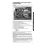
NOTES
Replacement of the refrigeration cycle.
1. When replacing the refrigerating cycle, be sure to discharge the refrigerant by using a refrigerant recovery system.
2. After discharging the unit completely, remove the desired components, and unbraze the pinch-off tubes.
3. Solder service valves into the pinch-off tube ports, leaving the valves open.
4. Solder the pinch-off tubes with service valves.
5. After doing the above procedures, the valve must be closed and left in place on the system for any subsequent
procedures.
6. Evacuate as follows:
6-1. Connect the vacuum pump, as illustrated figure 72A.
6-2. Start the vacuum pump. Slowly open manifold valves A and B with two full turns counterclockwise
the valves closed.
and leave
The vacuum pump is now pulling through valves A and B up to valve C by means of manifold and the entire
system.
CAUTION : If high vacuum equipment is used, just crack valves A and B for a few minutes, then open slowly
with the two full turns counter-clockwise. This will keep oil from foaming and being drawn into the vacuum
pump.
6-3. Operate the vacuum pump for 20 to 30 minutes, until 600 micron vacuum is obtained.
Close valves A and B and observe vacuum gauge for a few minutes.
A rise in pressure would indicate a possible leak or moisture remains in the system.
With valves A and B closed, stop the vacuum pump.
6-4. Remove the hose from the vacuum pump and place it on the charging cylinder. See figure 23B. Open valve C.
Discharge the line at the manifold connection.
6-5. The system is now ready for final charging.
7. Recharge as follows :
7-1. Rotary compressor systems are charged from the high-side. If the total charge cannot be put in the high-side,
the balance will be put in the suction line through the access valve which is installed as the system is opened.
7-2. Connect the charging cylinder as shown in figure 72B. With valve C open, discharge the hose at the manifold
connection.
7-3.
7-4.
7-5.
a.
b.
c.
Open valve A and allow the proper charge to enter the system. Valve B is still closed.
If more charge is required, the high-side will not take it. Close valve A.
With the unit running, open valve B and add the balance of the charge.
Do not add the liquid refrigerant to the low-side.
Watch the tow-side gauge, allow pressure to rise to 30 Ibs.
rum off valve B and allow the pressure to drop.
d. Repeat steps B and C until the balance of the charge is in the system.
7-6. When the unit is operating correctly, use the pinch-off tool with the unit stillrunning and the clamp on the
pinch-off tube. Using a tube cutter, cut the pinch-off tube about 2 inches from the pinch-off tool. Use sil-fos
solder and solder the pinch-off tube closed. rum off the unit, allow setting for a while and then test the leakage of the pinch-off connection.
---30--
Equipment needed: Vacuum pump, charging cylinder, manifold gauge, brazing equipment, pinch-off tool capable
of making a vapor proof seal, leak detector, tubing cutter, hand tools to remove components, service valve.
COMPOUND GAUGE
MANIFOLD
GAUGE
CONDENSER
(HIGH PRESSURE SIDE)
SEE
BELOW
COMPRESSOR
EVAPORATOR
(LOW PRESSURESIDE)
CAPILLARY TUBE
HI
CHARGING CYLINDER
EXTERNAL VACUUM PUMP
Figure 72B-Charging
Figum72A-PullingVacuum
m31--
3. INSTALLATION
- MODEL: 79053/79056
•
ITEM
B
HOW TO INSTALL
1. Insert the sliding panels (ITEM H) into the guides
of the air conditioner. Fasten the curtains to the
unit with screws (ITEM B), as shown in Figure 73.
ITEM S
Figure 73
2. Cut the adhesive-backed
the window width.
seal strip (ITEM E) to
Remove the backing from the seal strip and attach
the seal strip to the underside of the bottom window. (See Figure 74)
Figure 74
3. location of unit in window
• Open the window and mark center line on the
center of the INNER SILL as shown in Figure 75.
ROOM SIDE
Figure 75
4. Attach L bracket
INNER SILL
• The units install L bracket (ITEM G) center in
back of inner window sill, with short side of
bracket to the outside. Use the 2 screws (ITEM
ITEM A
_,
OUTER SILL
INSIDE
CENTER LINE
A) provided.
• Bracket helps to hold unit securely in place. Be
sure to place bracket edge flush against back of
inner sill. (See Figure 76)
OUTSIDE
Figure 76
5. INSTALL THE AIR CONDITIONER
DOW
IN THE WIN-
• Carefully liftthe air conditioner and slide it into the
open window. Make sure the bottom guide of the
air conditioner drops into the L bracket.
• When the air conditionerdrops into the L bracket,
the air conditionerwill be centered in window
opening as shown in Figure 77.
• While steadying the air conditioner,carefully bdng
the window sash down behind the upper guide of
.the air conditioner,as shown in Figure 78.
CENTER LINE
Figure 77
6. SECURE THE SLIDING PANELS
Extend the sliding panels to fill the window opening using 4 screws (ITEM C) to secure them, as
shown in Figure 79.
WINDOW FRAME
1/4_"
SEAL
7. INSTALL THE SASH SEAL AND SASH LOCK
• Cut the sash seal to the window width.
_=
Stuff the sash seal between the glass and the
window to prevent air and insects from getting
into the room, as shown in Figure 79.
• Screw the sash lock (ITEM D) on using an ITEM
B screw, as shown in Figure 79.
IF AIR CONDITIONER
WINDOW FRAME
UPPER GUIDE
BO'FI-OMGUIDE
Figure 78
IS BLOCKED BY STORM
• If storm window presents interference, fasten a 2"
wide wood strip to inner window sill across the full
width of the sill. Wood strip should be thick enough
to raise the height of the window sill so that the
unit can be installed without interference by the
storm window frame. See Figure 80.
Top of wood stdp should be approximately 3/4"
higher than storm window frame or wood strip
(OUTDOORS) to help unit condensation to drain
propedy to the outside.
• Install a second wood strip (approximately 6" long
1" wide and same thickness as first strip) in the
center of the outer sill flush against the back of the
inner sill. This will raise the L bracket as shown in
Figure 80.
• If the distance between "STORM WINDOW
FRAME" and "WOOD STRIP MOUNTED ON TOP
Sash lock
Sash seal
(ITEM F)
Figure 79
WOOD STRIP MOUNTED
ON TOP OF
OF INNER SILL" is more than 1", two wood stdps
I" MAX.
CLEARANCE _
INNER
SILL
are not necessary.
OUTER
SILL
3.2 AIR CONDITIONER
REMOVAL
INDOORS
IOUTDOORS
Figure 80
Turn the air conditioner off, disconnect the power
cord, remove the sash lock and the screws installed
through the top and bottom of the sliding panels.
Save all parts for later reinstallation. Close the sliding panels. Keeping a firm gdp on the air conditioner, raise the sash, and carefully tilt the air conditioner backward, draining any condensed water. Lift the
air conditioner from the window. Remove the sash
seal from between the windows.
• Air conditionemcoveredin this manualpose an excessive weighthazard.Two or more peopleare neededto
move and installthe unit.
To preventinjuryor strain,use properliftingand carrying techniqueswhen movingunit.
• When handlingthe air conditioner,be carefulto avoid
cuts fromsharpmetalfins on frontand rear coils.
• Make sure air conditionerdoes not fall duringremoval.
--33--
• MODEL:
79074/79122
HOW TO INSTALL
1. Remove the screws which fasten the cabinet at
both sides and at the back.
Figure 81
2. Slide the unit out of the cabinet by gripping the
base pan handle and pull forward while bracing
the cabinet.
Figure 82
3. Cut the FOAM-PE ® to fit the underside of the
window sash. Peel off the backing and attach the
seal as shown in Figure 83.
Figure 83
4. Insert the side curtain _ into the upper guide and
lower guide of the air conditioner. Fasten the curtains to the unit with (8) TYPE A screws _).
Upp_
(TYPEA}
Figure 84
5. Open the window. Mark a line on center of the
window stool (or desired air conditioner location).
Carefully place the cabinet on the window stool
and align the center mark on the angle front with
the center line marked in the window stool.
Upper guide
Figure 85
't angle
WINDOW SASH UPPER GUIDE
6. Pull the bottom window sash down behind the
upper guide until it meets.
NOTE: Do not pull the window sash down so tightly
that the movement of side curtain is restricted.
CABINET
SIDE CURTAIN (_)
Figure 86
7. Loosely assemble the sill support using the parts
in Figure 87.
Sill Support@
_ Nut(_)
Figure 87
--34---
Bolt(_)
A)(_)Screw(Type
8. Select the position that will place the sill supports
near the outer most point on sill (See Figure 88).
Attach the sill supports to the cabinet track hole in
relation to the selected position using TYPE A
screw @.
_
g
Cabinet
OUTDOOR
fNDOOR
Figure 88
9. Place the sill supports with the cabinet on the window sill's selected position.
10. The cabinet should be installed with a very slight
tilt (about 1/4") downward toward the outside
(See Figure 89).
Adjust the bolts and the nuts of sill supports to
level the cabinet.
Figure 89
Track
11. Attach the cabinet to the window stool by ddving
the TYPE B screws ® through the front angle
into window stool.
Front Angle
Figure 90
Sill Support
Screw(Type B) (_
(_)
12. Pull the window sash down behind the upper
guide. Pull each side curtain fully to each sash
track.
Screw
.,.(Type C)(_
13. Attach each side curtain to the window sash
using TYPE C screws (_ (See Figure 91)
Screw
Figure 91
14. Attach the window locking bracket _ with TYPE
C screw ® (See Figure 92)
Figure 92
15. Slide the chassis into the cabinet.
(See Figure 93)
CAUTION: For security purpose, reinstall
screws at cabinet's sides.
Cord
Screw
16. Cut the foam seal ® to the proper length and
insert between the upper window sash and the
lower window sash. (See Figure 94)
Figure 93
Figure g4
--35--
Screw
17. The vent control handle must be straightened
before the decorative front is attached. Pull down
part ® to align with part ®.
•
/
18. FRONT INSTALLATION
Vent Control Installation
• Hook upper tabs of front grille into slots on the
cabinet top. (See Figure 96)
• Push front grille towards the cabinet in order to
snap side tabs into the cabinet. (See Figure 96)
• Open the filter door. (See Figure 97)
• Tighten the TYPE A screw @ through the front
Installing Bottom Rail Seal
Figure 95
gdlle. (See Figure 97)
• Close filter door. (See Figure 98)
Figure 96
Front Installation
19. If AIR CONDITIONER is Blocked by Storm Window FRAME, add wood to clear frame as shown
@
in Figure 99, or remove storm window frame
while air conditioner is installed.
3.4 AIR CONDITIONER
Figure 97
FrontInstallation
Figure 98
FrontInstallation
REMOVAL
Turn the air conditioner off, disconnect the power
cord, remove the window locking bracket and the
screws installed through the top and bottom of the
side curtains. Save all parts for later reinstallation.
Close the side curtains. Keeping a firm gdp on the
air conditioner, raise the sash, and carefully tilt the
air conditioner backward, draining any condensed
water. Lift the air conditioner from the window.
Remove the sash seal from between the windows.
g
1 V2_min
• Air conditioners covered in this manualpose an excessive weighthazard.Two or more people are needed to
moveand installthe unit.
To preventinjuryor strain,useproperlifting]and carryingtechniqueswhen movingunit.
• When handlingthe air conditioner,be carefulto avoid
cutsfromshaq:)metalfins on frontand rear coils.
Stormwindowframe--_
or otherobstnJction
Wood block in area -of leveling support
_,_.Makesure air conditionerdoes not fall duringremoval.
Figure 99
---36---
thickness as
, along
entirestool.
Fastenwithtwo
nailsor screws.
• MODEL: 79184/79188
3.5 HOW TO INSTALL
1. Remove the screws which fasten the cabinet at
the back and side of the unit.
Figure 100
2. Slide the unit out of the cabinet by gripping the
base pan handle and pull forward while bracing
the cabinet.
3. Cut the Foam-PE (_ to fit the underside of the
window sash. Peel off the backing and attach the
Figure 101
Foam-PE as shown in Figure 102.
Figure 102
4. Insert the side curtain (_ into the upper guide and
lower guide of the air conditioner. Fasten the curtains to the unit with TYPE A screws @.
(TYPEA)
5. Open the window. Mark a line on the center of the
window stool between the side window stop moldings. Loosely attach the sill bracket to the supped
bracket using the carriage bolt and the lock nut.
6. Attach the sill bracket to the window sill using the
TYPE B screws ®. Carefully place the cabinet on
the window stool and align the center mark on the
Figure 103
Sill
bracket
Cardage
bolt
er edge of the window sill. Tighten the carriage
bolt and the lock nut. Be sure the cabinet slants
outward 1/4 bubble using the carpenters level.
CAUTION: Do not drill a hole in the bottom pan. The
unit is designed to operate with approximately 1/2"of water in bottom pan.
bracket
•_
Lock nut
Figure 104
angle front with the center line marked on the window stool.
7. Using the M-screw ® and the lock nut _), attach
the support bracket to the cabinet track hole. Use
the first track hole after the sill bracket on the out-
) (TYPEA)
Machinescrew
locknut
Outer
edgeof
windowsill
Cabinet
track hole
bracket
Carriagebolt
andlock nut
®
Sill
Figure 105
Upper guide-_-
_/_/__LSide
_
Figure 106
---37--
l Window
windowstop
molding
too,
8. Pull the bottom window sash down behind the
Window sash
upper guide until they meet.
NOTE:
• Do not pull the window sash down so tightly that
the movement of sliders is restricted. Attach the
cabinet to the window stool by driving the TYPE B
screws ® through the cabinet into window stool.
• The cabinet should be installed with a very slight
tilt downward toward the outside 1/4 bubble on car-
Top retainer bar
Foam-PE 4
Cabinet
Frame curtain
Foam-PE
Figure
• Screw (_
(Type B)
107
penters level.
Screw
(_)
9. Expand side curtains to fill opening.
Attach each side curtain to the window sash using
(4) TYPE C screws O (See Figure 108)
Figure 108
(Type C)
10. Attach the window locking bracket @with a
type C screw ® (See Figure 109)
Figure 109
11. Slide the chassis into the cabinet. (See Figure
110)
CAUTION: For security purpose, reinstall screws at
cabinet's sides.
Cord
Screw
Figure 110
Screw
12. Cut the foam seal @to the proper length and
insert between the upper window sash and the
lower window sash. (See Figure 111)
Figure 111 _1
(_)
13. Adjust the vent handle before the decorative
front is attached. (See Figure 112)
Straighten the lever, as shown. Pulling down
part ® to align with part _).
CLOSE ,ak VENT JL OPEN
Figure 112
__q_
I
_'_ '_' _'_"_
14. Front Installation
install the front grille with the cabinet as follows:
• Hook upper tabs of front grille into slots on the
cabinet top. (See Figure 113)
• Push front grille's tips toward the cabinet in order
to snap side tabs into the cabinet. (See Figure
113)
• Open the filter door. (See Figure 114)
• Install the TYPE A screw (_ through the front
Front Installation
Figure 113
grille. (See Figure 114)
• Close filter door. (See Figure 115)
Screw®
IF AIR CONDITIONER
WINDOW FRAME
IS BLOCKED BY STORM
Add wood to clear front as shown in Figure 116, or
remove storm window while air conditioner is
installed.
3.6 AIR CONDITIONER
Figure 114
Front Installation
Figure 115
Front Installation
REMOVAL
Turn the air conditioner off, disconnect the power
cord, remove the window Ioking bracket and the
screws installed through the top and bottom of the
side curtain. Save all parts for later reinstallation.
Close the side curtain. Keeping a firm grip on the air
conditioner, raise the sash, and carefully tilt the air
conditioner backward, draining any condensed
water. Lift the air conditioner from the window.
Remove the sash seal from between the windows.
ash
Woodblock
1 l/2"min
in areaof_ _(38r_)___L
leveling i]_t,r_
support_Lt_p y " r_
1
J_
I Board thicknessas
I _
required,along
Stormwindowframe
entirestool.
or otherobstruction
Fastenwithtwo
nailsor screws.
• Airconditionerscovered in this manualpose an
excessiveweighthazard.Two or more people
are needed to moveand installthe unit.
To preventinjuryor strain,use properliftingand
carryingtechniqueswhen movingunit.
• When handlingthe air conditioner, becareful to
avoidcutsfromsharp metal fins on front and
rear coils.
• Make sure air conditioner does notfall during
removal.
Figure 116
---39 m
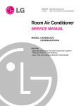
4. TROUBLESHOOTING
4.1 OUTSIDE
• MODELS:
DIMENSIONS
79053/79056
GUIDE
(Unit : mm)
• MODEL:
79074
13 7/8"
L
19 3/6"
• MODEL:
79122
• MODELS:
16
14 31132"
----413---
27/3,?."
79184179188
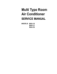
4.2 PIPING SYSTEM
/
)-
(
--
CONDENSER COILS
--
FAN
\
CAPILLARY
TUBE
--
MOTOR
BLOWER
_--
T-
--=
I
EVAPORATOR
COILS
Following is a brief descdption of the important components and their function in what is called the refrigeration
system. Reference should be made to Figure 117 to follow the refrigerating cycle and the flow of the refrigerant in
the cooling cycle.
ROOM AIR CONDITIONER
CYCLE OF REFRIGERATION
EVAPORATORCOILS
CONDENSERCOILS
SUCTION
COMPLETE
LIQUID
LINE
COOL LOW PRESSURE
VAPOR
INLET
-HOT
_SCHARGED
AIR
VAPOR
i
oo.s,RE
DROP
MOULD OUTLET
_
_
(UQGID REFRIGERANT)
i
" uQUID OUTLET
HIGH PRESSURE
CAPILLARy
TUBE
I'_
LIQUID
LOW PRESSURE
Figure 117
--41 m
VAPOR
REFRIGERANT
VAPOR
4.3 TROUBLESHOOTING
GUIDE
In general, possible trouble is classified in two kinds.
The one is called Starting Failure which is caused from an electrical defect. The other is Ineffective Air
Conditioning caused from a defect in the refrigeration circuit and improper application.
UNIT
IS RUNNING
BUT
COOLING
IS INEFFECTIVE.
1
Ineffective Cooling
I I
increase.
I
I
Clean condenser.
1
I
Not on separate circuit
I
I
Check outdoor coil
I
circulation for smooth
(heat exchanger) and
flow.
fan operation,
(heat
exchanger)
Dirty indoor
coil
I
I
I
I
I
I
Repair gas leak.
I
I
Replacement of unit if
I
Clogging of air filter.
I
the unit is beyond repair.
{
I
Check inside gas
pressure.
Adjust refrigerant
Obstruction at air outlet.
I
charge.
Remove obstruction.
Malfunction of
compressor.
Check clogging in refrigeration circuit.
Repair clogging in
refrigeration circuit,
Replacement of
compressor.
Satisfactory operation
with temperature
difference of inlet & outlet
air; 44---50°F (7-10°C)
1
i
I
Fails to Stad
I
Check of power source.
]
Check of circuit breaker
and fuse.
{
|
Check of control switch
/
Gas leakage of feeler
bulb of thermostat.
setting.
Check control switch.
_r
Compressor fails only to
start.
L
Fan only fails to start.
IImproper wiring.
I
Drop of power voltage.
settingImproper
thermostat
l
connection
Loose terminal
capacitor.
Defect of compressor
I
I
capacitor.
Defect of fan motor
Capacitor check.
<--
Replacement.
I<--
Irregular motor
resistance ( Q )
Irregular motor"
insulation ( Q )
Improper wiring
Replacement of fan motor.
I
Regular but fails to start.
Replacement of compressor.
(Locking of piston, metal.)
Replacement of compressor
(Motor damaged).
--43--
COMPLAINT
-'an motor will not run.
CAUSE
REMEDY
No power
Check voltage at outlet. Correct if none.
Power supply cord
Check voltage to rotary switch. If none, check
power supply cord. Replace cord if circuit is
open.
Check switch continuity. Refer to widng diagram
for terminal identification. Replace switch ff
Rotary switch
defective.
Wire disconnected or
Connect wire. Refer to wiring diagram for
connection loose
terminal identification. Repair or replace loose
terminal.
Capacitor. (Discharge
capacitor before testing.)
Test capacitor.
Replace if not within -t-10% of manufacturer's
rating. Replace if shorted, open, or damaged.
Will not rotate
Fan blade hitting shroud or blower wheel hitting
scroll. Re-align assembly.
Units using slinger ring condenser fans must
have 0.22-0.25 inch clearance to the base. If it is
the base, shim up the bottom of the fan motor
with mounting screw(s).
Check fan motor bearings; if motor shaft will not
rotate, replace the motor.
Fan motor runs.
Check voltage. See limits on this page.
Revolves on overload.
If not within limits, call an electrician.
Test capacitor.
Check bearings. Does the fan blade rotate freely?.
If not, replace fan motor.
Pay attention to any change from high speed to
low speed. If the speed does not change,
replace the motor.
---44---
CAUSE
COMPLAINT
Fan motor noise.
REMEDY
_n
If cracked, out of balance, or partially missing,
replace it.
Blower
If cracked, out of balance, or partially missing,
replace it.
Loose set screw
Tighten it.
Worn bearings
If knocking sounds continue when running or
loose, replace the motor. If the motor hums or
noise appears to be internal while running,
replace motor.
Compressor will not run,
fan motor runs.
Voltage
Check voltage. See the limits on the preceding
page. If not within limits, call an electrician.
Wiring
Check the wire connections; if loose, repair or
replace the terminal. If the wires are disconnected, refer to wiring diagram for identification,
and replace the wires. Check the wire connections
If not according to the widng diagram, correct
the connections.
Rotary Switch
Check for continuity, refer to the widng diagram
for terminal identification. Replace the switch if
the circuit is open.
Thermostat
Check the position of knob. If not at the coldest
setting, advance the knob to this setting and
restart the unit.
Check the continuity of the thermostat. Replace
the thermostat if the circuit is open.
Compressor cycles on
ovedoad.
Capacitor (discharge
capacitor before
servicing.)
Check the capacitor.
Replace if not within_+10% of manufacturer's
rating, replace if shorted, open, or damaged.
Compressor
Chock the compressor for open circuit or
ground. If open or grounded, replace the
compressor.
Ovedcad
Check the compressor overloadif extemallymounted.
Replace if open. (If the compressortemperature is
high, remove the overload, cool and retest.)
Voltage
Check the voltage. See the limits on the
preceding page. If voltage is not within these limits
call an electrician.
Ovedoad
Check overload, if externally mounted.
Replace if open. (If the compressor temperature
is high, remove the ovedoad, cool, and retest.)
--45--
CAUSE
COMPLAINT
Compressor cycles on
overload
REMEDY
Fan motor
If not running, determine the cause. Replace if
required.
Condenser air flow
restriction
Remove the cabinet, inspect the interior surface
of the condenser. If restricted, clean carefully
with a vacuum cleaner (do not damage fins) or
brush. Clean the interior base before
re-assembling.
Insufficient cooling.
Excessive noise.
Condenser fins
If the condenser fins are closed over a large
(damaged)
area on the coil surface, head pressures will
increase, causing the compressor to cycle.
Straighten the fins or replace the coil.
Capacitor
Test the capacitor.
Wiring
Check the terminals. If loose, repair or replace.
Refrigeration system
Check the system for a restriction.
Air filter
If restricted, clean or replace.
Unit undersized
Determine if the unit is propedy sized for the
area to be cooled.
Blower or fan
Check the set screw, or clamp. If loose or missing, correct. If the blower or fan is hitting scroll
or shroud, rearrange the air handling parts.
Remove the cabinet and carefully rearrange the
Copper tubing
tubing not to contact the cabinet,
compressor, shroud, and air guide.
---46--
5. CIRCUIT DIAGRAM
• MODEL : 79053
F
POWER INPUT
BK(BR)
Q
WH(BL)
(Plain)
|
(Ribbed)
i-- - __GN(GN/YL)
CAPACITOR
OR(I_R)
BK
RD
BL
BR
THERMOSTAT
LOCATION
DESCRIPTION
NO.
1
COMPRESSOR
2
CAPACITOR
3
FAN MOTOR
4
SPRINGCLIP(FORBLOWER,FAN)
5
t
PART NO.
Q'TY
79053
=ERSET
5416A20001B
1
6120AR2194A(4+25pF,
370/400VAC)
1
4681A20001A
1
3H02932B
1
BLOWER
5834AR1592A
1
6
FAN
5900AR1594A
1
7
THERMOSTAT
2H01109H
1
8
ROTARY SWITCH
2H00154H
1
9
OVERLOAD PROTECTOR
6750U-L004A(M
---47--
RA98703-12026)
1
• MODEL : 79056
POWER INPUT
WH(BL) _
BK(BR)
(Ribbed) _
(Plain)
-_N(GN/YL)
--
THERMISTOR
CAPACITOR
/
OR(BR)
'_
BK
COMP.
BL
OLP
-_SE 1?_5v2A
J
LOCA'n0N
PART NO.
DESCRIPTION
Q'TY
79056
NO.
1
COMPRESSOR
2
CAPACITOR
3
FAN MOTOR
4
SPRINGCUP(FOR BLOWER,FAN)
5
• PER
SE/
5416A20001D
6120AR2194A(4+25pF,
370/400VAC)
1
1
4681A20001A
1
3H02932B
1
BLOWER
5834AR1592A
1
6
FAN
5900AR1594A
1
7
MAIN PCB
6871 A20037F
1
8
DISPLAY PCB
6871A30004A
1
9
OVERLOAD
6750U-L004A(M RA98703-12026)
1
PROTECTOR
---48---
• MODEL : 79074
f
POWER INPUT
BK(BR)
(Plain),
ROTARY SWITCH
Q
WR(BL)
/
(Ribbed)
,- - -IGN(GN/YL)
CAPACITOR
BR
:RD
IBK
OLP
P.T.C
LOCA'nON
DESCRIPTION
NO.
L
1
COMPRESSOR
2
CAPACITOR
3
FAN MOTOR
4
SPRING CUP(FOR BLOWER;FAN)
5
PART NO.
Q'TY
79074
PERSET
5416A20004B
1
6120AR2194C(4+30pF,
370/400V)
1
681A2.0010C
1
3H02932B
1
BLOWER
5834AR 1168B
1
6
FAN
5900AR1167B
1
7
THERMOSTAT
2H01109H
1
8
ROTARY SWITCH
2H00154H
1
9
OVERLOAD PROTECTOR
6750U-L030A(MRA98965-12027)
--49--
1
° MODEL : 79122
POWER INPUT
BK(BR)
(Plain),
ROTARY SWITCH
RD
@
,
WH(BL)
|
(Ribbed)
: - - -_.__GN(GN,_L)
M
RL
J
L0CATION
PART NO.
DESCRIPTION
79122
NO.
1
2
OW
5416AR2300Q
COMPRESSOR
I CAPACITOR
3
FAN MOTOR
4
SPRINGCUP(FOR BLOWER,FAN)
5
_R$_
6120AR2194K(6+45pF,
1
370/400V)
1
4681A20009A
1
3H02932B
1
BLOWER
5834AR1495A
1
6
FAN
5900AR1173A
1
7
THERMOSTAT
2H01109H
1
8
ROTARY SWITCH
2H00598E
1
9
OVERLOAD PROTECTOR
6750U-L029A(MRA12053-12027)
--50--
1
• MODEL : 79184
POWER INPUT
ROTARY SWITCH
BK(BR)
Q
WH(BL)
(Plain)
|
(Ribbed)
i--- GNIY,
CAPACITOR
BL
THERMOSTAT
J
LOCATION
DESCRIPTION
NO.
1
COMPRESSOR
2
CAPACITOR
3
FAN MOTOR
4
SPRINGCLIP(FORBLOWER, FAN)
5
PART NO.
QqX
79184
PER
SET
5417AR2652A
1
6120AR2194D(6+30pF,
370/400VAC)
1
4681AR6033B
1
3H02932C
1
BLOWER
5834AR1599A
1
6
FAN
5900AR1508A
1
7
TH ERMOSTAT
2H01109L
1
8
ROTARY SWITCH
2H00598E
1
• MODEL : 79188
POWERINPUT
WH(BL) _
BK(BR)
i ......................-_j_GN<G_,_
"r.E.MISTOR
, BK
MOTOR
CAPACITOR
OR(BR)
::h
L0cA'n0N
DESCRIPTION
NO.
1
COMPRESSOR
2
CAPACITOR
3
; FAN MOTOR
PART NO.
Ol"Y
79188
PER
SEI
5417AR2652A
1
6120AR2194D(6+30pF,
370/400VAC)
I
4681AR6033B
1
3H02932C
I
4
SPRING CLIP(FORBLOWER,FAN)
5
BLOWER
5834AR1599A
I
6
FAN
5900AR1508A
1
7
MAIN PCB
6871A20037J
I
8
DISPLAY PCB
6871A30012A
I
---52--
i<.
• MODEL: 79053(PARTS
LOCATION
NO.
LIST)
DESCRIPTION
PART NO.
79053
CABINET ASS'Y
3091AR6055E
2
KNOB ASS'Y
4941AR3813A
3
GRILLE, INLET
3530AR1343A
4
AIR FILTER ASS'Y
5231AR2148A
5
GRILLE, FRONT
3530AR 1344A
6
VANE
5990AR3190B
7
VANE
5990AR3190A
8
LINK HOLDER
4520AR3191A
*
OWNER'S MANUAL
3828AR7217C
A-1
POWER CORD ASS'Y
2H00677P
2
HOLDER-POWER
4H01254A
3
CONNECTOR
ASS'Y
6631AR3843K
4
CONNECTOR
ASS'Y
6877A20001A
5#
THERMOSTAT
2H01109H
6#
SWITCH, ROTARY
2H00154H
CLAMP, CAPACITOR
4H00442N
B-1 #
7
8#
9
C-1 #
2
CORD
CAPACITOR, SH(4+25pF,
370/400VA0)
6120AR2194A
CONTROL BOARD
4994AR2149A
EVAPORATOR ASS'Y
5421A20016A
CLAMP, SPRING
3H02932B
BLOWER
5834AR15.92A
4
AIR GUIDE
5238AR1591A
5
SCROLL
3072AR1589A
6
BASE WELD ASS'Y
3041AR6199K
MOTOR ASS'Y
4681A20001A
8
ORIFICE
4948AR6166A
9
SHROUD
4998AR1608A
10 #
FAN
5900AR1594A
11 #
CONDENSER ASS'Y
5403AR6200A
3 #
7 #
# = Functional Parts
* = Non-Illustrated Parts
LOCATION
NO.
D-1
PART NO.
DESCRIPTION
79053
NUT, TERMINAL COVER
4H00947A
2
GASKET NUT
4H01058A
3
TERMINAL COVER
3550-CL001D
4
OVERLOAD PROTECTOR SPRING
4970U-L002A
OVER LOAD PROTECTOR
6750U-LO04A
GASKET
4986U-L001 B
COMPRESSOR
5416A20001B
8
HEXAGON NUTS
1NHA0801206
9
BRACKET, WASHER
4810AR4155B
10
RUBBER, MOUNTING
5040AR4195A
11
TUBE EVA-IN
5210A30124A
12
CAPILLARY, FORM
5210A30018B
13
TUBE FORMED-C ASS'Y
5211AR3332A
14
TUBE SUCTION ASS'Y
5211AR6204C
15
TUBE, DISCHARGE
5210A30001C
FRAME CURTAIN ASS'Y, LEFT
3211AR3239B
2
FRAME CURTAIN ASS'Y, RIGHT
3211AR3239A
3
"L" BRACKET
4810A40002A
4
ROUND HEAD SCREW
1DRC0513118
5#
6
7#
E-1
# = Functional Parts
* = Non-Illustrated Parts
--55---
_<
13
2
1
11--
7
i
L
° MODEL: 79056(PARTS
LOCAT]ON
NO.
LIST)
PART NO.
DESCRIPTION
79056
CABINET ASS'Y
3091AR6055E
2
LOUVER, HORIZONTAL
5990A20001A
3
GRILLE, INLET
3530A10010A
4
AIR FILTER ASS'Y
5231AR2148A
5
GRILLE, FRONT
3530A10009A
6
VANE
5990A30005B
7
VANE
5990A30005A
8
LINK HOLDER
4520AR3191A
OWNER'S MANUAL
3828AR7217Z
REMOTE CONTROL
6711AR2700J
A-1
9
POWER CORD ASS'Y
2H00677P
2
HOLDER-POWER
4H01254A
3
CONNECTOR
4
BOARD CONTROL
3500A20001A
5
THERMISTOR
6323AQ2333K
6
LEAD WIRE ASS'Y
6631AQ3201B
7 #
TRANSFORMER,
6171AQ2258G
8 #
CAPACITOR, SH(4+2_F,370/400VAC)
6120AR2194A
9
CONTROL BOX
4994A10003A
10
PANEL, CONTROL
3720A20017A
11
PWB ASS'Y, DISPLAY
6871A30004A
12
PWB ASS'Y, MAIN
6871A20037F
EVAPORATOR ASS'Y
5421A20016B
B-1 #
C-1 #
2
CORD
6631AR3843K
ASS'Y
POWER
3H02932B
CLAMP, SPRING
BLOWER
5834AR1592A
4
AIR GUIDE
5238AR1591A
5
SCROLL
3072AR1589A
6
BASE WELD ASS'Y
3041AR6199K
MOTOR ASS'Y
4681A20001A
3#
7#
# = Functional Parts
* = Non-Illustrated
Pads
--57 D
PART NO.
L0CA_0N
NO.
DESCRIPTION
79056
8
ORIFICE
4948AR6166A
9
SHROUD
4998AR1608A
10 #
FAN
5900AR1594A
11 #
CONDENSER ASS'Y
5403A20009A
NUT, TERMINAL COVER
4H00947A
2
GASKET NUT
4H01058A
3
TERMINAL COVER
3550-CL001D
4
OVERLOAD PROTECTOR SPRING
4970U-L002A
OVER LOAD PROTECTOR
6750U-L004A
GASKET
4986U-L001B
COMPRESSOR
5416A20001D
8
HEXAGON NUTS
1NHA0801206
9
BRACKET, WASHER
4810AR4155B
10
RUBBER, MOUNTING
5040AR4195A
11
TUBE EVA-IN ASS'Y
5211A30115A
12
CAPILLARY, FORM
5210A30018B
13
TUBE FORMED-C ASS'Y
5211AR3332A
14
TUBE SUCTION ASS'Y
5211A30116A
15
TUBE, DISCHARGE
5210A30001C
FRAME CURTAIN ASS'Y, LEFT
3211AR3239B
2
FRAME CURTAIN ASS'Y, RIGHT
3211AR3239A
3
"L" BRACKET
4810A40002A
4
ROUND HEAD SCREW
1DRC0513118
D-1
5 #
6
7 #
E-1
# = Functional Parts
* = Non-lUustrated Parts
---58--
P,
16
15
• MODEL: 79074(PARTS
LIST)
PART NO.
.0_).1_
79O74
DESCRIPTION
3530AR1532A
A-1
FRONT GRILLE
2
I AIR FILTER ASS'Y
3
I INLET GRILLE
4
I VANE
5
I LOUVER
6
/ KNOBASS'Y
7
*
/ CABINET ASS'Y
/ MANUAL OWNER'S
B-1
CONTROL BOX
4994ARll 66C
CONTROL BOX COVER
4994AR3579A
2
5230AR2976A
3530AR1533A
5990AR2973A
4758AR3330A
4941AR7134C
3091AR2317C
3828AR7289X
3#
ROTARY SWITCH
2H001,54H
4#
THERMOSTAT
2H01109H
5#
CAPACITOR, SH
6120AR2194C
CAPACITOR CLAMP
4H00442F
POWER CORD ASS'Y
2H00677R
8
HOLDER PC
4H01762A
9
CONNECTOR
ASS'Y
6877A20001 C
10
CONNECTOR
ASS'Y
6631AR2667H
6
7#
c-ll
2t
BASE PAN WELD ASS'Y
3041AR2306R
LOWER AIR GUIDE ASS'Y
5239AR3398A
I
4900AR3324A
I DAMPER
3
I
4
I MOTOR MOUNT
4960AR6151A
s#l
MOTOR ASS'Y
4681A2.0010C
BLOWER
5834AR1168B
SHROUD
4998AR1163A
FAN
5900AR1167B
8#1
91
CLAMP SPRING
lol
UPPER AIR GUIDE ASS'Y
6239AR3401A
11
EPS COVER
3550AR2334A
3H02932B
# = Functional Parts
* = Non-Illustrated Parts
---6O---
PART NO.
L0CAT_N
NO.
DESCRIPTION
79074
12 #
EVAPORATOR ASS'Y
5421AR2998A
13#
CONDENSER
ASS'Y
5403AR2473A
14
REAR WIRE GRILLE
3530AR2332B
15
HOLE RUBBER
4H02023A
16
WASHER, RUBBER
4H01029D
17
DRAIN PIPE
3H02773A
D-1
ANTI-VIBRATION
4H00982C
BUSH
2
BRACKET, WASHER
4810AR415SB
3
HEXAGON NUTS
1NHA0801206
COMPRESSOR
5416A20004B
5
GASKET
4986U-L001G
6
CONNECTOR ASS'Y
6631AR2668F
OVERLOAD PROTECTOR
6750U-L030A
8
SPRING,OVERLOADPROTECTOR
4970U-L002A
9
TERMINAL COVER
3550U-L002D
10
GASKET NUT
4H01058A
11
TERMINAL COVER NUT
4H00947A
12
TUBE DISCHARGE
5210A30118A
13
TUBE ASS'Y, SUCTION
5211AR2309A
14
TUBE FORMED
5210AR2311A
15
TUBE ASS'Y, FORMED
5211AR3399A
16
CAPILLARY, FORMED
5424AR3548A
E-1
4974AR3328B
4974AR3328B
2
4959AR3402A
4959AR3402A
3
4959AR:3402B
4959AR3402B
4
4810AR3240A
4810AR3240A
5
1BHD1004006
1BHD1004006
6
1NHCl000006
1NHC1000006
7
4H01785B
4 #
7 #
4H01785B
# = Functional Parts
* = Non-Illustrated
Parts
--.61 m
[]
17
Ira.
_<
i I
I
i
11
3
13
10
1
.....
I
• MODEL: 79122(PARTS
LOCATION
NO.
LIST)
PART NO.
DESCRIPTION
79122
FRONT GRILLE
3530AR1534A
2
INLET GRILLE
3530AR1535A
3
AIR FILTER ASS'Y
5231AR1152A
4
VANE
5990AR2974A
5
LOUVER
4758AR7211A
6
KNOB ASS'Y
4941AR7134B
7
CABINET ASS'Y
3091AR2286M
MANUAL OWNER'S
3828AR7289Y
B-1
CONTROL BOX
4994AR1494D
2 #
CAPACITOR
6120AR2194K
A-1
3
CAPACITOR CLAMP
4H00442F
4 #
POWER CORD ASS'Y
2H00677S
5 #
THERMOSTAT
2H01109H
6 #
ROTARY SWITCH
2H00598E
7
HOLDER PC
4H01762A
8
COVER, CONTROL BOX
3550AR7032A
9
CONNECTOR ASS'Y
6631AR2667E
10
CONNECTOR ASS'Y
6631AR2687A
BASE PAN WELD ASS'Y
3041AR1524F
2
AIR GUIDE
5238AR1499A
3
ORIFICE
4948AR7034A
4
VENTILATION DAMPER
4900AR7024A
5
MOTOR MOUNT
4960AR6165A
MOTOR ASS'Y
4681A20009A
SCROLL
3072AR1498A
8 #
BLOWER
58.34AR 1495A
9 #
FAN
5900AR1173A
C-1
6 #
7
lo I c pSPR
'NG
11 I SHROUd%
# = Functional Pad_
* = Non-Illustrated Parts
3H02932B
4998AR1496A
LOCA110N
NO.
PART NO.
DESCRIPTION
79122
BRACE
4810AR7029A
13 #
EVAPORATOR ASS'Y
5421AR2994A
14 #
CONDENSER
5403AR2921A
12
ASS'Y
15
HOLE RUBBER
4H02023A
16
WASHER RUBBER
4 H01029 D
17
DRAIN PIPE
3H02773A
18
BARRIER
4790AR 1493A
19
RUBBER INSERT
5040AR4254A
20
REAR WIRE GRILLE
3530AR2688B
D-1
ANTI-VIBRATION
4984AR4361A
2 #
COMPRESSOR
BUSH
5416AR2300Q
4H01811C
3
BRACKET, WASHER
4
HEXAGON NUTS
1NHA0801206
5
GASKET
4986U-L001B
OVERLOAD PROTECTOR
6750U-L029A
7
SPRING
4970U-L002A
8
TERMINAL COVER
3550U-L002D
9
GASKET NUT
4H01058A
10
TERMINAL COVER NUT
4H00947A
11
CONNECTOR
12
TUBE ASS'Y DISCHARGE
5211AR2930A
13
TUBE ASS'Y SUCTION
5211AR2926D
14
TUBE FORMED EVAPORATOR
5210AR4358A
15
TUBE FORMED EVAPORATOR
5210AR7060A
16
TUBE FORMED CONDENSER ASS'Y
5211ART059A
17
TUBE ASS'Y CAPILLARY
5425AR7133A
UPPER GUIDE
4974AR3262E
2
SIDE CURTAIN ASS'Y
4959AR3402C
3
SIDE CURTAIN ASS'Y
4959AR3402D
4
SILL SUPPORT BRACKET
4810AR3240A
5
BOLT
1BHD1004O06
6
NUT
1NHC1000006
7
WINDOW LOCKING BRACKET
6 #
E-1
Fwnctional Parts
ASS'Y
6631AR2668E
* = Non-Illustrated
4H01785B
Parts
_64--
[]
i
2
16 11 9
10
8
5
11
12
14
• MODEL: 79184(PARTS
LOCATION
NO.
A-1
LIST)
PART NO.
DESCRIPTION
79184
FRONT GRILLE
3530AR1248A
2
INLET GRILLE
5236AR1531A
3
AIR FILTER ASS'Y
5230AR1327A
4
VANE
5990AR2972A
5
KNOB ASS'Y
4941AR7134A
6
CABINET ASS'Y
3091AR6057C
7
LOUVER
4758A30001A
*
MANUAL OWNER'S
3828A30016B
B-1
CONTROL BOX
4994AR1587E
2 #
CAPACITOR
6120AR2194D
3
CAPACITOR CLAMP
4H00442F
POWER CORD ASS'Y
2H00677Q
CLIP CORD
4H01762A
6 #
THERMOSTAT
2H01109L
7 #
ROTARY SWITCH
2H00598E
8 #
CONNECTOR
4 #
5
ASS'Y
6631AR2687A
9
LEAD WIRE ASS'Y
6877A20002A
10
COVER, CONTROL BOX
3550AR7245A
ASE PAN WELD ASS_'
3041A30002K
2
AIR GUIDE
5238AR1584A
3
SCROLL
3072AR1583A
4
BARRIER
4790AR1558A
5
DAMPER
4900AR7265A
6
MOTOR MOUNT
4960AR1596A
MOTOR ASS'Y
4681AR6033B
INSULATION, EPS
3040AR6160A
9 #
BLOWER
5834AR1599A
10 #
FAN
11 #
CLAMP SPRING
C-1
7 #
8
. 5900AR1508A
3H02932C
12
BSHROUD
4998AR1597A
13
BRACE
4800AR7272A
EVAPORATOR ASS'Y
5421A20017B
14 #
•l==,n,'tional Parts
* = Non-lUustrated Parts
---66--
PART NO.
L0CAI10N
NO.
DESCRIPTION
79184
CONDENSER ASS'Y
5403A20004F
16
ORIFICE
4948AR7241A
17
COVER, SHROUD
3550AR6173A
18 #
WASHER RUBBER
4H01029F
19
DRAIN PIPE
3H02773A
20
PIPE ELBOW
4H00261A
21
HOLE RUBBER
4H02023A
22
GRILLE, REAR
3530A20002B
D-1
ANTI-VIBRATION
2 #
COMPRESSOR
15#
BUSHING
4H00982C
ASS'Y
5417AR2256E
3
BRACKET, WASHER
4
HEXAGON NUTS
1NHA0801206
5
CONNECTOR ASS'Y
6877A2.0002B
6
GASKET
4986U-L001D
7
TERMINAL COVER
3550U-L002C
8
GASKET NUT
4H01058A
9
TERMINAL COVER NUT
4H00947A
10
TUBE ASS'Y, DISCHARGE
5211A30066A
11
TUBE ASS'Y SUCTION
5211A30065A
12
TUBE FORMED EVAPORATOR
13
TUBE CONNECTION
5211AR7059C
14
TUBE, CAPILLARY
5425AR2728W
E-1
WINDOW LOCKING BRACKET
4H01785B
2
UPPER GUIDE
2H00858E
3
CURTAIN ASS'Y
4959AR3402E
4
CURTAIN ASS'Y
4959AR3402F
5
SUPPORT BRACKET
3H01479D
6
SILL BRACKET
3H01395C
7
LOCK NUT
4H01516A
8
CARRIAGE BOLT
4H01483A
9
M-SCREW
4H01482A
# = Functional Parts
4H01811C
* = Non-Illustrated
5210A30009C/D
Parts
---67--
S
2
21
16 11 9
]
10
14
° MODEL: 79188(PARTS
L0_TION
NO.
LIST)
PART NO.
DESCRIPTION
79188
FRONT GRILLE
3530AR1182A
2
INLET GRILLE
3530AR1531A
3
AIR FILTER ASS'Y
5230AR 1327A
4
VANE
5990AR2972A
5
CABINET ASS'Y
3091AR6057C
6
UPPER GUIDE
A-1
7
B-1 #
2H00858E
MANUAL OWNER'S
3828A30016H
REMOTE CONTROL
6711AR2700H
POWER CORD ASS'Y
2H00677Q
2
CLIP CORD
4H01762A
3
CONDUCT ASS'Y
6631AR3809F
4
THERMISTOR
6323AQ2333K
5
LEAD WIRE ASS'Y
6877A20002A
6
TRANSFORMER,
7
CAPACITOR,SH (6+30pF,370/400VAC)
8
CAPACITOR CLAMP
9 #
POWER
6171AQ2258F
6120AR2194D
4H00442F
CONTROL BOX
4994AR1606A
10
PANEL, CONTROL
3720A20018A
11
PWB ASS'Y, DISPLAY
6871A30012A
12
PWB ASS'Y, MAIN
6871A20037J
13
COVER PCB
3550AR7046A
14
SYNCHRONOUS
15
COVER, CONTROL BOX
3550AR7245A
16
CONNECTOR
6631AQ3201B
17
LINK
4520AR4386A
18
CAM
4520AR4339A
BASE PAN WELD ASS'Y
3041A30002K
2
AIR GUIDE
5238AR1584A
3
SCROLL
3072AR1583A
C-1
# = Functional Parts
MOTOR
2H01102A
ASS'Y
* = Non-lUustrated Parts
---69--
L0CATION
NO.
PART NO.
DESCRIPTION
79188
4
BARRIER
4790AR 1558A
5
DAMPER
4900AR7265A
6
MOTOR MOUNT
4960AR1596A
MOTOR ASS'Y
4681AR6033B
INSULATION, EPS
3040AR6160A
9#
BLOWER
5834AR1599A
10#
FAN
5900AR 1508A
11 #
CLAMP SPRING
7#
8
3H02932C
12
SHROUD
4998AR1597A
13
BRACE
4800AR7272A
14#
EVAPORATOR ASS'Y
5421A,?.0017B
15 #
CONDENSER
5403A20004F
ASS'Y
16
ORIFICE
4948AR7241A
17
COVER, SHROUD
3550AR6173A
18 #
WASHER RUBBER
4H01029F
19
DRAIN PIPE
3H02773A
20
PIPE ELBOW
4H00261A
21
HOLE RUBBER
4H02023A
22
GRILLE, REAR
3530A2.0002B
D-1
ANTI-VIBRATION
2 #
COMPRESSOR
BUSHING
4H00982C
ASS'Y
5417AR2256E
3
BRACKET, WASHER
4
HEXAGON NUTS
1NHA0801206
5
CONNECTOR
6877A20002B
6
GASKET
4986U-L001 D
7
TERMINAL COVER
3550U-L002C
8
GASKET NUT
4H01058A
9
TERMINAL
4H00947A
10
TUBE ASS'Y, DISCHARGE
5211A30066A
11
TUBE ASS'Y SUCTION
5211A30065A
12
TUBE FORMED EVAPORATOR
13
TUBE CONNECTION
5211AR7059C
14
TUBE, CAPILLARY
5425AR2728W
= Functional Parts
4H01811C
ASS'Y
COVER NUT
5210A30009C/D
* = Non-Ulustrated Parts
--7O--
PART NO.
LO_ON
NO,
DESCRIPTION
79188
WINDOW LOCKING BRACKET
4H01785B
2
UPPER GUIDE
2H00858E
3
CURTAIN ASS'Y
4959AR3402E
4
CURTAIN ASS'Y
4959AR3402F
5
SUPPORT BRACKET
3H01479D
6
SILL BRACKET
3H01395C
7
LOCK NUT
4H01516A
8
CARRIAGE BOLT
4H01483A
9
M-SCREW
4H01482A
E-1
# = Functional Parts
* = Non-Illustrated
Parts
171--