1
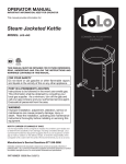
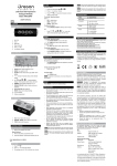
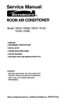
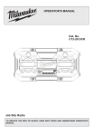
5.0 AIR HANDLER Comfort Control 2 System™
INTERFACE BOARD
FIGURE 8
THE AIR HANDLER CONTROL BOARD EQUIPPED WITH THE Comfort Control2 System™
For the Comfort Control 2 System™, you must have:
• An air handler equipped with the Comfort Control 2 System™
• A condensing unit or heat pump equipped with Comfort Control 2 System™
• A Comfort Control 2 thermostat
If your equipment does not meet this criteria, you must wire it using conventional 24VAC
thermostat control wiring. Reference Section 5.11.
5.1 Comfort Control 2 CONTROL WIRING
The Comfort Control 2 requires four (4) control wires for unit operation:
R – 24VAC
C – 24VAC common
1 – Data wire 1
2 – Data wire 2
Wiring sizing for Comfort Control 2 is identical to systems using low voltage 24V wires.
No t e: Comfort Control 2 requires a minimum 18 AWG.
IMPORTANT: When using Comfort Control 2, do not make any connections to the
24VAC thermostat wires. If any connections are made to the G, W1, W2, Y1, Y2, B, or
ODD wires, the Comfort Control 2 control will assume the control is being used with a traditional thermostat and will IGNORE ANY COMMUNICATIONS USING DATA WIRE 1
AND DATA WIRE 2.
IMPORTANT: Class 2 low voltage control wire should not be run in conduit with power
wiring and must be separated from power wiring, unless Class 1 wire of proper voltage
rating is used.
• The four 18AWG low voltage control wires must be installed from the thermostat to the
indoor unit and from indoor unit to the outdoor unit. The wire length between the thermostat and indoor unit should not be greater than 100 feet. The wire length between
the indoor unit and outdoor unit should not be greater than 125 feet.
• Low voltage control connections are made by extending wires from top of air handler
using wire nuts.
• See wiring diagrams attached to indoor and outdoor sections to be connected.
15
Comfort Control 2 System™ CONTROL WIRING
The RHPL-series of air handlers are designed to operate with conventional 24VAC controls or with a serial communicating system.
• Do not leave excess field control wiring inside unit, pull excess control wire to outside
of unit and provide strain relief for field wiring on inside of cabinet at point wiring penetrates cabinet.
• Make sure, after installation, separation of control wiring and power wiring has been
maintained.
FIGURE 9
TYPICAL The Comfort Control 2 System™ WIRING DIAGRAM
Communicating Thermostat
1
2
R
C
Comfort Control 2 System™ CONTROL WIRING
Indoor Unit
Outdoor Unit
1
1
2
2
R
R
C
C
WIRING INFORMATION
Line Voltage
–Field Installed - - - - - –Factory Standard
5.2 Comfort Control 2 System™ CONTROL BOARD
The RHPL series air handler control, Figure 8, has the following features:
• Memory Card – The memory card stores all information needed for unit operation.
Once the system is wired for serial communications, this information is shared with the
thermostat and outdoor unit. This shared data is available if one of the components in
the system needs to be replaced.
• An automotive-style ATC blade fuse for transformer protection (3 amp).
• An on-board LED to indicate blower CFM.
• An RJ-11 port for use with a diagnostic tool.
• Inputs for field installed supply and return air temperature sensors (available in kit
RXHT-A01)
• DIP switches for airflow adjustments
IMPORTANT: The DIP switches are NOT used when the air handler is wired for serial
communications. Airflow adjustments are performed via the thermostat or a diagnostic
tool.
Installation Verification
• Term and bias dip switches should be on.
• 24V AC power on R&C must be present at the control for the air handler to operate,
reference Figure 9.
• Line voltage must be present at the control for indoor blower operation.
• The RX Data LED will flash green in normal operation. A flashing green light indicates
24VAC is present and the data wires 1 and 2 are wired properly.
IMPORTANT: If the RX DATA LED is solid green, data wire 1 and data wire 2 are not
properly connected. Typically, the connections are switched, i.e. data wire 1 is wired to
the data wire 2 connection and data wire 2 is wired to the data wire 1 connection. Verify
wiring and correct the polarity at the two data wires.
IMPORTANT: Diagnostic port is for the diagnostic tool only. Do not attempt to connect
components using a telephone cord. Damage will occur.
IMPORTANT: Diagnostic port is not a phone jack. Connecting to a telephone or telephone system will result in damage.
5.3 USING THE ON-BOARD LED TO DETERMINE BLOWER CFM
The CFM LED indicates blower output by flashing one (1) flash for every 100 CFM of
airflow. The LED will pause 1/10 second between each flash.
5.4 AIRFLOW ADJUSTMENTS WITH THE Comfort Control 2 System™
The RHPL air handler Comfort Control 2 System™ may operate using the Comfort
Control 2 or via traditional thermostat wiring. When the air handler is wired for the
Comfort Control 2 using Data wire 1 and Data wire 2, the DIP switches on the Comfort
Control 2 control have NO affect on the airflow.
16
serial communicating control have NO affect on the airflow.
IMPORTANT: When using serial communications, the DIP switches have no affect or airf
IMPORTANT:
When using the Comfort Control 2, the DIP switches have no affect on
or on air handler
performance.
airflow or on air handler performance.
5.5 Cooling5.5Airflow
tonnage)
COOLINGSettings
AIRFLOW(by
SETTINGS
(BY TONNAGE)
The RHPL-series of air handlers automatically set cooling airflow when using the
2 System™. The air handler detects the tonnage of the condensing
ComfortofControl
The (-)HPL-series
air handlers
automatically set cooling airflow when using serial
performance and comfort. Refer to Table 2
unit/heat pump and sets airflow for optimum
communications.
The
air
handler
detects
theSelection
tonnage
condensing
unit/heat
pump
for the airflow provided when
the RHPL
air handlerofis the
matched
to the (-)PRL
heat pump.
2 System™ control board does allow the installer to tweak the cool5.7Cooling
Heating
Airflow
Adjustment
The
Comfort Control
5.6
Airflow
Adjustment
2
Comfort Control 2 System™ CONTROL WIRING
and
None
airflow for optimum performance and comfort. Refer to table X.X for the airflow provided
TABLE 1
+10%
the (-)HPL air handler
is matched
to the (-)PRL
heatHEAT
pump.
WHEN MATCHED
TO THE (-)PRL
PUMP
RHPL AIRFLOW
-10%
Airflow
(cfm) Table.
Tonnage
heat Adjustment
Table
X.X of
– Airflow
Selection
nd
st
pump
Stage via 1the
Stage
IMPORTANT: Cooling airflow
adjustment is2accessible
serial communicating
(-)PRL-024JEC
775
625 the cooling airflow
thermostat or via a service
tool. Refer to their instructions
to access
(-)PRL-036JEC
1200
875
adjustment menu.
(-)PRL-048JEC
1625
1200
NOTE: Cooling airflow(-)PRL-060JEC
adjustments are in effect
for cooling operation
1675
1375 only. They are ign
when in heating mode or when electric heat is activated.
Table X.X – (-)HPL airflow when matched to the (-)PRL heat pump.
5.6 COOLING AIRFLOW ADJUSTMENT
ing airflow +/-10% to suit the installation. When using the Comfort Control System™,
the airflow can only be adjusted using the serial communicating thermostat or a service
Theserial
serialcommunicating
communicating
control
does
allow
theadjustment
installerto
totweak
tweak
thecooling
heating
airflow+/-10
+/-10
The
control
allow
the
installer
the
airflow
tool. To adjust the
airflow, does
go
to the
airflow
menu
and select
the desired
adjustment.
(Reference
2.)communications,
suitthe
theinstallation.
installation.
When
usingTable
serial
communications,the
theairflow
airflowcan
canonly
onlybe
beadjusted
adjustedus
u
suit
When
using
serial
theserial
serialcommunicating
communicating
thermostat or a service tool. To adjust the airflow, go to the airflo
the
TABLE 2 thermostat or a service tool. To adjust the airflow, go to the airflow
Selection
adjustmentmenu
menuAIRFLOW
andselect
select
thedesired
desired
adjustment
(referencetable
tableX.X).
X.X).
ADJUSTMENT
SELECTION
TABLE
adjustment
and
the
adjustment
(reference
None
+10%
Selection
-10%
None
+10%
Table X.X – Airflow Adjustment
Selection Table.
-10%
IMPORTANT: Cooling airflow adjustment is
accessible via the serial communicating
thermostat or via a service
tool.
Refer
to
their
instructions
to accessTable.
the cooling airflow
Table X.X – Airflow Adjustment Selection
IMPORTANT:
Cooling
airflow
adjustment
is
accessible
via
the
Comfort
Control 2 theradjustment menu.
mostat or via a service tool. Refer to their instructions to access the cooling airflow
IMPORTANT:
Heating airflow adjustment is accessible via the serial communicating
adjustment menu.
thermostat
orNOTE:
via aairflow
serviceadjustments
tool. Referare
to their
instructions
to access
the heating
airflow
NOTE: Cooling
in effect
for cooling
operation
only. They
are ign
Cooling airflow adjustments are in effect for cooling operation only. They are
adjustment
menu.
when in heating
mode
activated.
ignored
whenor
in when
heatingelectric
mode or heat
whenis
electric
heat is activated.
5.7Airflow
HEATING
AIRFLOW ADJUSTMENT
NOTE:
Heating
airflow Adjustment
adjustments
are in effect for heat pump operation only. They are
5.7 Heating
2 control does allow the installer to tweak the heating airflow +/-10%
The
Control
ignored when
inComfort
cooling
mode
or when electric heat is2activated.
to suit the installation. When using Comfort Control System™, the airflow can only be
2 thermostat
The serial communicating
allow
the installer
to tweak
heating
airflow +/-10
adjusted using thecontrol
Comfortdoes
Control
or a service
tool. Tothe
adjust
the airflow,
go
to
the
airflow
adjustment
menu
and
select the desiredthe
adjustment.
3.)
5.7
Electric
Heat When
Airflow
suit the
installation.
using serial communications,
airflow(Reference
can only Table
be adjusted
u
the serial communicating thermostat or a service tool. To adjust the airflow, go to the airflo
3
The
(-)HPL-series
of air
handlers
are
factory
programmed
to provide
adequate airflow for
adjustment
menuTABLE
and
select
the desired
adjustment
(reference
table X.X).
AIRFLOW
ADJUSTMENT
SELECTION
TABLE
electric heat (auxiliary heat). Airflow for electric heat is fixed and cannot be field adjusted.
Selection
Thermostat
Electric
None Heat Airflow
Input
2-ton
3-ton
4-ton
5-ton
+10%
W1 or W2
800 CFM
1200
CFM
1600
CFM
1800
CFM
-10%
Table X.X – Airflow Adjustment Selection Table.
5.8 Cooling
Mode Dehumidification
IMPORTANT:
Heating airflow adjustment is accessible via the Comfort Control 2 ther-
mostatHeating
or via a service
tool.adjustment
Refer to theirisinstructions
to via
access
heating
airflow
IMPORTANT:
airflow
accessible
thethe
serial
communicating
adjustment menu.
thermostat or via a service tool. Refer to their instructions to access the heating airflow
NOTE: Heating airflow adjustments are in effect for heat pump operation only. They
adjustment menu.
are ignored when in cooling mode or when electric heat is activated.
NOTE: Heating airflow adjustments are in effect for heat pump operation only. They are
17
ignored when in cooling mode or when electric heat is activated.
adjustment menu.
NOTE: Heating airflow adjustments are in effect for heat pump operation only. They are
ignored when in cooling mode or when electric heat is activated.
5.8 ELECTRIC HEAT AIRFLOW
RHPL-series
air handlers are factory programmed to provide adequate airflow for
Electric
Heat of
Airflow
5.7The
electric heat (auxiliary heat). Airflow for electric heat is fixed and cannot be field adjusted.
The (-)HPL-series of air handlers are factory programmed to provide adequate airflow for
TABLE
electric
heat 4(auxiliary heat). Airflow for electric heat is fixed and cannot be field adjusted.
ELECTRIC HEAT AIRFLOW
Thermostat
Input
W1 or W2
ODD TERMINAL
Comfort Control 2 System™ CONTROL WIRING
Electric Heat Airflow
3-ton
4-ton
1200 CFM
1600 CFM
5-ton
1800 CFM
5.85.9
Cooling
Mode
Dehumidification
COOLING
MODE
DEHUMIDIFICATION
TABLE 5
INDOOR
AMBIENT
CONDITION
HIGH HUMIDITY
LOW HUMIDITY
2-ton
800 CFM
INPUT TO “ODD”
TERMINAL
(FROM HUMIDISTAT)
Ø VAC
24 VAC
The serial communicating control is shipped with “On Demand Dehumidification” (ODD)
turned OFF. On Demand Dehumidification may be activated from the serial communicating
thermostat when the serial communicating thermostat has an on-board humidity sensor.
IMPORTANT: On Demand Dehumidification is accessible via the serial communicating
thermostat or via a service tool. Refer to their instructions to access the ODD airflow
4
adjustment menu.
5.10 COOLING DELAY PROFILES
The RHPL air handler is factory configured with optimum ON/OFF delays to maximize
energy efficiency and comfort. In certain situations, the installer may choose an alternate
profile to tweak the system operation for the building load and to maximize comfort. The
alternate profiles are defined below:
IMPORTANT: On Demand Dehumidification, ODD, is the preferred method to maximize
comfort with little or no loss of energy efficiency. If using ODD, do NOT use any of the
alternate profiles. Only use the factory default profile. Use of the alternate profiles with
ODD will decrease energy efficiency with no gain in comfort.
Profile A – Factory default profile.
Air Handler
RHPL-HM2421
RHPL-HM3621
RHPL-HM4824
RHPL-HM6024
On Delay
Delay Duration
% Rated Airflow
(second)
No Delay
N/A
No Delay
N/A
No Delay
N/A
No Delay
N/A
Off Delay (seconds)
45
45
45
45
Profile B – Quiet Start profile
The Quiet Start profile is configured to bring the blower up to 50% airflow for 30 seconds
before advancing to 100% airflow. This helps to minimize the blower noise at system
startup.
Air Handler
RHPL-HM2421
RHPL-HM3621
RHPL-HM4824
RHPL-HM6024
On Delay
Delay Duration
% Rated Airflow
(second)
30
50
30
50
30
50
30
50
Off Delay (seconds)
15
15
15
15
Profile C – Humid profile
The humid profile is configured to run the blower at 80% airflow for about the first four
minutes of system operation to remove more moisture from the conditioned space.
Air Handler
RHPL-HM2421
RHPL-HM3621
RHPL-HM4824
RHPL-HM6024
On Delay
Delay Duration
% Rated Airflow
(second)
255
80
255
80
255
80
255
80
Off Delay (seconds)
0
0
0
0
Profile D – Dry Climate profile
The Dry Climate profile is configured for areas that require little to no additional dehumidification.
Air Handler
RHPL-HM2421
RHPL-HM3621
RHPL-HM4824
RHPL-HM6024
18
On Delay
Delay Duration
% Rated Airflow
(second)
150
88
150
88
150
88
150
88
Off Delay (seconds)
60
60
60
60
WIRE COLOR CODE
BK – BLACK G – GREEN
BR – BROWN GY – GRAY
R – RED
PR – PURPLE Y – YELLOW
BL – BLUE
W – WHITE
O – ORANGE
FIGURE 10
FIGURE 11
TYPICAL 2-STAGE THERMOSTAT: HEAT PUMP WITH ELECTRIC
HEAT
TYPICAL TWO-STAGE THERMOSTAT: (-)PRL HEAT PUMP WITH
ELECTRIC HEAT USING A HUMIDISTAT FOR DEHUMIDIFICATION*.
Typical Two-Stage Thermostat
B Y1 Y2 G
E/W1
Typical Two-Stage Thermostat
R
W2 C
B Y1 Y2 G
E/W1
W2 C
R
Humidistat
(-)HPL Air
Handler
(-)HPL Air
Handler
(-)PRL
Heat Pump
Outdoor
Unit
W1
W2
W2
Y
Y1
Y/BL
B
BL
Y1
Y
Y1
Y2
Y/BL
Y2
B
BL
B
R
R
R
Y1
Y2
B
R
R
R
C
BR
C
G
W/R
ODD
PR
L
D
WIRING INFORMATION
Line Voltage
-Field Installed
-Factory Standard
C
BR
C
G
W/R
L
ODD
PR
D
CONVENTIONAL THERMOSTAT WIRING
Y2
(-)PRL
Heat Pump
Outdoor
Unit
W1
WIRING INFORMATION
Line Voltage
-Field Installed
-Factory Standard
*See Section 5.17 for proper DIP switch selection.
S8
S7
S6
S5
S4
S3
S2
S8
S7
S5
S1
S6
OFF
S4
OFF
S3
ON
S2
ON
S1
DIP SWITCH POSITIONS
DIP SWITCH POSITIONS
FIGURE 13
FIGURE 12
TYPICAL TWO-STAGE THERMOSTAT: (-)PRL HEAT PUMP WITH
ELECTRIC HEAT USING A TWO-STAGE THERMOSTAT WITH
DEHUMIDIFICATION*
(-)PRL HEAT PUMP WITH ELECTRIC HEAT USING A TWO-STAGE
THERMOSTAT WITH DEHUMIDIFICATION* AND A MALFUNCTION
LIGHT
Typical Two-Stage Thermostat
Typical Two-Stage Thermostat
B Y1 Y2 G
E/W1
W2 C
B Y1 Y2 G
R DHM
E/W1
W2 C
R DHM
L
(-)HPL Air
Handler
(-)HPL Air
Handler
(-)PRL
Heat Pump
Outdoor
Unit
W1
W2
Y1
Y
Y2
Y/BL
B
BL
Y1
Y2
B
R
R
C
BR
C
G
W/R
L
ODD
PR
D
R
(-)PRL
Heat Pump
Outdoor
Unit
W1
W2
Y1
Y
Y1
Y2
Y/BL
Y2
B
BL
B
R
R
R
C
BR
C
G
W/R
L
ODD
PR
D
WIRING INFORMATION
Line Voltage
- Field Installed
- Factory Standard
WIRING INFORMATION
Line Voltage
- Field Installed
- Factory Standard
*See Section 5.17 for proper DIP switch selection.
*See Section 5.17 for proper DIP switch selection.
DIP SWITCH POSITIONS
DIP SWITCH POSITIONS
ON
S8
S7
S6
S5
S4
S3
S2
S8
S7
S6
S5
S4
S3
S2
S1
OFF
OFF
S1
ON
19
5.11 CONVENTIONAL 24VAC THERMOSTAT CONTROL WIRING
The (-)PRL series of heat pumps allow the installer to use conventional 24VAC control
wiring and a conventional thermostat for proper unit operation.
IMPORTANT: The preferred method of unit installation and operation is by the Comfort
6.2 Serial Communications
Control
access to the fault history of the system. This diagnosControl System™, which allows
2
tic information is not available when the (-)PRL unit is using a conventional thermostat.
Reference section 5.1 Comfort Control 2 System™ Control Wiring.
The (-)HPL series
air handler
control,
figure
X.X,of has
following
control wiring
requires
a minimum
eight the
(8) wires
for properfeatures:
unit operation:
Thermostat
R – 24VAC
C – ATC
24VACblade
common
An automotive-style
fuse for transformer protection (3 amp).
G – Constant Fan
An on-board LEDW1
to –indicate
CFM.
First stageblower
electric heat
Second
electric heat
An RJ-11 port for W2
use– with
a stage
diagnostic
tool.
Y1 – First stage operation
Inputs for field installed
supply
return air temperature sensors (available in kit RXH
Y2 – Second
stageand
operation
B
–
Heat
pump
operation
A01)
Optional
wiring: adjustments
• DIP switches
for airflow
•
•
•
•
ODD – On demand humidification
IMPORTANT:
Aelectric
diagnostic
tool can be used to display any air handler diagnostic code
call for
heat is received.
However, no system
changes
are permitted.
Anywiring,
system
changes
MUST control
be done via the
NOTE: When
using 24VAC
thermostat control
the serial
communicating
will
ignore
any
inputs
to
Data
wire
1
and
Data
wire
2.
switches.
CONVENTIONAL THERMOSTAT WIRING
NOTE: W1 and W2 may be jumpered together to energize all the electric heat when a
IMPORTANT: Class 2 low voltage control wire should not be run in conduit with power
wiring and must be separated from power wiring, unless Class 1 wire of proper voltage
Verification
rating is used.
Installation
Low voltage
control must
wiring should
be 18 AWG
color-coded
minimum).
For to operate
24V AC power
on R&C
be present
at the
control(105°C
for the
air handler
lengths longer than 100 ft., 16 AWG wire should be used.
Line voltage must be present at the control for indoor blower operation.
Low voltage control connections are made by extending wires from top of air handler
The control
wires
must be connected to a conventional 24VAC thermostat for proper
using
wire nuts.
operation.See wiring diagrams attached to indoor and outdoor sections to be connected
•
•
•
Do not leave excess field control wiring inside unit, pull excess control wire to outside of
unit and provide strain relief for field wiring on inside of cabinet at point wiring penetrates
cabinet.
6.3 Using the On-Board LED to Determine Blower CFM
Make sure, after installation, separation of control wiring and power wiring has been
maintained.board LED indicates blower output by flashing one (1)
interface
The (-)HPL
second for e
100 CFM of airflow. The LED will pause 1/10 second between each flash. After the blo
USING THE
LED TO DETERMINE
CFM before repeating
CFM has been5.12
displayed,
the ON-BOARD
LED will illuminate
dimly forBLOWER
10 seconds
The CFM LED indicates blower output by flashing one (1) flash for every 100 CFM of airsequence. (See
Table
1.) will pause 1/10 second between each flash.
flow.
The LED
5.13 COOLING AIRFLOW SETTINGS
6.4 Cooling Airflow
FIGURE 14 Settings
DIP SWITCH SETTING FOR COOLING AIRFLOW
Figure X – DIP switch setting for cooling airflow
20
The RHPL-series of air handlers are factory configured to for proper airflow. The cooling
The (-)HPL-series
of air
handlers
are
factory
configured
to effect
for proper
airflow.
The cooling
airflow (CAF)
is fixed
and the
DIP
switch settings
have no
on airflow.
The factory
setting
is:
airflow (CAF) is fixed and the DIP switch settings have no effect on airflow. The factory
The (-)HPL-series of air handlers are factory configured to for proper airflow. The cooling
is:
TABLE
6
airflow (CAF)
is fixed
and the DIP switch settings
have no
effect on airflow. The factory setti
Airflow
24VAC THERMOSTAT
AIRFLOW SETTINGS WHEN USING TRADITIONALCooling
is:
2-ton
3-ton
4-ton
5-ton
Cooling Airflow
Y1
Y2
Y1
Y2
Y1
Y2
Y1
Y2
2-ton
3-ton
4-ton
5-ton
CFM
625
775
900 1200 1200 1625 1375 1675
Y1
Y2
Y1
Y2
Y1
Y2
Y1
Y2
CFM
625
775
900
1200
1200
1625
1375
1675
Table X.X – Airflow settings when using traditional 24VAC thermostat
TableThe
X.XDIP
– Airflow
settings
whenonly
usingwhen
traditional
thermostat
IMPORTANT:
switches
are active
using 24VAC
conventional
a 24VAC
IMPORTANT: The DIP switches are active only when using conventional a 24VAC therthermostat.
If using
serial
communications,
refer
to section
5conventional
for adjusting
2 System™,
refer
to Section
5.13 for adjusting
airIf using
Comfortare
Control
mostat.
IMPORTANT:
The
DIPthe
switches
active
only when
using
a airflows.
24VAC
flows.
thermostat. If using serial communications, refer to section 5 for adjusting airflows.
6.5 Heating
Airflow
Adjustment
FIGURE
15
DIP SWITCH SETTING FOR HEAT PUMP AIRFLOW
6.5 Heating
Airflow Adjustment
CONVENTIONAL THERMOSTAT WIRING
Figure
X – DIP
switch setting for heat pump airflow
5.14 HEATING
AIRFLOW
ADJUSTMENT
Figure X – DIP switch setting for heat pump airflow
The RHPL-series of air handlers are factory configured to for proper airflow. The heat
pump airflow
(PAF)
is fixed are
and the
DIP switch
settings to
have
effect on
airflow. The
The (-)HPL-series
of air
handlers
factory
configured
fornoproper
airflow.
The heat pu
The (-)HPL-series
of airis:handlers are factory configured to for proper airflow. The heat pump
factory setting
airflow
and the
theDIP
DIPswitch
switchsettings
settingshave
have
effect
airflow.
factory
airflow (PAF)
(PAF) is
is fixed
fixed and
nono
effect
onon
airflow.
TheThe
factory
settis
is:
TABLE 7
is:
AIRFLOW SETTINGS WHEN USING TRADITIONAL 24VAC THERMOSTAT
HeatingAirflow
Airflow
Heating
2-ton
3-ton
4-ton
5-ton
2-ton
3-ton
4-ton
5-ton
Y1 Y2
Y2 Y1
Y1 Y2
Y2 Y1Y1 Y2Y2 Y1Y1 Y2 Y2
Y1
CFM
625
775
900
1200
1200 1625
16251375
13751675
1675
625
775
900
1200
1200
CFM
Table
X.X –– Airflow
Airflowsettings
settingswhen
whenusing
usingtraditional
traditional
24VAC
thermostat
24VAC
thermostat
Table X.X
IMPORTANT: The DIP switches are active only when using conventional a 24VAC ther-
2 System™,
IMPORTANT:
DIP
switches
only
conventional
a 24VAC
IMPORTANT:
DIP
switches
areactive
active
onlywhen
when
using
conventional
a 24VAC
referusing
to
Section
5.14 for adjusting
airmostat. The
If using
the
Comfort are
Control
flows.
thermostat. If
If using
5 for
adjusting
airflows.
thermostat.
serial communications,
communications,refer
refertotosection
section
5 for
adjusting
airflows.
using serial
FIGURE 16
6.6Airflow
Airflow
Adjustment
(TRIM)
DIPAdjustment
SWITCH SETTING FOR
AIRFLOW ADJUSTMENTS
6.6
(TRIM)
Figure X – DIP switch setting for airflow adjustments
21
5.15 AIRFLOW ADJUSTMENT (TRIM)
Figure
X – DIP
switch
setting
for
airflow
Figure
Xcan
– DIP
setting
for airflow
Cooling and heat pump
airflow
be switch
adjusted
+/-10%
to adjustments
suitadjustments
the installation. To adjust
the airflow, set DIP switches 5 & 6 per Table 8:
Cooling
and
pump
airflow
can be
+/-10%
to suit
To adjust
the the
Cooling
and heat
pump
airflow
canadjusted
be adjusted
+/-10%
to the
suitinstallation.
the installation.
To adjust
TABLE
8 heat
airflow,
set
DIP
switches
5 & 56 &
per6TABLE
Table
X.X:X.X:
airflow,
set DIP
switches
per Table
AIRFLOW
ADJUSTMENT
SELECTION
Airflow
Adjustments
Airflow
Adjustments
2-ton2-ton
3-ton3-ton
4-ton4-ton
5-ton5-ton
Position
Switch
Switch
SwitchY1 Y1Y2 Y2Y1 Y1Y2 Y2Y1 Y1Y2 Y2Y1 Y1Y2 Y2
Position
Switch
5 5 6 6
A A OFFOFF OFFOFF625 625775 775900 900
12001200
12001200
16251625
13751375
16751675
B B ON ON OFFOFF700 700850 850
10001000
13251325
13251325
18001800
15251525
18501850
C C OFFOFF ON ON 575 575700 700800 800
10751075
10751075
14751475
12501250
15001500
D D ON ON ON ON 625 625775 775900 900
12001200
12001200
16251625
13751375
16751675
Table
X.X X.X
– Airflow
Adjustment
Selection
Table.
Table
– Airflow
Adjustment
Selection
Table.
IMPORTANT: The DIP switches are active only when using conventional a 24VAC ther2 System™,
IMPORTANT:
The Comfort
DIP DIP
switches
are active
onlyonly
when
using
conventional
24VAC
mostat.
If using the
Control
refer
tousing
Section
5.15a for
IMPORTANT:
The
switches
are active
when
conventional
aadjusting
24VAC airthermostat.
If using
serialserial
communications,
referrefer
to section
5 for5adjusting
airflows.
flows.
thermostat.
If using
communications,
to section
for adjusting
airflows.
NOTE: Airflow adjustment is active for cooling and heat pump operation only. They are
NOTE:
Airflow adjustment
is active
for cooling
and heat
pump
operation
only.only.
TheyThey
are are
NOTE:
is active
for cooling
and heat
pump
operation
ignored
whenAirflow
electricadjustment
heat is activated.
ignored
whenwhen
electric
heat heat
is activated.
ignored
electric
is activated.
CONVENTIONAL THERMOSTAT WIRING
DIP DIP
Switch
Settings
Switch
Settings
5.16
ELECTRIC
HEAT
AIRFLOW
6.7 Electric
Heat
Airflow
6.7
Electric
Heat
Airflow
The RHPL-series of air handlers are factory programmed to provide adequate airflow for
The The
(-)HPL-series
of airof
handlers
are factory
programmed
provide
adequate
airflow
for
(-)HPL-series
air handlers
are
programmed
to and
provide
adequate
airflow
for
electric
heat
(auxiliary
heat).
Airflow
forfactory
electric
heat istofixed
cannot
be
field
adjustelectric
heat heat
(auxiliary
heat).heat).
Airflow
for electric
heat heat
is fixed
and cannot
be field
adjusted.
electric
(auxiliary
Airflow
for electric
is fixed
and cannot
be field
adjusted.
ed.
Thermostat
Electric
HeatHeat
Airflow
Thermostat
Electric
Airflow
InputInput
2-ton2-ton
3-ton3-ton
4-ton4-ton
5-ton5-ton
W1 or
CFMCFM 16001600
CFMCFM 18001800
CFMCFM
W1W2
or W2 800 CFM
800 CFM 12001200
6.8 Cooling
Mode
Dehumidification
5.17
COOLING
MODE
DEHUMIDIFICATION
6.8
Cooling
Mode
Dehumidification
FIGURE 17
ON DEMAND DEHUMIDIFICATION DIP SWITCH
10 10
Figure
Figure X
X –– On
On Demand
Demand Dehumidification
Dehumidification DIP
DIP Switch
Switch
The
handler
shipped
with
“On
(ODD)
The (-)HPL-series
(-)HPL-series air
airFigure
handler
shipped
withDehumidification
“On Demand
Demand Dehumidification”
Dehumidification”
(ODD) turned
turned
X is
–is On
Demand
DIP Switch
The
air handler is shipped
“On Demand
(ODD)
OFF.
On
is
in
with
aa traditional
thermostat
OFF.RHPL-series
On Demand
Demand Dehumidification
Dehumidification
is used
usedwith
in conjunction
conjunction
withDehumidification”
traditional 24VAC
24VAC
thermostat
turned
OFF.
Demand
Dehumidification
is Demand
usedODD
in conjunction
withswitch
a(ODD)
traditional
The
(-)HPL-series
air
handler
is shipped
with “On
Dehumidification”
turned
equipped
with
an
humidity
sensor.
Activate
by
77 ON.
When
equipped
withOn
an on-board
on-board
humidity
sensor.
Activate
ODD
by turning
turning DIP
DIP
switch
ON.
When
24VAC
thermostat
equipped
with
anused
on-board
humidity
sensor.
Activate
ODD
by turnOFF.
On
Demand
Dehumidification
is
in
conjunction
with
a
traditional
24VAC
thermostat
ODD
is
turned
ON,
the
thermostat
sends
a
24VAC
signal
to
the
ODD
input
of
the
air
handler.
ODD is turned ON, the thermostat sends a 24VAC signal to the ODD input of the air handler.
ing DIP switch
7 ON. ODD operation is controlled by the indoor humidity sensed at the
equipped
with
Operation
is:
Operation
is: an on-board humidity sensor. Activate ODD by turning DIP switch 7 ON. When
thermostat.
is:
ODD
is turnedOperation
ON, the thermostat
sends a 24VAC signal to the ODD input of the air handler.
Operation
is:
Normal
(humidity
set
point):
Normal
Humidity
(humidityBELOW
BELOWthe
thethermostat
thermostat
point):
Normal Humidity
Humidity
(humidity
BELOW
the
thermostat
setset
point):
Normal Humidity (humidity
BELOW
the thermostat set point):Result
Normal
Humidity
Normal
Humidity
Result
A
Full
A 24VAC
24VAC signal
signal is
is applied
applied to
to
Full rated
rated airflow
airflow is
is delivered
delivered
Normal
Humidity
Result
the
terminal
by
the ODD
ODD
terminal
by the
the blower
blower
A 24VAC signal is applied to
Full rated airflow is delivered
ODD terminal
byset
the
blower
High
(humidity
ABOVE
point):
High Humidity
Humiditythe
(humidity
ABOVEthe
thethermostat
thermostat
set
point):
(humidity
ABOVE
the
thermostat
set
point):
22
High Humidity (humidityHigh
ABOVE
the thermostat set point): Result
Humidity
High
Humidity
Result
No
Airflow
No signal
signal applied
applied to
to the
the ODD
ODD
Airflow is
is reduced
reduced by
by aa preset
preset
Result latent
terminal
amount
terminalHigh Humidity
amount to
to increase
increase
latent
No signal applied to the ODD
Airflow
capacity
capacityis reduced by a preset
terminal
amount to increase latent
capacity
The
to
maximum
efficiency
and
humidity
The
RHPL air
air
handler
programmed
to
provide
maximum
efficiency
and optimum
The (-)HPL
(-)HPL
air handler
handler is
isisprogrammed
programmed
to provide
provide
maximum
efficiency
and optimum
optimum
humidity
removal.
humidity
detected,
the
air
reduces
cooling
airflow
humidity
removal.
highis
the
air handler
cooling
airremoval. When
When high
highWhen
humidity
ishumidity
detected,is
thedetected,
air handler
handler
reduces
coolingreduces
airflow defined
defined in
in
The
(-)HPL
Table
X.X.
flow
defined
Tableis9.programmed to provide maximum efficiency and optimum humidity
Table
X.X. airinhandler
removal. When high humidity is detected, the air handler reduces cooling airflow defined in
Table X.X.
Air
Cooling
Air Handler
Handler
Cooling Airflow
Airflow
Reduction
Reduction
Air Handler
Cooling
Airflow
2-ton
85%
2-ton
85%
Reduction
3-ton
terminal
amount to increase latent
capacity
The (-)HPL air handler is programmed to provide maximum efficiency and optimum humidity
removal.
high humidity is detected, the air handler reduces cooling airflow defined in
TABLE When
9
ODD AIRFLOW
REDUCTION
Table
X.X.
Air Handler
Cooling Airflow
Reduction
85%
2-ton
3-ton
4-ton
5-ton
80%
Table X.X – ODD Airflow Reduction
IMPORTANT: The DIP switches are active only when using conventional a 24VAC therIMPORTANT: The DIP switches are2active only when using conventional a 24VAC
mostat. If using the Comfort Control System™, refer to Section 5.17 for adjusting airflows.
thermostat. If using serial communications, refer to section 5 for adjusting airflows.
(Refer to Section 5.9.)
NOTE: ODD airflow adjustments are active for cooling operation only. They are
ignored when the heat pump is in heating mode or when electric heat is activated.
11
TABLE 10
SELECTION C EXPLANATION: ON DEMAND DEHUMIDIFICATION
SWITCH 7
POSITION
ODD
INPUT
ON
NONE
24VAC
3-TON
4-TON
5-TON
Y1
Y2
Y1
Y2
Y1
Y2
Y1
Y2
500
625
625
775
725
900
950
1200
950
1200
1300
1625
1100
1375
1350
1675
5.18 COOLING DELAY PROFILES
Cooling delay profiles are not available when the RHPL air handler is controlled using a
conventional 24VAC thermostat. These profiles are available only when the air handler
is wired for the Comfort Control 2 System™. Refer to Section 5.10 for Comfort Control 2
Cooling Delay Profiles wiring.
5.19 AIR HANDLER DIAGNOSTIC CODES
Descriptions of the air handler Comfort Control 2 diagnostic codes are provided below.
These codes can be displayed at the thermostat or via a diagnostic tool.
IMPORTANT: Air handler diagnostic codes are available at the thermostat when the
system is wired for Comfort Control 2.
23
CONVENTIONAL THERMOSTAT WIRING
COOLING AIRFLOW - CFM
2-TON
Descriptions
of the
the air
air handler
handler serial
serial communicating
communicating control
control diagnostic
diagnostic codes
codes are
are provided
provided
Descriptions of
Thesecodes
codescan
canbe
bedisplayed
displayedatatthe
thethermostat
thermostator
orvia
viaaadiagnostic
diagnostictool.
tool.
below. These
below.
X.X Air Handler Diagnostic Codes
7-Segment
Status/Possible
Cause
– Troubleshooting
LEDs Display
AIR
HANDLER
IMPORTANT:
Air
diagnostic
codes
are
at
the
the
system
IMPORTANT:
Air
handler
diagnostic
codesDIAGNOSTIC
are available
available
atCODES
the thermostat
thermostat
when
the
system isis
Descriptions
of the
airhandler
handler
serial
communicating
control
codeswhen
are
provided
Code
Descriptions
of the
ICC
diagnostic codes
arediagnostic
provided below:
Diagnostic
Description
Information
wired
for
serial
communications.
If
wired
serialcodes
communications.
If at the thermostat or via a diagnostic tool.
below.for
These
can be displayed
d1 – No SharedCodes
Data
X.X Air Handler Diagnostic
CONVENTIONAL THERMOSTAT WIRING
• Replace memory card with correct system
The control board does not have shared
information
7-Segment
7-Segment
7-Segment
7-Segment
data.
Status/Possible
Cause
– Troubleshooting
Troubleshooting
IMPORTANT:
Airair
handler
diagnostic
codes are available
atdiagnostic
the thermostat
when
the system is
Status/Possible
Cause
LEDs
Display
Descriptions
handler
serial
communicating
control
codes
provided
LEDsDisplay
Display of the
Diagnostic
Description
Status/Possible
Cause
–are
LEDs
Status/Possible
Cause
––Troubleshooting
Troubleshooting
LEDs
Display
Information
Code
wired
for
serial
communications.
If
d3Diagnostic
– Airflow
CFM
Code
Diagnostic
Description
Information
Misapplied/wrong
Code
Description
Information
Code
Information
Diagnostic
Description
below.
These codes can
be
displayed
atMismatch
the thermostat or via a• diagnostic
tool. indoor air mover – replace
The
air handler
cannot supply the required
with
properly
sized air handler/furnace.
d1
–
No
Shared
Data
d1
–
No
Shared
Data
d1
–
No
Shared
Data
d1 – No Shared Data
• Replace memory card with
system
airflow
for
proper
system
operation
ELECTRONICScorrect
GROUP
TO
ELECTRONICS
GROUP
TO
7-Segment
The
control
board
does
not
have
shared
data.
information
IMPORTANT: Air handler diagnostic codes are available at the thermostat when the system is
Status/Possible
Cause card
– Troubleshooting
LEDs Display
DESCRIBE
d4 – (Device) If
Memory Card Invalid for
• CheckDESCRIBE
memory
to ensure it matches
wired
for serial communications.
Code
Diagnostic
Description
Information
7-Segment
Device
device
d3
Airflow
CFM
Mismatch
Misapplied/wrong
indoor
air
mover
replace
d3
Airflow
CFM
Mismatch
7-Segment
•••• Misapplied/wrong
indoor
air
mover
–––replace
d3–
Airflow
CFM
Misapplied/wrong
indoor
mover
– replace
d3
Airflow
CFM
Mismatch
Misapplied/wrong
indoor
air
mover
replace
d1
––––No
Shared
Data
Status/Possible
Cause
– air
Troubleshooting
LEDs
Display
The
data
inMismatch
the memory card inserted into
The
indoor
air
mover
(air
handler/furnace)
air
handler
cannot
supply
the
required
properly
sized
air
handler/furnace.
The
with
with
properly
sized
air
handler/furnace.
The
indoor
air
mover
(air
handler/furnace)
7-Segment
Status/Possible
Cause
–
Troubleshooting
LEDs
Display
with
properly
sized
air
handler/furnace.
The
indoor
air
mover
(air
handler/furnace)
ELECTRONICS
GROUP
with properly Information
sized air handler/furnace.TO
Code
Diagnostic
Description
the
control
board
does not match the data in
airflowsupply
for Diagnostic
proper
system
operation
cannot
supply
the
required
airflow
for
the
required
airflow
for
Status/Possible
Cause
Troubleshooting
LEDs
Display d1cannot
Code
Description
Information
cannot
supply
the
required
airflow
for
– No Shared
Data
• Replace memory
card
with –correct
system
the control.
DESCRIBE
proper
system
operation
proper
system
operation
Code
Information
Diagnostic
Description
d1
–
No
Shared
Data
proper
system
operation
•
Replace
memory
card
with
correct
system
The
control
board
does
not
have
shared
information
d5
–
Card
Hardware
Conflict
•
Replace
the
air
handler
motor
with the correct
X.X
Air Handler
Diagnostic
Codes
7-Segment
Check memory card indoor
to ensure
itmover
matches– replace
–control
(Device)
Memory
Card
Invalid
forfor
• Misapplied/wrong
d4–––
d4
(Device)
Memory
Card
Invalid
for
•
d4
(Device)
Memory
Card
Invalid
d1
No
Shared
Data
The
board
does
not
have
shared
•
d3
Airflow
CFM
Mismatch
d4
(Device)
Memory
Card
Invalid
for
information
air
•
data.
The
motor
horsepower
is
not
correct
for
the
horsepower
motor.
Device
device
Status/Possible
Cause
–GROUP
Troubleshooting
LEDs Display Device
Device
ELECTRONICS
TO
data.
The
indoor
aircard
mover
(air handler/furnace)
Device
with
properly
sized
air
handler/furnace.
The
memory
is missing
or the data in the
air CFM
handler
• Check• ifReplace
memory card
is present
the
memory
card –with
correct system
d3
–
Airflow
Mismatch
Code
Diagnostic
Description
Information
•
Misapplied/wrong
indoor
air
mover
replace
Descriptions of cannot
the
airsupply
handler
serial
communicating
control diagnostic
codes
are
provided
the required
airflow
memory
card does
not
match
the data for
in the
DESCRIBE
information.
d3
––Airflow
CFM
Mismatch
•with
indoor
aircorrect
mover system
– replace
air
handler
cannot
supplyatthe
required
properly
sized air
handler/furnace.
d1
No
Shared
Data
• Misapplied/wrong
Replace
memory
card
with
control.
proper
system
operation
below.
TheseThe
codes
can
be
displayed
the
thermostat
or
via
a• diagnostic
tool.
7-Segment
7-Segment
The
air
handler
cannot
supply
the
required
d8
–
Old
Shared
Data
with
properly
sized
air
handler/furnace.
If
system
will
not
operate,
order
new memory
for proper
system
operation
The
control
board
does
not have
shared
information
7-Segment airflow
d3
Airflow
CFM
Mismatch
indoor
mover
– replace
d5–––(Device)
Card
Hardware
Conflict
Replace
the air handler
motor
with
the correct
Memory
Card
Invalid
for
•••• Misapplied/wrong
Status/Possible
Cause
–– air
Troubleshooting
LEDs
Status/Possible
Cause
Troubleshooting
LEDs Display
Display d4
airflow
for
proper
system
operation
System
data
is
obsolete
card
to
update
system
information.
data.indoor
horsepower
motor.
The
air
moverCard
(air
Status/Possible
Cause
– Troubleshooting
LEDs
Display d4Device
motor Diagnostic
horsepower
is
nothandler/furnace)
correct for
the
with
properly
sized
air
handler/furnace.
–The
(Device)
Memory
Invalid
forare
Code
Information
Description
• Check
card
tocard
ensure
matches
Code
Diagnostic
Description
Information
IMPORTANT:
Air
handler
diagnostic
codes
available
atmemory
the
when
the system
system is
• Replace
thethermostat
memory
with it
correct
air
handler
Code
cannot
supply
the
required
airflow
for
Diagnostic
Description
Information
d4
–
(Device)
Memory
Card
Invalid
for
•
Check
memory
card
to
ensure
it matches
Device
d1
–
No
Shared
Data
device
d3
–
Airflow
CFM
Mismatch
•
Replace
memory
card
with
correct
system
•
Misapplied/wrong
indoor
air
mover
– replace
information.
d1
–
No
Shared
Data
•
Replace
memory
card
with
correct
system
wired for serial
communications.
If
proper
system
operation
d1
–control
No
Shared
Data
• information
Replace
memory
card
with
correct
system
Device
device
The
data
in
the
memory
card
inserted
into
68
–
ECM
No
Signal
The
board
does
not
have
shared
The
air
handler
cannot
supply
the
required
•
Make
sure
the
ECM
motor
wiring
harness
with
properly
sized
air
handler/furnace.
The
control
board
does not have shared
information
d6 ––data
BLWR
HP
CNFLCT
Replace the motor with correct horsepower
d4
(Device)
Memory
Card
Invalid
for
control
board
does
not
have
shared
•• information
The
in the
memory
card
inserted
into
•••to
thedata.
control
board
does
not
match
the
data
in
The
ECM
motor
is
not
communicating
airflow
for
proper
system
operation
plugged
into
the
ECM
motor
and
control
data.
Blower Horsepower conflict
motor.
Device
data.
7-Segment thethe
control
does
not
match
the
control.
the board
air handler
control
board.
The
horsepower
data
in the
memory
carddata in
• Replace board.
the memory card with correct system
d3
–
Airflow
CFM
Mismatch
d4
–
(Device)
Memory
Card
Invalid
for
•
Misapplied/wrong
indoor
mover
– replace
•
Check
memory
card
to ensure
it ensure
matches
Status/Possible
Cause
–air
Troubleshooting
LEDs Display d5the
d3
–control.
Airflow
CFM
Mismatch
Misapplied/wrong
indoor
air
mover
replace
notHardware
matchCFM
the motor
horsepower.
information.
memory
card
to
–does
Card
Conflict
• ••Replace
the
airCheck
handler
motor
with
the ––correct
•
Test
the
ECM
motor
for
proper
operation using
d3
–
Airflow
Mismatch
Misapplied/wrong
indoor
air
mover
replace
The
air
handler
cannot
supply
the
required
Device
with
properly
sized
air
handler/furnace.
device
it
matches
device
Code
The
air
handler
cannot
supply
the required
Diagnostic
Description
Information
with
properly
sized
air
handler/furnace.
d5
–
Card
Hardware
Conflict
•
Replace
the
air
handler
motor
with
the
correct
The
motor
horsepower
is
not
correct
for
the
horsepower
motor.
a
service
tool.
The
air
handler
cannot
supply
the
required
with
properly
sized
air
handler/furnace.
30
Fuse
Open
•• The
The3-amp
3-amp
fuse
onthe
theICC
ICC
is
open.system
airflow
for
proper
system
operation
30
––––motor
Fuse
Open
The
data
in
the
memory
card
insertedfor
into
fuse
on
open.
30
Fuse
Open
The
3-amp
fuse
on
the
ICC
open.
airflow
for
proper
system
operation
d1
No
Shared
Data
isSensor
not
correct
the • •••Replace
horsepower
motor.
d7
BLWER
MFG
CNFLCT
Replace
thememory
memory
card
withisis
correct
airThe
handler
the
with
correct
system
81
–horsepower
Return
Air
Out
of
Range
airflow
for
proper
system
operation
•voltage
Make
sure card
the
sensor
is is
plugged
intoorthe air
The
ICC
detects
the
on-board
fuse
is
open
The
ICC
detects
the
on-board
fuse
is
open
the
control
board
does
not
match
the
data
in
•
Low
wiring
at
R
and
C
damaged
The
ICC
detects
the
on-board
fuse
is
open
•
Low
voltage
wiring
at
R
and
C
damaged
or
The
System
does
not
have
any
data
on
the
information.
ELECTRONICS
GROUP
TO
•
Low
voltage
wiring
at
R
and
C
ismatches
damaged
or
air –handler
Replace
the memory
card
withititis
correct
system
d4
(Device)
Memory
Card
Invalid
for
•
Check
memory
card
to
ensure
information.
The
resistance
of
the
sensor
out
of
range
for
handler
control
board.
d4
–
(Device)
Memory
Card
Invalid
for
•
Check
memory
card
to
ensure
matches
installed
motor.Memory Card Invalid for
the
control.
miswired.
miswired.
d4
–
(Device)
miswired.
•
Check
memory
card
to
ensure
it
matches
information.
device
DESCRIBE
normalData
operation.
d8Device
–d5Old
Shared
• If• system
not
operate,
order
Device
• will
Check
the
resistance
ofnew
the memory
sensor.
Replace if
device
–Old
Card
Hardware
Conflict
Replace
the
air
handler
motor
correct
Device
device
d8
–
Shared
Data
•
If
system
will
not
operate,
orderwith
newthe
memory
The
data
in
the
memory
card
inserted
into
System
data
is
obsolete
card
to
update
system
information.
The
data
in
the
memory
card
inserted
into
it
is
out
of
tolerance.
•
•
The
motor
horsepower
is
notinserted
correct for
30
Fuse
Open
motor.
d8––control
–data
Old
Shared
Data
Ifhorsepower
system
will
not
operate,
order
new
memory
d3
Airflow
Mismatch
•••• The
3-amp
fuse
on
the
ICC
is mover
open.
The
in
the
memory
card
intothe
Misapplied/wrong
indoor
air
– replace
System
data
isCFM
obsolete
card
to
update
system
information.
the
does
not
match
the
data
in
the
control
board
does
not
match
the
data
in
82
–board
Air
Sensor
Out
of
Range
• update
Make
sure
the
sensor
isisplugged
into
System
data
isSupply
obsolete
card
to
system
information.
air
handler
The
ICC
detects
the
on-board
fuse
is
open
The
indoor
air
mover
(air
handler/furnace)
•
Replace
the
memory
card
with
correct
system
the
control
board
does
not
match
the
data
in
with
properly
sized
air
handler/furnace.
•
Low
voltage
wiring
at
R
and
C
damaged
orthe air
the
the control.
control.
The
resistance
of
the
sensor
out
of
range
for
handler
control
board.
cannot
supply
the required
airflow for
information.
the
miswired.
68d5
– ECM
No
Signal
• ••Make
sure the
the
ECM
motormotor
wiring
harness
––control.
Card
Hardware
Conflict
Replace
air
handler
the
d5
Card
Hardware
Conflict
normal
operation.
Replace
thethe
airECM
handler
motor
with
the correct
correct
•sure
Check
the
resistance
ofwith
the
sensor.
Replace if
proper
system
operation
68
–
ECM
No
Signal
d8
–
Old
Shared
Data
d5
Card
Hardware
Conflict
Make
motor
wiring
harness
•
If
system
will
not
operate,
order
new
memory
•
Replace
the
air
handler
motor
with
the
correct
The
ECM
motor
is
not
communicating
to
plugged
into
the
ECM
motor
and
control
The
motor
horsepower
is
not
correct
for
the
horsepower
motor.
The
motor
horsepower
is
not
correct
for
the
•
horsepower
motor.
•
it
is
out
of
tolerance.
60
–
BLWR
FLT–RUN
•
TEST
the
ECM
for
proper
operation.
30
–
Fuse
Open
•
The
3-amp
fuse
on
the
ICC
is
open.
•
The
ECM
motor
is
not
communicating
to
d4
–handler
(Device)
Card
System
data
isMemory
obsolete
motor
horsepower
is
not Invalid
correct for the •board.
plugged
intomotor.
thesystem
ECM motor
and control
card to update
information.
horsepower
theair
airhandler
control
board.
•• Replace
the
card
with
correct
system
The
ECM
motor
isthe
running
but has
a is open
air
handler
Replace
the memory
memory
card
with
correct
system
93detects
– Internal
Control
The
ICC
on-board
fuse
•voltage
Check
control
for
proper
operation.
Low
wiring
atcard
R and
C
issystem
damaged
or
the
air
handler
control
board. Fault
Device
air
handler
board.
Replace
the
memory
with
correct
system
• ••Test
the
ECM
motor
for
proper
operation
using
fault
information.
information.
The air handler control is not functioning.
•
Replace
control
miswired.
• information.
Test thetool.
ECM motor for proper operation using
d8
Shared
Data
••a• service
If
system
will
operate,
new
memory
d8
Old
Shared
Data
68–––Old
ECM
No Signal
IfMake
system
will
not
operate,
order
new
memory
sure
thenot
ECM
motororder
wiring
harness
a
service
tool.
d8
–– Old
Shared
Data
•
If
system
will
not
operate,
order
new
81System
–
Return
Air
Sensor
Out
of
Range
61
BLWR
FLT–NO
RUN
•
Make
sure
thesensor
ECM
motor
wiring
harness
is
•
Make
sure
the
is plugged
into
thememory
air
data
is
obsolete
card
to
update
system
information.
System
data
is
obsolete
The
ECM
motor
is
not
communicating
to
•
card
to
update
system
information.
•
plugged
into
the
ECM
motor
and
control
•
81
–
Return
Air
Sensor
Out
of
Range
The
ECM
motor
is
not
operating
System
data of
is obsolete
Make
sure
sensor
isinformation.
plugged
into the
air
plugged
intothe
the
ECM motor
and control
board.
card
tocontrol
update
system
The
resistance
the
sensor
out
of
range
for
handler
board.
the air
handler control board.
board.
• handler
Test
the ECM
motor
forthe
proper
operation.
The
resistance
control
board.
normal
operation.of the sensor out of range for • Check
the
resistance
of
sensor.
Replace
if
Test the
ECM
motormotor
proper
operation
normal
operation.
68
No
Check
the
resistance
offorthe
sensor.
Replaceusing
if
••it• is
Make
sure
the
ECM
wiring
harness
out
of
tolerance.
68 –– ECM
ECM
No Signal
Signal
Make
sure
the
ECM
motor
wiring
harness
a isservice
tool.
68
ECM
NoSignal
Signal
•• plugged
Make
sure
thethe
ECM
motor
wiring
harness
Make
sure
the
ECM
motor
wiring
harness
is
68 ––ECM
ECM motor
No
is
communicating
to
it
out
of
tolerance.
into
ECM
motor
and
control
The
ECM
motor
is not
notOut
communicating
to • •Make
82The
–81
Supply
Air
Sensor
of
Range
plugged
into
the
ECM
motor
and
control
sure
the
sensor
is
plugged
into
the
air
–ECM
Return
Air
Sensor
Out of
of Range
Range
plugged
into
the
ECM
motor
andand
control
The
ECM
motor
isSensor
to to
The
motor
isnot
notcommunicating
communicating
Makesure
sure
the
sensor
plugged
into
theair
air
plugged
into
the
ECM
motor
control
•• board.
the
handler
control
board.
82
–air
Supply
Air
Out
Make
the
sensor
isis
plugged
into
the
the
air
handler
control
board.
The
resistance
of
the
sensor
outout
of range
for for •handler
board.
control
board.
the
air
handler
control
board.
board.
The
resistance
of
the
sensor
of
range
the
air
handler
control
board.
handler
control
board.
board.
The resistance
of the sensor out of range for • ••Check
handler
control
board.
Test
the
ECM
motor
proper
operation
normal
operation.
Test
theECM
ECMmotor
motor
for
proper
operation
using
the
resistance
of
the
sensor.
Replace
if
Test
the
forfor
proper
operation
usingusing
normal
operation.
Check
the
resistance
of
the
sensor.
Replace
•••• aTest
the
ECM
motor
for
proper
operation
using
normal
operation.
service
tool.
the
resistance of the sensor. Replace
ifif
tool.
aa service
service
tool.
it isCheck
out
of
tolerance.
it
is
out
of
tolerance.
a
service
tool.
––– Return
Air
Sensor
Out
Range
itMake
is out
ofthe
tolerance.
Make
sure
the
sensor
plugged
into
the
81
Return
AirSensor
Sensor
Out
of
Range
9381
–82
Control
Fault
sure
the
sensor
issystem
plugged
into
the air
air
• •••Check
control
for
proper
operation.
Make
sure
sensor
is is
plugged
the air
81Internal
Return
Air
Out
ofof
Range
30
Fuse
Open
The
3-amp
fuse
on the
isinto
open.
Supply
Air
Sensor
Out
ofRange
Range
81
––––resistance
Return
Air
Sensor
Out
of
Make
sure
the
sensor
isICC
plugged
into
theair
air
•••• handler
Make
sure
the
sensor
is
plugged
the
The
of
the
sensor
out
of
range
for
control
board.
93
Internal
Control
Fault
Check
control
for
proper
system into
operation.
The
resistance
thesensor
sensor
out
of range
handler
control
board.
The
resistance
ofofthe
out
of
range
for for • •Replace
The
air
handler
control
is
not
functioning.
handler
control
board.
control
The
ICC
detects
the
on-board
fuse
is
open
Low
voltage
wiring
at
R
and
C
is
damaged
or
The
resistance
of
the
sensor
out
of
range
for
The
resistance
of
the
sensor
out
of
range
for
handler
control
board.
handler
control
board.
normal
The
air operation.
handler
control is not functioning.
normal
operation.
Check the
resistance
ofof
thethe
sensor.
Replace
if if
••• Check
the
resistance
sensor.
Replace
Replace
control
normal
operation.
Check
the
resistance
of
the
sensor.
Replace
if
miswired.
normaloperation.
operation.
normal
Check
the
resistance
of
the
sensor.
Replace
•• itCheck
the
resistance
of
the
sensor.
Replace
ifif
it is
is
out
of
tolerance.
it
is out
outof
oftolerance.
tolerance.
out
oftolerance.
tolerance.
ititisisout
of
82
Air
Sensor
Out
Range
••• Make
sure
the
sensor
the
Make sure
is is
plugged
intointo
the air
82––– Supply
Supply Air
of of
Range
82
Supply
AirSensor
SensorOut
Out
of
Range
Make
surethe
thesensor
sensor
is plugged
plugged
into
the air
air
93
–
Internal
Control
Fault
82
–
Supply
Air
Sensor
Out
of
Range
•
Check
control
for
proper
systeminto
operation.
•
Make
sure
the
sensor
is plugged
the air
The
of
the
sensor
handler control
board.
The resistance
resistance of
outout
of of
range
for for
handler
control
board.
The
resistance
ofthe
thesensor
sensor
out
of range
range
for
handler
control
board.
The
airoperation.
handlerofcontrol
is not
The
resistance
the sensor
outfunctioning.
of range for
handler
control
board.
Replace
control
normal
operation.
Check
the
resistance
of thethe
sensor. Replace
if if13
normal
•••• Check
the
resistance
normal
operation.
Check
the
resistance of
of the sensor.
sensor. Replace
Replace 13
if
normal operation.
it is
is out
of
tolerance.
• itCheck
the
resistance
of the sensor. Replace if
out
of
tolerance.
it is out of tolerance.
itCheck
is outcontrol
of tolerance.
system
operation.
93––– Internal
Internal Control
93
Control
Fault
•••• Check
for
proper
system
operation.
93
Internal
ControlFault
Fault
Checkcontrol
controlfor
forproper
proper
system
operation.
93
–
Internal
Control
Fault
•
Check
control
for
proper
system
operation.
The
air
handler
control
is
not
functioning.
•
Replace
control
The
air
handler
control
is
not
functioning.
•• Replace
control
The air handler control is not functioning.
Replace
control
The air handler control is not functioning.
• Replace control
13
7
0
13
24