1
BEGISTßATOil IUoT
oEpARrMENrl'=JllXi"*,îr:î:=i:i{lïT+îi,,onoo",o,"rr^.oi
.uNrr_ED srATEs or auñ'rce
Tâfs cêntric.le
iÍ tùe a¡r-
nr¡rl b€
lå"','¡"#1i IJ-
T1,*" it 887SP
CYLTilDER SHOP II{C
¡ssuod
14351 iltv 41ST AVE
oPA LOC!(A FL 38054_2328
It ls
lor regi!tr!-
tfon putposæ only
r¡d Ís rot ! carllffcrte ol tltle.
Tàe Feda¡¡l Avl¡llon Adt'¡rlst¡rtíon
!0€6 lol detêrnlne
ríghts of ownsrshlp
rs ùclwssn prlclle
csrtlt¡Bd
F6dsrul Aylrllo
o¡
lnts¡nrtio[!l
'' I'tn
rod rsg¡llllors íssuert tìeraundei
rno wlln
rflle
49, uniled st.tes co{e,
U.S. Deptrlm.nt
of Trlnrportrtion
Federal Avi¡tion
Administr
T.F¡¡.ÌED
STAÍES OF AMEBICA
AOMINISTRATION
DEPARTMENT OF TRANSPOCIÀÍIO¡¡_TEOENAL AVIATION
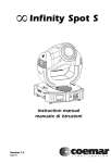
STANDARD AIRWORTHINESS CERTIFICATE
3
MANUFACIUF€FI AND MOOET
NAIIONALITY AND
N887SP
PIPER
.
AIFCRAFI SEFIAL
C¡''EGORY
NUMBEF
FEGISIFAIION MARXS
34-7350124
PL34-2OO
NORMAL
Erceplrcns
NONE.
TEFMS ANO CONOITIONS
13 olhe$¿* 6lrUEhGd Ùy lhc AdmrnÊlr!¡d ttlE
alfwo.lhln6scertÍEâlelse'leclmsslongasthemlnt€Énce.pfænlatiErulnlNm'mdelle¿lþßrGgclo'Íldm
åndlt!årrcr!nrsr€g6tda{¡mltll',qlæ
accordencewrthparrszr.¡¡lanãCi"rrheF-ederalAvelrmRegutelrons såppropfl¡l¿
Unlæs sæær surrenÓged. susp€nded rwoted or a lsmlnal¡on date
Slal6
OESIGNATION NUTTSEF
DATE OF ISSUANCE
SAT-FSDO S}I17
exc¡
rxe ¡ln'cn¡rr t¡¡ ¡t
Any attãatron, feptoouctton. or m¡suse ol lhlsGøllftcale may b€ puñEhâble by
yeåfs or both TH|S CERT|FICAfE MUsl BE otsel¡veo
AVIATION FEGULAfIONS
FAA Form g1(XÞ2 (B_s2)
¡r.¡
â
llne nol
(x lmÞrlsonmnt not€xcecdlfìg 3
WIÌH.APPLICABLE FEDERAL
GPO 570-189
\
-
WAYMAN AVIATION SERVI
Bldg.209 Musick Rd. Opa-Locka Aþort Opa-Locka, FL 33054 Ph: 305.685.6468
Piper Seneca
I
N887SP
E.L.T.
April2009
April2010
TRANSPONDER
April2008
April20l0
STATIC SYSTEM
April2008
April20l0
ANNUAL
April2009
April20l0
IOO HRS.
4,629.7 Tach
4,729.1Tach
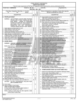
COMPUTED \ilEIGHT AND BALANCE
BASIC EMPTY WEIGHT
2862.8
TOTAL MOMENT
241794.1
NEW C.G.
84.46
USEFUL LOAD
t337.2
N8875P
WEIGHT AND BALANCE
DATE.
April 1, 2005'
wo#:
17A18
A/C
PIPER PA-34-2OO
S/N
34-7350124
:
REG#:
N887SP
:
TACH:
4138.9
THIS FORM SUPERSEDES WEIGHT AND BALANCE DATED:
ITEM
WEIGHT
ARM
(LBS.)
(tN)
MOMENT
(rN LBS.)
2871.80
84.30
242092.90
REM OVED LeÍt MZ-4216 Sta rter
-18.00
33.20
-597.60
NSTALLED Left MZ-6222 Starter
9.00
33.20
298.80
TOTAL:
2862.80
84.46
241794.10
PREVIOUS WEIGHT AND BAI-ANCE:
I
12117t01
NEW EMPry WEIGHT:
NEW EMPTY WEIGHT C.G.:
MAX GROSS WEIGHT:
USEFUL LOAD:
2862.80
84.46
4200.00
1337.20
LBS.
tN.
LBS.
LBS,
Take-Off
SYREK-MEE AVIATION
2?6-72
5L
NewPage I
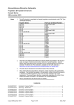
unitedstates ofAmerioa
S upp
Deparhent of Transportation
-
Federal Aviation Administration
lemental Type
Numb€T
C ertificate
"nor,**
Gamin Interndional, hc.
12fi) East 15lstsheet
Ol¿tle, Ks 6$62
This certificale issued to
certifies that the change in the t¡pe designfor thefollowing pductwith the limintions and conditions
thereþr as specified hereon meets lhe ainvorthiness requirements of Parl r of the Rdcr¡r Avi¿ion It egylations.
3Ar3
Original Product-Ty¡te Cenificate Number :
Makc : Piper
Model: PA-34
Description of Type Desrgn Change: krstallationofaGarrninGNs430/530 VIIFNAV/COMIWGPS
Systemand
064 Cquse Deviation Indicators (CDI), GT)K 327 ATCRBS Transpmder, and GMA 3 40 Audio ParæI. Data
Required: (l) GarminMasterDmwinglist (MDL) 005{000140,RevisicnE, d¿tedFebn¡ary 18,2003; and (2) FAAApprorrcd
Airplane Fligþt Manrnl Srpplemeú (AFMS),forPiperMo&swithGa¡minGNS 430 andGNS 530 VIIFNAV/COMIvIGPS and
associated GI I
GI 106ACor¡se Deviation l¡rlicators, Garminp66rmenf RevisioaB, dated Febn:a¡rJ 26,2003; orlaterFAAApprowdRevisions
to
(l)
or (2).
Limitations and Conditions
.' Cmpatibility of this desip change withpreviorsly approrædmodifioations must be
deterrnined by ^be installer. If tbe holder agrees to permit amtùør persm to uæ tlis certificate to alter tb prodrct ttre holder shall
give the otberperson written eviderpe ofthat permission
Date of application.'
May 3r, 2{Ð2
Date of íssuance.'Fórury
77,m03
This certíficaæ and the supporting data which is the basisfor approval shall remain in effect until
surrendered, suspended, revoked or a termination date is oútenvise esþblished by ùe Adminßtrator af the
F ed era I Aviation Ad m inistration.
Page
I
THE
I}IJPLIGATE
sjElrrE!tra
FILCIT'S¡ EIFEFIATING¡ MANIJAL
\r"
This nranual is incompleterithout an
FLIGHT MANUAL andan
WARNING
EXTREME CARE MUST BE EXERCISED TO LIMIT THE USE OF THIS MANUAL
TO APPLICABLE AIRCRAFT. THIS MANUAL REVISED AS iNDICATED BELOW
OR SUBSEQUENTLY REVISED IS VALID FOR USE WITH THE AIRPLANE
IDENTIFIED BELOW VfHEN APPROVED BY PIPER AIRCRAFT CORPORAflON.
SUBSEQUENT REVISIONS SUPPLIED BY PIPER AIRCRAFT CORPORATION
MUST BE PROPERLY INSERTED.
MODEL PA-34-2OO
I
AIRCRAFT SERIAL NO
34-7350L?4
REGISTRATION No. N Yî
PILOT'S OPERATTNG MANUAL, PART NU
.7
S. P
PR871 130
PIPER AIRCRAFT CORPOR.AJRON
APPROVAL SIGNATURE AND STAMP
bility of the owner.
for flight. The pilot
the Airplane Flight
Tltit Pilot's operating Manual is not desígned as aSuöltäuG fòr adequate and comperenr
-. - instruction, knowledge of the current
flight
ãirworthiness directiv"r,
federal air
regulations, or advisory circulars. It is not intended to be a guide for basic"p'pfiruble
hitrri-inrt.crion or a
training manual for transition from single to multi-engine fliing.
If an inconsistericy of information exists between the Pilot's Operating Manual
the
Airplane FIight Manual approved by the FAA, the Airplane FIight ú;*t.shall and
be the
authority.
A co_mplete or partiar replacement of this manual, part No.
761 506, may be obrained onry from piper custome¡ services.
Publ-shed bv
PU
BLICATIONS DEÉARTMENT
Piper Aircraft Corporation
76t 506
Issued: March 1972
GENERAL SPECI FICATIONS
APPLICABILITY
This manual is applicable to Piper Model PA-34-2OO aircraft having serial numbers
g4-725OOOl through lZ-lZSOt89 wheì Piper Kit ?60 607 is installed, 34-7250190 through
is installed a¡d 34-7250215 through 3Ç735O353. Contact
34-7ZSO2¡4 when Þiper Kit 760
on the application of this manual.
infonnation
specific
for
Piper Customer Serviðes
6ll
REVISIONS
The information compiled iri the Mot's Operating Manual will be kept current'by revisions
distributed to the airplane ou'ners.
Revision material will consist of information necessa¡y to update the text of the Present
manual and/or to add information to cover added airplane equipment.
L
Revisions
Revisions
will
be distributed whenever necessary as complete Page replacements or
in accordance with the instructions given below:
addirions and shall be inserted into the manual
l.
2,
i.
IL
Revision pages will reþlace only pages with the same Page number.
Insert aU ãAáit¡onal pages in proper numerical order within each section.
Page numbers followeO Uy asmall letter shall be inserted in direct sequence.with the
same common numbered Page.
ldentification of Rêvised Matérial
Revised text and illustrations shall be indicated by a btack vertical line along the left hand
margin of the page, opposite revised, added or deleted material. A line opposite the pa-ee
or illustration was
nurl", or section titié and printing date, will indicate that the textpage
u'as added.
entire
unchangèd bui material was relôcated to a different page or that an
Black lines will indicate only current revisions with changes and addi(ions to or deletions
of existing text and illustrations. Changes in capitalization, spelling, Punctuation or the physical
Iocation of material on a page will not be identified by symbols-
ru.
Original Pages Issued
The original pages issued for this manual prior to revision are given below:
rhrough 14, 2-l rhrough 2-22, 3-l through 3-26, 4-l through 4-14, 6- I through 6- l4'
7-1, 8-l through 8-16, 9-l through 9-l l.
|
-l
REVISIONS ISSUED
Current Permanent and Temporary Revisions to the PA-34 Pilot's Operating Manual issued
March lO,1972 are as follows:
Permanent Revision to F/M
Dated May 8,1912
76t so6 (PR720707)
Permanent Revision
Dated
761 506(PR720802)
Permanent Revision to W/B
761 506 (PR720802)
Permanent Revision to FIM
General Specifications
Dated August 2,1972
76t
506 (PR7209rs)
Permanent Revision to F/M
Dated September 15, 1972
761 so6 (PR72r I t6)
Permanent Revision to F/M
Dated November 16,1972
76t
506 (PR720s08)
'
luly7,1972
Dated August 2,1972
& \ry/B
761 506 (PR72t22O)
Permanent Revision to F/M
Dated December 20,1972
&.Pto/M
WB
761 506 (PR72t22t)
Permanent Revision to
761 so6 (PR73052s)
Permanent Revision to F/M
Dated May 25,1973
761 s06.(PR73O9t9)
Permanent Revision to F/M,
Dated September 19, 1973
&wB
WB
Dated December 21,1972
and P/O/M
76t so6 (PR73r026)
Permanent Revision to P/O/M
Dated October 26,1973
761 s06(PR74O426)
Permanent Revision to F/M,
Dated Apnl26,1974
WIB and PIOIM
761 506 (PR74r0r4)
Permanent Revision to F/M,
WB
76t s06 (PR7sOs30)
and
Dated October 14,1974
PIOIM
Permanent Revision to F/M,
Dated May 30, 1975
W/B and PIOIM
761 506 (PR7508r9)
Permanent Revision to F/M
Dated August 19,1975
and P/O/M
761 506 (PR77OlmI)
Permanent Revision to F/M
Dated
April I ,1977
and P/O/M
76t
506 (PR790323)
Permanent Revision to W/B
Dated March 23,1979
and P/O/M
76r s06 (PR830614)
Permanent Revision to F/M
and P/O/M
DatedJune 14, 1983
REVISIONS ISSUED(conÐ
Current Permanent and Temporary Revisions to lhe PÀ-34 Pilot's Operating Manual issued
March lO,1972 are as follows (continuÞd):
761 506 (PRS7I
t30)
Permaúent Revision
WB
and P/OIM
to
Dated November 30, 1987
BLANK PAGE
TABLE OF CONTENTS
GENERAL SPECIFI GATIO NS
DESCHPT|ON - AIRPIÁNEAND SYSTEMS
FLIGHT MANUAL FAA APPROVED
EMERGENCY PROCEDURE FAA APPROVED
WEIGHT AIIID BALANGE
O
PERATING INSTRUCIIONS
OPERAIING TIPS
PERFORMANCE CHARTS
HANDLING AND SERVICING
BLANK PAGE
GEN
Altitude Cruising Speeds (mph)
Weights
ERAL SPEGI
FI GATI ON S
BLANK PAGE
SENECA
GENERAL SPECIFICATIONS
PERFORMANCE
rplanes flown at gross
y"igll
under standard
ornancet;;';tdiftcairplãnemavvaryfrom
airplane
instailea]ih""ã;;;itton if engines'
rg technique'
)
)oo)
,,åi,"r!Lo"ed
(mPh)
off¡
ower
(gear and flaps down) (power
|
4200
800
4000
750
(l60)
6? (ss)
zg (63'5)
185
183.4 (159.s)
ó9 (60)
76 (66)
705+**
MiîliiiÏîI:'it{.üiËil
*200 BHp, counter-Rotating Engines,
1,oBB ì1.3 S,
\ùteigltt'
Pounds Gross
crilinrä.i.u;';l'iôiõ
**5000 Ft. single Engine service
vs DensitY
*+*ThiSvalueappliesonlyfortheconditionsstatedontheLandingDistance
Altitude Chart'
GENERAL SPECIFICATIONS
nEVlSnOt MaY 30' 1975
1-l
SENECA
WEIGHTS
Gross Weight (lbs) Max. Take-off
4200
Max. Landing
Empty Weight (Standard) (lbs)
USEFUL LOAD (Standard) (tbs)
+These weights are approximate
¡1000
2625+
I 575+
POWER PLANT
Right Engine - Lycoming
Left Engine - Lycoming
Rated Horsepower
Rated Speed (rpm)
Bore (in.)
Stroke (in-)
Displacement (cubic in.)
Compression Ratio
Dry V/eight (lbs)
LIO-360-ClE6
IO-360-ClE6
200
2700
5.125
4.375
361.0
8.7: I
350.0
FUEL AND OIL
Fuel Capaciry (U.S. gal)
Unusable fuel
Fuel, Aviation Grade (minimum octane)
Oil Capaciry (qrs) (each engine)
98
5
I
00/l 30
8
BAGGAGE AREA
100
100
15.3
20
24
x2l
DIMENSIONS
Wing Span (ft)
Wing Area (sq ft)
Length (ft)
Height (ft)
Wing Loading (lbs per sq ft)
Power Loading (lbs per hp)
Propeller Diameter (in.)
t-2
38.88
208.7
28.5
9.9
20.1
10.5
?6
GENERAL SPECIFICATIONS
REVISED: May 30, 1975
LANDING CEAR
Wheel Base (ft)
rrffheel Tread (ft)
llre
P¡essure
Tire
Size
(psi)
Nose
Main
Nose (six-ply rating)
Main (eight-ply rating)
CENERAL SPECIFICATIONS
ISSIJED: Marrch t0,1972
t-3
SENECA
ll' .tt"
cln¡t ur¡ uil
srtt $t. r!¡.¡2t
l4
GENERAL SPECIFICATIONS
ISSUEÐ: March t0,1972
DESCRIPÏION
AIRPLANE AND SYSTEMS
DESCRIPTION
AIRPLANE AND SYSTEM
2-1
The Airplane .................
2-l
Airframe....
2-2
Engines
Propellers
Landing Gear System
Flight Control
Fuel System
Systems..............:....
Electrilal System
Vacuum System
Instrument Panel .........
Pitot-Static Systems.....
Heating, Ventilating and Defrosting System
Ice hotection System
Seats..........
Finish
Baggage Area -...-.....
Stall Waming .......---.-....
..--...-..1.---...-
2-4
2-4
2-9
2-to
......--.----..-....
2-12
2-16
2-r 8
2-r8
2-20
2-22
2-26
2-26
2-26
aa1
BLANK PAGE
SENECA
DESCRIPTION
AIRPLANE AND SYSTEMS
THE AIRPLÄNE
The Seneca is a twin-engine, all metal retractable landing gear airplane. It has seating for up to
seven occupants and two separate luggage compartments.
AIRFRAME
Except for the steel used in the engine mount and landing gear, añd the-fiberglass used in
such portibns as the nose and wing tips, the structural components of the airframe are made of
aircraft aluminum alloy which has been heat treated and protected from corrosion. The airframe
has been designed and- tested to a limit positive load factor of 3.8. The Seneca is not designed
for acrobatic flight, and consequently aerobatics ar'è prohibited.--(il
The fuselage is a conventional-semi-monocoqu-e_structure, which h9s a- front door on the
right sidè,and irear door on the left. An additional large-size rear door, which facilitates the
toãOing of large pieces of cargo, is available
The wing is of conventional metal design using one main spar located at approximately
g
4O7o of the.chord afi of the leading edge, t
e
taking
to
assist
in
and
the flaps and ailerons
e
a
four-position
by
mechanically operated
o
provided to reduce landing speed and to give th
interconnected fuel tanks form an integral part of each wing. Both tanks on one side are filled
through a single filler neck located well outboard of the engine nacelle.
AIRPLANE AND SYSTEMS
REVISED: JUNE 14,1983
2-l
SENECA
The wings are atlached to each side of the fuselage by the butt ends of the main spars,
which are bolted into a spar box carry through, an integral part of the fuselage structure. fhere
are also fore and aft attachments at the rear spar and at an aux¡liary front spar.
The empennage of the Seneca consists of a vertical stabilizer, a rudder, and a horizontal
stabilator. The rudder has a trim tab capable of relieving the pilot of excessive pedal force
during single-engine operation. The stabilator incorporates an anti-servo tab which improves
longitudinal stability and provides longitudinal trim. This tab moves in the directiõn the
stabilator moves but with increased travel.
ENGINES
The 400 total horsepo\Mer of the Sqneca engines makes possible a high cruise speed and
excelle¡t ciimb performance. The aircraft is powered by'two four-cy-linder, Lt'coming,
fuel-injected engines, each rated at 200 horsepowei at 2700 RPM. Aiymmetric rhrust ls
eliminated during lake-off and climb by counter-rotation of the engines, the lefi engine rotating
in a clockwise direction when viewed from the cockpit and the right engine rorarin!
counterclOckwise.
The engine compartments are easily accessible for inspection through top-hinged side
panels on either side of the engine cowlings. The cowlings are cantilever stnictures, attached at
the firewalls. Engine mounts are cons¡ructed of steel tubing, and dynafocat mounts are provided
to reduce vibration.
The exhaust system is a crossover type, with exhauSt gases directed outboard of the
aii for the cabin and
nacelles into muffler-heaters to minimize exhaust noise and provide heated
def¡oster.
The cowl flaps are löcated on the bottom of the engine nacelle and are manually operated
by control levers below the throttle quadrant. The control levers have three positiónsi open,
intermediate and closed. A lock, incorporated into each control lever, locks the cowl flap in tne
selected position- To operate, depress the lock and move the control to the desired pôsition.
Release the lock after initial moveinent of the control; the flap will then stop auromaiically in
the next intermediate, open or ilosed position. The lock must be depressed foi each selectioí of
cowl flap.
An oil cooler for each engine is mounted on the forward side of the firewall. Air is picked
air scoops on the side of the cowl, passed through tþe oil cooler and ducted overbóard in
the lower cowling.
uP by
The fuel injection system reduces the possibility of induction system ice and provides
better fuel distribution than does a carburetor system. Each engine is equipped with ã Bendix
RSA-5 fuel injection system, which operates on the principle of meãiuring engine air
consurnption and using the air flow to control fuel flow to the engine. Fuel pressuie regulation
by means of a servo valve causes a minimal drop in fuel pressure throuChout the met"ring
system. Metering pressure is maintained above vapor forming conditions, yei fuel inlet pressurã
is low enough to allow lhe use of a diaphragm fuel pump. Thus vapor lock and asiociated
problems of difficult starting are minimized.
2-2
AIRPLANE AND SYSTEMS
REVISED: MARCH 23,1979
SBNECA
PROPBLLERS
counter-rotation,of the propellqrs provides balanced thrust during
hke-off and climb and
eliminales rhe "criticar enginel' fãctorin iingre-engi"" ¡¡gtil
rgal
¡ny
I to
:dd
hering during engine
is less rhan gó0 nÞU.
t be sure to move the
I,ANDING GEAR SYSTEM
To increase cruise speed, climb
retractable tricycle landing gear, which
a heavy duty braking system permit ope
24
he Seneca is equipped with a
n"ggàã-Ë; consrruction and
of landing areas.
AIRPLANE AND SYSTEMS
ISSUED: March tO,tgTZ
SENECA
possible.
take-off.
to pfevent
a smooth' not-too-rapid movement
All throttle opefations should be made withcounterwei$hts
on the engines'
to åynamic
unnecessary engine wear, or damage
Thepilotslquldreadandfollow.theproceduresrecommendedintheLycomingoper4tor's
between
outain'maximum engine efficiency and time
Manuaì for this engine, in order to
overhauls.
englne
/
PULL-CTJOSE
L Êlht
R
Pr.lsH-oPEt{
Cowl Flap Control
AIRPLANE AND SYSTEMS
ISSUED: March 10,1972
,-\
SENECA
released bY liYdraulic Pressure'
the gear,
ren desired
if there has not been any apparent
nd the selector is in the correspondin! position'
mP' Three green
t
the left engine
n
I
in the full uP
not
f
u
If
illuminate when the gear down position has been
one or two of the three green lights do not
the following conditions
the lights that is out,
selected, this courd indicate thãr for e"crt-or
might exist:
a. The gear is not locked down'
anyìf
b.
c.
The bulb is burned out'
There is a malfunction in the indicating system'
ãnd moved around in order to check the bulbs'
The square indicating lights can be pulled out
Amicroswitchincorporatedinthethrottlequadrantactivatesawarninghornunderthe
both
åi*tiiind manifold pressure reduced berow r 4 inches on either one or
following
z.
engines.
airplane is on the ground'
Gear selector switch in the UP position when the
AIRPLANE AND SYSTEMS
REVISED: MARCH 23,1979
2-5
SENECA
If the gear selector knob is placed in the 'l
a safety switch located on the left main ge¡rr u
the master switch should be turned on. On tal
inches, the safety switch closes to complete thr
landing gear when the gear switch is moved to I
letracted before an airspeed of 125 MPH is e:
I50 MPH.
The nose gear is.steerable through a 42-degree arc by use of the rudder pedals. As
the gear
retracts, the steering linkage disengages to reduce rudder pedal loads in flight
änd the nose wheel
straightens as it enters the wheel well. A €€ar centering spring, incorpoiareJ in thg nose gear
steering system, prevenls any tendency to shimmy.
The hydraulic reservoir for landing gear operation is an integral part of the gear hydraulic
pumP- Acpess to th-e.combination pump and reservoir is th_rough-a panel in ìÀ"
nor" úaggag"
compartment. For filling instructions see the seneca service Manual.
The three landing gear wheels are the same size - 6.00-6. The nose wheel has a 6-pty tire
and the main gear has 8-ply ti¡es. Struts for nose and main gear are air-oil assemblies.
The brake system, which incorporates a sì
main gear sfrut, is designed to meet all normal
short-field landing capabilities of the Seneca. y'
of the landing gear hydraulic reservoir, i$ loc¿
baggage compartment. The fluid Should be mair
brake assemblies are actuated by individual toe brake cylinders mounted on the left (optional
9n lhe right) set of rudder pedals and,a handle-operated brake cylinder located below and
behind the lÞft center of the instrumenr panel.
parking brake is actuated by pulling back on the handle and pushins forward on rhe
-buttonThe
to rhe left of rhe handle. Ths
brake can be released by pulling
touching the button, and allowing the handle to swing forward.
ù@e,
l!¡¡
cE¡t
"n
on tnã nan¿ie *iifrã"i
ErËrcr.
¡o r¿¡¡x¡E. sEE l.f.Í.
ITO|¡ E.EiGAGE.ET¡.
Landing Gear_Actuator
24
AIRPLANE AND SYSTEMS
REVISED: Aprit t,1977
SENECA
LEFT MAIN GEAR
I{YDRAULIC CYLINDER
RIGHÎ MAIN GEAR
HYDRAUUC CYLINDER
RESTRICR}R
I
r--
PRESSURE
SffTCH
-${-
CHECI( VALVE
FREE FALL
CONIROL
Hydraulic System Scherhatic
AIRPLANE AND SYSTEMS
ISSLIED: March lO,1972
2-7
SENECA
LA¡OII{G oEAR
-
ELECIRO
HYI'RÂUL¡C
Plr[P 25 ÂHP
LIXOIIIG
G€AR
cotrïRoL a
wlRilITG 3 AIIP
TERIIINAI.
.
È
I
'
4
I TO
r{Av
LrGHlS
Landing Gear Electrical Schematic
2-8
AIRPLANE AND SYSTEMS
ISSUED: March 10,t972
SENECA
FLIGHT CONTROL SYSTEMS
Dual controls are provided as standard equipment, with a cable system used between the
controls and the surfaceì. The horizontal tail (stabilator) is of the all movable slab type, with an
anti-servo tab which also acts as a longitudinal trim tab, actuated by a control mounted on the
conirol tunnel between the two front séats- The stabilator provides stability and controllability
with less size, drag and weight than the more conventional horizontal stabilizer-elevator
combination. The ailerons are provided with a differential action and are tightly interconnected
by springs with the rudder. ihis arrangement tends to eliminate adverse yaw in turning
maneuveis and to reduce the amount of coordination required in normal turns.
The flaps are manually extended, aerodynamically balanced for light operating forces and
spring loadeä to return to ihe retracted position. The flap control lever is located between the
fiont-seats on ihe floor. A button on the end of the lever must be depressed before moving the
controt. A past center lock incorporated in the actuating linkage hotds th-e flap when it is in'the
retracted päsition so that it may be used as a step on the dght side. Since the flap will not
supporr a ìtep load except whrln in the fúll retracted positiori, it should be completely retractd
*ñen people are entering and leaving the aircraft. The flaps have three extended posilions, l0'
25 and 40 degrees.
Console
AIRPLANE AND SYSTEMS
ISSUED: March lû,l972
2-9
SENECA
FUBL SYSTEM
The Seneca fuel system offers Jwo 24-5 gallon aluminum lanks in each wing which are
interconnected to eliminate probelms of tank selection and fuel management. Both tanks in each
wing are filled with a single opening in the outboard tank, and fuel from the outboard tank flows
into the inboard tank as the fuel from the inboard tank is consumed. The 98 gallon fuel capacity has
only 2-ll2 unusable gallons on each side, making a total of 93 usable gallons. The fuel must to
lO0/l3O octane (light green).
An engine-driven fuel pump is the primary means of supplying fuel for each engine. An electric
fuel pump, located on the aft side of the firewall, is provided for each engine as a back-up in case of
engine-driven fuel pump failure. The electric pump should bc used during landings and take-offs to
ensure sufficient fuel pressure in case of an engine{riven fuel pump failure during these portions of
the flight sequence. Switches for the electric fuel pumps are conveniently located on the switch
panel to the left of the pilot.
In normal operation, each engine operates with an independent fuel system, drawing fuel from
the tanks in the wing on the same.side as the engine. However, the two $ystems a¡e interconnected
by crossfeed lines which will permit an engine to use fi¡el from the tanks on the opposite side in order
to extend single-engine range and to enable the pilot to keep fuel weight balanced. \lfhen crossfeed
has been used during single-engine cruise operation, prior to landing the fuel selector should be
positioned so that fuel is used from the same side as the operating engine. The fuel selectors, located
on the funnel between the pilot and the copilot seats, reflect the simplified fuel system- Each lever
has three positions: OFF, ON and CROSSF,EED.
NOTE
Do not operate wirh both fuel selectors on CROSSFEED. Do not
take off with a selector on CROSSFEED.
To permit the pilot to monitor the system, fuel pressure, fuel flow and fuel quantity gauges (a
single fuel gauge for the two tanks in each wing) are mounted on the instrument panel, Fuel
quantity sender units, one mounted in each fuel tank, transmit electrically the total quantity of fuel
in each pair oftanks.
A gascolator (fuel filter) is locaæd between the fuel selector valve and the electric fuel pump on
each side. Quick drains are provided for. the fuel gascolators (2), fo¡ each fuel tank (4) ánd åach
crossfeed line (2). Two fuel tank drains are located under each wing; crossfeed drains are located
under the belly of the aircraft opposite the trailing edge of the right wing flap; gascolaror drains are
on the inboard side of the engine nacelles, forward and below the leading edge of the wing. The vent
system for the fuel tanks consists of a vent in each fuel cap, a vent interconnect between the tanks in
each wing, and an overflow line from the top of each filler neck.
2-t0
AIRPLANE AND SYSTEMS
REVISED: MARCH 23,1979
.
SENECA
,t
2
GÙ¡=
o
ts
È,
C¡
u=
E
l¡,
-c¡
ô
ä¡
ti5P¡¡,
o
=
E
Fuel Schematic
AIRPLANE AND SYSTEMS
ISSUED: March 10,1972
2-ll
SENECA
ELECTRICAL SYSTEM
The electrical system of the Seneca is capable of supplying current for complete night IFR
equipment. Electrical power is supplied by two 60-ampere alternators, one mounted on each
engine. A 35 ampere-hour 12 volt battery provides cunent for starting, for use when the engines are
not running, and for a source of stored electrical power to back up the alternator output. The
battery, which is located in the nose section and is accessible through the forward baggage
compartment, is normally kept charged by the alternators. If it becomes necessary to charge the
battery, it should be removed from the airplane.
An external power source plug is available as optional equipment, and when installed is
located on the lower left side of the nose. While an external 12-14 voltpower source is being plugged
in or unplugged, the master switch should be in the OFF position to prevent sparking. ftre máJter
switch should be in the ON position, however, for engine starting with exæmal power.
Two solid state voltage regulators'are provided to maintain effective load sharing while
regulating the electrical system bus voltage to 14.0 volts.In each alternator cifcuit an overvoltage
relay is provided to prevent electricãl damage to electrical and avionic equipment, by taking the
alternator off the line if its output go.es above 14.0 volts. When this occurs, a red light located on the
left side switch panel illuminates to indicate that the overvoltage relay has tripped. This is the only
finction of this light; it does not necessarily come on for other failures of the alternator system.
Voltage regulators and overvoltage relays are mounted on the forward side of the bulkhead at
station 49.5
Circuit breakers are provided to protect equipment and the electical s)¡stem- These are located
on the lower right hand instrument partel, and theie is room for additional ci¡cuit breakers if extra
elect¡ical equipmenr is installed. A circuit breaker may trip automaticàlly in case of equipment
malfunctions or a sudden surge of curren!. The pilot can then reset it by pushing it in (preferably
afaer a few minutes cooling period). However, he cannot pull out a circuit breaker manually.
Most of the electrical switches, includ-ing the master switch and those fo¡ the magnetos, fuel
pumps, starter, alternators, lights and pítot heat, are conveniently located on the switch panel to the
left of the pilot. A press switch near the top of the alternator-master switch panel turns on a light
which is wired around the master switch and which permits the pilot to inspect the panel at night
before turning on the master switch.
The alternator system has rhe aàvantage of being able to produce rated electrical output at low
engine speed. The pilot of the Seneca is provided with an e¡rsy means of monitoring electrical system
operation with dual ammeters and overvoltage warning lights. An ammeter is provided for each
alternator. This acts as'a load-meter, showing the amount of current being produced by the
particular altemator. A zero readíng would indicate that the altemator was not producing current.
An indication near 60 would show that the elect¡ical demand was taxing the alternator. In this case
the pilot should turn off unnecossaÐr electrical equipment to reduce the current required. When
operating on a single engine, the pilot should be on guard against demanding too much from the
one operating alternator because an overloaded alternator may burn out or its circuit breaker may
trip,
2-12
AIRPLANE AND SYSTEMS
REVISED: MARCH 23,1979
SENECA
@
ru
AIRPLANE AND SYSTEMS
ISSUED: March tO'1972
#S*^
-î
ffiiî
2-13
SENECA
texremil
- -ì
suPPLy , I
I POWER
I
RIEHT
ALlERI{ÂIOR
SWITCH PANEL
LIGHÎ
:STARTER
SOLENOID
RELÂYS
:
Alternator and starrer schematic (ser. Nos.
2-14
i+72sw0l
thru 34-7350135)
AIRPLANE AND SYSTEMS
REVISED: Aprit26,lg74
SENECA
l-q¡!¡tar--ì
,_ ,-i l- ,ï\ì
-
æi,ãi
l-61Ð-rçi I I
1r=
lllÉ-'l
ilLËËl-=
I
t_
__-
-J
I
I
É
r-r
ALIER¡¡AIOR
FIELO
FTELC
/lul.¡r,
r
^,,ÉËñÀ,Æ
I
;l
ll*,."n^,o,
Ài*îr"L-+sn{*.**
----;flfiiJ,i"'
i al.l ¿xlrl
LIGHT
LEFT
OVER.
wnã,o liË^ri&.|
YOLIAGE
L¡GHI
I
^
OVER.
VOLTAGE
lr-11""
NELÂY
IJ:
-
t-'
I
lot
I
swrTcH
,
I
al
I
I
I
.t
ALIERT{ATOR
AELAY
I. RIGHT ALTERNAIOR
= FIELD RELAY
=
LEFT
fsr n6. t¡l-?:llozAs
SfÄRÎEñ
f1:7¡3o3€t r+
3¡ ßq¡rrdl
,
LEFT
S1ìÀRIER
SOLENOID
RELAYS
RIGHI
VOLTAGE
REGULAIOR
-¿)t
'lr
II
II .l'
rlb---
VOLTAGE
REGULATOR
ttl
II
RTGHT l c
STARIER\ RIGI'IT
Ai¡lIETER
A ÌLCFI
AMI'ETER
I
\,/
ALTÊ.RI{ATORS
Altemator and Starter Schematic (Ser. Nos. 34-7350136 thru 3+7350363)
AIRPLANE AND SYSTEMS
REVISED: April26,l974
2-rs
SENECA
\ù/hen all electrical equipment is turned off (except the master switch), the ammeters will
indicate cuffent being used to charge the battery and operate instrumentation. If the sum of the
two readings is significant, this is an indication that the battery has a low charge. The pilot
should try to determine why it is low, and if no cause is apparent the condition of the battery
and the elèctrical system should be checked by a mechanic.
If during flight both alternators should fail, the battery becomes the only source of
electrical pou,er. Therefore all unnecessary equipment should be turned off. How long the
battery will be able to supply the necessary equipment depends on the current drain of the
equipment, time it took the pilot to notice the dual failure and the condition of the battery.
During night or ¡nstrument fliglit the pilot should continuously monitor the ammeters and
warning lights so that he can take prompt borrective action if electrical malfunction occurs.
Procedu¡es.for dealing wilh electrical malfunction are covered in the Airplane Flight Manual.
VACUUM SYSTEM{.
The directional gyros and attitude indicators are operated by air drawn from the cabin
through a filter and the instruments to the engine nacelle by a vacuum system. The vacuum
system consists of one vacuum pump installed on each engine, plus plumbing and regulating
hardware. If a second set of gyro instruments is installed, a second filter will be added for these
instruments. The instruments are protected by a yacuum regulator mounted on the right aft side
of each firewall. The regulators maintain a vacuum of 5.0 t .l inches of mercury ar 2000 RPM.
Suction is indicated by a vacuum gauge mounted to ihe left of the right control column.-A
vacuum less than 4.5 indicates a'low'air flow through the gyro iristruments, with possibly
inaccurate readings. Also incorporated in the system is a check valve, which is located behind
the instrument panel on the upper right side of the baggage compartment bulkhead
If suction is lost from either vacuum pump or from a leak in the hose of either side, the
valve automatically closes and vacuum is supplied by orte pump. In this case, one of two red
malfunction buttons appears on the face of the vacuum gauge, indicating that vacuum is not
available from that side. Each pump alone has sufficient capacity to operate a dual set of gyro
instruments up to a 12,500-foot altitude. When operating with a single vacuum pump above that
altitude, a high RPM setting must be maintained to get adequate suction for dual flight
instruments.
Air filters are incorporated in the vacuum system to increase the life of the gyros. They are
mounted behind the instrument panel in the upper corners of the baggage compartment and
should be cleaned regularly+Optional Equipment
2-16
AIRPLANE AND SYSTEMS
REVISED: lryril26,l974
2â
Eã
i'3
Ëi
sE
VACUUH MANIFOID
(n
c,
É
3
(n
()
o
3
ô
BEGULATOR
REGULATOR
VÀCUUM GÀGE
LEFT ENGIHE
VACUUM PUMP
BIGHT ET¡GIiIÊ
VACUUM PUMP
u2
tll
h)
I
\¡
ztã
o
Þ
SENECA
INSTRUMENT PANEL
The wide instrument panel of the Seneca offers sufficient sPace for two complete sets of
flight instruments Plus engine
Dual flight instruments are oP
avionics permits an equiPment
and avionics are grouPed in t
inslrumenls and circuit breakers are located on
instruments are conveniently separated by the control wheel shaft on the left side. In spite of the
large instrument panel, over-tñe-nose visibility is good. A combination of white post lights
(opìional) and red floodlights eilsure easy reading of the instruments at night.
PITOT-STATIC SYSTEMS
pitot (total) pressure for the airspeed indicator is sensed by the aluminum mast mounted
under the left wing. Static pressure for the altimeter, vettical speed and airspeed indicators is
sensed by two static pressure units, one located on each side of the rear part of the fuselage'
Differenóes in static pt"ssute caused by a slip ot skid are balanced out by a connection of the
two static sources inside the fuselage.
The pitor mast can be equipped with a heating element to eliminate problems from ice or
heavy raín. The static pressure sensors. are not heated becati.se experienqe indicates they are not
likely to ice up. An alternate static'soi¡rce control vhlve is located below the instrument Panel,
to the right of the power quadrant- When the valve is set to alternate position, the altimeter,
pressufe.
vertical speed indicãtor and.airspeed indiiator will be using
within
on
readings,
give
different
slightly
These instruments may then
the
storm
ventilating
heating
and
the cabin. Airspeed, setting Öf the
pressure
affects
the
static
alternate
pilot
how
his
pressure.
A
can
see
window can influence cabin
and
ventilation
airspeeds
different
to
the
at
other
instruments, by switching from one source
configurations (including open storm window below 150 MPH).
The holes in the sensors for pitot and static pressure must be fully open and free from dirt,
bugs and polish. If one or rnore of the pitot-static instruments malfunctions these pressure
*yst"-r should be checked for leaks, dirt or water. If moistu¡e is present, the static system can
bê drained by turning on the alternate static system. Thq selector valve is located at the low
point of the sysrem. Another drain is provided in the lower left f¡ont side panel to drain
moisture from the þressurè line running between the pitot mast and the instrument panel.
2-18
AIRPLANE AND SYSTEMS
ISSLIED: March 10,1972
F>
n=
É;
nrt
Øttrt>
vz
:Þ
ÈÞ
,zz
.? ut
r-{
\o ct
\¡ F¡
ut frí
3
(t)
@l
v2
T
É
5
o
Þ
It{rs
o
I8.
t. ADF II.IDICATOF
STALL WARNING LIGI{T
TURN AND 8ÂNK INDICATOR
AIRSPEED INDICÂTOR
DINEClIOI.IAL GYRO
,lTTlTU0E GYFO
n VERTICAL SPEED II,¡DICAIOR
o GEAR UP LIGI{T
t0. ALTIMETEF
t t. OMNI INDICATORS
Gt.lDE-SLOPE INOIC^TOnS
r2. oMlll
^NDBEÂCOI¡ RECEIVER LIGH I S
I3. MARKER
I4. , MAGNETIC COMPASS
I5, AUDIO CONTFOL PAI,IEL
16. COMTvtUNICÂTIONS AND N/\VIGÂllOr'l
TRANSCEIvEHS (NO.-1.)
3.
4.
5.
6,
l*)
t
7.
COlvlMU?',llC^TIONS Ar'lD
TRANSCEIVERS INO..2,)
TRAl,ISPONDEN
l¡ll
36.
l9.r ADF RECË|VEn
2. CLOCK
I
¡
NAVIG^rlCrl
20. DME CONTROL AND INDICATOB
2l
.
lUNf.¡
A?.ID
BAfJK INDICAÎOR (COPILOTSI
INOICATOn'(coÞlLorsl
orRçÇlíoNAL GYFO (COPILOTSI
24. ÂLllf uoE GYFO ICOPILOTSI
25. VEBIICAI SPEED INDICATOR (COÞILOTS)
22. AtnSPEED
'23.
26. ALItMETER (COPILOlS)
27. CIGAR LIGI{TEH
?8.
?9.
cLocK (coPrLolS)
ulKE
PIIONE J,rCkS
30.
^l.tD llln-l
FUEL
^ulonlLol
31. ^LTIM^lrc
LËFT ENGIIIE AI,ID
IIISTRUTJiEI'¡T CLUS"f ER
32. OMlll-COUPLER
33. PrïCH lnrM
34, MAI'IIFOLO PRESSIJNF'G¡\UGE
35. LEFÎ EltctfrE T^Cr"rotlETEn
37.
38.
39.
40.
NIGIT ENGINE AND FUEL
INSIRUMENT CLUSTER
FIGHl ENGINE TÂCI{OMElER
LANDING GEAß DOWN LIGHÍS
L,\NDING GE¡\ß SELECTON
L,\NDING GEÂN FREE F^LL
v^LvE COI{InoL
41. AL ¡ EN}IAT E /\IR CONTROL
tl2. cor.tf Ro[ ou^oFANT
43. TEFI AMP MËTER
â4. P,\¡IEL LIG}IT SWITCH
.t
5.
RIGIIÍ /\MP ME'ÌFN
PNESSUNE G^UGE
46, FUCL TLOW
47. EGT GAUGE ^ND
48. GYNO SUCTION GAUGE
49. CIFCUIÎ BREAKER PANEL'
50, IIEAT AND DEFNOST CONTNOLS
51. I,JIIKE A¡ID PIIONE JACKS (COPILOf SI
v)
F'
zlã
o
Þ
SI'NECA
HUATING. \¡ENTILATING AND DEFROSTING SYSTEI\4
The heating and ventilating systent is designed to provide maximum comfort and
conrrollabiliry for pilot and passengers. wirh variable temperature-fresh air controls on the
inslrunrenl prnel and individual fresh air outlets controlled b1' the occupants.
Cabin and defrost heat is provided b)] a heat exchanger mounted on the exhaust manifold
of each engine. Air is taken in through a scoop on the outboa¡d side of each cowling and is then
ducred rhrough lhe heater muff. where it is heated by the exhaust manifold. A heat and defrost
valve located on the forward side of the firewall sends some of the airdirectly to the u'indshield
outlets l,hcn defrost is selec[ed and sends the rest of rhe air ro the lemperature-fresh air control
bor.. s,hich regulates the temperature of the air to be introduced into the cabin interio¡. Fresh
air for the cabin inlerior is taken in through inlets located in the.leading edge of each u,ing. The
frêsh air is forced into the temperature-fresh air control box rvhe¡e it is mixed u,ith heated air
fronr thc hsat exchanger (as selected) and then into the cabin interior.
The cabin heat and defroster controls are located on the right side of the instrument panel.
The defroster is equipped u'ilh a blorver for use during ground operation to defog the
n'indshield. The blorver is energized ç'hen the mechanical defroster control lever is placed in the
"full on" or "hi" position. The blorver can, be turned off in fli-eht b,r' moving the ôonrrol lever
a\À'a¡r f¡¡* the "full on" or "hil'position approximately one inch. When cabin heat and defrost
heat controls are in the "OFF" position. heated air from the heat exchanger is dumped
overboard- If maximum defrosting is desired, the heat to the cabin interior should be rurned off
and the defroster turned full on. An outlet near the feet of each occupant permits a flow of
eithcr heated or ventilating air, as selected by the control on the instrument panel.
Individual overhead fresh air outleß supply fresh air from an inlet located on each side of
the lower leading edge of the. vertical f-rn. The air is ducted to a plenum chamber and then ro
each individual adju.stable outlet located in the ceiling, The amouni and direcrion of air can be
regulated f<¡r inclividuat comfort. Rotating the fim of the outlet regulates the amount of air
(clockwise to decrease the amounL counlerclockwise to increase it), and moving the outlet in
the desired direction of the air flou, regulatés the direction..
COMBUSTIOnN HEATER*
An oplional Janitrol combustion heater installed in the afi fuseláge provides added air for
cabin hcating and windshield defrosting. The combusrion heateî can be used to supplemenr the
.standard muff-heater system.
Operation of the combustion heater is controlled by a three position switch locared on a
heater control console between the pilot's and copilot's seats, and labeled FAN. OFF, and
HEATER. The "FAN" position will óperate the ventilation blower only and may be used for
cabin ventilation or windshield defogging on the ground when heat is not desi¡ed.
The defroster conlrol lever for the standard muff-heater s!'stem must be in the ..HI"
position in order to energize the defroster blorver any time defrostiirg or defoggin-s is desired,
with or without heat.
*Optional Equipment
2-20
AIRPLANE AND SYSTEMS
REYISED: December 20. 1972
SENECA
For cabin heat, the air intake lever located on the heater control console must be Partial¡y
or fully open and ihe three position switch set to "HEATER." This will start fuel flow and
ignite íh"'Uu-.t simultaneouity. Witt instant starting and¡o need for priming, heat should be
felt within a few seconds. Two safety switches whicñ are installed and activated by the intake
valve located aft of the Janitrol heatLr unit are wired to prevent both fan and heater operation
unless the air intake lever is moved off the closed position.
Regulating the combusti
¡he heater control console bet
the air intake valve. The left
circulation can be maintained
desires.
Heat may be supplied to wann the cabin before staÌt¡ng engines ùy turning on the master
switch, insuring mixiure in the idle cut-off position, turning on the tt-q!t.gliltary fuel pumP,
opening rhe airlntake lever and placing the three position swilch in the HEATER position-
The combustion cabin heater uses gasoline from the fuel line between the engine driven
pump and injector on the right engine. Heater fuel consumptiolt- is one half gallon per hour.
Fuel used for heater operatiõn st¡oulO be considered for Flight Planning Purposes- If the right
fuel selector is in the off position the heater is inoperative.
of right engine failure the heater can be operated by leaving. the Juel selector on,
that rhe i,¡*turã control is in idle cut=off position, while oPerâting the auxiliary fuel
insuring
-Before
the hearer is operated under these conditions, determine that there are no fuel
pump.
In
case
leaks between the tank and the engine.
Located in the heater is a heat limit overheat switch, which acts as a safèty device to render
the hearer system inoperative if a malfunction should occur. Operation q mjS switch results in
illumination of the ovirheat light located on the healer control console. The heat limit switch is
locafed in fhe forward outboa;d end of the heater vent jacket, with a red reset bÚtton on the
hearer shroud and can be reached through the bulkhead access panel into the aft fuselage.
To prevent activation of the overheat limi
ground operation, turn the switch to'1FAN?'for
In tt¡e opãn position, before rurning the switch
air intake lever open for a minimum of l5 secon
AIRPLANE AND SYSTEMS
ISSUED: December 20, 1972
uring
lever
e the
2-20a
SENECA
I
l-
OEFROSTER OUTLET
2.
3.
1.
5.
6.
FRESH AIR OUTLEI
S]LENCER ASSEMBLY
DEFROSTER MOTOR
DUCT ASSEMBLY
FRESH AIR AND TEMPERATURE
CONTROL ASSEMBLY
SILENCEB ASSEMBLY
HEAI AND OEFROST VALVE
FRESH AIR INLET
HEAT EXCHANGER
7.
8.
9.
t0.
'i/'
----:
{""or
Ç
'./'
{
^,*
oer^ost.* or*
"eorro^,"
Heat and Ventilating System
1, SILENCER ASSEMBLY
2.
3.
4.
5.
6.
COMBUSTION HEATER
FRESH AIR OUTLET
DEFROSTEF OUTLET
OEFBOSTER MOTOR
OUCT ASSEMBLY
7. FRESI{ AI8 AND
TEMPEBATUBE
CONTHOL ASSEMBLY
E. SILENCER ASSEMBLY
a HEAT AND DEFROST VALVE
10. FBESH AIR INLET
11. HEAT EXCHANGEß
Çr*esr
Ç
arn
oer.osren orn
{ r.ot.o
^,^
Optional Heating and Ventilating System
AIRPLANE AND SYSTEMS
2-20b
ISSUED: December 20,
197
2
SENECA
..r'
Optional Òombustion Heater Control Console
Heater and Defroster Controls
AIRPTANE AND SYSTEIVIS
ISSUED: March 70,1972
REVISED: December 20, 1972
z-Zt
SENECA
ICE PROTECTION SYSTEM+
-A c_omplete ice protection system is available as optional equipment
provide for flight into known icing conditions, when necessary.
This system consists of the following major component
boots, wing ice derection light, erecrrotheîmafprop"ttãi
heated stall warning transmir,ters, heated pitot head, anti
governor shields and deflectors.
à"i"
in the Seneca to
H3Il
eller
The pneumatic wing-and empennage boots are installed on the leading edges
of the wings,
the vertical stabilizer and the horizontal stabilator- A constanr suction is"apitiea
to all of the
surface deicer boots from the engine driven yacuum pumps to provide smoottl
streamlined
leading edges during normal operarion with the si¡rfàce dèiceisystem off.
ated by a
momentary
c
directly above the
" switch located
the ..SURFACE
Jr'#l",i,:í:l;
llJ,:::ïïiîJ
ïff:
boots' inflating all surface deicers on the airpìane. A 'WING-TAIL DE-ICER" indicator
i;gh,,
with a 'PRESS TO TEST" feature, illuminatès when the surface deicer booti inflate. when
cycle is complete, the deicer solenoid valves permit automatic overboard exhaustionthe
of
pressurized air. Vacuum suction is then reapplied to the deicer boots. The deicer
boots do not
inflate during the "PRESS TO TEST" cycle.
circuit protection for the surface deicer system is provided by a "ÌilING-TAIL DE-ICERS,,
circuit breaker located in the circuit b¡eaker panel.
Ying, icing conditions may be detected during night flight with the use of an ice detection
light installed in the outboard side of the left engiñe nãcelle.-Tne tight is .ont-iËi
LIGHT" switch located on the instrument panel to the right of'th" ..SUnpaCEby;;iõË
DE-ICE"
switch' A *\ryING IcE LIGHT" circuit breaÈer located in tie circuit breakei panel provides
circuit protection.
Electrothermal propeller deice¡ pads are bonded to-the leading edges of the propeller
blades' Each deicer pad has two separáte heaters, one for the outboard-un¿ion. for
the inboard
half.
The system ls.cgltrgþ!-by an "oN-oFF" type *PROP DE-ICE- switch located
ro rhe
right of the "SURFACE DE.IcEl' switch above. thäcontrol quadrant. pÑ"iìo, rhe propeller
útem thiougrt á *pnOÞóÈ-ICE; circuir
breaker.
)P DE-ICE?'swirch. When the.,pROp DE_ICE,;
ammeter for a normal reading.
I
through the *PROp DE-ICER- ammeter which
ing system. W-tlh rhe propeller deicing system
: should be within rhe shaded porrioi on the
*optional equipment
2-22
NRPLANE AND SYSTEMS
REVISED: Aprit26,t974
ø,à
14Ë
P>
åã
3.Þ
Ë-z
€À ìY/
PNEUMAlIC
DEICER BOOÎS
1.uz
G<
\¡ Ul
ÈÈj
ANTI.ICING
FUEL TANK VENT
tlJ
È
U)
ô
(9
tú
(D
c,
(/t
(f,
PROPELLER GOVERNOR
o
SHIELD AND DEFLECTOF
5
HEAÎEO PITOT HEAD
ICE DETECTION LIGHT
I{EATEO STALL
WARNING TRANSMITTERS
bJ
ñ)
(,
v2
ztrt
o
Þ
SENECA
Power from the timer is cycled to brush assemblies which distribute power to modified
starter ring gears incorporating slip rings. The current is then supplied from the slip rings
directly to the electrothermal propeller deicer pads.
Deicing is accomplished by heating the outboard and then the inboard half of the deicer
pads in a sequence controlled by the timer The heating sequence of the deicer pads is according
to the following cycle:
a. Outboard halves of the propeller deicer pads on the right engine.
b. Inboard halves ofthe propeller deicer pads on the right engine.
c. Outboard halves of the propeller deicer pads on the left engine.
d. Inboard halves of the propeller deicer pads on the left engine.
When the system is turned on, heating may begin on any one of the above steps, depending
upon the positioning of the timer switch when the system u/as turned off from previous use.
Once begun, cycling will proceed in the above sequence and will continùe until the system is
turned off.
A preflight check of the propeller deice¡s can be performed by turning the "PROP
DE-ICE" switch "ON" and feeling the propeller deicer pads for pfoper heating sãquence. The
deicer pads should become watm to the touch.
The heat provided by the deicer pads reduces the adhesion between the ice and the
propeller so that centrifugal force and the blast sf airstream cause the ice to be thrown off the
2
propeller blades in very small pieces-
A heated glass panel is installed on the exterior of the pilot's windshield to provide
visibility in icing conditions. The panel is heated by current f¡om the airplane's electrical power
supply and controlled by an "ON-OFF" control switch/circuit breake¡. The control
switch/circuit breaker is locatèd on the console directly below the control quadrant and
placarded "WINDSHIELD PANEL HEAT - SEE ACFT FLIGHT MANUAL."
An operational check may be performed by turning the heated windshield panel switch
"ON" for a period not exceeding 30 seconds. Proper operation is indicated by the glass section
being warm to the touch.
Two heated lift detectors and e heated pitot head installed on the left wing are controlled
by a single "ON-OFF," *HEATED PITOT- switch located on the switch panel tó the left of rhe
pilot.
The heated lift detectors, one inboard and one outboard on the left wing, are installed to
prevent icing conditions from interferring with operation of the stall warning transmitters. A
"STALL WARN HEAT" circuit breaker in the circuit breaker panel protects the system against
an overvoltage condition.
A
heated pitot head, mounted under the
left wing, is installed to provide pitot pressure for
wilh
prev€nt
heat to
the airspeed indicator
ice accumulation from blocking the pressure intake.
The heated pitot head also has a separate circuit breaker located in the circuit b¡eaker panel and
labeled "PITOT HEAT."
| ,-,0
AIRPLANE AND SYSTEMS
ISSUED: April26,t974
SENECA
HEATED WINDSHIELD PANEL CONTROL SWIICH
@
@
)7
HEATED PITOT ANO HEATED STALL WARNING TRANSMITTER CONTROL SWITCHES
Ice hotection System Control Switches
AIRPLANE AND SYSTEMS
ISSUED: Aprll2ó,1974
2-25
SENECA
ìW¡th the "HEATED PITOT" switch "ON," check the heated pitot head and heated
detector for proper heating.
lift
CAI.ITION
Care should be taken when an operational check of the heated
pitot head and the heated lift detectors is being performed. Both
units become very hot.
Anti-icing'fuel tank vents, one installed under each wing, are installed to prevent ice
formations from blocking the fuel tank vent lines.
Propeller governor ice shields and deflectors are installed to prevent operational
interference from ice and other particles entering through the opening in the front cowling.
SEATS
The front seats are adjusrabte fore and aft for pilot and passenger comfort. An easily
accessible catch on ihe top of thé right front seat permits one to slide that seat fo¡ward
conveniently for ease of entry and exit. The center and rear seats. are easily removable for added
cargo space. Each seat is provided with an armrest and an adjustable back. Optional headrests
and vertically adjustable front seats are also available. A jump seat, which may be mounted
between the two middle seats, makes the Seneca a seven-place airplane. A shoulder harness with
inertia ¡eel is standard equipment for each of the two front seats and is available as òptional
equipment for the other seats except seventh seat.
FINISH
All sheet aluminum components are carefully finished to assure maximum service life. The
exterior of the aircraft is finished with a durable acrylic lacquer in a variety of tasteful eolors to
suit individual owners. Economy size "Touch-Up" spray cans are available from Piper deale¡s.
BAGGAGE AREA
The large amount of available baggage space permits an exceptional flexibility of loading
within the Seneca weight and balance envelope. Two separate baggage compartments are
provided. One, located in the nose of the aircraft, is easily accessible through a baggage door on
ihe lefi side of the aircraft. It has a maximum weight capacitSr of 100 pounds and a volume of
15.3 cubic feet. The other compartment is located aft of seats five and six and is accessible
through the rear cabin door on the left side of rhe fuselage. It has a maximum weight capaciry
of 100 pounds and a volume of 20.0 cubic feet. This compartment is conveniently accessible
during flight. Tie-down straps are provided in both the front and rear compartments and should
be used whenever possible. An additional cargo loading door aft of the rear door is an optional
feature which facilitates the loading of bulky items. AII baggage and passenger loading doors use
the same key.
|
,.,u
AIRPLANE AND SYSTEMS
ISSUED: April26,1974
STALL \ilARNING
An approaching stall is indicated by a stall warning light and horn, activated by two lift
detectors instatted õn the leading edge of the left wing outboard of the engine nacelles. The
inboa¡d detector triggers the warning when the flaps are in the 25 aqd 40 degree positions, the
outboard when the flaps are in the other positions, The stall warning horn has a different sound
from that of the landing gear warning horn.
AIRPLANE AND SYSTEMS
ISSUED: April26,l974
BLANK PAGE
-t
1
ffiffiPtËTATË
AIRPLANE FLIGHTMANUAL
FOR
SENEGA
34'?25OOOI THRU 34-7250189 WHEN
APPLICABLE TO SERIAL NUMBERS
gAAZSOTSO THRU 34-7250214 \'fHEN PIPER
PIPER KIT 760607 IS INSTALLED,
i<ìrlOoor I IS INsTALLED AND 34-725021s THRU 34-135o3s3'
\ilARNING
MODEL PA-34-2OO
AIRCRAFT SERIAL NO.
REGISTRATION NO. N
34-7350124
AIRPLANE FLIGHT MANUAL' REPORT
r8-7SP
ER VB-423
PIPER AIRCRAFT CORPORATION
APPROVAL SIGNATURE AND STAMP
NOTE
THISMANUALMUSTBEKEPTINTHEAIRPLANBATALLTIMES
FAÄ APPROYED BY:
PIPER AIRCRAFT CORPORATION
D. O. A. No. SO-l
VERO BEACH, FI.,ORIDA
DATE OF APPROYAL: MARCH tÛ,1972
APPROVAL BASIS: FAR 23 ÀND FAR PART 21' SUBPART J'
REPORT: VB'423
MODEL: PA-34-200
BLANK PAGE
AIRPLANE FLIGHT MANUAL
Log of
Revisions....--..-.-
Limitations
"""¡""""r""D""t""""'r"
3-iii
3-l
3-7
Procedures
EmergencY Procedures
3-t
l
3-19
3-21
Supplements.
BLANK PACE
SENECA
TABLE OF CONTENTS
Log of
-.
Revisions.........
I
SECTION
..-...-..-......ì..
A. Engines..-...
B. Fuèl
C. Propellers.....:........r....
D. Instnrment Markings (Power Plant).......-.
E. Airspeed Limitations and Indicator Markings (Calibrated Airspeed)
...--j--r.¡......-r -.
F. Flight Load Factors.................
..---!.,..-.-.'...- '.
G. Maximum Weight....,...:..........
¡.rir.¡¡¡:¡.¡¡¡¡¡r.
H. C. G. Range
I- Unusable Fuel ...........
J. Usable Fue1...........
.---.--......-¡-.'K. Placards.....
L- Vacuum Gauge........
M- Flight Into Known Icing Conditions...........
SECTION
II
Procedu¡es.
A-
Normal Procedures
l. Wing Flap Settings......
2.
3.
B.
Cowl Flaps.
Go-Around Procedures
.-..-...:----.-.-'.
....--.-'!.r..-..--
FAA APPROVED March 10,1972
REVISED: Ãpril26,1974
3-1
3-l
3-1
3-1
3-2
3-2
3-3
3-3
3-3
3-3
3-6
3-6
3-7
3-1
3-7
3-7
3-'7
Checks........¡....¡.....
Description
Operation
Circuit Breakers....
Fuel Management
Landing Gear Down Lights
Landing Gear Unsafe Warnings......-.......:...-...i..¡..¡¡¡¡..¡¡.-¡-¡....'.....-..--..;...-...
Rea¡ Cabin and Cargo Doors Removed...
System Operations and
Alternator System
Alternator System
l2.
3.
4.
5.
6.
7.
.'..-.....--..-.;.---..-!..i-.t,...---
3-ii¡
?-1
3-7
3-8
3-B
3-8
3-9
3-9
3-9
REPORT: VB-423 PAGE 3-¡
MODLE: PA-34-200
SENECA
C.
EmergencyProcedures.
Detecting a Dead Engine
FeatheringProcedure..
UnfeatheringProcedure
Fuel Management During Single Engine Operation
Engine Failure During
.::....-..........
Engine Failure During Climb
Single Engine Ianding
Single Engine Go-A¡ound
Manual Extension of landing Cear...........
l.
2.
34Takeoff......
5.
6.
7.
8.
9.
10. Landing Gear Unsafe Warnings....
I l. Gear.Up Emergency l-anding.....
16.
Spins
Enginè Failure In Icing
Conditions.
D.
SECTION
3-t3
3-t 3
3-13
3-14
3-16
3-17
...................
Engine Failure With Rear Cabin and Cargo Doors Removed.....................
Propeller Overspeed..
Special Operating Procedures
I-
3-t2
3-t2
3-l2a
3-14
3-14
3-16
l7.Alte'matorFailureInIcingConditions.¡.........r.....t.
18.
19.
3-l I
3-l I
3-t4
12. Elect¡icalFailures
13. Vacuum Systems Failures......:..,..-......
14. Engine Fire.................
l5
3-t I
3-t7
3-17
3-17
3-r 8
3-l 8a
3-l 8a
Flight In Known Icing Conditions
III
Performance
Sralls
A.
l.
2.
3.
3-19
3-r 9
Power Off Stalls
Power On Stalls
Stall Warning System.
3-19
3-19
3-19
B.
Stalling Speeds (MPH, Calibrated Airspeed) vs Angle of Bank
3-l 9
C.
Aircraft Performance With Rear Cabin and Cargo Doors Removed
3-r9
SECTION IV
Supplements
A.
B.
C.
D.
E.
F.
........;.......
Electric Pitch Trim Installation..........¡............¡.¡............,...................
AutoControl III Installation.....,..:...
AltiMatic IIIB-I Insta11ation.................... i.......:.....,....
AltiMatic V/FD-I and AltiMatic V-l Insrallarion
WindshieldHeatinglnstallation
Cabin Combustion Heater Installation
REPORT: VB,423 PAGE 3-ii
MODEL: PA-3d,-?00
3-21
3-23
3-Zs
3-26
3-28
3-29
FAA APPROVED March 10,1972
REVISED: August 19, 197 5
SENECA
LOG OF REVISIONS
FAA Approved
Revision
I
Description and Revision
Revised Pages
Date
I, ll
Changed wording for Items tr. B. 6. and
9
Changed Item 6. - Landing GearUnsafe
u. c.
10.
lVamings.
t4
Changed Item 10. - I-anding Gear Unsafe
Warnings.
5-lt
2
3-21
3-26
3-27
3-28
3
4
luly 7,1972
?.¡
Aaaedia!é.
Chánged page nos. under Item C., Section
3-t2
Contents rearranged.
3-ii
Added item E. - Windshield Heating
Installation to Section IV
Added Windshield Heating Placards.
Added E. - WindshielO Heãting Installation.
3-ii
3-21
3-26
3-27
3-ii
3-2t,3-29
Correcæd ltem D. under Section IV.
Corrected Item D.
Changed D. to ViFrD-l or V-1.
Changed Item D.2. b. io v/FD-l or V-l
I
Nov. 16, 1972
i^
Added Supplement F.
Added F. - Cabin Combustion Heater Instl.
3-i,3.ii
3-9
Retyped Pages.
Chánged lteï e. - Landing Gear Unsafe
3-r 0
3-l I
Contents moved to Page 3-l l.
Contents moled to Page 3-12.
ü*J
L;.,,.,t
H. W. Bamhouse
I
?
7
H. W. Barnhouse
Conte. nts rearranged.
Information Manual.
6
t- t-
II.
Note added.
3-2t.3-28
),ure
þ
5-ll
3-10
3-l 1
3-6
5
Under Section IV added item D.
Added AttiMatic VIFD Installation.
Added entire contents of page.
Added page.
f
May 25,.1973
Wamings.
FAA APPROVED March 10' 1972
REVISED: May 25' 1973
REPORÎ VB423.PAGE 3-i¡i
MODEL: PA-34-200
SENECA
LOG OF REVISIONS (con0
Description and Revision
Contents moved to Page 3-12a.
Added Page.
Added Page.
Title
3-l
3-2
W. Barnhouse
Added Serial No. effectivity.
Revised ltem C. Propeller Limitations.
Revised Tachometer Limitations.
H. rù/. Bamhouse
3-3
3-4
3-6
Added Item M. - Flightlnto Known Icing
Conditions and Item B.7 - Rear Cabin
and Cargo Doors RemovedAdded ltem C. 16 - Engine Failure In
Icing Conditions,Itern C.11 - Alternator
Failure In Icing Conditions,Item C. l8 Engine Failure lüith Rear Cabin and Çargo
Doors Removed, Item D - Special
Operating Procedures and Item D. I ' Flight In Known Icing Conditions; Added
Item C. - Ai¡craft P.erformance With Rear
Cabin and Cargo Doors Removed.
Added lcing Placard and relocated Weight
Placard to page 3-4.
Added Weight Placard from page 3-3.
Addéd Placard forAft Fuselage Doors Removed and ltem M. - Flight Into Known
Icing Conditions.
Added ltem 7. - Rear Cabin and Cargo
Doors Removed.
Revised Item c.
Added Item 16. - Engine F¡rilure In Icing
Conditions, Item 17. - Alternator Failure
In Icing Conditions and Item 18. - Engine
Failure With Rear Cabin and Cargo Doors
Removed.
Added Item D. - Special Operating Procedures
and Item D. I - Flight Into Known Icing
Conditions.
Added Item C. - Aircraft Performance With
Rear Cabin and Cargo Doors Removed.
REPORT: YB,423 PAGE 3-iv
MODEL: PA-34:200
FAA APPROVED March 10,1972
REYISED: April26,1974
SENECA
LOG OF REVISIONS (cont)
FAA Approved
Revision
Date
Description and Revision
Revised Pages
l0
Tîtle
Added PAC Approval Form
(NOTE: AIRCRAFT DELTVERED \[,TITI
MANUALS PRIOR TO THIS REVISION
DO NOT REQUIRE THIS REVISION.)
ll
3-3
Revised usable fuel quantities - Item J.
Usable Fuel.
Revised usable fuel capacity - fillercap
placard.
3-5
12
J-ll
3-1
3-3
3-l 8
3-l8a
3-1 8b
l3
3-4
3-B
3-9
3-12
3-14
3- 15
l4
3-l 8a
3-l8b
May 30, 1975
üJ*f
Ward Evans
Added item 18., Propeller Overspeed;
revised page nos.
Revised Oil Pressure Red Line (Minimum).
Added Maximum Landing Weight (item G.)-
Added item 19. (Propeller Overspeed);
relocated Special Operating Procedures.
Added page (Special Operating Procedures
fiom page 3-l 8).
Added page.
Revised emergency gear extension placard.
Added item 4. b. (l) (c)Deleted info under item 4. c.
Added item 4. a.(3).
Added item 9. e. and Warning; relocated
info to pg. 3-15.
Added items l2 (3) and (4) from pg. 3-14.
Added to Waming.
Added Caution.
August 19,19'15
dtl
€,^,,-
Ward Evans
April I ,1977
0-J.
\ilard Evans
June 14,1983
d*f
Ward Evans
FAA APPROVED October 14,1974
REVISED: June 14,1983
REPORT: V8423 PAGE 3-v
MODEL: PA-34-200
SBNECA
THIS PAGE INTENTIONALLY LEFT BI-ANK
REPORT: VD,423 PAGE 3-vi
MODEL: PA-34-200
FAA APPROVED October t4,1974
@
AI RWORTHINESS DIRECTIVE
REGULATORY SUPPORT DIVISION
o.o. Box 26460
,<LAHOMA CITY. OKLAHOMA 73125-0460
U.S. Department
of Transportation
FederalAviation
Administration
Thglouof¡ngAlßofthinas¡Dk€'diveissuedbylheFed€f8lAviationAdm¡n¡slral¡oninaccordancaw¡ththsPro1¡sionsolFe{'er8lAv¡{ltimRggubtn
modôl of whicù ü reødr indicale yu mey b€ ths ¡egist€rgd flner A¡Monhin€ss Dirsctivês affgcl av¡alion safoty end ar8 re0ulat'ron! wh¡å f€qu'r€ immediato attenlþn. Yw ts
catJtionsd thal no p€Eon may op€ralo En sirssn to whicù an Airwofth¡n€3s Oirecl¡vo applios, exæpl úl aocordqca w¡th th€ r6quk6msnts ol ûp ,trwhimss DirodivÊ (rslsrom
FAR Subpart 39.3)
99-f4-01 THE NE\ry PIPER AIRCRAFT, INC.: Amendment 39-11209: Docket No. 98-CE-77-AD;
9
Supersedes AD
8-04-27, Amendment 3 9- I 03 3 9.
Applicability: Models PA-23,PA-23-l60,PA-23-235,PA-23-25O,PA-823-250, PA-30, PA-39, PA-40, PA-31,
PA-31-300, PA-3t-325, PA-31-350, PA-3IP, PA-31T, PA-3lTl, PA-31T2, PA-3lP-350, PA-34-200, PA-34-200T,
PA-34-220T,PA-42,P^-42-720, andPA42-1000 airplanes, all serial numbers, certificat'ed in any category.
NOTE I : This AD. applies to each aþlane identified in the preceding applicability provision, regardless of whether
it has been modified, altered, or repaired in the a¡ea subject to the requiiements of this AD. For airplanes that have been
modified, altered, or repaired so that the performance of the requiremeils of this AD is affected, the owner/operator must
request approval for an alternative method of compliance in accordance with paragraph (d) of this AD. The request
should include an assessment of the effect of the modification, alteration, or repair on the unsafe condition addressed by
this AD; and, if the unsafe condition has not been eliminated, the request should include specific proposed actions to
address it.
i.
Compliance: Required as follows, unless already accomplished:
l. For all affected airplanes, except for Models PA-31P, PA-31T, PA-3lTl, PA-31T2, and PA-3IP-350
airplanes: Within 30 days after March 13,1997 (the effective date of AD 98-04-27).
2. For all Models PA-31P, PA-31T, PA-31T1, PA-31T2, and PA-3IP-350 airplanes: Within the next 30 days
after the effective date of this AD.
To minimize the potential bazards associated with operating the airplane in severe icing conditions by providing
more clearly defined procedures and limitations associated with such conditions, accomplish the following:
(a) At the applicable compliance time presented in the Compliance section of this AD, accomplish the
, equirernents of paragraphs (aXl) and (a)(2) of this AD.
NOTE 2: Operators should initiate action to nodry and ensure that flight crewmembers are apprised of this change.
Revise the FAA-approved Aþlane Flight Manual (AFM) by incorporating the following into the
Limitations Section of the AFM. This may be accomplished by inserting a copy of this AD in the AFM.
(l)
.(WARNING
Severe icing may result from environmental conditions outside of those for which the
is certificated. Flight in
freezing rain, freezing dnzzle,
aþlane
or mixed icing
conditions
(supercooled liquid water and ice crystals) may result in ice build-up on protected surfaces
exceeding the capability of the ice protection system, or may result in ice forming aft of the
protected surfaces. This ice may not be shed using the ice protection systems, and may
seriously degrade the performance and controllability of the airplane.
o
During flight, severe icing conditions that exceed those for which the airplane is
certificated shall be determined by the following visual cues. If one or more of these visual
cues exists, immediately request priority handling from Air Traffic Conúol to facilitate a
route or an altitude change to exit the icing conditions.
Unusually extensive ice accumulation on the airframe and windshield in areas not
normally observed to collect ice.
Accumulation of ice on the upper surface of the wing, aft of the protected area.
Accumulation of ice on the engine nacelles and propeller spinners farther afr than'
normally observed.
-
o
Since the autopilot, when installed and operating, may mask tactile cues that indicate
adverse changes in handling characteristics, use of the autopilot is prohibited when any of the
visual cues specified above exist, or when unusual lateral rim requirements or autopilot trim
warnings are encountered while the airplane is in icing conditions.
SENECA
SECTIONI
LIMITATIONS
The following limitations must be observed in the operation of this airplane:
A.
ENGINES
Lycoming IO-360-CIE6 with fuel injector Lycoming P/N LW-12586 (This engine installs
on L. H. side of aircraft)
Lycoming LIO-360-C186 with fuel injector Lycoming P/N LW-12586 (This engine installs
on R. H. side of aircraft)
ENGINE LIMITS
For all operation 2700 RPM, 200 HP
B.
FUEL
C.
PROPELLERS
100/130 Octane Aviation Gasoline (Minimum)
Hartzell HC-C2YK-2( )E,|C7666A-0 or Hartzell HC-C2YK-2( )EF/FC7666A-0
Avoid continuous operation between 2200-2400 RPM
Or Hartzell HC-C2YK-2CG( y( )C7666A This model includes damper
(This model installs on L. H. side of aircraft) Constant Speed
Pitch Settings at 30 in. station:
High 79' - 81','Low 13.5
Diameter: Not over 76 inches
Not under 74 inches (No further reduction permitted)
Hartzell HC-C2YK-2( ÌLE|JC7666A-0 or Hartzell HC-C2YK-2( )LEF/FJC7666A-0
Avoid continuous operation between 2200-2400 RPM
Or Hartzell HC-C2YK-2CLG( y( )JC7666A This model íncludes damper
(This model installs on R. H. side of aircraft) Constant Speed
Pitch Settings at 30 in. station:
High 79e - 8lo, Low 13.5
Not
Diameter:
over 76 inches
Not under 74 inches (No further reduction permitted)
D.
I
'
INSTRUMENT MARKINGS (POWER PI,ANT)
OIL TEMPERATURE
Green Arc (Normal Operating
Red Line (Maximum)
Range)
75" to 24-5oF
245"F
OIL PRESSURE
Green Arc (Normal Operating
Yellow Arc (Caution)
Range)
60 PSI to 90 PSI
25 PSI to 60 PSI
ned Line
Red Line
(Minimum)
(Maximum)
FAA APPROVED March 10,7972
REVISED: August 19, 197 5
25 PSI
if installed or 60 PSI if insralled
gO PSI
REPORT: VB.423 PAGE 3-l
MODEL: PA-34-200
SENECA
TACHOMETER
For Harøell HC-C2YK-2( )E, HC-C2YK-2( )ER HC-C2YK-2( )LE or HC-C2YK-2( )LEF
propellers:
Green Arc (Normal operating Range)
500 RPM to 2200 RPM
&.24OO RPM to 2700 RPM
2200 RPM to 2400 RPM
Red Arc (Avoid continuous operation)
Red Line (Maximum)
27OO RPM
For Hartzell HC-C2YK-2CG( ) or HC-C2YK'2CLG( ) propeller with dampers:
5O0 RPM to 2700 RPM
Green Arc (Nonnal Operating Range)
27OO RPM
Red Line (Maximum)
FUEL PRESSURE
Green Arc (Normal Operating Range)
Red Line (Maximum)
Red Line (Minimum)
I4 PSI to 35 PSI
35 PSI
I4 PSI
FUEL FLOW
Red Line (Maximum)
I9.2 GPH
CYLINDER HEAD TEMPERATURE
Green Arc (Normal Range)
Red Line (Maximum)
E.
200" to 475"F
475'F
AIRSPEED LIMITATIONS AND INDICATOR MARKINGS (Calibrated Airspeéd)
NEVER EXCEED SPEED
MAXIMUM STRUCTURAL CRUISING SPEED
DESIGN MANEUVERING SPEEDS
Minimum Weight (27 43 lbs.\
Maximum Weight (4200|bs.)
2I7 MPH
I90 MPH
MAXIMUM FLAPS EXTENDED SPEED
I25 MPH
MAXIMUM GEAR EXTENDED SPEED
MAXIMUM GEAR RETRACT SPEED
MINIMUM CONTROL SPEED (Single Engine)
I50 MPH
I25 MPH
80 MPH
I33 MPH
I46 MPH
:
AIRSPEED INDICATOR MARKINGS
Green Arc (Normal Operating Range)
Yellow Arc (Caution Range - Smooth Air)
White Arc (Flaps Extended Range)
Radial Red Line (Never Exceed - Smooth Air)
Radial Red Line (Minimum Control Speed - Single Engine)
Radial Blue Line (Best R/C Speed Single Engine)
F.
FLICHT LOAD FACTORS (Flaps Up)
Positive Load Factor (Maximum)
Negative Load Factor (Maximum)
REPORN VBA¿3PAGE3.2
MODEL: PA-34-200
7ó MPH to 190
190 MPH to 217
69 MPH tO I25
217
. 80
No inverted maneuvers
MPH
MPH
MPH
MPH
MPH
I05 MPH
,ooi;l"Î
FAA APPROVED March !0,1972
REVISED: September 19, 197 3
SENECA
G.
MÆ(IMI.'MWEICHT
iøÀjsMUM LAI'IDING wEIGrrr
H.
C. G. RANGE
4200 LBS.
4000 LBs.
AfrLimit
ForwardLlnit
Inches Afi of Daûlm
Inches ,{fr of Dan¡m
NOTES
the Pointç given.
of wing leaOing edge from the
I tank.
in each wins in'critical
I.
2.5. gallonl
this aircrafi has been deteruúned as
H""itllri.trri"
siðe having two intêrconnected
1gtä
Ë;;id"'
(2.5 gallons is the
flight attitudes.
""ðn
tanks)
USABLE FttEL
each wing (46.5
en determined as 46.5 galtons in
be
has
aircraft
this
in
fuel
fftð ot.Ufu
two interconnected tanks)'
gallons is the total Ë, ,iä,ä"i sioe traving
J.
K.
PLACARDS
In full view of the Pilot:
NS) APPROTÆD.
R V.F.R., I.F.R., DAY AND
. WHEN EQUIPPED IN
R FAR I35.
placard shall read:
When properly equipped the above
AIRCR
NIGHT, AND
:' I'F'R"
DAY:
EQUIPPED IN
THIS
ecõõnneNc
FA,À APPROYED March
l0,Ln2
REVISED: August 19, LYI 5
oR FÀR 13s'
REPOÌT VB.4æ PAGE 3.3
MODEL: PA-34'200
SENECA
MAXIMUM TAKEOFF WEIGHT 42OO POUNDS
MAXIMUM LANDING WEIGHT 4OOO POUNDS
ALL WEIGHT IN EXCESS OF 4OOO POUNDS MUST CONSIST
OF FUEL.
On instrument panel in
full view of the pilot:
I. "DEMONSTRATED CROSSWIND COMPONENT 15 MPH,,
2. "MINIMUM SINGLE ENGINE CONTROL SPEED
80
MPH''
3. "ROUGH
AIR OR MANEUVERING SPEEDS'
*2743 LB
GW - 133 MPH"
*4200
LB GW - IßMPH"
4- 'GEAR DOWN
150 MpH MAX.
"GEAR UP
125 MPH MAX.
..EXTENDED
T5O MPH
MAX,'
Near emergency gear release:
EMERGENCY GEAR EXTENSION
PULL TO RELEASE: SEE A:F;M.
BEFORE RE-ENGAGEMENT.
Near gear selectol switch:
..GEAR
UP
..DOWN
I25 MPH MAX''
I5O MPH MAX-
Adjacent to upper door latch (Front and rear doors):
..ENGAGE
LATCH BTF'ôRE FLIGHT'
In full view of pilor:
WARNING - TURN OFF STROBE LIGHTS WHEN TAXIING
IN VICINITY OF OTHER AIRCRAFT, OR DURING FLIGHT
THROUCH CLOUD, FOG OR HAZE.
On the inside of forward baggage compartment doo¡:
1MAXIMUM BAGGAGE THIS COMPARTMENT IOO LBS. SEE
TITE LIMITATIONS SECTION OF THE AIRPLANE FLIGHT
MANUAL.''
On aft baggage closeout:
..MAXIMUM
BAGGAGE THIS COMPARTMENT
HEAVY OBJECTS ON HAT SHELF.''
REPORT: VB-423 PAGE 3-4
MODBL: PA:34-200
TOO
LBS. NO
FAA APPROVED March tO, tg72
REYISED: April 1,1977
SENECA
On instrument Panel:
.SINGLEENGINEsTALLsNoTRECoMMENDED.cAN
cAUsE500FT.LoSSoFALTITUDEANDI5.PITCH
ANGLE."
On instrument Panel:
.TAKEOFF CHECKLIST
Fuel Selectors On
Electric Fuel PumPs On
Alternators On
Engine Gluges Cheçked
Mixtures Set
ProPellers Set
Alt. Air Off
Cowl FlaPs Set
.
Seat Backs Erect
Flaps Set
Trim Set (Stab. & Rudder)
Fasterì Beltç/Harness Controls Free - Full Travel
Doors Latched"
*LANDING CHECKLIST
Seat Backs Erect
Fasten Belt3/llarness
Fuel Selectors On
Cowl Flaps Set
Electric Fgel PumPs On
Mixtures Rich .
Propellers Set
Gear Down
Flaps Set- 125 MPH Max-"
Adjacent to fuel tank filler caP:
..FUEL-100/I30AVIATIoNGRADE-USABLECAPACITY
46.5 GAL."
FAA APPROVED March lü,t972
REVISED: MaY 30,1975
REPORT. VB-423 PAGE 3.5
MODEL: PA-34.200
SENECA
On storm window:
..DO
NOT OPEN ABOVE I5O MPH."
On instrument panel:
..OIL COOLER WINTERIZATION.PLATE TO BE
REMOVED
WHEN AMBIENT TEMPERATURE EXCEEDS sOOF.'
On switch located below engine control pedestal with windshield heating installation:
..WINDSHIELD PANEL HEAT
MANUAL.''
.
SEE AIRCRAFT FLIGHT
On engine instrument panel cover to left of engine controls with windshield heating
installation:
*WARNING - THIS AIRCRAFT IS NOT APPROVED FOR
FLIGHT IN ICING CONDITIONS."
In full view of the pilot for flighr with the aft fuselage doors removed:
..FOR FLIGHT WITH AFT
DOORS REMOVED., CONSULT
THE LIMITATIONS AND PROCEDURES SECTIONS OF THE
AIRPLANE FLIGHT MANUAL.''
L.
VACUUM GAUGE
The operating limits for the vacuum system are 4.5 to 5.2 inches of mercury for all
operations-
M.
FLIGHT INTO KNOWN ICING CONDITIONS
For flight in icing conditions the following equipment must bê installed in accordance with
Piper drawings or in an FAA approved manner:
l. Pneumatic wing and empennage boots.
2.
3.
4,
5.
6.
7.
8.
Electrothermalpropellerboots.
Electric windshield panel.
Heated.pitot head.
Anti-icing fuel tank vents.
Propellergovernor shield and deflectors.
'Wing ice light.
Heated Stall Waming Transmitters.
REPORT: VB'423 PAGE 3-6
MODEL: PA-34-200
FAA APPROV'ED March t0,1972
REVISED: Ãpril26,t974
SENECA
SECTION
II
PROCEDURES
NORMAL PROCEDURES
A.
I.
WING FLAP SETTINGS
Take-Off 0"
ed'
Second notch
Third notch
Position is:
l0 Degrees
25 Degrees
40 Degrees
manual control of engine temperatures' The
d operations and in climbs' In no case should
,edio exceed {Ì5"F and the oil temperatures
GO-AROUND PROCEDURES
If a go-around from a normal landing .with the airplane in the landing
confi guration becomes necessary:
á. Appty takeoff power to both engines'
3.
b.
c.
de.
B.
Establish Positive climb'
Retract wing flaPs.
Retract lánding gear'
Adjust cowl flãps for adequate engine cooling'
.
SYSTEM OPERATIONS AND CHBCKS
I.
:
'
'
AUTERNATOR SYSTEM DESCRIPTION
Thetwoammeterscontinuouslyindicatethealternatofoutputs.
Certain regulator fâilures can t
uncôntÏollably. To prevent'damagè' c
shut-off the alternator(s)' The ovel
switches on tliè switch panel illuminât
press-to-test feature of the
The alternator swi.tch musl be OFF to.use rhe
overvoltage triP lights'
FAA APPROVED March 10,1972
REPORT: VB,423 PAGB 3-7
MODEL: PA'34-200
SENECA
ALTERNATIOR SYSTEM OPERAIION
Both alternator switc,bes should be ON for normal operation.
A prefügbt check should essure operation of the overvoltage lights, and that
botD ammeters show approximately equal ouÞuts when both engines are at 1500
RPM or more.
Alternator ouÞNrts will vary with the elecülcal equipment in use and the state of
charge of the battery. Alternator ouÞuts sbould not exceed 60 amperes each except
during engine cranklng.
CIRCUIT BREAKERS
All circuit breakers are grouped in the lower right corner of instrument panel. To
reset the circuit breekers push in on the reset button.
4.
FT'EL MANAGEMENT
a- Normal O¡rration
Each engine is normally supplied wlth fuel from the two
lnterconnected tanks on the same slde of the airplane. These two
interco¡nected tanks are consldered a single tank for tank selection
pu{poses.
b.
(l)
Tbke-offand landlng
(a) Fuel selectors in'ON" position
(b) Electric fuel pumps "ON"
(2)
Cruising
(a)
(b)
Fuel selectors in *ON'position
Electric tuel pumps "OFIF'
Crossfeed Qperaüon and Single Engine Operation
A crossfeed ls provided to increase range during slngle engine
operation. FueI system operation is as follows:
(1)
Cruising
(a)
Iilhen using fr¡el from tank on the same side as the operating
(b)
engine:
(l) Fuel selector of operating engine in 'ON" position.
(2) Fuel selector of inoperative engine in "OFF" position.
(3) Electric fuel pumps *OFF"' (except in case of englne d¡iven
pump failure, electric fuel pump on operating engine sidg
must be used).
tuel from rank on the stde opposire the operattng
(c)
REPORT! V8.423 PAGE3-E
MODEL: PA-3E2OO
läiå:"rs
(l) Fuel selector of operating englne ln
'X-FEED',
(CROSSFEED) position.
(2) FueI selector of inoperative engíne ln .OFF,' positÍon.
(3) Electric ñrel pumps 'OFF"' (except in case of engine driven
pump f¿ilure, electric fuel pump on operating engine side
must be used).
Use crossfeed in level flight only.
Fl\A APPROYED March 10, lnz
REVISED: Aprtl \lW
SENECA
(2) Lantling
i.l
Ot
(c)
c.
sition'
Posltion'
Fuãl selector of o
iuet selector of lr
Electric tuel Pum¡
Crossfeed OneraUg.npltfr Both Engines Operating
ilr-¡ti"g
flight it is perniú¡tte tõ operite both engines ftom
the same tank'
d.
Tlrrning takeoffs
can cause
Fãst taxt turns immediately prior to takeoff run
electric
the
if
takeoff
during
tempofafy melñrnctio" or *ð ãn-s1'ne
position'
boost puñps are not lu the ON
5.
eaeh landing
WHILE THE
6.
the tull down and locked or full up
The ligÞt ls off when the landing gear is in eittrer
positions.
7.
REAR CABIN AT{D CARGO DOORS REMOVED
î. Llmitafions
Tbeaþlaneisapprovedforflightwiththerearcabinandcargodoors
removed.
Thefollowinglimitationsmustbeobservedintheoperationofthis
the
(1) Maximum
(2) Minimum
airPlaræ with
ed:
81 MPH'
(3) No smoking'
stowed'
(4) AII loose aitictes must be tied down and
of pilot's controls
free
kept
be
must
t¡nes
static
(5) iñ;;;
(6)
(b)
and control surfaces.
operation
"pptor"iiôr
vFR non icing flight conditions only'
Procedure
(1)\\¡henoperatingwiththerearcabinandcargodoorsremoved,
ii is recånmenãed that all occupants vrear parachutes.
EAA APPROVED MARCH t:o,rvtz
REVISED: APrll1,1977
REPORT3
W.{23
PAGE 3-9
MODEL: PA:3+200
THIS PáGE INTENTIONAI.I,Y LEFT BLANK
REPOR-T: VB.423 PAGE
MODEL: PÄ-34-200
3-I0
FA.A APPROVDIT:
Ma¡ch tL,tgZz
REVISED: May 2S, fgZ¡
SENECA
C.
EMERGENCYPROCEDURES
I.
DETECTING A DEAD ENGINE
a' Loss of rhrust
b.
(with coordinated
aircraft will yaw in direction of dead engine
controls)
Ñãt"
tr
:
feathered.
NOTE
(5)
Alternate Air - On
liå"*
Propeller Controls - forward'
Throttle Controls - forward'
Flaps - retract.
Cear - retract.
Electric Fuel PumPs - "ON'"
Identify
Throttle
Propelle
Mixture
gine-
ãngine - retard to verify'
eengine.{!ltne¡'
engine - idlé cut bff'
gine.
ine - "OFF
F."
"
engine, use as required on operative
engine.
*OFF
"
engine pievent battery depletion' -:r^,
Èlectrical Load - reduce to
crossfeed use'
..o'FF' inoperatiie engine; consider
fuel
Fuel Management
"
Electric tuãt pump operative engine - "OFF
Àli"-u,ot of inoperative
FAA APPROVED March 10,1972
REVISED: MaY 25' 1973
REPORT: V8423 PAGE 3-11
MODEL: PA-34-200
SENECA
3-
UNFEATHERIN G PROCEDURE
aFuel selector inoperative engine - "ON."
b.
Electric fuel pump inoperative engine -'OFF."
c.
Throttle - open l/4 inch.
d.
Propeller control - forward to cruise RpM position.
e.
Mixture - rich.
f.
Magneto switches - "ON.'
gStarter - engage till prop windmills..
h.
Throttle - reduced pou,er till engine is warm:
i.
If engine does not start, prime by turning electric fuel pump of inoperative
engine on for 3 seconds and then repeat steps g., h, and ij
Alternator -'ONi'
4.
FUEL MANAGEMENT DURING SINGLE ENGINE OPERATION
A crossfeed is.provided to increase range during single engine operation. Fuel
system operat¡on is as follows:
a.
.
b.
Cruising
(l) When using fuel from ta¡
(a) Fuel selector of ope
(b) Fuel selector of ino
(c) Electric fuel pump
pump failure, elec
must be used).
(2) When.using fuel from tank on the side opposite the operating engine:
(a) Fuel selector of operating engineln ':X-FEEO- (CnOSSÉefO¡
position.
(b) Fuer serector of inoperltlve engine in ..oFF" position.
(c) Electric.fuel pumps *OFF" (ê1cept in case'of engine driven
pump failure, electric fuel pump on operating enginã side musr
be used).
(3) Use crossfeed in level flight only.
Landing
(l ) Fuel selector of operating engine in -ON,' position.
(2) Fuel selector of inoperative engine in ..OF-É- position.
(3) Elecrric fuel þump of operating engine *e¡¡.rr-
REPORÎ VB,423 PAGE 3.I2
MODEL: PA-34-200
FAA APPROVED March tL,tg7}
REVISED: Aprit 1,1977
SENECA
5.
ENGINE FAILURE DURING TAKEOTT
this airplane is 80 mph (CAS)
The single engine minimum .ontior speed for
under sea levél standard conditions'
a.Ifensinefailureoccursduring-t4"-oq.g:T:drollandl00mph(CAS)has
IMMEDIATELY AND
not bï;;;,äùã; closr ËorH rÈRorrLESremains to stop' then:
sTop STRAIGHT AHEAD.If inadequate runway
braking.
turning to avoid obstacles as necessary'
during takeoff ground roll or aftel lifþoff with
b. If engine failure occurs (CAS)
has been attained:
still iown and 100 mph
BOTH THROTTLES
(l) If adequat" 'u"i"-v-l{l"i1¡,.CIOSEAND
STOP STRAIGHT
gear
IMMEDIATELY,
iÀÑD IF AIRT'ORNE,
AHEAD.
(2) If the runway remainin
decide whether to abort
be based on the Pilot'
altitude, obstructions, th
decision is made to continue, then:
(a) Maintain heading and airspe-ed'-
whenc.limb is established'
ì;i ilãi"lttanding learengine
(see feathering procedure)'
i;i Feather inoperäiive
FAA APPROVED MaY 25' 1973
REPORT: Vß423 PAGE 3-l2a
MODEL: PA-34-200
SENECA
THIS PAGE INTENTIONALLY LEFT BLANK
REPORÎ VF,423 PAGE 3.12b
MODEL: PA-34-200
FAA APPROVED Mey 25,1973
SENECA
6.
ENGINE FAILURE DURING CLIMB
airplane is 80 mph (CAS)
The single engine minimum "ãottot speed for this
under sea level standard conditions'
a. If engine failure occurs whena
Po*ei on the good engine
Reduce nose attitude to acce
climb sPeed of 105 mPh' Tht
Procedure).
b.
irspeed is above 80 mph (CAS):
en
(l )
(2')
If
single engine best rate of climb speed of
105 mph.
(3) F;;.h';
7.
inoperative eirgine (see feathering procedure).
SINGLE ENGINE LANDING
;c.
Feather inoperative. engine (see.featheritg.pr-:Î-?9:t:Ì
field.
field.
making
of
certain
unril
flãp-s
wing
Do not lower
Maintainadditionalaltitudeandspeedduringapproach,keepinginmindthat
a go-around may require the use
landing should;" ;;õ;ight the first time and thai
more difficult.
of futì powef on irr. op"rating engine, making control
;
,till
ä'j'
be
ded
loading and, density altitude a -go-aroul
suddeñ application of power during si
airplane more diffi cult.
8.
SINGLE ENGINE GO-AROUND
If a single engin" go-uround cannot be avoided proceed as follows:
a. Mixture - forward'
b. ProPeller - forward.
c. Throttle - oPen.
d.
e.
f.
g.
h.
FlaPs - retract'
Landing Gear - retract'
105 MPH.
nir.iåL-o - -e engine inoperative besr rate-of-climb speed
Trim - set.
Cowl Flap - as required (operating engine)'
FAA APPROVED March
l0,l972
REPORT: Vß423 PAGB 3-13
MODEL: PA-34-200
SENECA
9.
MANUAL EXTENSION OF LANDING GEAR
Check the following before extending the gear manually:
a. Circuit breakers - check.
b. Master switch - ON.
c.
d-
Alternators - check.
Navigarion lights - OFF (daytime).
To extend the_gear, reposition the clip covering the emetgency disengage control
downward, clear of the knob, and proceed as listed belo*:
a. Reduce power; airspeed not to exceed 100 MpH.
b-' Place Landing Gear selector Switch in "GEAR Do\ryN LocKED" position.
c. Pull emergency gear extension knob.
d. Check for 3 green lights.
e. Leave emergency gear extension knob out.
WARNING
lf
the emergency gear extension knob has been pulled out to
lower the gear ãuê to a Ee'r, system marfunctión, leave the
conrrol in its exrended position until the airplane t ás ue"n
fui
on jacks ro ch_eck
proper function of ìhe randing g"ä.,
-the
hydraulic and electrical
systems.
IO. LANDINC GEAR UNSAFE \I¡ARNINGS
transition
ot should
rning horn
In,
I
I.
will
onally, on
when the
sound at low throttle settings
GEAR-UP EMERGENCY LANDING
a. Approach with power at a normal airspeed.
b. Leave flaps up (ro reduce wing and flãp damage).
c. Close the throttles just before touchdown.
d. Turn off the master and ignition switches.
e. Turn fuel selector valves to.,OFF."
t. Contact the surface at minimum airspeed.
12. ELECTRICALFAILURES
a.
In rhe evenr that both overvoltage lights illuminate:
(l) Turn off ail erectricar ioads, except the master switch.
(2) Turn both alternator switches OFF to extinguish rhe warning lights.
(a) Turn the alternator switches momJntarily oN, onã ut a time
while observing the ammeters.
(b) Determine the.aliernator showing the LEAST outpur. amperes
and turn its slvitch ON.
REPORT: VD.423 PAGE 3-14
MODEL: P^-3/,-200
FAA APPROVED March 10, tg72
REVISED: lryritt,t977
SENDCA
(3) Turn electrical
equipment on as required but do not exceed 50
amperes output.
(4) If both alternators show approximately
equal outPut (less than 50
amperes each).
(a) Turn both alternators "ON."
(b) Turn equiPment on as required.
(c) Resume normal oPeration-
b.
In the event that one overvoltage light illuminates:
(l) Turn off all electrical loads; excePt the master switchiZi Turn off the alternator switch associated with the overvoltage trip
(3)
(4)
$rarnlng.
While óbserving ammeters, turn the alternator switch momentarily on
to verify that the alternator output is excessive, then leave the
alternator switch in the off position.
Turn electrical equipment on as required but do not exceed 50
ampefes outPut.
c.
In case the battery becomes depleted from a weakened condition or f¡om
excessive restaft Cranking, it may be necessary to perform the following
procedure to get an opefating alternator on the line if it has become
dibconnected for any reason.
)
(2\
(|
(3)
(4)
(5)
d.
Check alternator circuit breakers, reset if tripped.
Remove heavy electrical loads such as pitot head, lighting, blower
motoü minintize radio load. (Do not use master switch to accomplish
this.)
Turn operating alternator switch to on. Turn master switch to off.
Wait a short lime period, then cycle master switch to on. Observe
ammeter for outPut.
If no output is noted, recycle step (3) using longer waiting periods.
When power is reestablished, use electrical equipment so that 50
arnperes is not exceeded-
In case of loss of output from'one altemator:
(l) Reduce electrical load as necessary to keep alternator output to 50
amperes or less. '
(2\ Check alternator circuit breakers, reset if necessary(3) Cycle the alternator switch for the inoperative alternator OFF, then
(4)
oN.
Ifstep (3) fails to restore output:
(a) Maintain conditions of step
(b)
e.
(l) to continue flightTake corrective maintenance act¡on before further flights.
In case of alternator output loss due to an engine failure, reduce
the
electrical load as necessary to keep the alternator output to 50 amperes or
less.
U/ARNING
Compass error may exceed
FAA APPROVED March 10,1972
REVISED: April I,1977
l0'
with both aìternators inoperalive-
REPORT; V8423 PAGE 3-ls
MODEL: PA-34-200
SENECA
I3.
VACUUM SYSTEM FAILURES
a. A malfunction of the vacuum system will become apparent as a reduction
of indication on the gauge. A red button annunciator will show in case of a
feathered engine or vacuum pump failure.
b.
In the event of vacuum system malfunction (vacuum lower than 4.5 inches
of mercury):
)
(2\
(I
.
Increase engine RPM to 27OO-
Descend to an altitude, if possible, at which 4r5 inches of mercury
vacuum can be'maintained.
monitor the Direction Indicator and
.
(3
) T;,:,#Jî"Tr:lT::"J"ÍFifiï"¿to
14. ENGINE FIRE
^.
In case of engine fire in flight (on the affected engine)
(l ) Fuel Selector - OFF
(?) Throttle - CLOSE
(3) Propeller - FEATHER
(4) Mixture - IDLECUT OFF
(5) Heater - OFF (In all cases of firÐ
(6) Defroster - OFF (In all cases of fire)
i.7, If terrain permits - Land Immediately
The possibility of an.engine fire in flight is extremely remote. The procedure
given above is general and pilot judgement should be the deciding factor for action in
such an emergency.
b.
ln case of engine fire'on the ground
(I
) If engine has not started
(a) Mixture - IDLE CUT OFF
(b) Throttle - OPEN
(c) Turn engine with starter (This is an attempt
to pull the fire into
the engine.)
(2) If pngine has already
(3)
started and is running, continue operating to try
pulling the fire into the engine.
In either case stated in (l) and (2), if'the fire continues longer than a
few seconds, the fire should be extinguished by ihe best available
external means.
(4) If external fire extinguishing is to be applied
(a) Fuel Selector Valves - OFF
(b) Mixture - IDLE CUT OFF
REPORÎ VB423 PAGE 3.16
MODEL: PA-34-200
FAA APPROVED March 10,1972
SENECA
I5.
SPINS
Intentional spins are prohibited. In the event that an unintentional spin is
following
encountered, recoïery can be accomplished by immediâtely using the
procedures:
Retard both throttles to the idle position'
Apply full rudder in the direction opposite the spin fotation.
'
u.
b.
c. Ëi úp all back pressufe on thó iontrol wheel- If nose does not drop
immediately push control wheel full'forward'
d. KeeP ailerons in neutral.
e. Maintain the controls in these positions until spin stops' then neutralize
rudder.
back pressure on the control
f. Recover from the resulting dive with smoothbe-used
during recoverY from
wheel. No abrupt contfol lnovement should
the dive, ás the iositive limit manpuvering toad factor may be exceeded.
16.
ENGINE FAILURE IN ICING CONDITIONS
ight, select ALTERNATE AIR and attempt
If
to resta
a.
b.
c.
d.
e.
f.
g.
h.
i.
j.
feathering Procedure)'
mPh (CAS)'
airspeed'
maintain
Descend if necessary to
Reduce electrical loads per alternator failure procedure below.
Avoid further icing conditions if possible'
Land as soon as Practical.
Maintain at leasi 105 mph (CAS) during f,rnal approach'
Do not extend landing gear until certain of making field'
Do not lower wing flaps until certain of making field'
Use 25 " flaps rather than full flaps for landing'
t7. ALTERNATOR FAILURE IN ICING CONDITIONS
In the event of an alternator failure during flight in icing conditions:
a. Attempt to reset altemator overvoltage relay'
b. Checkcircuit breakers and reset if possible,
If unable to restore alternator:
c.
Turn off all avionics except one NAVCOM and TRANSPONDER.
Tum off electric windshield to maintain 60 AMP load'
d.
If icing conditions continue terminale flight as soon as practical.
e.
Þtiot io landing elecrric windshield may be turned on if necessary' Battery
f.
may be depleted and gear may require free-fall extension'
18. ENGINE FAILURE WITH REAR CABIN AND CARGO DOORS REMOVED.
The single engine minimum control speed for this configuration is 8l nrph
(CAS). If erigine fãilure occurs at an airspeed below 8l mph' reduce power as
ne"esé^ry on the operating engine to maintain directional control'
FAA APPROVED March lO'1972
REVISED: April26,l974
REPORT: VB-423 PAGE 3-17
MODEL: PA-34-200
SENECA
19. PROPELLER OVERSPEED
' Loss of the air charge in the propeller dome may cause the propeller to
overspeed if the throttle is advanced rapidly or airspeed is abruptly increased. If an
oversþeed condition is encountered, the propeller will not feather and the following
procedure should be used.
Close lhrottle.
Slow aircraft to best rate of climb speed.
Pull propeller control back to low RPM.
Slowly increase throttle until propeller governor is engaged.
Slowly increase propeller and throttle to the desired power setting.
Continue flight at reduced speed and power and land as soon as practical.
a.
b.
c.
d.
e.
f.
rhe rhrorrle is retarded below l5-2O IN - MP at speeds above 105 MPH, the
propeller may overspeed again upon reapplying powe¡. If this occurs, follow the same
procedure to regain propeller control.
If
REPORT: Vß423 PAGE 3-r8
MODEL: PA-34:200
FAA APPROVED March 10,1972
REVISED: August 19, 197 5
SENECA
D.
SPECIÀL OPERATING PROCEDURES
r' *'ofåT,T"'[|o"i
H"îä'åï,J,Ë:"tr1""î.'l:îli:;
functionally checked
;;;';;b"ble icing conditiont
on before entering
accomPlish the following:
a. Pitot heat - On(immediatelY)'
(immediately)'
b. V/indshield heat - On (immediately)'
Deice - On
c. Propeller
-ó"i."
.
- on (after lt4 ¡o ll2 inch accumulation)d. wiíg
RPM briefly: Repeat
e. Relieve propeller rnt¿*." tif required) by increasing
as required.
WARNING
than l/4 inch of ice
Do not cycle pneumatic boots with lessless th_a-n l/4 inch ice
accumulariå",î"r"t¡ln of boots with
to femove ice. Do not hold
accumulati.ï'";ã-r;;i;'in-r"ilut" wing-r¿il
deicer panel light
If
momenrari;"* r*it"tr ON.seconds
luil surface deice circuit
illuminates for more than 20
breaker.
nph in prolonged icing encounters'
rotected surfaces of the airplane at the--termination
full flaps and carrying a slight amount
*"ã"
"iitg
tttould be inireãsed bv l0 to 15
of
of
"Ñ;;h';plãát
mph.
Cruisespeedmaybesignificantlyreducedinprolo.ngedicingencounters.Ificing
to
lb'OOO Íeet it may be necessary
conditions are encoúntered at alt¡iuäeslUoo"best rate of ctimb speed ( 105 mph above
descend in order to maintain airspeed
cAS).
NOTE
Pneumaticbootsmustberegularlycleanedandwaxedforproper
stall warning
opefation ¡i-¡ãi"g .ondjtionl Pitót, windshield-and
into icing
checked on ttre ground before dispatch
heat should be
conditions'
Performance
a 30 FpM decrease in
ra'ation of ice protection equipment resurts in
engine service ceiling'
engine climb raie and a ieduction
FAA APPROVED August 19' 1975
REVISED: June 14' 1983
"iË-ó
single
feet in single
REPORT: V8423 PAGE 3-184
MODEL: PA-34-200
SENECA
REPORT: VI.423 PAGE 3-r 8b
MODEI,¡ PA-34-200
EAA APPROVED'Âugust 19, l97S
REVISED: lune t4,tgi3
SENECA
SECTION
III
PERFORMANCE
A.
STALLS
B.
1.
POWER OFF STALLS
gear on-¿ .llpt-tetracted may be
The loss of altitude during a powef off stall with
gear doln and 40" of flaps may be as
as much as 450 feet. The loss"of htituO" with
much as 450 feet.
2.
POWER ON STALLS
gear and flaps-retracted may be
The loss of altitude during a power on stall with
gear dÑn and 40" of flaps may be as
as much as 550 feet. T'he loss-oiätti,o¿" with
much as 400 feet.
3.
STALL IWARNING SYSTEM
Thestallwarningsystemisinoperativewiththemasterswitchoff.
VS ANGLE OF BANK
STALLING SPEEDS (MPII, CALIBRATED ÀIRSPEED)
0o
ANGLE OF BANK
ZO"
40o
50o
60o
.acE\ilIIHREARCABINANDcARGoDo-oRsREMoVED
(/'
,ror*un"" *i' u" reduced by approximately five percent when
the rear cabin and cargo doors removed'
FAA APPROVED March 10,1972
REVISED: !ryti126,1974
REPORT: VF,423 PAGE 3-19
MODEL: PA-34-200
SENECA
THIS PAGE INTENTIONALLY LEFT BLANK.
REPORT: VB-423 PAGE 3-20
MODEL: PA-34-20o
EAA APPROVED March tL,tgZ2
SENECA
SECTION IV
SUPPLEMENTS
NOTE
AFLIGHTMANUALSUPPLEMENTIsREQUIRE_DToBEIN
AIRpLANT-Èl-lcur MANUAL oNLY IF THE
THE
Êõúrpr'teNr wsiCH
Is rHE suBJEcr oF rHE
SUPPLEMENT IS INSTALLED.
A.
B.
C.
D.
E.
F.
Electric Pitch Trim Installation
AutoControl III Installation
AltiMatic IIIB-1 Installation
AltiMatic V/FD-I and AltiMatic V-l Installation
Windshield Heating Installation
Cabin Combustion Heater Installation
FAA APPROVED March l0,l972
REVISED: December 20, 1972
REPORÎ V8.423
PAGE 3-2I
MODEL: PA-34-200
SENECA
THIS PAGE INTENTIONALLY LEF'T BLANK.
REPORT: VB423PAGE3-22
MODEL: P^-34-2o0
FAA APPROVED March 10,t972
SENECA
A.
ELECTRIC PITCH TRIM INSTALLATION
I.
LIMTTATIONS
There are no limitations for this installation'
2,
PROCEDURES
im fore and aft
tric trim
ration
disengage have unit re¡
b.
3.
Inflight
(l ) DePress center bar
izi Aciivate rocker fore/aft for trim
EMERGENCY OPERATION
î- In Case Of Malfunction - pitch trim by operating push button trim switch on
Disengage electric
instrument Panel.
b.
In EmergencY rnanual pitch trim'
Electric Pitch trim maY be overpowered using
FAA APPROVED March lO'7972
REPORT: V8423 PAGE 3-23
MODEL: PA-34-200
SENECA
B.
AUTOCONTROL
III INSTALLATION
I.
LIMITATIONS
a. Auropilor use is prohibited above I95 MPH_CAS
b. Use of flaps is limited lo 21" orless during autopilot operations
c. Autopilot '.OFF"' for takeoff and landing
2.
PROCEDURES
Normal Operation ^. Refer
to the current Autocontror
b.
III owner's Handbook
Emergency Operation
In an emergency
(l)
(a)
The AuroControl III can be disconnected by pushing the roll
.-ON-OFF" switch to .,OFF.?'
(b) The Autocontrol III can be overpowered at either contror wheel.
(2) An autopilot runaway, with a 3 seöond delay
in theln¡r¡at¡on of
recovery' while operating in a crimb, cruise or dãscendinj
nignt couro
result in a 45" bank and a l25 foot altitude loss.
(3) An autopilot runaway, with a I second delay in fhe initiation of
recovery, during an approach operation, coupleá or uncoupled,
single
or multi-engine, could resulr in an lg. bank and a ¿o iåo, altitude
3.
PERFORMANCE
The airplane performance remains unchanged.
REPORT: VB4?3PAGE3-Z¡
MODEL: PA-34-200
FAA APPROVED March 10, tgTZ
SENECA
D.ALTIMATICV/FD-ToRALTIMATICv.IINSTALLATION
I.
LIMITATIONS
a- AutoPilot OFF durin
b. Do not engage autoP
MPH' (180 KTS)' cAS'
in his seat with the belt
c. Maximum"uîrrp""á
d. During autopiiot operation,
fastened.
e.
Do not manually overrride autopilot to produce or pfevent pitch attitude
changes or to increase bank angle.
If oíe engine
becomes inopãrative, adjust rudder trim for single engine
operation.
2.
PROCEDURES
a-
Preflight
(l) Manual Electric Trim
(a) Aircraft Master Switch - ON
(b) Trim Warning Light -- OU-T
freedom of movement - CHECK
i;i Manual trim Whãel
Switch and obscene propef direction of
ìãi n"tunt" Electric Trim
inovement of trim wheel - CHECK
(e) De¡iress the test button next to the trim warning listttr Light
snoïtd light and trim should not fun. If trim runs of if light does
not illumlnate, pull trim disconnect switch ãnd do not feset unliì
ENGAGE AUTOPILOT
fioUtem has been corrected. DO NOT
(2)
úlrg
rRIM DIscoNNEcrED.
AutoPilot
(a) Start engines
(b) Autopilot Master Switch - ON
gyro for proper erection. Set
i;i Gyro Check - Check attitude tyPe'
diiectional gyro if non'-slaving
(d) Before tateóîf - Engage auto_pilot, applY force -to controls (one
axis at a time) to determine if the autopilot can be overpowered.
(e) Þiess HDG, VOR, AppR; REV buttons one at a rime, place pirch
command disc in centef detent position and check fespective
lights on the Flight Controller for operation'
NOTE
Automatic pitch trim witl operate during this check and should
be reset prior to takeoff.
REPORT: VB-423 PAGB 3-26
MODEL: PA-34-200
FAA APPROVED March 10,1972
REVISED: November 16, 1972
SENECA
C.
ALTIMATIC IIIB-1 INSTALLATION
I.
LIMITATIONS
a. Autopilot use is prohibited above 195 MPH-CAS
b. Use of flaps is limiæd to25" or less during autopilot operations
c. Autopilot *OFF" for takeoffand landing
2.
PROCEDURES
Preflight
^. (l)
Circuit breaker - Set
(2, Depress center bar - Trim fore and aft
(3) Manually override electric trim
(4) Check manual trim operation
(5) Depress center bar - No operation
(6) Push rocker Fore/Aft only - No operation
(7) If trim fails preflight, disengage elçctric trim by operating push button
trim switch on instrument panel until repaired. If trim does not
disengage have unit repaired before further
b.
Normal Operation Refer to the current AltiMatic IIIB-1 Owner's Handbook
c.
Fmergency Operation -
(l
)
(2)
(3)
(4)
(5)
3,
flight.
In the event of malfunction, the autopilot can be
(a) Disconnected by þushing the wheel disconnect switch (AP OFF)
(b) Disconnected by pushini the roll rocker switch "OFF"
(c) Overpowered manually in r'oll and pitch at either control wheel.
In the event of malfunction, the trim system can be
(a) Disabled by operating the push button trim switch on the
instrufnent panel
(b) Overpowered manually at the trim wheel
Single engine qperation
(a) Disengage autopilot and retrim aircraft Maintain aircraft in trim throughout all single engine operations.
(Ball centered)
(b) Perform normal engine out emergency procedure
(c) Re-engage autopilot
An autopilot malfunction during climb, cruise or descent, either single
or multi-engine, with a 3 second delay in the initiation of recovery
could result in a 45" bank and a 600 foot altitude loss.
An autopilot malfunction during approach operations, either single or
multi-engine, coupled or uncoupled, with a I second delay in the
initiation of recovery could result in an I 8" bank and a 60 foot
altitude loss.
PERFORMANCE
The airplane performance remains unchanged.
FAA APPROVED March 10. 1972
REPORT: Vß423 PAGE 3-2s
MODEL: PA-34-200
SENECA
(Ð
AUTOPILOT RELEASE - Disengage the autopilot by operating
trim switch on left side of pilot's control wheel. Ascertain that
servos have disengaged by free movement of controls-
b.
Normal Operation - Refer to
Information Manual.
c.
Emergency Operation
Pþr
AltiMatic.V/FD-I or Piper AltiMatic V-l
Autopilot
(l) :In the event à malfunction in the autopilot perfofmance is detected,
the pilot must immediately disengage the autopilot by momentarily
operating the trim switch on the left side of the pilot's control wheel.
(2') lriaximum altitude loss during malfunction tests in the following flight
configuralion:
170 Feet
(a) Cruise, Climb
250 Fee¡
(b) Descent
90 Feet
i"Í ILS approach (Twin Engine)
90 Feet
(d) ILS approach (Single Engine)
Pitch Trim
(3) If Trim Warning Light illuminates in flight, pull the Pitch Trim
Disconnect switch and have system inspected Poof to operation.
(4) If a runaway trim should occur with autopilot on, the electric trim
circuit breaker will open with an out of trim condition of
approximatelY l5 lbs-
3.
PERFORMANCE
The airplane performance remains unchanged-
FAA APPROVED July 7,1972
REVISED: November 16. 1972
REPORT: Vß423PAGE3-27
MODEL: PA-34-200
SENECA
E.
WINDSHIELDHEATINGINSTALLATION
I.
ON FOR A
SHOUL.D THE UNIT BE TURNED
LIMITATIONTO
PERIoD
a'
b-
30 s-PcoNDs UNLESS:
"'*.UMSTANCES
nîèiÈolÑG
The aircraft is in flight' or
ice existt on the heated Panel'
2-
PROCEnDUy"Ì""",
3.
PERFORMANCE
the heated panel switch ON for
check is accompli*"lUv turning
glass
Proper opäution is ind-icated bv the
a period î"iîiîä¿ing ro sÈc6Ñps.
section being \r'arm to the touch'
NOTE
card is required with this
An additional compass deviation
corrected readings with
installation. This .Jrä"rrrã"rd-indicate
windshield heat and radios on'
REPORÎ Vß423 PAGE 3-28
MODEL: PA-34-200
FAA APPROYED J¡l/¡Y 7,1972
REVISED: SePtember L5, 1972
SENECA
R
CABIN COMBUSTION HEATER
l
'
LIMITATIONS'se
heater at the
of windshield electric anti-ice and cabin combustion
compass error'
rurn" tim" is prohibited due to excessive
b.
Placards
the pilot."O?-"till::,:j
Near the heater controls in ful-l view of Heater due to excesslve
Windshield
of
Combustion U""t", liottiUiit ttt. use
compass enor".
c.operationofthecombustionheaterabove20,000feetisnotapproved.
2.
PROCEDURES
a.
Normal OPeration
operation'
Refer to Pilot's Operating Manual fol normal
b.
Emergency
Operation
air atrd ignition to the
In the event of an overheat condition' the fuel'
not attemp,t to festart the heater until it
heater is automati.uriy "o, off. Do
oï itt" n,ulruncrion has been deærmined
been inrp".,"ã'åÏo il;;;.
has
and corrected.
3.
PERFORMANCE
Th" ;iól";e pe'formance remains unchanged'
FAA APPROVED December 20'1972
REPORT: V8423 PAGE 3-29
MODEL: PA-34-200
SENECA
THIS PAGE INTENTIONALLY LEEI' BLANK
REPORT: VB4z3 pAcE 3-30
MODEL: P^-3/,-200
FAA APPROVED December 20, tg:/z
WEIGHT AND BALANCE
GARMIN GNS 530 VIIF Communications
Transccivcr / VOR/ILS Recciver / GPS Re¡eiver
Installation Cenlcr
fomlinsgn Avioniæ, lno'
PH. 941-936-6969
511 Dqnley, Page ficld
Ft, MYers, Ft 33907
RðËa{l+tail€n N0' YNt n644K
Rcpair Søtion #
Name:
Address:
FAA APPRO\¡ED FLIGITT MANUAL ST'PPLEMENT
GARMIN GNS 530 VIIF COMMT,INICATIONS TRANSCETVER
VOR/IIÆ RECETVER/ GPS RECETVER
/
AIRCRAFTMAI(E:
AIRCRAFTMODEL:
AIRcRAFT sERLAL
wo., J¿/* 724?/F/
,L/fr7ü
This documenr musr bc cårrid in thc aircraft at all times. It describes the operaúng procedures for
the GARMIN GNS 530 navigation s)'stem when i¡ has been installed in accorda¡rce with GARMIN
(Rcv'
later) and FAA Form 337
lîi$,"ËË
iflttti*r8r{rz
Rcv-
A or
For aircraft w¡th ân FAA Approved Airplane Flight Manual, this documcnt scrves as the FAA
Approved Flight Manual Supplement for thc GARMIN GNS 530. For aircraft that do not have an
approved flight manual, this docurnent serves as the FAA Approved Supplemenul Flight Manual
for the CARMIN GNS 53O
The Information conlained herein supplements or supcrsedcs rhe basic Airplane Flight Manual
only in thosc areas listcd hcrcin. For limirations, procedures, and performance information not
contained in lhis docunrcnt, consult the basic Aþlane Flight Manual.
í') --- '-2 -
-=---.J1,{-4¿-t L
---¿<
>,
¿'r- Fsb +55
-TA-D
fu^*-"
,!
,frr, /t \f/2
DATE:
19&00181-04 Rcv. B
PAGE I OF
8
Tomlinson Avioniæ, lnc.
PH. s41-936-6969
511 Danley, Page Field
Ft, Myers, FL 33907
r¡Épolr StåtlÉR N0, YN1Ei614K
Aircraft Make:
GARMIN GNS 530 VHF Communicarions
AircrañModcl:
Transceiver /
Aircrañ Serial Numbsr:
FAAAPPROVED
190'00181-ß Rev. B
TAMPA FSDO
VOMLS Receiver / CpS Receiver
DArE: 0Ec 0?
20Ü,
PAGE 2 OF
8
Tomlinson Avioniæ, lnc'
PH. 941-936{969
511 DanleY, Page Field
Ft. Myers, FL 33907
4
Repçrir Stgtion N0. YN1D644K
fr:arr4
Aircraft u*e:
7.4 .?/--zØ
Aircraft Model'
Aircrafr Serial Number: ,:14- 7Í<â/ Z
GARMIN GNS 530 VHFCommunications
z
Transceivcr/voMlJ Reccivcr/GPS
Receivcr
,plr7
SECTIONI
GENERAL
l.
Thc GNS 530 Syscm is a fully intcgratcd, pancl mountcd instrument, which conøins a VHF
Comrnunications T¡ansceiver, a VOR,/II-S receivcr, and a Global Positioning System (GPS)
Navigation computer. The system consists of a GPS antenna, GPS Receiver, VHF
VOR/LOCTGS antenna, VOR/II.S recciver, VHF COMM antenna and a VHF Communications
Transcciver. Thc primary ft¡¡rction of thc VIIF Communicarion portion of the equipment is ro
faciliøte communic¿tion with Air Traffic Control. The primary function of ¡he VORILS
Receiver porrion of the equipment is fo reccivc and demodulaæ VOR, Loealizer, and Glide
Slope signals. The primary function of the GPS portion of the sysæm is to acquire signals from
the GPS systcm saællitcs, rocovcr orbital data, makc range and Dopplcr measurements, and
process this information in rcal-timc to obt¡in thc usc/s position, velocity, and time.
2.
Provided the GARMIN GNS 530's GPS rccciver is receiving adequate usable signals, it has
been demonsnaæd capable of and has becn shown to mcct the aocuacy specificaúons for:
.
VTR-/IFR enroure, tcrminal, and non-prccision instrumcnr approach
(cps,
Loran-C VOR, VOR-DME, TACAI{, NDB,I\¡DB-DME, RNAV) operarion
within the U.S. National Airspacc Systcm in accordance
'
r
ì+,ith
AC 2È138.
Onc of the approvcd scnsors, for a single or dual GNS 530 installation, for
North Atlanúc Minimr¡m Navigation Pcrformance Specification (MNPS)
Airspace in accordancc wirh AC 9l-49 arid A,C t20.33,
The systom urccts RNPS airspacc (BRNAV) rcguiremenls of AC 9G96 and
in acco¡dance wiú AC 20.138, and JAÀ ANLI2ÛX2L.e.aflet2 Revision l,
provided
it is rcceiving usable navigation information from the GpS
rcc.eivcr.
Navigation
is
accomplished rsing the ttrGS-84 (NAD-S3) coordinate reference darum.
Navigation dala is basod tryon use of only ¡hc Global Positioning Sysrem (GPS) operared by rhe
United Staæs of A¡rerica
TAMPê FSDO
FAâ..APPROVED
l9G00l8l-04 Rev. B
DAIE: OEc 07 ?001 PA.E 3 oF 8
ïomlinson Avioniæ. lnc.
PH. 941-936-6969
511 Danley, Page Field
Ft. Myers, FL 33907
Ëepair Stalion N0. YN1D644K
Aircraft Make;
Aircrafr Model:
Aircraft Serial Number:
GARMIN GNS 530 VHF Communicarions
Transceiver / VOR/ILS Receiver / GPS Receiver
/øzV
sEcfloN II
LIMTTAÎIONS
t.
The GARMIN GNS 530 Pilot's Guide, P/N I9G00l8l-00, Rev. A, dated April 2000 or larer
appropriatc ravision must bc immcdiaæly availablc ro ths flight crew whenever navigation is
prcdicatod on thc use of the system.
The GNS 530 must utilize thc following or h¡cr F¡{A approvd software vçrsions:
Sub-Systam
Sofru,arc Vcrsion
Main
2.M
GPS
'2.ü
t22
COMM
voR/Loc
1.25
G/S
2.00
The Main softunre vcrsion is displayed on thc GNS 530 self tesr page inrmediatcly aftcr rurnon for 5 seconds. The rcmaining system softwarÊ versions can be verified on the A1IX group
suÞpage 2, "SOFI'Uy'ARE/DATABASE VER".
IFR cnmuc and ærminal navigation prÊdicatÊd upon rhe GNS 530's GpS Receiver is
prohibitcd unless lhc pilot verifies lhe currcncy of thc data basc or vcrihcs each selected
waypoint for accuracy by rpfcrsnce to ctrÊnt approvcd data.
4.
Instrurncnt appmach navigation prcdicatcd upon the GNS 530's GPS Receivcr musr
be
accomplished in accordancc with approvcd instrument approach procedures that are retrieved
Fom tlp GPS cquipmcnt dara basc. Tnc GpS cquipnænt database must incorporate the
currcnt updaæ cyclc.
(8)
Instrument approaches utilizing thc GFS reccivcr musr be conducted in the approach
mode and Receivcr Autonomous Intcgrity Monitoring (RAIM) must be availabll ar the
Final Approach Fix.
(b) Accomplishrncnrof ILS,IÐc, Loc-Bc, LDA, sDF, MIJ
or any orher type of approach
not spproved forGPS overlay with the GNS 530's GPS receiver is not authorized-
(c)
Usc of the GNS 530 VOR/II-S receiver to fly approaches nor approved for GpS requires
VORI/II-S navigation data to be present on the cxtcrnal indicator.
TAMPA FSDO
FAA APPROVED
190-0018t44 Rev. B
DATE:
IfC
Oz
zool
p/q,cE4oFB
Tomlinson Avioniæ, lnc
PH.941-936-696C
511 DanleY, Page Field
Ft. Myers, FL 33907
Ropaír Statian I,!Û, Yf''l1nñ44K
Aircraft
uaxe:
Aircraft Modet:_
Aircraft Serial Number.
/ir.<= ZÐ--7
74 ã/r'-
GARMIN GNs i30 vlIF communications
Transceiver / voR./Il-s Rcceiver / GPS Receiver
ffi
an attcrnate airport is re4uircd by the applicable opcraúng n¡les, it must be served
by an app'roach based on other than GPS or Loran-C navigation, fhe aircrafr must have the
operational cquiprænt capable of using that navig:ation aid, and the requircd navigation
aid mrst be oPerational.
(d) \ilhcn
(o) VIiIAV information rnay bo utilizcd for advisory information only. Use of V}IAV
info¡mation for Instrunrcnt Approâch hocedures does not guarantee StepDown Fix
altitud€ protoction, oranival at approach minimums in normal position to land.
5.
be made in the "SETUP
proccdure
if necessary):
(refer
for
to Pilot's Guide
of thc GNS 530 prior to opcration
If not prcviously defined, the following dcfault senings must
l"
menu
(a) dis, spd ......... ff h (*ts navigation unils to "nautical mite.ç" and "knoa")
(b) stt, .-........-.ft Þm (scs attitude unis to'feet- and "fect pcr minute")
(c) mep""drûm .-\lyGS 84 (scts rnaP datum to rñrGS'84' seû notê bclow)
(d) posn ..............deg-min (scts navigation grid units ro decimal minuæs)
NOTE: In sorne arcas outside thc Uniæd States, datums othcr than $'GS-M or NAD-83
rnây bc uçGd. If rhe GNS 530 is authoriz¡d for usc by the appropriate Airworthiness
authority, rhc requircd gcodetic datum must be set in the GNS 530 prior to its use for
navigation.
SECITONItr
EIVÍ
ERGE¡TCT PROCEDT'RES
ABNORMAL PROCEDURES
l-
If GARMIN
GNS 530 navigation infor¡nation is not available or invalid, utilizc rcmaining
opcrational navigation cquipmcnt as required.
2.
is dþlayed the systcnr will flag and no longer
provide GPS bascd navigational guidance. The crcw should r€vcrt to the GNS 530 VOMLS
rcccivçr or an altcrnaæ mcans of navigation othcr th¡n the GNS 530's GPS Receiver'
If "RAIM FOSITION IVAßNING" riessage
3. If "RAIM tS NO¡f AVAILABLE"
in thc cnroutc, terminal, or initial
the
using
GPS equipment or revert to an
approach phasc of flight, continue to nwigntc
receiver appropriarc to the route
GPS
530's
the
GNS
alternate means of navigation other than
position mus¡ be verified every
navigation,
use
GPS
Whcn
continuing
to
and phaso of ftigùt.
IFR-approved navigation
or
another
receiver
VOMLS
530's
15 minurcs using thc GNS
mcssag€ is displaycd
sysæm.
TAMPA FSDO
FAAAPPROVED
190-00lEl-04 Rev. B
PAGE5 OF
8
Tomlrnson Avioniæ, lnc.
PH. 941-936-6969
511 Danley, Page Field
Ft. Myers, FL 33907
iìe¡.riii llrtion U0. YN1O644K
AircraftMake, Élo.*-=
/ /€4- <( - :2¿2 2
Aircraft Mod el:
Aircrafi.Scrial Numbec ¿?7 - ??<êVJa/
4-
5.
GARMIN GNS 530 vHF communications
T¡ansceive¡ /
VOMLS
Re
ceiver / GpS Rpceiver
If "RAIM
IS NOT AVAILABLE" me$age is displaycd whilc on thc final approach segmenr,
CPS bssed naviguion will continue for up to 5 minutes with approach CDi ssnsitivily (0.3
nautical milc). Afrcr 5 minutss the system will flag and no longcr provide course guid^n""
with approach ecnsitiviry- Missed approach couße guidancc may still be availablã with I
nautical mile CDI scnsitivity by executing thc m¡sscd approach.
In an in-flight c¡ncrgcncyr deprcssiug and holding ¡he Comm transfer button for 2 seconds
select the emergcncy frequency of 121.500 Mhz inro the "Active', frequency window.
SBSTTON
wilt
IV
NORMAL PROCEDURES
I.
DETAILED OPERATINGPROCEDURES
opcrating proccduros are dcscribcd in thc GARMIN CNS 530 pilor's Guide, p/ÀT 190!_ormal
00181-00, Rev. A, datc.d April 20(X) or laær appopriarc rsvision.
z.
PILOTS DISPL¡q,Y
Thc GNS 530 Systcm da¡a w¡ll appesr on the Pilot's CDI/I{$. The source of dara is eirher
CPS or VLOC as annunciafed on the display abovc the CDI key.
NOTE; It is the pilot's responsibílity to rsmrl rbef published or assigned prlocedunes are
corrcctly complied
t!!. Coursç gutd¡ncc ir not.pruvided for all possibìe ARINC 424
leg types. See the GNS 53{l Pilot's Guide for det¡ited operating ploccdures regarding
navigation capabilities for speciûc ARINC 424l4typcs,
3.
coupling of the GNS 530 sysæm steering information to the autopilor/flighr director can be
accomplishcd by engaging rhe auopilot/flightdircctorin rhe NAV orapR msde.
t#hcn
ttrc autopilot/llight dirpcor systÊm is rsing oourse inforqation supplied by the GNS
530 Systcm and the coursê pointer is nol automaticalty driven to lhe desired track, the course
poíntcr on thec0l
h manually sct to ttrc dcsirqd aack (DTK) indic¿red by úe GNS 530.
For det¡iled autopilor/flight dirccrq opcrational insructiory refer to rhe FAA Approved
Flight Manual Supplcmcnt for thc auro,pilolflighr dircctor.
l*t
FAAAPPROVED TÀMPA FSDO
190-0018t-Ol Rev. B
DATE: DEC
0z
¿ggl
pAcË6oFB
Tomlinson Åvioniæ, lnc.
PH. 941-936-6969
511 Danley, Page Field
Ft. Myers, FL 33907
rìepair $t'rii¡rfl t\10. YNlD644K
Aircraft Make:
Aircrafr Model:
Aircraft Serial
Number. 3¿l-7?4lrz/ ?
4.
GARMIN CNS 530 VHF Communicarions
Transceiver / VOR./II.S Receiver/ GPS Receiver
CROSSFILLOPERATIONS
For dual GNC 500 hoduct Scries or GNC 500/GNC 400 hoduct Serics insrallarions, crossfill
capabilities cxist bctwecn lhe number onc and number rwo Systems. Refcr to the GARMIN
GNS 530 Pilot's Guide for detailed crossfill operaring instrucrions.
5.
AUTOMATIC IJOCALIZER COURSE CAPIITRE
By default, thc GNS 530 automatic localizÊr course caprurË feature is cnabled. This feature
providcs a rncthod lor system navigation data present on the external indicators to be switched
automatically from GPS guidancæ to localizer/ glidc slope guidance as the aircraft approaches
the localizcr qfx¡rsc inbourd to thc find approacå
If an offscr from thc final approach
coun¡c is bcing flown. it is possible that thc automatic swirch from GPS coun¡e guidance ro
localizcr I glide slope course guid¡ncc will not occur. It is the pilot's responsibility to ensure
fir
correcl systcm navigation data is prcscnt on the extcrnal indicator before continuing
localizcr bascd approach beyond the final approach
fix.
a
Refer to rhe GNS 530 Pitot's Guide
for detailed opcrating instn¡ctions.
DISPLAY OF LIGHTNING STRTKE DATA
For installations that interfacc thc BFGoodrich WX-500 Stormscope and ¡he GNS 530,
lightning strike rlata dctectcd by the lVX-500 will appear on the GNS 530. For deøiled
operating instructions rcgarding ¡he interface of rhe GNS 530 v/ith the tWX-500, refer to rhe
WX-50O Pilot's Guide and tt¡e GNS 530 Pilot's Guide Addendum for rhe V/X-500
Stormscope intcrface.
DISPLAY OFTRAFFIC ADVISORY DATA
For installations tl¡at inærfecc the BFGood¡ich SKYWATCH Traffic Advisory Sysrern (TAS)
5I), traff¡c data detccted by ttre SKYIilATCH will appear on rhe GNS 530. For
detailed opcrating instn¡ctions regarding the inrcrface of rhe GNS 530 with the SKYWATCH,
refer to tlr FAA Approved FlighrManual Supplcment for the SKI'\ilATCI rhe Pilot's Guide
forthc SKY-IVATCH and the GNS 530 Pilot's Guide Addendum for the SKY-IVATCH Traffic
Ad visory System interface.
and the GNS
FAA APPROVED
l9G00l8l-O4 Rev- B
TAMPÆ'ASDO
DATE: DEC 01
2001
PAGE z oF
I
Tomlinson Avionics, lnc
PH.941-936-0969
511 Danley, Page rìeld
Ft. Myers, FL 33907
fiepair Station
N0
Yf\i1D644K
Aircraft Malc:
GARMIN GNS 530 VHF Communicarions
VOMLS Rec¿iver / GPS heceiver
AircraftModcl:
Aircrafr Serial Numbcr:
Transceiver /
,zftz7
SECTION V
PERFORMANCE
Nochange.
SECTION
VI
WEIGHTAND BALANCE
Sce currcnr wcight and balancc daø.
SECTIONVII
AIRPII\NE & SYSTEXIÍ DESCRIPTIONS
Sec GNS 530 Pilot's Guidc for a complere description of rhe GNS 530 systcm.
TÀMPA FSDO
FAÂAPPROVED
190-00181-04 Rcv. B
DArE;
@-J¿+6ft-
PAGE
I
oF
I
WEIGHTAND BALANCE
FOR
SENECA
I$/HEN
THRU 94-7250189
APPLICABLE TO SERIAL NUMBERS 34-?25OOOI
34-72so2t4 WHEN PIPER
THRU
t-i-tzsotgo
prpER KIT ?60602 illÑsral.lED,
iáït¿oãli IS INsrÃLtED AND 3+72so2ts IHRU 3+73s03s3'
WARNING
MODEL PA-34-2OO
AIR.CRAFT SERIAL NO.
REGISTRATION NO.
WEIGHTANDBALANCE,REPORTNUMBERVB-4}4REVISIoN
PIPER AIRCRAFT CORPORATION
nÞpnovnl sIGNATURE AND srAMP
ISSUED: August 2,1972
REVISED: October 14' 197 4
REPORT: Vß424
MODEL: PA'34'200
BLANK PAGE
WEIGHT AND BALANGE
Revisions.........
......¡............
Weight and Balance
Weight and Balance Data - WeighingProcedure..
Weight and Balance Data...........
...................
C. G. Range and Weight Instructions
Instructions forUsing the rùVeight and Balance Plotter
Log of
.-
4-iii
+l
+3
+4
+7
4'10
Sample Problem.....
Equipment
List...........
-.
+13
BLANK PAGE
INDEX. WEIGHT AND BALANCE
+iii
Log of Revisions..........
Weight and Balance
Weight and Balance Data - Weighing Procedure...
Weight and Balance Data...........
C. G. Range and Weight Instructions
Instructions for Using the Weight and Balance Plotter
Sample Problem.....
Equipment List ...........
Propellers and Propeller Accessories
+l
+3
+6
+7
+to
+12
+t3
A.
Ë:
+13
+t4
iHåï#"i"ålå*ffi::::::::::1:::':-'1,:':ï::::::::-::::::::::::::::::::::::::::::::::
+t5
+16
D. Electrical Equipment+17
..
E. Instn¡ments
+18
F. Hydraulic Equipment
4'19
-G. Miscellaneous...............;..................
(Optional
+20
Equipment)
Fuel
and
Oil
System
Accessories
H. Engine and Engine
+21
I. Electrical Equipment (Optional Equipment)
+23
(Optionat
Equipment)
J. Autopilots
4-24
(Optional
Equipment)
K. Radio Equipment
+31
(Optional
Equipment)
L. Instruments
....¡¡...¡...'.i.. +33
M. Miscellaneous (Optional F4uipment)
ISSUED: March lO,1972
REPORT: VBA2;4 PAGE 4-i
MODEL: PA-34-200
SENECA
THIS PAGE INTENTIONALLY LEFT BLANK
REPORÎ VBAU PAGE 4-ii
MODEL: PA-34-200
ISSUED: March 10,1972
SENECA
LOG OF REVISIONS
Description and Revision
+23
Ç23a
+23b
+24
Júy 7,1972
Conected AltiMatic IIIB-I totals'
Added page.
Added page.
Added Narco Nav 14
a9..
ÇrLun
Vú. Barnhouse
H.
4-17
4-31
Correct Instrument Specification Numbers'
Turn ánd Bank - Piper 99005
Chaneed
- iu- from
and Slip Indicator PS50030-2 or
to
4-32
Chan ged
Title
+15
Ç16a
Added page.
-3.
lnstrument Specification
N
July 10, 1972
f,Lnwc|-,,
H.
umbers'
rùV.
,'
Barnhouse
August 2,1972
Á¿oø ÑJw Nose'Wheel (40-768)'
Added Page.
+l6b
+19
+21
+22
+26
+28
+33
+34
t
7.
Added \lfindshield Heating Unit
Nov. I 6,1972
ar23a
+23b
4-24
ISSLIED: March 10'1972
REVISED: November 76,
REPORT:
197 2
VßAU PAGE 4-¡ii
MODEL: PA'34-200
SENECA
LOG OF REVISIONS
Description and Revision
+34
+35
+36
+25
+26
Title
4-t3
4-17
+34
+35
Added Combustion }leater.
Added page.
Added page.
Dec.2l,1972
Corrected Combustion Heater
Weight and Momenr.
Dec.21,7972
Added King KX-175, KN-23, KN-27 and
KN-520 Installations.
Removed King KN-?Z and KN-73
lnstallations.
Added King KN-65 DME Insrallation.
May 25,1973
¿/ "7tr--J4
Added Serial No. effectivity.
Ad{ed Propellers with Dampers.
Added -4, -5 Spinners.
Added -9 Tächomerer.
fc-ryoyqO Toral Optionat Equipmenr.
Added Fire Extinguishers.
il,f*/4
Sept.
Revised Misc. Hardware Moment and Total
Arm and Moment.
Added Ice Protection System Instl.
l9, tg73
April26,1974
&*,,*
Added PAC Approval Form
4
g
Re1is9{ fuel capacity - Sample Loading
Problem.
Revised Tlpe
III
Tube Cerr. Basis.
Added Heavy Duty lVheels; Brakes and Tires
REPORT:
W4U
PAGE 4-iv
MODEL: PA-34-200
April I ,1977
4+
ISSUED: March
tL.lglz
REVISED: Apritl',1977
SENECA
LOG OF REVISIONS (cont)
Description and Revision
Revised general weight and balance
March 23,1979
introduction.
Added Elec¡rodelø voltage regulator:
ISSUED: MARCH 23,1979
REVISED: NOVEMBER 30, 1987
November 30,
urtâ*
REPORT: VB.424 PAGE 4-v
MODDL: PA-34-200
BLANK PAGE
SENECA
\ilEIGHT AND BALANCE
le airPlane is loaded within the loading envelope
Misload
climb or crui
single-engine
aircraft' An overloaded airplane will not take off'
loaded' The heavier the airplane is loaded the less
d the pilot may be deprived of one of the advantages
of twin-engine flight'
diffrrcult as the center of gravity moves aft of the approved
limit'
rform as intended. Before the aircraft is delivered'
are recorded on the plotter for the
The basic weight and C.G. location for a particular airplane
balance section of the Airplane Flight
airplane. These valíes are also entered ¡n ,ttJweight and
new equipment is added or any
Whenever
usJd.
be
Manual. The current values should always
the work is required to compute â new
modification work i, don", the mechanic responsible for
in the aircraft log book' The owner should
basic weight and basic C.G. position unJ,o write these
plotter'
make surJhe does, and should change these values on his
ISSUED: March 10'1972
REVISED: MARCH 23,1979
REPORT: YßJ.?'r' PAGE 4-l
MODEL: PA-34-200
SENECA
he best positions for locating
baggage so as to keep within
load to stay within maximum
The following pages are forms used in wei
basic weight, basic C.G. position, and useful l
Fqgqq", cargo and passengers. Following rhese ¡
C.G. if precision is desired, if a plotter is not avai
of how to use the weight and balãnce plotter.
'
On one side of the weight and balance plotter are some general loading recommendations
which will assist the-pilot in arranging his lóad. If these are fãllowed much-time
can be saved
without degrading safety.
REPORT:
VB4U PAGE 4-2
MODEL: PA-34-200
ISSIIED: March t0,lg7z
REVISED: MARCII 2i. rsTs
SENECA
\ilEIGHT AND BALANCE DATA
WEIGHING PROCEDIJRE
At the time of delivery, Piper Aircraft Corporation provides each airplane with the licensed
empty weight and center of gravity location.
The removal or addition of an excessive amount of equipment or excessive airplane
modifications can affect the licensed empty weight and empty weight center of gravity. The
following is a weighing procedure to determine this licensed empty weight and center of gravity
Iocation:
I.
PREPARATION
a.
Be certain that all items checked in the airplane équipment list are installed
in the p¡oper location in the aþlane.
b.
Remove excessive dirt, grease, moisture, foreign items such as raBs and tools
from the airplane before weighing.
c.
Defuel airplane. Then open all fuel drains until all remaining fuel is drained.
Operate each engine until all undrainab-le fuel is used and engine stops.
d.
Drain all oil from the engines, by means of the oil drain, with the airplane
in ground attitude. This wilt leave the undrainable oil still in the system.
Engine oil tpmperature should be in the normal operating fange before
drâining.
2.
e-
Place,pilot and copilot seats in fourth (4th) notch, aft of forward position.
Put flaps in the fully retracted position and all control surfaces in the
neutfal position. Toú bar should be in the proPer location and all entrance
and baggage doors closed.
f.
Weigh the airplane inside a closed building to prevent errors in scale
readings due to wind.
LEVELING
a.
With airplane on scales, block main.gear oleo pistons in the fully extended
position.
b.
Level airplane (see diagram) deflating nose wheel tire, to center bubble on
level.
ISSUED: March 10,1972
REPORT: VB,424 PAGE 4-3
MODEL: PA-34¿00
SENECA
3.
WEIGHING - AIRPLANE EMPTY WEIGHT
a.
on
\Vith the airplane level and biakes released, record the weight shown
eachscale.Deductthetare,ifany,fromeachreading'
Scale Position and SYmbol
Wheel
N)
Vúheel
Left Main ìilheel
(R)
Nose
Righr Main
4.
(L)
EMPTY \TIEIGHT CENTER OF GRAVITY
a.
is
The following geometry applies to the PA'3+aOO airplane when airplane
level. (See Item 2)
Level Points
(Fuselage Left Side
Below Window)
f
t-
o
*The datum is 78.4 inches ahead of the
wing leading edge at the inboard edge
of the inboard fuel tank-
REPORT: Yß42/- PAGE 44
MODEL: PA-34-200
ISSLJED: March lO,1972
SENECA
b.
Obtain measurement "4" by measuring from a plumb bob dropped from
the wing leading edge, at the infersection of the straight and tapered
section, horizontally and parallel to the airplane centerline, to the main
wheel centerline.
c.
Obtain measurement "8" by measuring the distance from the main wheel
centerline, horizontally and parallel to the airplane centerline, to each side
of the nose wheel axle. Then average the measurements.
d.
The empty weight center of gravity (as weighed including oPtional
equipment and undrainable oil) can be determined by the following
formula:
C.G.Arm:78.4+A-B(N)
T.
C.G.Arm-78.4+(
5.
)-(
()
)(
):
inches
LICENSED EMPTY WEIGHT AND EMPTY WEIGHT CENTER OF GRAVITY
Weight
Arin
Moment
+30
t03.0
+3O90
Empty \Ueight (as weighed)
Unusable Fuel (5.0 gallon)
Licensed Empty Weight
ISSUED: Mârch l0rl972
REPORT: VB'424 PAGE 4-5
MODEL: PA-34-200
SENECA
WEIGHT AND BALANCE DAÍA
MODEL PA-34-2OO SENECA
Airplane Seriãl
Number
34
Registration Number
Date
AIRPLANE BASIC WEIGHT
Weight X
GUîl
C. G. Arm
Aft =
of Datum)
(Inches
Moment
(In-Lbs)
Actual
Søndard EmptY
Weight*
ComPuted
Optional EquiPment
Unusable Fuel (5 gallon)
Licensed Empty
Weight: Total of above items
Oil (16 quarts)
Basic
rWeight Plus Oil
Weight: Licensed Empty
engine oil'
*smndard Empty \ileight includes paint, hydraulic fluid and undrainable
OPERATION
AIRPLANE USEFUL LOAD - NORMAL CATEGORY
(Gross Weight) - (Licensed Empty Vfeight) = Useful Load
(42oo lbs) - (
lbs) =
lbs
THISLICENSEDEMPTYWEIGHT'c.G.ANDUSEFULLOADAREFoRTHE
oetlvenED FROM-iue FAcTORY' REFER To APPROPRIATE
ATRpLANE AS
BEEN MADE'
AIRCRAFT RECORb WHEN ALTERATIONS HAVE
REPORT: YB424 PAGE 4-6
MODEL: PA-34'200
ISSUED: March 10,1972
SENECA
C. G. RANGE AND WEIGHT INSTRUCTIONS
l.
2.
3.
4.
5.
Add the weight of all items to be loaded to the licensed empry weight.
Use the loading graph to determine the moment
of all items to be carried in the airplane.
Add the moment of all items to be loaded to the licensed empty weight moment.
Divide the total moment by the total weight to determine the C.G. location.
By using the figures of Item I and Item 4, locate a point on the C.G. range and weight
graph. If the point falls within the C.G- envelope, the loading meets the weight and balance
requirements.
SAMPLE LOADING PROBLEM (Normal Category)
Weight
(Lbs)
t
Licensed Basic
Weighf
Arm Aft
Datum
(Inches)
Moment
(In-Lbs)
t
Pilot and Front Passenger
340.0
85.5
29070
Passenge¡s (Center Seats)
340.0
I
l8.l
40154
Passengers (Rear Seats)*
155.7
Passenger (Jump Seat)*
il
Fuel (93 Gallon Maximum)
93.6
Baggage (Forward)
22.s
Baggage
(Aft)
8.r
178.'l
Total Loaded Airplane
The center of gravity (C.G.) of this sample loading problem is at
inches afi of the
datum line- Locate this point (
) on the C.G: range and weight graph. Since this poinr
falls within the weight-C.G. envelope, this loading meets the weight and balance requiremenrs.
IT IS TI{E RESPONSIBILITY OF THE PILOT AND AIRCRAF-T OWNER TO INSURE
THAT THE AIRPLANE IS LOADED PROPERLY.
+Optional Equipment
ISSLJED: March lO,1972
REVISED: May 30,1975
REPORT: VB424PAGE4-7
MODEL: PA-34-200
SENECA
LOADING GRAPH
600
550
5fi)
450
400
o
2
Þ
o
g
o
o
J
an
350
3(n
250
zto
150
100
50
0
20 25 30 35
40
MOM ENT/I (x¡O (POUND.INCH ES}
REPORT: VB42A PAGE 4-8
MODEL: PA-34-200
ISSLIED: March lO,1972
IT IS THE RESPONSIBILITY OF THE OWNER AND PILOT TO ASCERTAIN THAT
THE AIRPLANE AL\ryAYS REMAINS WITHIN THE ALLO1VABLE WEIGHT VS. CENTER
OF GRAVITY ENVELOPE WHILE IN FLIGHT.
TakeÐff
4V0O
WT
4(X)0
-Max. Max. Landing wr
-
3400
3200
3000
I9
/å
.:
.5
2600
82 84 86 88 90 92
94
C.G. Location (lnches Aft Datum)
MomentchangeduetoretfactingLandingGear:-32in.lbs.
ISSUED: March
l0,Ig72
REPORT: YB,424 PAGE 4-9
MODEL: PA-34-200
SENECA
INSTRUCTIONS FOR USING THE WEIGHT AND BALANCE PLOTTER
This plotter is provided to enable the pilot quickly and conveniently to:
(l) Determine the total weighr and C.G. position(2) Decide how to change his load if his first loading is nor within the allowable
envelope.
Heat can warp or ruin the plotter if it is
purchased from Piper dealers and distributors-
left in the sunlight, Replacement plotters may be
When the airplane is delivered, the basic weight and basic C.G.
will
be recorded on the
computer. These should be changed anytime the basiã weilrrt or C.G. Iocarionls
changed.
The plottet enables the user to add weights and corresponding momenrs graphically.
The
effect of adding or disposing of useful_ load ðan easily be sein. Thã plotter
does not cover the
situation where cargo is loaded in locations othõr than on the ìeats or in the uaggate
compårtments.
Brief instructions are given on. the plotter
locate the basic weight and C.G. location. This
the total load and rhe C.G, position of the airp
allowable envelopè it will be necessary to o
rearange baggage and passengers to get the fina
Fuel burn-off and Sear movement do not significantly affect the center
of gravity.
SAMPLE PROBLEM
A sample problem will demonstrate the use of the weight and balance plotter.
of 2615
r weighi
We
the
pounds
tv/o
in the re
tied
o suircases weighing 25 pounds and 20 pounds
ent. We wish to carry 60 gallons of fuel. Will *"
REPORT:
VB4U PAGE 4-10
MODEL: PA-34-200
ISSLIED: March 10,tg72
SENECA
t.
place a dot on the plotter grid at 2615 pounds an¿ àZ.O inches to represent the basic
airplane. (See illustration.)
2.
forward
Slide the slotted plastic into position so that the dot is under the slot for the
seats, at zero weight.
3-
Draw a line up the slot to the 380 pound position (180 + 20.0) and put a dõt.
4.
over this dot'
Move the slotted plastic again to get thê zero end of the middle seat slot
5.
3rd dot'
Draw aline up this slot to rhe 250 pound position (l15 + 135) and place the
6.
in the rear
Continue moving.the plastic and plotting points_to account for weight
(50), rear baggage compartment (45)'
seats (8O + 1QQ),îor*"id b"gguge
"ompartment
and fuel tanks (360)
7.
3880
As can be seen from the illustration, the final doi shows the total weight to be
This is well within the envelope.
pounds with rhe c.G. at
!2.-52.
8.
There
will
i
'
be room for more fuel'
within
As fuel is burned off, the weight and C.G. will follow down the fuel line and stay
the enveloPe for landing-
ISSUED: March lO'1972
REPORT: VB,424 PAGE 4-ll
MODEL: PA-34-200
SENECA
SAMPLE PROBLEM
Max.
Take0ff
wr.
Max. Landing'
wr/
.9
q,
3000-
=
s
P
I9
fr
IL
.3
.s
82 84 86- 88 90 92
94
C.G. Location (lnche¡ Aft Datuml
Moment change due to retracling Landing Gear
REPORî
YB U PAGE 4-12
MODEL: PA-34-200
-
-32 in.-lbs.
ISSUED: March 10,1972
SENECA
EQLITPMET{T LIST
The following is a list of equipment which may be installed in the PA-34.Items.marked
with an "X" are items installed when the airplane was delivered by the manufacturer.
Item
A-
Item
Weight
Lbs.
A¡m Aft
Datum
Cert.
Basis
Moment
Propellers and Propeller Accessories
Two Propellers
Hafzell Model HC-C2YK-2( )E
|C7666A-O (Left Wing)
55.0
22.6
1243
TC P920
55.0
22.6
t243
TC P920
666 A-O (Right Wing)
Harrzell Model HC C2YK-2( )LEF
IFJCT 66 A-0 (Right Win g)
Hanzell Model HC-C2YK-2CG(F )
I (J)C7 666 A (Includes Damper)
55.0
22.6
t243
TC P920
55.0
22:6
r243
TCP920
(Left \¡/ing)
Hartzell Model HC-C2YK-ZCLG(r)
/ (r >i C7 666 A (Incl udes Damper)
(Right Wing)
62.9
23.2
1459
TCW20
62.9
23.2
1459
TC P920
Two Spinners
PAC Dwg. 96083-0 (Left Wing)
PAC Dwg.96083-l (Right Wing)
PAC Dwg. 96083-4 (Left Wing)
4.0
4.0
4.2
PAC Dwg.96083-5 (Right Wing)
4.2
22.9
22.9
22.9
22.9
92
92
96
96
5.5
33.6
185
TC P920
5.5
33.6
r85
TC P920
Hartzell Model HC-C2YK-2( )EF
4FC7666A-0 (Left
hg)
Hafzell Model HGC2YK-2( )LE
I lC7
)<
TC
TC
TC
TC
ATSO
ATSO
ATSO
ATSO
Two Hydraulic Governors
Ha¡tzell Model F-6-l8A
(Left \iling)
Hartzell Model F-6-l 8AL
(Right Wing)
ISSLIED: March 10,1972
REVISED: September 19, 1973
REPORT: YBAU PAGE 4-13
MODEL:
P,4..34-200
SENECA
Item
Weight
Lbs.
ltem
B. Engine and Engine Accessories-
Arm
Aft
Datum Moment
Cert.
Basis
Fuel
and Oil Systems
/-\
Two Engines
Lycoming Model IO-36G'C I E6
with Fuel Injector Lycoming
P/N LW-12586 (Left
Lycoming Model LIO-36O-C I E6
with Fuet Inþtor Lycoming
PiN LW-12586 (Rrght Wine)
x
Two Fuel hrmps - Electric Auxiliary
Airbome lB5-6 (3.2lbs. each)
x
X
hg)
Two Induction Air Filters
Fram Model CA-IMPL(.Slbs.
each)
306
43.2 t3219
TC 1E10
306
43.2 r32t9
TC lEl0
6.4
70.0
1.0
61.7
62
TC ATSO
3.2
55.7
178
TC 1El0
26.0
35.O
910
TC ATSO
18.0
r8.0
33.2
33.2
598
598
TC lEl0
5-2
64.2
334
TC ATSO
48
TC ATSO
Two Fuel Pumps - Engine Driven
^
X
AC Type JT (1.6 lbs. each)
Lycoming 75247
Two Alternators l2V 60 Amp
Prestolite ALY 6408 (13 lbs.
each)
Two Starters - l2V
Prestolite Model MZ-42O6
:_
X
(Left Wing)
Prestolite Model MZßieht Wing)
421
6
TC 1El0
Two Oil Coolers
X
PAC Dwg.96809
Stewart-Warner Model
REPORT: VßAU PAGE 4-14
MODEL: PA-34-200
10557-A
ISSLIED: March 10,1972
SENECA
Item
Item
C.
Arm Aft
Weight
Lbs.
Datum
Moment
Cert.
Basis
Landing Gear and Brakes
Tlvo Main Wheel - Brake Assemblies
40-90 tWheel Assembly (Cleveland)
3G65 Brake Assembly (Cleveland)
Two Main I Ply Rating Tires
6.00-6 Type III with Regular Tübes
(18.8 lbs. each)
TSO C26a
TSO C26a
37.6
læ.8
4t28
TSO C62
Or¡e Nose lVheel Assembly
38501 Wheel Assembly (Cleveland)
One 6 Ply Rating Thre
6.00-6 Type III Regular Tube
TSO C26a
12.5
**
45.5
3r9
TSO C62
One Nose Wheel Assembly
40,-768 Wheel Assembly (Cleveland)
One 6 Ply Rating Thre
6.00-6 Type III Regular Tube
TSO C26a
t2.8
*+ 25.5
326
TSO C62
**Stafic position shown, retracted position is at sta. 5.6
ISSUED: March l0,l972
REVISED: April 1,1977
REPORT: VBAU PAGE 4-rs
MODEL: PA-34-200
SENECA
tJVeight
Item
Item
Lbs.
Arm Aft
Datum
Moment
Cert.
Basis
D. ElectricalEquipment
One Battery 12V,35 Amp Hour
27.O
-7.8
-2tl
TC ATSO
t.2
:7.8
-9
TC 4730
.4
80.2
32
TC ATSO
Hom (Stall tilarn)
Safe Flight 53514-101
o.2
64.6
l3
TSO C30b
Hom (Gear Warn)
Safe Flight 202+l
o.2
61.5
l2
TSO C3Ob
0.1
67.7
(1.0 lbs. each) or
Electrodelta No- VF 7lO
2.0
49-4
99
TC ATSO
(0.5lbs. each)
1.0
49.4
49.4
TC ATSO
t.0
49.1
49
TC ATSO
2.2
4r.5
9r
TCATSO
Rebat R-35
Power Relay 63880-0
Stall Warning Detector, Safe
Flight Inst. Corp. No. C52207-4
(.2lbs. each)
x
K
Switch - Landing Gear Selector
CuilerHammer ASOøX tlZø
TC ATSO
Two Voltage Regulators
Wico Electric No. Xl8l50
(
x
Two Overvoltage Relays
Piper NO. PS50034-l
(.5lbs. each)
Two Starter Relays
Piper Dwg.99130-2
(l.l lbs. each)
REPORTs VBAU PAGE 4-16
MODEL: PA-34-200
rssLJED MARCH 10,7972
REVISED: NOYEMBER 30. 1987
SENECA
Item
Item
D. Electrical
^
Weight
Lbs.
Arm Aft
Datum
Moment
Ce¡t.
Basis
Equipment (cont)
Two Landing Lights G. E.
Model 4509 (.8 lbs. each)
1.6
27.O
TC ATSO
Forward Baggage Light
Piper ó6632-0
0.2
40.8
TC ATSO
Navi gation Light (rear)
Grimes y'';2064
o.2
316.0
63
TSO C30b
o.4
toz.4
41
TSO C30b
0.5
92-7
ß
TC ATSO
Navigation Light (Wing) (2)
GrimesAl2S5
-G-12
41285-R-12
(0.2lbs. each)
Instrument Light, Grimes
l5-0083-l (2) .25lbs. each
Anti-Collision Lights
Whelen Engineering Co.
Piper Dwg. 95267
x
Power Supply. Model HS, No.
(with fin light only)
^412A-14
Light, Fin Tip, A4OB
2.3
127.5
293
TC ATSO
o.4
289.5
ll6
TC ATSO
Cable, Fin Light, A4l7-ll3OO
o.4
260.1
104
TC ATSO
ISSUED: August 2,1972
REPORT:
WAA
PAGE 4-t6a
MODEL: PA-34-200
SENECA
THIS PAGE INTENTIONALLY LEFT BLANK
I
I
REPORT:
vB4u
PAGE 4-16b
MODEL: PA-3-200
ISSLIED: August 2,1972
SENECA
tü/eight
Moment
Cert.
Basis
64.9
58
TSO C7c
t.4
66.2
93
TC ATSO
.70lbs. each
1.4
66.2
93
TC ATSO
Engine Cluster - Piper 95241-8
(2) 95lbs. each
1.9
67.4
t28
TC ATSO
Altimeter - Piper PS50008-2
or -3
1.0
65.9
66
TSO Cl0b
Manifold Pressure (Dual) - PiPer
PS5003l-2
t.2
66.2
TSO C45
Fuel Flow Gauge (Dual) - PiPer
9639+O
t.2
66.2
TSO C47
each
0.6
67.4
Q
TC ATSO
Tru Speed Indicator - PiPer
PS50049-6 or -8
0.6
66.8
40
TSO C2b
Item
Item
E.
Lbs.
Datum
0.9
Instn¡ments
Compass - Piper Dw9.67462
Tachometer - PiPer 62177'3 (2>
^
.70lbs each
Tachometer - PiPer 62177-9 (2)
^
x
x
Arm Aft
Ammeter- Piper 66696(2) .3 lbs.
ISSLJED: March 10,1972
REVISED: September 79' 1973
REPORT: VB.4,2/ PAGE 4-17
MODEL: PA-34-200
SENECA
Item
Item
F.
X
x
Arm Aft
Datum
Moment
Cert.
Basis
Hydraulic Equipment
Cylinder Hydraulic Nose Gea¡
Piper Dwg.96860-0
x
Weight
Lbs.
0.9
41.6
37
TC ATSO
Cylinder Hydraulic (2)
Main Gear Piper Dwg. 9686G0
(0.9lbs each)
1.8
108.4
r95
TC ATSO
Dwg. 961lGO
9.0
-0.2
-2
TC ATSO
Switch, Pressure Consolidated
Control 2llc243-12
o.2
48.9
l0
TC ATSO
Valve - Relief AN6245AB4
(2350È50 PSI Opening Pressure)
o.2
43.3
Valve - F¡ee Fall
Piper Dwg. 67522-2
0.3
43.3
l3
TC ATSO
Valve - Check M524593-4
0.05
42.4
2
TC ATSO
Pump Assembly - Piper
REPORT: VB'424 PAGE 4-18
MODEL: PA-34-200
TC ATSO
ISSLJED: March 10,1972
SENECA
Weight
Cert.
Basis
86.9
130
TSO C22
1.4
r23.O
t72
TSO C22
1.5
163.0
245
TSO C22
0.9lbs. each
1.8
120.1
2t6
TC ATSO
Toe Brakes (Left)
Piper Dwg. 95392-0
5.0
54.6
273
TC ATSO
Rear Cabin Door
Piper Dwg. 69373-5
16.5
152.2
25lt
TC ATSO
Piper Dwg. 68999-ll
6.8
t79.O
t2t7
TC ATSO
Right Front Seat
Piper Dwg. 99721-5
15.5
93.0
t442
TCATSO
Right Front Seat
Piper-Dwg. 9680ó-5
15.6
92.7
1446
TCATSO
l3.5lbs. each
27.0
t24.1
335r
TCATSO
Center Seats (2)
Piper Dwg. 96827-2, -3
I1.9 lbs. each
23.8
t24.4
296r
TC ATSO
29.0
160.7
4660
TC ATSO
24.6
l6l.l
3963
TC ATSO
2.6
95.r
247
TC ATSO
.4
66.0
Item
G.
{
Arm Aft
Moment
Item
Lbs.
Datum
1.5
Miscellaneous
Forward Seat Belts (2)
PS50039-4-2 .75lbs.each
Center Seat Belts (2)
PS50039-4-3 .70lbs. each
Rear Seat Belts
(2)
.75 lbs.
each PS50039-+4
X
K
Inertia Safety Belts, Front
Seats (2) PS50039-+8
Cargo Door
Center Seats (2)
Piper Dwg. 9973O-O &. -l
X
Rear Seats (2) 14.5lbs. each
99730-2
&,3
Rear Seats (2) l2.3lbs. each
^
96827-4 &. -5
Flight Manual and Logs
Altemate Static Sowce
Piper Dwg. 95331-2, -4, -6,
-8. or-10
26
TCATSO
Calibrated Alternate Static Source
Placard Required: YES _
NO
ISSLJED: March lO,1972
REYISED: August 2,1972
REPORT: VB4,2/ PAGE 4-19
MODEL: PA-34-200
SENECA
Weight
Item
H.
'
x
X
_
REPORT:
Item
Lbs.
Arm
Aft
Datum Moment
Cert.
Basis
Engine and Engine Accessories - Fuel
and Oil System (Optional F4uipment)
Two Vacuum Pumps
Airbome Manufacturing Co.
Modet 20lCC (I-eft
Airbome Manufacturing Co.
wiãg)
Model 2O2CW (RightWing)
4.5
4.5
S4.S
54.5
245
245
TC ATSO
TC AZSO
Two Oil Filters with Adapters
AC OF5578770 (3.3!bs. each)
VB4U PAGE 4-20
MODEL: PA-34-200
ISSI.JED: March 10, 1972
SENECA
Item
Item
I.
X
Weight
Lbs.
Arm Aft
Datum
Cert.
Moment
Basis
Electrical Equipment (Optional Equipment)
Auxiliary Power Receptacl e
Piper 62355-8
2.6
-7.8
-20
TC ATSO
Extemal Power Cable
Pipet 62355-2
4.6
33.0
t52
TC ATSO
Cabin Speaker
Quincy Spkr. Co. 8B-15052
or Oaktron Ind. GEV 1937
0.8
97,5
78
TC ATSO
o.2
68.0
l4
TC ATSO
Instn¡ment Lights (Post)
GLAR-BAN 5952-3RH-CW
ISSUED: March 10,1972
REWSED: August 211972
REPORT: YBAU PAGE 4-21
MODEL: PA-34-200
SENECA
Weight
Item
I.
x
Item
Lbs.
Arm
Aft
Datum Moment
Cert.
Basis
Electrical Equipment (Optional Equipment)
Heated Pitot Head - Piper
s63s2-o
0.4
100.0
&
Tc ATso
3.0
127.5
383
TC ATSO
0.3
102.4
3l
TC ATSO
1.9
110.0
209
TC ATSO
l9ó.0
t06.6
45t
53
TC ATSO
Anti-Collision Lights
Whelen Engineering Co.
PiperDwg.95267
Power Supply, Model HD, T3
No. A4l3 (with fin and wing
lights)
Lights, Wing Tïp (2) 0.15 lbs.
each,
No.4429
Cable, Wing Lights,
A4t7 -t t298 & A4t7 -r t252
Manual Elect¡ic Trim Servo
x
# tc345-+3zr
X
Cable Assembly
2.3
.5
X
Reading Light (2)
Grime¡O-0154-l .25lbs. each
0.5
149.3
75
TC ATSO
0.5
115.0
58
TC ATSO
Reading Light (2)
Grimes l0-0154-l .25lbs. each
REPORT: VB/.?4PAGE 4-22
MODEL: PA-34-200
TC ATSO
ISSUED: March 10,1'972
REVISED: August 2,1972
SENECA
Item
Weight
Lbs.
ltem
J. Autopilots (Optional
X
,u
K
x
x
Arm Aft
Datum
Cert.
Moment
Basis
Equipment)
Autocontrol trI
Roll Servo '1C363-l-298R
Console'lC338
Attitude Gyrot52D66
Directional Gyro f 52D54
Cable Assys.
2.5
12t.8
1.2
65.0
2.3
&.9
3.2
63.8
95.5
204
.7
TOTAL
9.9
8l.l
803
Altimatic ItrB-l
Roll Servo' 1C363-l -298R
Pitch Servo ' 1C508-l-298P
Trim Servo t 1C345-l-298
Trim Sensor | 1C656-298
2.5
2.5
2.8
121.8
305
n7.6
294
196.0
549
.6
135.1
8r
.3
1.5
57.8
65.0
98
2.6
t26.2
2.7
3.2
æ.9
175
63.8
_45
r06.6
204
480
24.3
r06.7
2593
.9
64.4
58
TC ATSO
.9
60.1
54
TC ATSO
Relay
Box'lA5f6
Console'lC5l9¿2
Amplifier' lC5l5-l
Altitude Selector t lD39l-2
Altitude Gyro r52D67
Dûectional Gyro'52D54
Cable Assys.
TOTAL
RadioCouplerrlC3SSP
Glide Slope Coupler
ISSLJED: March lO,1972
REVISED: JalV7,1972
tlc493
l.l
305
78
149
67
17
328
62
56.4
REPORT:
TC ATSO
TC ATSO
TC ATSO
TC ATSO
TC ATSO
TC
TC
TC
TC
ATSO
ATSO
ATSO
ATSO
TC ATSO
TC ATSO
TC ATSO
TC ATSO
TC ATSO
TC ATSO
TC ATSO
VB4U PAGE 4-23
MODEL: PA-34-200
SENECA
Item
Weight
Lbs.
Item
J. Autopilots (Optional Equipment)
Arm Aft
Datum
Moment
Cert.
Basis
(cont)
AltiMatic V/FD-I Installation
Power Supply PS-8158
2.5
202.1
505
TC ATSO
.2
205.8
4t
TC ATSO
Computer Amplifier CA-8 I 4A
4.1
t99.6
818
TC ATSO
Directional Gyro SG-8328
3.0
196.8
590
TC ATSO
Pitch Trirn Servo ST:8168
3.2
197.O
630
TC ATSO
Aileron Servo 5A-8164
3.3
I18.5
391
TC ATSO
Altitude Controller AC-8.148
r.5
218.8
328
TC ATSO
Stabilator Servo SE-81 6A
3.7
267.7
990
TC ATSO
.3
216.5
65
TC ATSO
1.8
Oø:ì
t20
TC ATSO
qw207
1.7
59.8
t02
TC ATSO
Slaving Meter 40001 92-8501
0.t
67.8
7
TC ATSO
IN-83I A
3.5
63.9
224
TC ATSO
Director Horizon Ind- DH-8414
3.3
@.8
2t4
TC ATSO
Shelf and Instl. - Trim Servo, Amp
2.9
199.7
579
TC ATSO
Shelf and Instl. - Aileron Servo
1.0
119.7
t20
TC ATSO
Shelf and Instl. - Altitude Cont.
o.7
218.t
153
TC ATSO
Shelf and Instl. - Stabilator Servo
1.4
267.t
374
TC ATSO
.5
216.5
108
TC ATSO
2.O
I18.0
236
TC ATSO
I1.0
r45.0
r
595
TC ATSO
51.7
158.4
8l 90
Corrector 4000202-850 I
Magnetic Flux Sensor 4O00l9l 850r
Flight Controller FC-8238
ù
Manual Navigation Convefer
Horizontal Situation lndicator
Shetf and lnstl. - Fl-ux Sensor
Miscellaneous Hardware
Wire Harness
TOTAL
REPORT: VBAA PAGE 4-23a
MODEL: PA-34-200
ISSIJED: Jtily 7,1972
REYISED: April26,1974
SENECA
Item
Item
J.
Weight
Lbs.
Arm Aft
Datum
Moment
Cert.
Basis
Autopilos (Optional Equipment) (cont)
AltiMatic V-l Installation
Power SupplY PS-8154
2.5
202.1
505
TC ATSO
Computer Amplifrer CA-8 I 4A
4.t
t99.6
818
TC ATSO
Pitch Trim Servo 5T:8168
3.2
t97.O
630
TC ATSO
Aileron Servo S/t-8164
3.3
I18.5
391
TC ATSO
Altitude Controller AC-8448
1.5
218.8
328
TC ATSO
Stabilator Servo SE-8 I 6A
3.7
267.7
990
TC ATSO
Flight Controller FC-8234
1.6
66.7
107
TC ATSO
Directional GYro DG-81 7A
3.6
63.9
230
TC ATSO
Altitude Gyro 2I79ACF
2.9
64.8
r88
TC ATSO
Shelf and Instl. - Trim Servo, AmP.
2.9
t99J
579
TC ATSO
Shelf and Instl. - Aileron Servo
1.0
rtg.7
120
TC ATSO
Shelf and Instl. - Altitude Cont.
o.7
2t 8.1
r53
TC ATSO
Shelf and Instl. - Stabilator Servo
1.4
267.t
374
TC ATSO
Miscellaneous Hardware
2.O
l 18.0
236
TC ATSO
TC ATSO
\ilire Harness
TOTAL
ISSUED: JttlyT,LTI2
REVISED: November 16, 1972
I1.0
t
45.0
r59s
45.4
159.6
72M
REPORT: YB4?4 PAGE 4-23b
MODEL: PA-34-200
SENECA
Item
Item
K.
Weight
Lbs.
Arm Aft
Datum
Moment
Cert.
Basis
Radio F,quipmenr (Optional Equipment)
Narco Ma¡k
l6 Transceiver, Single
7.5
6t.9
ß4
TCATSO
Narco Mark 16 Transceiver, Dual
15.0
6r.9
929
TC ATSO
Narco VOA-SOM Omni Converrer
2.1
&.9
136
TC ATSO
Narco VOA-4OM Omni Converrer
1.9
@.9
t23
TC ATSO
Narco VOA-4O Omni Converter
1.9
64.9
123
TC ATSO
Nav. Receiving Antenna
05
283.1
t42
TC ATSO
Cable, Nav. Antenna
l.l
172.0
189
TC ATSO
'l
0.3
190.6
5't
TC ATSO
0.5
122.O
6r
TC ATSO
'2 VHF Comm. Antenna
0.3
225.2
68
TC ATSO
Cable, 12
0.6
r39.0
83
TC ATSO
1.0
190.ó
t91
TC ATSO
0.5
122.0
6l
TC ATSO
t2 VHF Comm. Antenna
1.0
225.2
225
TC ATSO
Cable, 12
0.6
139.0
83
TC ATSO
0.6
160.0
96
TCATSO
VHF Comm. Antenna
Cable, t
I VHF Comm. Antenna
VHF Comm. Anrenna
Anti Static Kir
tl VHF Comm. Antenna
Cable, t
I VHF
Comm. Antenna
VHF Comm, Antenna
Low Frequency Antenna
Static
Wicks
_
TC ATSO
l0
3.9
62.4
243
TC ATSO
Narco Comm 1l
3.6
62.4
225
TC ATSO
Narco Dual Comm I I
7.1
62.4
443
TC ATSO
l0
1.9
63.6
t20
TC ATSO
Na¡co Nav I I
2.8
63.6
178
TC ATSO
l2
3.4
63.6
2t4
TC ATSO
5.6
63.6
356
TC ATSO
3.0
62.4
r87
TC ATSO
Narco Comm
Na¡co Nav
Narco Nav
Narco Dual Nav I I
Narco Nav
l4
REPORT: VB.4¡Z-PLGE4-2/¡
MODEL: PA-34-200
ISSIIED: March 10,lgTZ
REVISED: November 16, lg72
SENECA
Weight
Lbs.
Item
K.
Cert.
Arm Aft
Datum
Moment
Basis
RadioEquipment (Optional
Equipment) (cont)
orD
20lF
Bendix ADF-T: 12 C
39
&.4
251
TC ATSO
Receiver Model 210 C or D
3.5
64.4
225
TC ATSO
Audio Amplifier l02A
0.8
52.0
42
TC ATSO
55lA
1.7
65.9
t12
TC ATSO
Loop Antenna232lE
1.3
r98.8
258
TC ATSO
Cable, Interconnecting
2.5
124.O
310
TC ATSO
.4
182.0
73
TC ATSO
King KX-l 75 VHF Transceiver
King KN-73 Glide SloPe
King KN-77 VOR/LOC Conv.
King KNI-520 VOR/ILS Indicato¡
8.5
6l:6
524
2.7
12.7
IJ
34
38
6s.5
TC ATSO
TC ATSO
TC ATSO
TC ATSO
King KX-175 VHFTransceiver (2nd)
8.0
61.6
3.2
t2.o
1.7
65.s
Receiver Model
Servo Indicator
Sense Antenna and Cable
King KN-77 VOR/LOC Conv,
King KNS-520 VOR/ILS Indicator
ISSIJED: March 10,1972
REVISED: May 25' 1973
3.2
t2.o
lll
493
38
lll
TC ATSO
TC ATSO
TC ATSO
REPORT: VB,4?4 PAGE 4-25
MODEL: PA-34-200
SENBCA
Weight
Lbs.
Item
King KX 170 ( ,fi75
(
Moment
Cert.
Basis
61.6
62
TC ATSO
15.0
6t.6
924
TC ATSO
)
2.5
64.9
t62
TC ATSO
)
3.3
u.9
214
TC ATSO
5.0
@.9
325
TC ATSO
Receiver
4.3
64.4
27'I
TC ATSO
Servo lndicator
1.2
6.3
79
TC ATSO
Loop Antenna
1.3
193.2
25t
TCATSO
Loop Cable
1.8
t24.O
223
TC ATSO
.8
52.5
42
TC ATSO
.4
160.0
64
TC ATSO
1.0
65.4
27.2
20.9
42.2
65
(
KingKI2ll (
King
KI20l
(
King Dual KI 201
)
King KR-85
&
Audio Amplifier
Sense Antenna
& Cable
King KN-65 DME
King KI-265Indicator
Remote Unit
King KA-41 Anrenna
Cable Assy.
REPORT¡
MODEL
Datum
7.5
)
King Dual KX 170( ytTS(
X
Arm Aft
YB 2/-PAG¡E 4-26
PA-3¿-2OO
8.4
o.2
1.5
228
4
63
TC ATSO
TC ATSO
TC ATSO
TC ATSO
TC ATSO
ISSLIED: March tl,tg72
REVISED: I0/ray 2S,t9T3
SENECA
Item
Item
Weight
Lbs.
Arm Afi
Datum
Moment
Cert.
Basis
K. Radio Equipment (Optional
Equipment) (cont)
PM-l MarkerBeacon
1.1
0.3
o.2
t21.7
134
TC ATSO
128.0
38
TC ATSO
96.0
l9
TC ATSO
2.4
28.6
69
TC ATSO
.7
45-3
32
TC ATSO
.2
55.3
ll
TC ATSO
2.3
64.4
148
TC ATSO
Antenna
0.1
52.5
)
TC ATSO
Cable
0.3
51.5
l5
TC ATSO
Receiver
6.8
61.7
420
TC ATSO
Antenna
'.15
1t2.1
17
TC ATSO
Cable, Antenna
0.3
85.6
26
TC ATSO
Panel Unit
2.O
64.4
129
TC ATSO
Remote Unit
5.7
20.7
lt8
TC ATSO
Cable, Interconnecting
0.5
43.5
22
TC ATSO
Antenna and Cable
0.3
45.0
t4
TC ATSO
Receiver
Remote Unit
Cable
UGR-2 Glide Slope
Receiver
Cable
Antenna Coupler (with dual
VHF and/or Glide Slope)
IFD Starlight Transponder
Panel Unit
King KN60C DME
Na¡co AT5-A Transponder
ISSUED: March 10,1972
REPORT: VBA2/PAGE4-27
MODEL: PA-34-200
SENECA
Item
Item
Weight
Lbs.
Arm Aft
Datum
Moment
Cert.
Basis
K. Radio Equipment (Optional
Equipment) (conÐ
Na¡co Af6-A Transponder
Panel Unit
2.O
64.4
t29
TC ATSO
Remote Unit
5.7
20.7
ll8
TC ATSO
Cable, Interconnecting
0.5
43.5
22
TC ATSO
Antenna and Cable
0,3
45.0
t4
TC ATSO
3.0
62.3
187
TC ATSO
Narco AT50 Transponder
Panel
Unit
TC ATSO
Antenna and Cable
x
><
Y
x
>(
King KT76/78 Transponder
Panel
Unit
3.1
King KMA-20 Audio Panel
Antenna
Cable
Headset
fü,'vreø AR Soo
Bt¡nl E^coJer
REPORT¡ YB4U PAGE 4-28
MODEL:
PA-34-20O
TC ATSO
TC ATSO
2.8
.5
.4
.7
Microphone
X
196
Antenna and Cable
Audio Selector Panel
Piper 99395-0, -2, or -3
Ttfsftt
63.1
.5
,){
65.2
183
r 16.3
58
TC ATSO
TC ATSO
90.0
36
TC ATSO
66.3
46
TC ATSO
75.O
38
TC ATSO
65.0
33
TC ATSO
s4,0
4o.l
ISSUED: March 10,1972
RBVISED: August 2,t972
SENECA
Item
Item
Weight
Lbs.
Arm Aft
Datum
Moment
Cert.
Basis
K. Radio Equipment (Optional
Equipment) (cont)
Piper Automatic l,ocator
Transmitter
t.7
267.2
454
TC A?SO
Antenna & Coax
.2
255.4
5l
TC ATSO
Shelf & Access Hole
.33
26É..4
88
TC ATSO
IFD Skyline 300
Panel Unit
l.'l
65.4
lu
TCATSO
Remote Unit
1.8
58.7
106
TC ATSO
Antenna
.l
52.5
5
TC ATSO
Cable
.t
53.6
ISSLIED: March 10.1972
TC ATSO
REPORT: W4u PAGE 4-29
MODEL: PA-34-200
SENECA
THIS PAGE INTENTONALLY LEFT BLANK
REPORÎ VBAU PAGE 4.30
MODEL: PA-34-200
ISSLIED: March 10.1972
SENECA
Item
Item
L-
Weight
Lbs.
Arm Aft
Datum
Moment
Cert.
Basis
Instruments (Optional Equipment)
Suction Gauge - Piper 96395
0.5
67.2
Vacuum Regul ator, Airbome
Mech. 133C3 (2) .7lbs. each
t.4
70.2
98
TC ATSO
Vacuum Filter, Piper 66673
0.3
54.8
l6
TC ATSO
Indicator - Rate of Climb Piper 99010-2, -4, or -5
l.o
6s.9
66
TSO C8b
Indicator - Rate of Climb Piper 99010-3
.5
67.2
34
TSO C8b
Attitude Gyro - Pipr99O02-2,
-3, -4, or -5
2.2
64.4
142
TSO C4c
Directional Gyro - Piper
99OO3-2, -3, -4, or -5
2.6
æ.1
r68
TSO C5c
Air Temperature Gauge - Piper
9941O-O or -2
o.2
77.6
l6
TC ATSO
0.4
62.9
25
TC ATSO
2.6
64.7
r68
TSO C3A
Type II
o.7
@.4
42
TC A?SO
Clock 4N5743-L2
Turn and Slip Indicaror Piper PS50030-2 or -3
TC ATSO
Exhaust Gas Temperature -
Piper 99027-2
ISSLJED¡ March 10,1972
REVISED: July 10,1972
REPORT:
YB4U
PAGE 4-31
MODEL: pA-34-200
SENECA
t)Veight
Item
Item
Arm Aft
Cert.
Basis
Lbs.
Datum
2.2
64.4
t42
TSO C4c
26
64.7
168
TSO C5c
.6
66.8
Æ
TSO C2b
2.6
64.7
168
TSO C3a
Moment
L. Copilot's Advanced Instrumenøtion
(Optional Equipment) (cont)
Attitude Gyro - Piper 99002-2, -3,
4, or -5
Directional Gyro,
-3, -4, or -5
Pþr
99OO3-2,
Tru-Speed Indicator Piper
PS5@49-6 or -8
Turn and Slip Indicator
Piper PS5003O-2 or -3
Type
II
Altimeter - Piper PS50008-2
or -3
l.o
65.9
66
TSO ClOb
Indicator Rate of Climb - Piper
9901G.2, -4, or -5
1.0
6s.9
66
TSO C8b
99010-3
.5
67.2
34
TSO C8b
Clock 4N5743-L2
.4
62.9
25
TC ATSO
Indicator Rate of Climb - Piper
REPORT: VBAU PAGE 4-32
MODEL: PA-34-200
ISSLIED: March 10,1972
REVISED: July 10,1972
SENECA
Weight
Item
Item
M. Miscellaneous
x
Lbs.
Arm Aft
Datum
Moment
Cert.
Basis
(Optional Equipment)
Assist Step
Piper Dwg. 6801¿l-0
t.5
t47.5
?21
TC ATSO
Toe Brakes (RighÐ
Piper Dwg. 95391-0
5.0
54.6
n3
TC ATSO
7.8
t22.3
954
TC ATSO
Piper Dwg. 69595-5
8.t
t22.3
99t
TC ATSO
Seat Belt (Jumpseat)
FS50039-4-5
1.4
123.0
t72
TSO C22
0.3
120.0
36
TC ATSO
1.4
t33.9
187
TC ATSO
l.4lbs. each
2.8
182.7
512
TCATSO
Inertia Safety Belts,
Rear Seats (2) PS50039-4-7
(Fuselage w/Cargo Door)
1.4 and 1.6 lbs. each
3.0
181.5
54s
TC ATSO
Lighter 20062
(l2V Universal)
o.2
67.9
t4
TC ATSO
Fire Extinguisher, Kiddie
Compact VI (with brackets)
Piper Dwg. 65337-0
5.3
85.0
451
TC ATSO
Sun Visors (2\ 66991-2
1.05 lbs. each
2.1
79.0
r66
TC ATSO
Tow Bar
Piper Dwg.9633l-0
4.4
r68.0
739
TC ATSO
Jumpseat
Piper Dwg. 69068-15
X
Jumpseat
Assist Straps and Coat Hooks (2)
Piper Dwg. 62353-5
.15 lbs. each
Inertia Safety Belts
Center Seats (2) PS50039-4-6
0.7lbs. each
Inertia Safety Belts,
Rear Seats (2) PS50O39-/|-7
(Std. Fuselage\
x
d
ISSIJED: March lO 1972
REVISED: August 2,1972
REPORT: VB42/PAGE 4-33
MODEL: PA-34-200
SENECA
Item
Item
V/eight
Lbs.
Arm Aft
Datum
Cert.
Moment
Basis
M. Miscel laneous (Optional
Equipment) (conÐ
Adjustable Front Seat (I-eft)
Piper Dwg. 99353-16
**
3.2
87.5
280
TC ATSO
Adjusøble Front Seat (Left)
Piper Dwg. 69568-2
++ 3.1
90.8
28r
TC ATSO
Piper Dwg. 99353-17
**
3.2
87.5
280
TC ATSO
Adjustable Front Seat (Rieh|
Piper Dwg.69568-3
*+ 2.4
90.8
218
TC ATSO
Headrests, Front (2) 99255-3
1.0 lbs. each
2.O
99.5
199
TC ATSO
Headrests, Front (2) 96806-17
1.0 lbs. each
2.2
99.s
219
TC ATSO
Headrests, Center Q) 99255-3
1.0 lbs. each
2.O
t32.1
264
TC ATSO
2.2
t32.t
291
TC ATSO
2.O
t69.7
339
TC ATSO
Headrests, Rear (2) 96806-17
1.0 lbs. each
2.2
169.7
373
TC ATSO
rù/indshield Heating Unit
2.6
59.6
155
TC ATSO
46.8
t93.3
9046
TSO C20
X
Adjustable Front Seat (Right)
Headrests, Center (2) 96806-17
1.0lbs. each
Headrests, Rea¡ (2) 99255-3
l.0lbs.
each
Combustion Heater
Piper Dwg. 78424
**ìJ/eight and moment difference between standard and optional equipment.
REPORT:
VB4U PAGE
MODEL: PA-34-200
4-34
ISSLIED: March t0,1972
REVISED: September 19, 197 3
SENECA
Weight
Lbs.
Item
ltem
M.
Arm
Aft
Datum Moment
Cert.
Basis
Miscellaneous (OPtional
Equipment) (cont)
Fire Extinguisher, Scott
Aviation (with Brackets)
Piper Dwg. 78621-2
5.0
s8.6
293
TC ATSO
Fire Extinguisher, Kiddie
& Co. (with Brackes)
Piper Dwg. 76167-0
5.3
7t-O
376
TC ATSO
Fire Extinguisher, Scott
Aviation (with Brackets)
Piper Dwg. 76167-2
5.0
71.0
355
TC ATSO
56.3
87.9
4949
TC ATSO
Ice Protection System Instl.
(includes Windshield Heating
Unit, Heated Pitot Head and
Two Vacuum Pumps) PiPer
Dwg.78642
Heavy Duty rilheels, Brakes and Tires
Two Main Wheel - Brake Assemblies
PiperPS50O3s-l4rWheel Assembly
30'-83 Brake Assembly (Cleveland)
Two Main 8 Ply Rating Tires (Goodrich)
6.00 x 6 Ribbed Type llt with Tube
One Nose Wheel AssemblY
Piper PS50035-l I Wheel
One I PIy Rating Tire (Goodrich)
6.@ x O Íriuueo rype III with
Assembìy
Tirbe
TSO C26
TSO C26
*2.9
109.8
318
TSO C62
TSO C26
+2.0
25.5
5l
TSO C62
TOTAL OPTIONAL EQUIPMENT
EXTERIOR FINISH
Base Color
Registration No. Color
Trim Color
Type Finish
Accent Color
| **"t*n, and moment difference between standard and optional equipment.
ISSUED: Deccmber 21, 1972
REYISED: April l,1977
REPORT: VßAU PAGE 4-35
MODEL: PA-34-200
SENECA
THIS PAGE INTENTIONALLY LEFT BLANK
REPORT: VBAU PAGE 4-36
MODEL: PA-3/,-200
ISSLIED: December 21, 1972
OP.ERÀTI NG
.-t-
I
N
STRUCT¡ONS
¿: r rui\\ r*)
t-" /+.å
-€
. \
,!
OPERATING I NSTRU CTIO NS
THIS SECTION IS DESIGNED:
l. To help you operate your Seneca with safety and confidence'
2. To more fully acquaint you with the basic performance and
handling characteristics of the airplane3- To moñ fully explain your Seneca's operation than is
permissible to set forth in the Airplane Flight Manual.
---.--.""".""'
Prefight ......:..j..........:..............-..
Walk-ãround Inspectron
6-4
Power
Pretake-OffCheck
Take-Off....
Door Open on Take-Off
Climb
Normal
Cruise.........
Descent
Approach and Landing
Póit Landin8.................
Shut Down.................-..
Airspeed Data...........
nougtr Air Flight...
VmJ- Minimum Single-Engine Control Speed
Operation In Known lcing eonditions .........
Procedures
Piper Automatic Locator
Emergency
I
6-?
6-3
6-3
Before Starting Engines......
Starting Enginãs......
Hot Start....
Flooded Start............
Starting Engines V/ith Aid of External Elect¡ic
6-
6-4
6-5
6-7
ó-B
6-8
6-9
6-
l0
6-ll
6-ll
6-12
6-12
6-12
6-13
6-14
6-14
BLANK PAGE
SENECA
OPERATING INSTRUCTIONS
PREFLIGHT
a flight in the Seneca:
Make sure the weather is suitable.
Plan the navigation (if going cross-country).
Check weignt and balance for the flight. (See weight and balance section of this
manual.)
Investigate performance and range. (See performance section of this manual.)
If you are planning
l.
2.
3.
4.
-aaaaa
a
a
aaaaoao
a
a
a
a
a
t
a
a
a
a
a
aaaaaaaaaaaaaaa
aaaaaaaoaaaaaaa'
a
a
a
a
a
a
a
a
....... ...{. ... . .. !
a
aaaataaaaaa
a
I-
a
aaoaaaaaaaaaaaaaa""
a aa
t"
tt'
:................);...""ttt""t''
a
a
a
a
a
a
+
a
a
c
a
a
taaaaaaaaaaaa
aaaa¡aDa
a
a
a
a
a
a
a
a
aaaaaaaaaaaaaaaaa
OPERATING INSTRUCTIONS
ISSUED: March lO'1972
,t
oaaaoaaaaaaaaaaa
a
6-l
SENECA
IilALK-AROUND INSPECTION
In Cabin
l. Landing gear control - Ensure that it is in the *DO'WN" position.
2. Avionics - Tt¡rn off, to save power and wear on the units.
3.
'Master switch - T\¡rn onLanding gear lights - Three green lights should be illuminated. No red lighl
Fuel quantity - Ensure adequate for fllght plus reserve.
Cowl flaps - Open to fecilitate inspection and ensure cooling afrer englne start.
Master switch - Tl¡tn offto save battery.
Ignition switches - should be off to prevent lnadvertent start during ins¡rction of
propeller.
Mixture controls - should be in ldle cut-off posiüon, again to prevent inadverteut
engine start.
10. Tlim indicators ' Set to neutral so that tabs may be checked for alignment.
11. Flaps - Extend and retract to check operation. This should be done before engine
start so that you can hear any noise which night indicate binding.
12. Control locks - Unlock, and check control motion.
13. Fasten seat belts snugly on empty seats.
14. Drain pitot and static systems before flighl
15. Paperwork - Check that the proper aircraft papers a¡e aboard and that the necessary
inspections have been performed.
Outside Airplane
l. Right wing, aileron and flap - no damage, no ice. Check hinges.
2. Right main gear - no leaks, ti¡es lnflated and not excessively worn, 3-112 inches piston
exposed under static load.
3. R¡ghtwing tip - no damage.
4. Right leading edge - no damage or ice.
5. Fuel cap - open to check quantity and color of fuel. Check cap vent, and then secure.
6. Right engine nacelle - Open doors to inspect engine. Check oil quanüty - six to eight
quafts. secure both inspection doors.
7. Right propeller - no nicks or leaks, spinner secure and not cracked.
8. Cowl flaps - open and sesure.
9. Fuel drains - Drain flve on right side: two fuel tank drains (under wing), one
gascolator drain (nea¡ bottom of engine nacelle), two crossfeed drains on bottom of
fuselage inboard ftom wing flap.
)
I0. Nose section - undAmaged.
11. Nose gear - no leaks, tire inflated and not excessively worn,2-ll2 inches piston
exposed under static load, torv þar femoved, condition of landing light checked.
tz. Forward baggage door - secure and locked. (Key removable in locked position only.)
13. Windshield - clean and secu¡e.
t4. Læft wing, engine nacelle and landing geør - inspect as on right side.
15. Pitot tube - hole unobstn¡cted, heat checked by feel if need ls anticipated.
16. Stall warning vanes - no damage, free movement
17. Rear door - latched.
18. I-eft static vent - unobstn¡cted.
19. Dorsal fin air scoop - fiee of obstructÍon.
20. Empennage - no dnmâBe, free of ice, hinges secure.
21. Stabilator - freedom of motion.
t22' Right static vent - unobstructed.
23. Antennas- secure and undamaged.
24. Navigation and landing lights - check (after master switch and light switches have been
turned on in cabin).
4.
5.
6.
7.
8.
9.
I'
6-2
OPERATING INS1RUCTTONS
REYISED: NOVEIìdBER 30, 19E7
SENECA
TAXI
Before taxiing, the brakes should be checked by moving forwartl a few feet, throttling back
and applying pressure on the toe pedals. As much as possible, turns during taxiing should be
made using rudder pedal motion and differential power (more power on the engine on the
outside of the turn, less on the inside engine) rather than brakes. The following equipment may
be checked during taxiing:
l. Instruments - turn indicator, directional gyro, coordination ball
on a cold day
2. Heater and defroster - especially important*CROSSFEED"
for a short time, while the
3. Fuel selector - Place each selector on
to
other selector is in the "ON" position. Return selectors the "ON" position. Do not
attempt takeoff with selector on "CROSSFEED.'
.The autopilot, if installed, should be off during taxiing, and the electric fuel pump should
be off in order to check the operation of the engine-driven fuel pumP.
PRETAKE.OFF CHECK
A thorough check should be made before take-off, using a check list. Before advancing the
throttle to check the magnetos and the propeller action, be sure that the engine is warm enough
to accept the power if it is a cold day. If there is no hesitation in engine action when the
throttle is advanced, the engine is warm enough.
l. Parking brake - on
2.
Engine run-up
a. Mixture controls - forward
b. Propeller controls - forward
c. Throttle controls - forward to 1500 RPM
d. Propeller controls - Check the feather position by bringing the propeller controls
fully back and then to the full forward position. The RPM should drop to 1000
RPM in I - 3 seconds. If more time is required, the propeller dome pressure may
be excessively low resulting in a danger of propeller overspeed or loss of
feathering capability.
e.
Throttle controls - forward to 2000 RPM
f.
Propeller controls - Exercise to check governor. Retard control until a 200 to
300 drop in RPM is indicated. This should be done three times on the first flight
of the day. The governor can be checked by retarding fhe propeller control until a
drop of 100 RPM to 200 RPM appears, then advancing the throttle to get a
slight increase in manifold pressure. The propeller speed should stay the same
when the throttle is advanced, thus showing that the governor is governing.
g.
Propeller controls - ñ¡ll forward
h.
Alternate air controls - on, then off again. There should be a drop in RPM when
the control is placed in the "ON" position, since heated air is being supplied to
the engine. Do not check the alternate air on the ground if dusty air conditions
prevail.
Magnetos - check
Normal drop - 100 RPM
Maximum drop - 175 RPM
Maximum differential drop - 50 RPM
j.
Alternator output - check, approximately equal output for both alternators
k. Throttles - 800-1000 RPM
OPERATING INSTRUCTIONS
REVISED: .A,pril 1, 1977
ó-5
SENECA
3. Fuel - "ON" position
4. Alternators - on.
5. Engine gauges - in the green
6. Vacuum gauge - 4.5 to 5-2 in- Hg.
7- Altimeter - set
8. Attitude indicator - set
9. Clock - wound and set
l0- Mixtures - set
I l. Propellers - set in forward position
12. Quadrant friction - adjusted
13. Alternate air - off
14. Cowl flaps - set
15. Seat backs. erect
16. Wing flaps - set
17. Trim (stabilator and rudder) - set
I 8. Seat belts and shoulder harness - fastened
19. Empty seats - seat belts snugly fastened
20. Controls - free, fun travel
21. Doors - latched
22- Electric fuel þumps - on
23. Pitot heat - as required
The normally recommended procedure for sea level take-off is full throttle at ZTOO RpM.
During pretake-off check at a high elevation, lean the mixtu¡e to obtain maximum power.
Apply full throttle; then lean the mixture until.the fuel flow pointer stabilizes at a fuel
consumption mark consistenl with the density altitude (about 14.9 for 2000-foot elevation,
14.0 for 4000-foot elevation and 13.3 for 6000-foot elevation). Leave the mixture in this
position for take-off. Do not overheat the engine when opeiating with mixture leaned. If
overheating occurs, enrich the mixture enough that temperature returns to normal.
6-6
OPERATING INSTRUCTIONS
REVISED: August 19, tg7 S
SENECA
TAKE-OFF
frost on the wings. Take-off distances and
charts in the Pèrformance section of this
reduced by uphill gradient' tailwind
by immediate take-off' especially with a low
eiake-off roll, look at the engine instruments
Avoid fast turns
fuel supply. As power
to see that the engines
indicator to see that ¡t is functioning.
d putting out normal powert and at the airspeed
Iake-off (FlaPs UP)
u-sed'.Accelerate to 80-85
When oUstacle ciã*"j"r is no problem, a nornal take-off may be
lifçoff, accelerate to
MpH and ease back on the wheel enough ro ler the-airplane lift off. After
rp"ø (105 MPH)"or higher if desired, retracting tþe landing gear when a
rhe best rate of
"l¡mU
the runrÀ'ay'
lear-down landing is nó longer possible on
Normal
Short Field Take-off (FlaPs UP)
margin on obstacle
When a shorr hàr¿ ãfroir is required bur the situation presents a-wide
event of an engine
the
up' IT
clearance, the safest short field technique to use is with the flaps
after the
immediately
uration to sustain altitude
the
bring
and
brakes
the
the take-off range- Set
that
so
firmly
airplane
to 80 MPH and rotate the
obstacle clearance is necessary, ôr best rate of
problem.'The landing gear should be r.etracted t
än the runway. The dilstances for this take-off pt
section of this manual.
Short Field Take-off (25-degree Flaps)
'When rhe shortàst poslsiUte gr-ound
obstacte is desired, u." å ZS-¿"grãe flap
an
setting
.ùglrtl' nã*" up from the takeloff rarþe. Set-
distance over'a Sg-foot
stabilator trim indicator
e engines to full power
passing through the
when
when
that
before release. Accelerate to 70 MPH a-nd rotate firmly so
gear
when a gear down
the
Retract
S0-foot height the airspeed is approximately 80 MPH.
landing is no longer possible on the runway'
roll
using the abovc
It should be noted that the airplane is momentarily below Vmc when
wHILE THE
OCCUR
SHOULD
pro.Jur". IN THE EvENT THAT ÀÑ nNCnE FAILUhE
ON THE
THROTTLE
THE
AIRPLANE IS BELOW VMC IT IS MANDATORY THAT
IMMEDIATELY TO
OPERATING ENGINE BE RETARDED AND THE NOSE LOWERED
when a 25-degree
that
noted
be
MAINTAIN CONTROL OF THE AIRPITANE. It should also
run\ryay too long
the
on
airplane
the
flap. setting is used on the take-off roll, an effort to hold
n'uy resulún a "wheelbarrowing" tendency. This should be avoided
The distances required using this take-off procedure ^Íe given on a chart
Performance section of this manual-
OPERATING INSTRUCTIONS
ISSUED: March l0,l972
in the
6-7
SENECA
DOOR OPEN ON TAKE.OFF
If either the main or rear cabin door is inadverte-ntly ìeft open or partially open on
take-off, fly the airplane in a normal manner and return for ã tandini
ro .io'a" the doo¡ on the
ground' If a landing cannot be made, it may be possible to close
a dooi in niÀrrt in the following
manner:
¡.
2.
3'
4'
Maintain airspeed berween 100 and I l0 MpH.
Open the storm window.
Pull the door closed,-m_aking certain the upper latch is properly positioned.
Close the upper latch. lt may.be n"""srury- to pull ¡n ón tite íp'p.i pottion
while the latch ¡s being closed.
Ir
of the door
the Pilot to carry out this
Possible to continue
kept below 125 MpH and
proced
safely
above
t it is
CLIMB
On climb-out after take-off, the bost angle of climb speed (90 MpH ar sea
level) should be
maintained unt¡l obstacles are cleared. Thtb(
should be maintained with full power on the r
nb performance and engine cooling.
stays in the green.
NORMAL CRUISE
rü/hen leveling off at cruise altitude,
the
may reduce to a cruise po\^,er setting in
-pilot
accordance with the Power setting Table in tiris
manúal. The mixture shoülo be leaned in
accordance with the recommendations for the Io-360-c engine in the Lycoming
Op"ruiãr;ï
Manual which is provided with the aircraft.
G8
OPERATING INSTRUCTIONS
ISSUED: March l0,tg72
SENECA
BEFORE STARTING ENGINES
l.
2.
3.
4.
5.
6.
7.
8.
Seats adjusted
Seat bels, shoulder harness - fastened
Parking brake - set
Circuit breakers - in
Radios - off
Cowl flaps - open
Alternate air - off
Alternators - on
STARTING ENGINES
l. Mixture controls - idle cut.off
2. Throttle controls - open ll2 inch
3. Propeller controls - forward
4. Master switch - on
5. Ignition switch - on
6. Electric fuel pumps - on
7. Mixture controls - Move to rich position until a fuel flow is indicated and stabilized:
then move to idle cut-off.
8. Propeller - clear
9. Starte¡ - engage
10. Mixture control - Advance as engine starts.
I l. Oil pressure - Check to see that the oil pressure comes up vrithin 30 seconds, (except
in very cold weather, when it may take somewhat longer). If the oil pressure does not
inè and have it'checked.
show an indi
er engine. \
12. Repeat steps
ressure.
13. Electric fuel
HOT START
l. Mixture controls - idle cut-off
2. Throttle controls - open ll2 inch
3. Propeller controls - forward
4. Master switch - on
5. Ignition switches- on
6. Electric fuel pumps - off
7. Propeller - clear
8. Starter - engage
9. Mixture control - Advance as engine starts.
10. Repeat steps 7 through 9 with the other engine.
I I. If an engine does not start with the above method,
which omits the priming, use the
normal starting procedure, which includes priming'
OPERATING INSTRUCTIONS
ISSLJED:
March lt,1972
6-3
SENECA
NOTE
To prevent starter damage, limit starter cranking to 30-second
periods. If the engine does not start within that time, allow a
cooling period of several minutes before engaging startef again.
Do not engage the starter immediately after releasing it. This
practice may damage the starter mechanism.
FLOODED START
l.
23.
4.
5.
6,
7.
89.
Mixture control - idle cut-off
Throttle control - full forward
Propeller control - forward
Master switch - on
Ignition switches - on
Electric fuel pump - off
Propeller - clear
Starter - engage
When engine fires, retard throttle and advance mixture slorvly.
STARTING ENGINES WITH AID OF EXTERNAL ELECTRIC POWER
An optional feature known as Piper Extemal Power (PEP) allows the operator to use an
external battery to crank'the engine without having to gain access to the aircraft battery.
The procedure is'as
l.
2.
34.
5.
6.
64
follows:
:
Turn aircrafi MASTER SWITCH to OFF.
Connect RED lead to PEP kit jumper cab.le to POSITIVE (+) terminal of external 12
volt battery and BLACK lead to NEGATIVE (-) terminal.
Insert plug of jumper cable into socket located on aircraft fuselage.
Turn aircraft MASTER SWTICH to ON and proceed with NORMAL engine starring
technique.
After engine has been started, turn MASTER SWITCH to OFF and remove jumper
cable plug from aircraft.
Turn aircraft MASTER SWTICH to ON and check'alternator ammeter for indication
of output. DO NOT ATTEMPT FLIGHT IF THERE IS NO INDICATION OF
ALTERNATOR OUTPUT
OPERATING INSTRUCTIONS
ISSLIED:' March 10. 1972
SENECA
Following level-off for cruise, the electric fuel pumps should be checked for being off, Thq
cowl flaps shluld be closed or adjusted as necessary to maintain Proper cylinder head
temperatures, and the airplane should be trimmed to fly hands off.
The pilot shoutd monitor weather conditions while flying and should be alert to conditions
which miltrr lead to induction system icing. Snow or freezing rain could result in icing of the- air
filter. Since alternate air is controlled manually by the pilot (not automatically), it should be
turned on any time icing may occur. If the flight has been through rain in air that is above
freezing and ls then coniinued into an air mass which is below freezing, moisture which has
collectãd in the air filter may subsequently fræze. Since the alternate air system of the Seneca
supplies heated air¡ it is an excelleñt protection against induction icing if it is applied soon
enough in an icing situation.
WARNING
Flight in icing conditions is prohibited unlesi aircraft is equipped
with approved deicing equipment. If icing is encountered
immediate action should be taken to fly out of icing conditionsIcing is hazardous due to greatly reduced performance, loss of
forward visibility, possible longitudinal cont¡ol difficulties due to
increased control sensitivity, and impaired power plant and fuel
system operation.
The ammeters for the elect¡ical system should be monitored during flight, especially during
night or instrument flight so that corrective measures can be taken in case of malfunction. The
prócedures for dealing with electrical failures are contained in the Airplane Flight Manual
þortion of this manual. The sooner a problem is recognized and corrective action taken, the
greater is the chance of avoiding total electrical failure.
ro take-off into IFR operation with a single alternator. During
flight, electrical loads should be limited to 50 amperes for each alternator. Although the
altérnators are capable of 60 amperes output, limiting loads to 50 amperes will assure battery
It is not recommended
charging current.
Since the Seneca has one combined fuel tank per engine, it is advisable to feed the engines
symmetrically during cruise so that approximately the same amount of fuel will be left in each
side for the landing. A crossfeed is provided and can be used to even up the fuel should it be
necessary.
During flight, keep aicount of time and fuel used in connection with power settings to
determine how the fuel flow and fuel quantity gauging systems are operating' lf the fuel flow
indication is considerably higher than the fuel actually being consumed or an asymmetric flow
gauge indication is observed, you may have a clogged fuel nozzle, which should be cleaned.
There are no mechanical uplocks in the landing gear sysfem. In the event of a hydraulic
system malfunction, the landing gear will free-fall to the gear down position. The true airspeed
with gear down is approximately 757o of the gear retracted airspeed for any given power setling.
Allowances for the reduction in airspeed and range should be made when planning extended
flight between remote airfields or flight over water.
OPERATING INSTRUCTIONS
REVISED: October 26, 1973
6'9
SENEC.A
DESCENT
When po\¡ver is reduced for descent, the mixtures should be enriched as altitude decreases.
The propellers may be left at cruise setting; however if the propeller speed is reduced, it should
be done after the throttles have been retarded.
ÀPPROACH AND LANDING
Sometime during the approach for a landing, the throttle controls should be retarded to
check the gear warning horn. Flying the airylane with the horn inoperative is not advisable. It
can lead to a gear up landing as it is easy to forget the landing gear, especially when approaching
for a single-engine landing, when other equipment is inoperative, or when attention is drawn to
events outside the cabin.
Prior to entering the traffic pattern, the ai¡craft should be slowed to approximately ll5
MPH, and this speed should be maintained on the downwind leg. The landing check should be
performed on the downwind leg:
l. Seat backs - erect2. Seat belts and shoulder harness - fastened
3. Fuel selectors - "ON"
4. Cowl flaps - set as required
5. Electric fuel pumps - on
6- Mixture controls - rich
7. Propellers - set to 2500 RPM
8. Landing gear - down (three green lights and nose wheel in mirror)
9- Flaps - set as.required: 125 MPH maximum airspeed
The landing'gear should be lowered at speeds below 150 MPH and the flaps a( speeds
follows:
l0 (first notch)
160 MPH maximum
25" (second notch)
140 MPH maximum
40" (third notch)
125 MPH maximum
as
Maintain a speed of I l5 MPH on the downwind leg, I l0 MPH on.base leg, I l0 MPH during
the turn onto final approach, and 95 MPH on final approach. If the aircraft is lightly loaded, the
final approach speed may be reduced to 90 MPH.
lVhen the power is reduced on close final approach, the propeller controls may be
advanced to the full forward position ,to provide maximum power in the event of a go-around.
The landing gear position should be checked on the downwind leg and again on final
approach by checking the three green indicator lights on the instrument panel and looking at
the external mirror to check that the nose gear is extended. Remember thât ì¡rhen the navigation
lights are onr the gear position lights are dimmed and are difficult to see in the daytime.
Flap position for landing will depend on runway length and surface wind. Full flaps will
reduce stall speed during final approach and will permit contact with the runway at a sloìve¡
speed. Good paltern management includes a smooth, gradual reduction of power on final
approach, with the power fully off before the wheels touch the runway, to give the horn a
chance to blow if the gear is not locked down: lf electric trim is available, it can be used to assist
a smooth back pressure during flare-out.
G10
OPERATING INSTRUCTIONS
REVISED: October 26, 1973
SENECA
Maximum braking after touch-down is achieved by retracting the flaps, applying back
pressure to the wheel and applying pressure on the brakes. However, unless extra braking is
needed or unless a strong crosswind or gusty air condition exists, it is best to urait until turning
off the runway to reract the flaps. This will avoid reaching for the'gear handle instead of the
flap handle by mistake and will permit full attention to be given to the landing and landing roll.
Normal Landing
Approach with full flaps (40 degrees) and partial power until shortly before touch-down.
Hold the nose up as long as possible before.and after contacting the ground with the main
wheels.
Short Field Landine
Approach with full flaps at q7 MPH CAS. Immediately after touch-down, raise the flaps,
apply back pressure to the wheel and apply brakes.
Crosswind or Hieh-wind Landing
Approach with higher than normal speed and with zero to 25 degrees of flaps. Immediately
after touch-down, raise the flaps. During a crosswind approach hold a crab angle into the wind
until ready to flare out for the landing. Then lower the wing that is into the wind, to eliminate
the crab angle without drifting, and use fhe rudder to keep the wheels aligned with the runway.
Avoid prolonged side slips with a low fuel indication.
The maximum c¡osswind component for landihg is t 5 MPH-
POST LANDING
After leaving the runway:
l. Wing flaps - retract
2- Cowl flaps - fully open
3. Electric fuel pumps - off
SHUT DOWN
l.
2.
3.
4.
5.
Radio and electrical equipment - off
Mixture controls , idle cut-off
Magneto switches - off
Master switch - off
Parking b¡ake - on
OPERATING INSTRUCTIONS
ISSUED: March lO,1972
G,II
SENBCA
AIRSPEED DATA
All airspeeds quoted in this manual are calibrated unless otherwise noted. Calibrated
airspeed is indicated airspeed corrected for instrument and position erors- The following table
gives the correlation between indicated airspeed and calibrated airspeed fo¡ the Seneca if zerc
instrument eror is assumed. \4Ihen below 90 MPH IAS, this calibration is valid only when level
flight is maintained using power as required to prevent rapid altitude changes.
AIRSPEED CORRECTION TABLE
Flaps 0"
IAS
_
MPH
CAS. MPH
Flaps 40o
MPH
cAs - MPH
IAS -
70
80
90
100
t20
140
r60
r80
200
2t8
72
82
92
t02
122
142
l6l
t8t
200
217
70
70
80
80
90
89
to0
99
il0
120
rO9
I
t8
t27
tzs
ROUGH AIR FLIGHT
ln conditions of extieme turbulence, reduce power to slow the airplane to slightly below
the design maneuvering speed, which varies from 133 MPH at light weighr to 146 MPH at 4200
pounds gross weight. When flying in extreme turbulence or strong vefl¡cal currents and using the
autopilot, the altitude-hold mode should not be used.
Vmc - MINIMUM SINGLE-ENGINE CONTROL SPEED
Vmc is the calibrated airspeed below which a twin-engine aircraft cannot be controlled in
flight with one engine operating at take-off power at sea level density altitude and the other
engine windmilling. Vmc for the Seneca has been determined to be 80 MPH. Under no
circumstances should an attempt be made to fly at a speed below this Vmc with only one engine
operat¡ng. As a safety precaution, when operating under single-engine flight conditions either in
training or in emergency situations, maintain an indicated airspeed above 90 MPH.
The Vmc demonstration required for the FAA flight test for the multi-engine rating
approaches an uncontrolled flight condition with power reduced on one engine. The
demonstration should not be performed at an altitude of less than 3500 feet abovg_ ¡!æ_ g¡eqnd.
Iñitiãte reòiñery duúe t!i, jemõn-qfrafion-bÍ,fu-e-¿iarél-i-reducing pow-er on-ttre-op-erating
engine and promptly lowering the nose of the airplane.
More power is available on the operating engine at lower altitudes and hence there can be
more asymmetric thfust. The Vmc is highest at low altitudes. Since Vmc decreases with altitude,
at higher altitudes the airplane will approach a stall before reaching Vmc. The most critical
situation occurs at the altitude where the stall speed and Vmc speed coincide. Care should be
taken to avoid this flight condition because at this point loss of directional control occurs at lhe
same time the airplane stalls and a spin could result-
6-12
OPERATING INSTRUCTIONS
ISSIIEDT March lO,l97Z
99-{4-01
99-1,4-01,
THE NEVü PIPER AfRCRAFT,
INC.:
Arnendment
39-11209; Docket No. 9B-CE-77-AD; Supersedes AD 9B-04-21,
Amendment 39-10339.
Applicability:
Models PA-23, PA-23-I60, PA-23-235, PA-23-250,
pA-823-250, pA-30, pA-39, pA-40, pA-31, pA-31-300, pA-31-325,
PA-31-350, pA-31p/ pA-31T, pA-31T1, pA-31T2, pA-31p-350,
pA-34-2C0, PA-34-200T, pA-34-220T, pA-42, pA-42-120, and
PA-42-1000 aì-rplanes, alJ serial numbers, certificated in any
rrtfonnrr¡
1: This AD applies to each airplane idenlified in the
preceding appJ-icability provision, reqardl-ess of whether it has
been modified, aÌtered, or repaired in the area subject to the
requirements of this AD. For alrplanes that have been modified,
altered, or repaj-red so that the performance of the requirements
of this AD is affected, the owner/operator must request approval
for an al-ternative method of compliance in accordance with
paragraph (d) of this AD. The request should include an assessment
of the effect of the modification, alteration, or repai-r on the
unsafe conditj-on addressed by thj-s AD; and, if the unsafe
condition has not been eliminated, the request should include
speclfíc proposed actions to address it.
NOTE
Compli-ance: Required as foll-ows, unless already accomplished:
1. For al-1 affected airplanes, except for Models PA-3l-P,
PA-31T, PA-31-T1, PA-31T2, and PA-31P-350 airplane$:
!{ithj-n 30 days after March 13, 1.991 (the effective date of
98-04-21).
AD
2. For all Models PA-31.P, PA-31T, PA-31T1, PA-31-T2, and
PA-31P-350 airplanes: V{ithin the next 30 days after the
effective date of this AD.
the potential- hazards associated with operating the
airplane in severe icinq conditíons by providing more clearly
defined procedures and l-imitations associated with such
conditions, accomplish the following:
To minimize
(a) .At the appl-icable compliance time presented in the
Compliance section of thj-s AD, accomplish the requirements of
paragraphs (a) (1) and (a) (2) of this AD.
NOTE
flight
2: Operators shoul-d initiate action to notify and ensure that
crewmembers arè apprised of this change.
(1) Revise the FAA-approved Airplane Flight Manual
by incorporating the following into the
Limitations Section of the AE}I. This may be
accomplished by inserting a copy of this AD i-n the
(AFM)
AFU.
IIIüARNING
Page l r,{ q
99-14-01
Severe icing may resuLt from environmental- condÍtions
outside of those for which the airplane is certificated. Flight
in freezing rain, freezíng drizzle, or mixed icing conditions
(supercooled liquid water and ice crystals) may result in ice
build-up on protected surfaces exceeding the capability of
the ice protection system, or may resul-t in ice formingr aft
of the protected surfaces. This ice may not be shed using
the ice protection systems, and may seriousfy deqrade the
performance and control-Iability of the airplane.
- During flight, severe icing conditions that exceed those for
which the airpl-ane ìs certificated shall be determined by the
foflowing vlsual cues. ff one or more of these vj-sual cues
exists, immediately request priority handling from Air
Traffic Control to facilitate a route or an a.l-titude chanse to
exit the icinq conditions
-
Unusuafl-y extensive ice accumulation on the airframe and
windshiel-d 1n areas not normally observed to coll-ect ice.
Accumul-ation of ice on the upper surface of the wing, aft
of the protected area.
Accumulation of ice on the engrine nacelles and propeller
spinners farther aft than normally observed.
Since the autopilot, when installed and operating, may
that indicate adverse changes in handling
characteristics, use of the autopilot is prohibited when any
of the visual- cuês specified above exist, or when unusua.lIateral trim requirements or autopilot trim warnings are
encountered whj-le the airplane ls in icing conditions.
mask tactj-l-e cues
AJ-I wing icing inspection lights must kre operative prior to
fliqht into known or forecast icing conditions at night.
INOTE: This supersedes any re]-ief provided by the Master
Minimum Equipment List (MMEL) .I rl
(21 Revise the FAA-approved AFl4 by incorporating
the fol-Iowing into the Normal Procedures Section of
the AFM. This may be accomplished by inserting a
copy of this AD in the AFM.
''THE FOLLOWTNG !'TEATHER CONDIT]ONS MAY BE CONDUC]VE TO
IN_FLIGHT ICING:
- Visible rain at temperatures
air temperature.
beLow
SEVERE
0 degrrees CeLsius ambient
- Droplets that splash or splatter on impact at temperatures
below 0 deqrees Celsius ambient air temperature.
Page
,o{t
99-14-01
PROCBDURES FOR
EXITING THE SBVERtr ]CING ENVIRONMENT:
These procedures are applicable to all- fliqht
phases from takeoff to landing. Monitor thé
amhient air temperature. ItThile severe icing may
form at temperatures as col_d as -i_B degr.*ã Cul"ir",
increased vigiJ-ance is warranted at temperatures around
freezing with visible moisture present.
the
visual cues specified in the Limil-ationsIfsectlon
of the AFM for identifying severe icing conditions
are observed, accomplish the followingr:
- fmmediately request priority handling from
Air Traffic Controf to facilitate a ioute or an
altitude change to exit the severe icing
conditions in order to avoid extended
to fllght conditj_ons more severe than those
"ipo"rr"for
which the airplane has been certificated- Avoid abrupt and excessíve maneuvering
that may exacerbate controf difficulties.
- Do not engage the autopil_ot
- If the autopiJ_ot i-s enqagred, hol_d the
control_ wheeÌ firmly and disengaqe the autopi.l_ot.
- If an unusual rolJ_ ïesponse or uncoflìmanded rol_l
control_ movement is observed, reduce the
_
anqle-of-attack
.
not extend flaps when holding in icing
conditions. Operation with ftaps extended. can
resul-t in a reduced wing angle-of-attack, with the
possibiJ-ity of j_ce formì_ng on the upper surface
further aft on the wing than normal, possibly aft
of the protected area.
Do
- ff the flaps are exteniled, do not retract
them untif the aírframe is cl_ear of ice.
- Report these weather conditions to Air Traffic
I'
Controf
-
/lìì
Tnnnrn^--+;
!L^
rrruurlrordL-Lnq
-^
\u./
the AFM revì-sions, as required by thÌs AD, may
be performed by the owner/operator hol_ding at teasi a
pilot certificate as authori-zed by section ¿3.1 of theprivate
Aviation Regulations (r4 cFR 4 3.jt , and must be enteredFederaf
into the
aircraft records showinq compliance with this AD in accordance
with section 43.9 of the Federar Aviation Regulations (r4 cFR
43
_
9)
-
(c) Special flight permits may be issued in accordance with
sections 2I.L91 and 21.19g of the Federaf Aviation ReguJ-ations
Page 3a+ L/
99-14-01
(14 CFR 2I.L91 and 21.199) to operate the airplane to a location
where the requirements of this AD can be accomplished.
(d) An alternative method of compliance or adjustment of the
compliance time that provi-des an eguivalent level- of safety may be
approved by the Manager, Small- Airplane Directorate, FAA, ).20J.
Vüal-nut, suite 900, Kansas City, Missouri 64106. The request shal-l
be forwarded through an appropriate FAA Maintenance lnspector,
who may add comments and then send it to the Manaqer, Small
Airplane Directorate.
3: Information concerning the existence of approved
al-ternative methods of compliance with this AD, if any, may be
obtained from the SmalI Airplane Directorate.
NOTE
(e) All persons affected by this directive may examine information
related to this AD at the FÄ4, Central Region, Office of the
Regional CounseL, Room 1558, 601 E. 1,2th Street, Kansas City,
Missouri 64106.
(f) Thj-s amendment superseCes AD 98-04-2"1,
(g) Thj-s amendment
becomes
Amendment 39-10339.
effective on August 1-7,
1,999.
FOR FURTHER ÏNFORMATION CONTACT:
Mr. John P. Dow, Sr., Aerospace Engineer, FAA, Srnall AÌrplane
Directorate, 1201 üIalnut, suite 900, Kansas City, Missouri 641-06;
teJ-ephone: (816) 426-6932; facsimile: (816) 426-2L69.
Page
4Á''/
2
99-14-01
.
All wing icing inspection lights must be operative prior to flight into known or
forecast icing conditions at night. [NOTE: This supersedes any relief provided by the Masrer
Minimum Equipment List (MMEL).1"
the
(2) Revise the FAA-approved AFM by incorporating the following into the Normal Procedures Section of
AFM. This may be accomplished by inserting a copy of this AD in the AFM.
*THE FOLLOWING WEATHER CONDITIONS
MAY BE CONDUCIVE TO SEVERE
IN-FLIGHT ICING:
'
'
Visible rain at temperatures below 0 degrees Celsius ambient air temperature.
Droplets that splash or splatter on impact at temperatures below 0 degrees Celsius
ambient air temperature.
PROCEDURES FOREXITING
THE SEVERE ICING ENVIRONMENT:
These procedures are applicable to all flight phases from takeoff to landing. Monitor the
ambient air temperature. While severe icing may form at temperatures as cold as - I 8 degrees
Celsius, increased vigilance is warranted at temperatures around freezing with visible
moisture present. If the visual cues specified in the Limitations Section of the AFM for
identiffing severe icing conditions are observed, accomplish the following:
Immediately request priority handling from Air Traffic Control to facilitate a route or
an altitude change to exit the severe icing conditions in order 1o avoid extended exposure to
l'*n'"îxÏi:ï,ii',";î:l:*i,yffi :äï,ï:1*:#iJ:T:Iï,:,ï:"""'J;ff ffi l;n,,,
.
'
,"¿ur,
Do not engage the autopilot.
If the autopilot is engaged, hold the control wheel firmly and disengage the autopilot.
*to""te or uncommanded roll control movement' is observed'
ti: ilriJ-:"ïl"loll
Do not extend flaps when holding in icing conditions. Operation with flaps extended
can result in a reduced wing angle-of-attack, with the possibility of ice forming on the upper
ï:'"''#:ïïî,ï,".î,",,..
:*""iffiii#:'.".iïf"iî"î"#:l#',î:J:ff
Report these weather conditions to Air Traffrc Control."
(b)
Incorporating the AFM revisions, as required by this AD, may be performed by the owner/operaror holding ar
pilot certificate as authorized by section 43.7 of the Federal Aviation Regulations (14 CFR 43.7), and must
be entered into the aircraft records showing compliance with this AD in accordance with section 43.9 of the Federal
Aviation Regulations (14 CFR 43.9).
Special flight permits may be issued in accordance with sections 21.197 and 21.199 of the Federal Aviation
Regulations ( 14 CFR 21 .197 and 21 . 199) to operate the airplane to a location where the requirements of this AD can be
least a private
(c)
accomplished,
(d)
An alternative method of compliance or adjustment of the compliance time that provides an equivalent level of
safety may be approved by the Manager, Small Aþlane Directorate, FAA, l20l Walnut, suite 900, Kansas Cify,
Mjssouri 64106. The request shall be forwarded through an appropriate FAA Maintenance lnspector, who may add
comments and then send it to the Manager, Snrall Airplane Directorate.
NOTE 3: Information conceming the existence of approved alternative methods of compliance with this AD, if
any, may be obtained from the SmallAþlane Directorare.
All persons affected by this directive may examine information related to this AD at the FAA, Cenhal Region,
Office of the Regional Counsel, Room 1558,601 E. l2th Steet, Kansas City, Missouri 64106.
(e)
(Ð
(g)
..- -'
This amendnnent supersedes AD 98-04-27, Amendment 39-10339.
This amendment becomes effective on August 17,1999.
FOR FURTHER TNFORMATION CONTACT:
-Mr'
John P. Dow, Sr., Aerospace Engineer, FAA, Small Airplane Directorate,
Missouri 64 106; telephone: (81 6) 426-6932; facsimite: (S I 6) 426-21 69.
l20l
AD's are posted on the internet at http://av-inþ.faa.gov
Walnut, suite 900, Kansas City,
SENECA
NOTE
SINGLE ENGINE STALLS ARE NOT RECOMMENDED.
OPERATION IN KNOWN ICING CONDITIONS
The Piper Seneca is approved for flight into known icing conditions when equipped with
the complete Piper Ice Protection System. Operating in icing conditions in excess of the
Continuous Maximum and Intermittent Maximum as defined in FAR 25 Appendix C has been
substantiated; however, there is no correlation between these conditions and forecast or
reported "Light, Moderate and Severe" conditions. Therefore, on the basis of flight tests the
following guidelines should be observed:
l.
23.
Flight into Severe icing is prohibited.
Moderate icing conditions above 10,000 ft. should be avoided whenever possible; if
moderate icing conditions are encountered above 10,O00 ft. a descent to a lower
altitudc should be initiated if practicat,
Light icing is approved at all altitudes.
Icing conditions of any kind should be avõided wherever possible, since any minor
malfunction which may occur is potentially mcire serious in'icing conditions. Continuous
attention of the pilot is required to monitor the rate of ice buildup in order to effect the boot
cycle at the optimum time. Boots should be cycled when ice has built to between ll4 and ll2
inch thickness on the leading edge to assure proper ice removal. Repeated boot cycles at les.s
lhan 114 inch can cause a cavity to form under the ice and prevent ice removal; boot cycles at
thicknesses greater than ll2 inch may also fail to remove ice.
Icing conditions can.exist in any'clouds when the temperature is below freezing; therefore
it is necessary to closely moriitor outside air temperature when flying in clouds or precipitation.
Clouds which are dark and have sharply defined edges contain high water content and should be
avoided whenever possible. Freezing rain must always be avoided.
The following listing contains
for flight in icing conditions.
l.
2.
34.
5.
6.
7.
a
few of the more highly recommended operating procedures
Perform.careful functional check of ice protection systems before flight. Turn on
Pitot Heat, Windshield Heat and Propeller Heat for 30 seconds and feel for heat.
Avoid forecast icing conditions when possible.
When flying in clouds or precipitation monitor temperature closely.
Turn on windshield defroster and pitot heat before entering icing conditions.
Turn on Propeller Heat and Windshield Heat immediately upon entering icin-e
conditions. Cycle boots as required.
Review Flight Manual procedures before any flight which might encounter icing
conditions.
Plan an altemate airport whenever flying in ice.
OPERATING INSTRUCTIONS
REVISED: lryril26;1974
ó-13
SENECA
EMERGENCY PROCEDURES
the
procedures for handling in-flight emergencies and equipment malfunctions are detailed in
pilot'
by the
Airplane Flight Manual section- Thése should be read and followed
PIPER AUTOMATIC LOCATOR+
The Piper Automatic Localor, when instal
below the sräbilator leading eige and is acçessib
is an emergency locator transmitter which meets
i
life of four years. However, it comply with FAA regulations, it must be
the
shelf life or service life. The uatiery should also be re¡laced.if
one
exceeds
an emefgency situation or if the accumulated test time
nitter lat¡el;
. The ARM
after impact
is manuallY
talled at the
ever the unit is installed in the aircraft' The ON
portable transmitter or in the event the automatic
ã function of the transmitter periodically'
I of changing the battery or to prolong the service
r or rearming the unit if it should be activated for
any reåson.
.
NOTE
IftheswitchhasbeenplacedintheoNpositionforanyry.a!9}lhe
oFF position has to be selected before selecting ARM. l-f ARM is
selecåd directly from rhe ON position the transmitter will continue
to ¡ransmit in the ARM Position'
locator may be removed from
Attached to the unit is.a portable antenna, provided so that the
transmitter'.
signal
the aircraft, in case of an emergency, and used as a portable
the unit has not been
The locator sf,oul¿ Ue cneîted during the Ground Check to make cefain
you
hear an oscillating
If
MHz.
l2l'5
acciaenity acrivated. Ctrect by tuning a iadio receiver to
Reset to
immediately'
off
turned
ú"u".beãn activated and shoutd be
audio sound the locator
ÀiVt porition and check again to insure against outside interference'
."y
+Optional eqiuPment
GtA
OPERATING INSTRUCTIONS
REVISED: MARCH 23,1979
I
I
OPERATING TIPS
BLANK PAGE
SENECA
OPERATING TIPS
value in the operation of the Seneca'
a very light back Pressure on the wheel is
L
maturely. The airplane may settle and make
: of flyiâg speed, atmospheric conditions' or
3.
4.
5.
67.
g.
g.
rolling terrain.
speeds are necessary or when it is
In high density areas whçre high traffic Pattern tó
exþnd the landing gear at speeds
advanrageou. ,ã ã.,""¿ it e"ai it ittp"*ii.sible
"
g loads' it
uP to 125 MP
eds
at a slower sPeed
circuit breakêr,
al
ooling off
period.
position of landing ge-ar by.checking the
At*uy, determine
't'ñer;úi;;,
ctte"t rhãt-atl raáio swìtches, I
Before starting
pitot
heatswitchareintheoffposirionsoasnottocreateanwhen
the starter is engaged.
is a possible sign of
A high ruet przsîure indication on the fuel flow indicator
ided to monitor the Pre
uum-driven gYroscoPic
on air filter bY measuri
If the vacuum gauge does not register 5" + '
items should be checked before flight:
restricted'
a- Common air filters, could be dirtyororbroken'
collasped
be
could
b. Vacuum lines,
sted correctly- The Pfessure' even though set
r two conditions:
r 12,000 feetly on approach or during training maneuvers'
ã not be considered a malfunction'
h that in certain maneuvers the fuel may move
)utlet is uncovered, the fuel flow rvill be
wer may result. Pilots can prevent inadvertenl
,"n",rueis which could result in uncoverin-e the
outlet.
Extreme runningturningtakeoffsshouldbeavoidedasfuelflowinterruplion
may occuf.
Prolonged slips or skids which result in
other radicai or extreme maneuvers which co
must be avoided as fuel flow interruption may
from a t
¡miliar w
erference
ting when flying through overcast and clouds'
rl dìsorientation. Do not operate strobe lights
raft.
OPERATING TIPS
REYISED: August 19, 1975
7-l
SENECA
In an effort to avoid accidents, pilots should obtain and study the safety related
information made available in FAA publications such as regulations, ãduisory
circulars, Aviation News, AIM and safety aids.
14. Sluggish RPM control and propeller overspeed with poor RPM recovery after rapid
throttle application are indications that nitrogen pre.ssure in the prop"il"r dome is
r3.
low.
t5.
Experience has shown that the training advantage gained by pulling a mixture control
or turning off the fuel to simulate engine failure at low altitude is not worth the risk
assumed. Therefore,
it is recommended that instead of using
either of these
procedures to simulate loss of power at low altitude, the throttle b1 retarded slowly
1o idle position. Fast reduction of poìr,er may be harmful to the engine.
7-2
OPERATING TIPS
REVISED: April t, t97Z
PERFORMANCE CHARTS
PEBFORMANGE CHARTS
Accelerate-S toP Distance
Multi-Engine Climb Performance """ """" "
Single Engine Climb Perfomrance """"""""
Cru'íse Performance - True Airspeed
Cn¡ise Performance - Range"'
::::-::.:: ::::::: ::::::.::
Power Setting Table....--:...
WARNING
beyond the
Performance information derived by extrapolatio-n
planning
flight
for
used
be
limits shown on the charts should noi
purposes.
BLANK PAGE
SENECA
lllllllllll
ALTO]IUDE G@NVERSI@N GHARIT
ilrF cllttT sllfl,tD ¡t üstol0
DEIrrllE 0ttsfit ttTnüu
Nü
ETFTIIIS
ITD
PNESSURE
roR ust
2tt0!
\
Tfl?nrIU¡E
TIIIIUDE G!ruMllilS
üm ?af0rmmt
Giltnls.
üP
\'tÐ
20000
t
É
;E¡ l¡ro0
)
-dPP
\çr D\
P
rrqoP
p
5
,-
-
n¡0¡
*r#D-
aa,
-E¡
¡¡¡
f0l0
+
$q
,7 =<
T
+
t000
\
¡Gß
\r
.rß
19
\
I
st
2¡'
!
-t0
l0
sL
I
¡0
t00
rtlPnlïunt - 't
Example: Temp.
25o
F
Density Alt.
PERFORMANCE CHARTS
ISSUED: March l0,t972
Press-
Alt- 8000 Ft.
7500 Ft.
8-r
SENECA
GR@uNrD RuNr bustamah-l'
-Lrame-óFF'
Att vAR0@us Au[0[uDEs"
- ìIEMPERATTURES' WE0GHTS, AND W0N!DSrul'[ ?0;H lEom
tltp
stTlutÊ
s[llnT ftEl¡
trtltttrtr
, 0'
tft0m
nilt
mursE
un.0ff s?tED . t0 IPH
PNt0 uÍtl. 0lI ¡uxrAr
I
\
l/
\
\
L""Y
.", {
\
.l
\
\
^\
.\ 1
\
h
\
\
!¡3
-
Ê¡
-É
=,
É¡
r00t
\
\-\
Itt?.
E¡
(J
v,
r¡0
\.
r slo.
¡t
-,
=
C
É'
a
\
\
I
I
I
204
I
0 20 t0 ¡0 t0 r?00
ÏETPTRAÏIIRT
. 'T
Example: Temp. 70" F
Press. Al¡. 2000 Ft.
8-2
r
\
>*
a?
¡|lt
\
\
\
¡200
\
t!00
3t00
rflGüT .
1000
tBS.
Wt. 3600Ibs.
Hd. wind l0 MPH
I t¡ t0
3¡
[tilrilil0 - nPH
Ground run 900 ft
PERFORMANCD CHARTS
ISSLIED: March 10.1972
SENECA
lllllll¡lllll
l-
trAKe-@FF GRoUND BUN ÐoslrnNce
-
L
At vAno@us Aullo[uoesa
L
TEMPERATURES, WE0GHTS, AND W0NDI t_
?0til ttr0lt üil[ mnsE
nt? stflll3 - 2¡' LllT.0n s?IIo - ?0 t?[
$0r fEtD trfon Ptw [Ern oil tüIïrr
Rlu,
F
itttllllll
/
\
ô
é4
n0¡
\
\
.otÐZ
W
\
\
(
k
\
\:
\
\.
\
¡snl
\
\
ì
.ttil
ll
3t
ë
\ roo .-ãa
É¡
\ \
F
E'
\
I
ilü
t¡l¡
\
\
rrr E
\
rl
roo¡
c,
É
45
=
¡00
\
I
I
I
I 2r t¡ at l¡
ntPHlfunE - 'r
Example:
FAlt. 4000
Temp. 70"
Press.
PERFORMANCE CHARTS
ISSUED: March 10,1972
!130 !100
lr00
tErGffi.
ft
\Vt.
t8s.
¡c0¡ 0 ll 2a ll
flilllilllD - tPll
3600lbs
Hd- wind
Ground Run 810
ft
l0 MPH
8-3
SENECA
IIAKE-@FF DISTANGE @VER 5@ FT
@tsSTAGLE AIf VABI@US AUITOÏUDES,
IIEMPERAìrURES" WEIGHTS, AND W0NDS
R u. ?0rn tEott ¡r,rff ln$st
tup sETTt[8 .
sil0tr ftü¡ lffllnr
urÏ.0rf sPrHr t0
?fW0 Uttt DRI t0llütT
lmilEr S?[to : tC IPll
25"
rP[
2til¡rt!
ül¡
ftrPtmÏUtt - "t
Example:
Temp.
Press.
8-4
70'F
Alt- 4000 fi
ilor
ilct
rrßfi.
l¡s.
tilt.3600lbs
T. O. Dist. 1350 ft
Hd. wind l0 MPH
PERFORMANCE CHARTS
ISSLIED: March l0,ln2
SENECA
----T---í-__'
TAKE-@FF D0slfANGE @VEB
so-q!.
oé-staaue AII vAtso@us AÞI¡WPFps
rcMóÈhÀtúnes, wEoGHIlsn AND woNos
fult mrn Ïfolt nrff rffrsE
Íu? sgllns - 0'
$oil rut! ffÍonl
nr
l¡ri¡ä srim m
iinil
s?tto - t5
lPll
?trt¡
ltuEt onI
turtl
3000
i
?600
reoo
EI
<
=
Iê
Ë
-
0 2û t0 60 l0
ItI?ntIURt - "f
Exampre:
îîi3r
PERFORMANCE CHARTS
ISSUED: March l0,l972
1200
3t00
3100
100!
cRots TEIEtÍt - t8s.
lli Tooo n i.l i,1Î3 IT*r"
0102010
üilDüll0.
TPH
r' o' Dist' ró00 rt
8-5
SENECA
!,
:.
4
vAR0@ug.
âqTlIgDEs, rEMpEhãtunhs"
WEüGHïS, ANID W0NtDs
Íup s$tug - 00
rccRtttl[ T0 ¡0 rpil rr0 ilH SI0p
mll ?orn ærorE n^ru rtrusr .ptno ttttr mr ¡umii
a.¡
¡r3r Ë
rrm
;
CJ
-
I
G¡
À
G'
vl
120!
B
e
t¡c .JË3
2A t0 30 t0
TTIPTMTUNI . OÍ
Example:
8-6
t200
¡t00
Temp.70"F
Press. Alr. 2000 fr
!t00
HtEHr. US.
0t¡2030
30EO
ililorHD . flPil
Wr.3600lbs,
Hd. wind I0 MPH
Accel.- Stop Dist, t650 fr
PERFORMANCE CHARTS
ISSUED: March tL,tg72
SENECA
MULIIO.ENGINIE
GLONNts
ÊEffi UP ITGEPT
ntPs
PERF@RMANGE
N
ilflIED
ÜP
mrum. L[Âl ?tt tYcl¡rltlt
Hsnucn0ils
200¡0
E
¡¡l
E¡
P
t¡ooo
E
-IC
ltooo
ú
G¡
tooo
>
E
v,
!l tot l0l
RATE
0Í CtmB - fTlrlll.
GTTR UP
ETST RTIE
flf
CTH¡
sPtt¡t rPll cAs
*Gear down best rate of clirnb speed is 92 MPH CAS at all altitudes.
Example: Wt. 4000 lbs
Den. Alt. 5000
ft
Rate of Climb l 100 ft/min
Best R/C Speed 103 MPH
(Gear UP)
PERFORMANCE CHARTS
REVISED: April26,1974
8-7
SBNECA
SONIGLE ENIGINIE GIOMts PERF@RMANGE
0[t ilßm iloPEttIUr
coil rup opEil.0pflfin8 ttÊtrt oilty
Gttt ilto ruPs tmtcü0
t" BAilX ttT0 oPEnrTm lil0flt
P0rm - fuu. iltmÏnt
Htrrunt .tEilt
üi
i
U
pER
LTc0iltß mnucn0ils
t0!r
.ã
Ð
=
>
¡ooo
lrat
ã
Êl
looo
100
nârt 0F Bm.ÍTlHi.
Examplc
8-8
rbs
wl 3400
Den. Atr. 2000
ft
90 t0û ll0
¡tsT mlt 0f cur¡
sPtto Iru crs
Rate of crimb 350 frlmin
Besr R/C Speed 9g MpH
PERFORMÂNCE CHARTS
REVISED: April26,t974
SENECA
a
a
a GRI Ðrs EP ERI I@RM
ANt CE
a
tr
-f
l¡ll¡
. ìTRUE AütsSPEED_
ßR0ss rt$fl 1200 1¡S
fuPs llP, Gun ÜP
fttPs ct0sED
G0TIL
TNTUNE. UTT
\
t3¡l¡
ü!
i
nror
=t
r¡¡¡¡
I
/
â
U'
;¡
a
a
.ix
Þ-l
lr,
n'd
'l-
l-ì'
I
?
74
fa
It
-ù
I
¡lll
ùÇ/
s9
I
.ta
^ì,/
ð
¡lll
I
t
/
="7
/
¡¡¡r
lll¡
r;
I
¡f-/
I..
=
\
\
ll!¡¡
PEN
[rc0xlll6 ilsnucn(}ils -
ilt
PERFORMANCE CHARTS
REYISED: Aptil26,l974
l¡l
/
/
/
ll!
ltl
nu msPff0'r?ll
l¡l
l!0
200
8-9
SENECA
CRUISE PERF@RMANGE
tsAN!GE
t200 lts mf¡ss tïfl0ur
98
GAr..
IllIil
Rltt
-
l$ ûrL üs^¡rrl
tPt
StsT [c$otr
2{00
GEM
UP
IrIruRE . l'Frx prr [Tc0IilE a|silUGIt0IS
ttrt
;-:-
r0 ttstnTt
15.Ífi. ttStlW
tI
tI?É ?0tr8t
t¡¿
¿
e¡
12000
F
rf
È
v,
r0oo
-
U
E¡
RlllSE-SIITUIE
8.10
tltts
PERFORMANCE CHARTS
REVISED: May 30,1975
SENECA
lllllll
slt ALLON G SPEED
I
por¡r
VS" WEOGHII
orr ItIt I
tttlll
v,
f
V
I
¿t
Y
1\
<
(J
:È¡t
.{t!i
;
La
.$
Y
lra
à¡r
{
at,
f
¡0
2?00 160¡
1000 3f00
3100
l?00
Êr0$ rmilT - l¡s.
PERFORMANCE CHARTS
ISSUED¡ March 10,1972
8-rl
SENBCA
s1f4 \LLONlG
tt_
llllll
SPEED Vs. ANGLE
Bross
ïnBrI uoo r¡s.
Poril off
@E
lI
.lll
ll¡
.lS,
ll0
v,
*41
¡J
-
ir0
l'
G¡
g
--9
ñ
t$
Y
I
tT
Tr:
td
È
v, ll
6
ta
¡t
50
zs!0l!$
ilür
8-12
0f
il
rilf
. DtßtEts
PERFORMA.NCE CHARTS
ISSLIED: March 10,1972
SENECA
IANIDONG Gts@UND RUN DOSTANCE AÏ
VARû@US ALÛ0IÌUDES, llEMpEtsAtfURES,
WEOGHIÌS, AND WÛNDS
?trto unt 0u
ilnffio0rx sPtE0 - ¡, rplr
ruP SEnUE. {0" ftnrfi ruS oil t0u0u . fuu ilriliÊ
rüffitr
I
ffi
\
I
ll¡l
tû01
900
4
Ð
S
4
\ '/
\ st!.
\
\\
i
\
,\t
\
{
ftr?.
¡00
t\
\
r0r
T
\
st
L
r\\
=t
cG¡
-E
¡00 =
tt
t\
\
-,
-ct
ÈE
a¡t
,\N\
N\\
..J
\\
i\\\\
t00
\\\\
100
\ ù'
\\' 200
¡ lo 2¡ 30
I
I
I
! r! l! ¡0 l¡ l¡ot
fttPtßAfllt'
"r
t¡0!
wfl0llÎ .
32!0
LBs.
llftllï¡lll, - HPll
NOTE: The above distances may be reduced by approximately
257o when the
aircraft is equippêd with'optiorial Heavy Duiy Wheels, Brakes and Tires.
(Reference Aircraft Equipment List in Weight antl Balance Section of this
Manual.)
Example:
Temp. 70o F
Press. Alt. 2000
PERF'ORMANCE CHARTS
REVISED: April l,197?
ft
Wt. 3600 lbs
Hd- wind 5 MPH
Ground Run 615 ft
8-13
SENECA
t¡ltltrrrrtti
LANDONG DüS]IANGE @VER 5@ FIT
@BSIIAGLE AII VARIOUS AÈTOIUDES;
rfEMpERArfuRES" WE0GHllSo AND W0NDS
ilrucll.!0rn s?H0 - 6?
PtrED uYEt otï nuffirI
nff sûflll3 - l0'
?0ff10n tPPtotclt s?tto tt
'mnrcr nrPs 0r n0u.0üT . n l.t tmilI8 sllotT fltu $f0nT
trrtrrlttttll
IPlr
-{{ st2
rPll
It|t
Y
\
rl ÞÞP
ll0t
-¿
¡f0!
ffi
\sn.
t!00
¡lD0
ttr?.
st
\
-
s
\
\
\
\
t¡
f¡¡
b
[\ \
tlll
ìN,lk ,\
:E
\
nn=
:!
N \\ \
a
=
-<
ù
tlo r
N \\
¡d
CJ
it u
I
I
I
I
\N\
\
ilt
\
0 ¡0 r¡ ¡0
t0.
TtrPillilnt.
"r
t¡00
3¡0¡ 32¡0
I le 20 t0
t3s.
llEmrilo . rPll
rfl$f
-
108
NOTE: The above
distances may be reduced by approximately l2Vo when the
aircraft is equipped with optional Heavy Duty Wheels, Brakes and Tires.
(Reference Aircraft Equipment List in Weight and Balance Section of this
Manual.)
Example:
8-14
Wt. 3600lbs.
F
Alt- 4000 ft Hd. wind 5 MPH
Temp. 70o
Press.
Landing Dist, 1240flt
PERFORMANCE CHARTS
REVISED: April 1,1977
SENECA
THIS PAGE INTENTIONALLY LEFT BLANK
PERFORMANCE CHARTS
ISSUED: March l0,l972
8-ls
ct)
æ
I
tã
z
o\
l)
Power Setting Table - Lycoming Model l0-360-C Series, 200 HP Engine
Press.
std. Alr
Temp
Alr
Feet
tlj
r=1
Èi3
22
Ë8
=6
"PË
\ê
\¡-ái
bJØ)
20.4
1,000
22.9
22.7
2,000
52
22.4
3.000
48
22.2'
20.2
20.0
19.8
4,000
45
21.9
19.5
5,000
6,000
7,000
4l
21.7
21.4
t9.3
38
34
2t.2
18.9
8,000
3l
21.0
9,000
27
23
18.7
r 8.5
10,000
I 1,000
-F
2
HÞ
2100
59
55
SL
H
OF
110 HP - 55%
RPM AND MAN. PRESS.
2400
t2,000
13,000
14,000
t9
ï
l9.l
t8.3
l8.l
l2
17.8
17.6
9
FT
16
130 HP - 65% Raled
RFM AND MAN. PRESS,
2400
2100
Press.
RPM AND MAN. PRESS.
2400
25.5
25.4
22.9
22.7
22.5
25.1
22.2
24.7
24.8
22,0
24.4
T
21.7
T
25.9
25,6
2t.5
2t.3
Alr
Feet
SL
25.2
1,000
25.O
2,000
3,000
4,000
5,000
6,000
7,000
8,000
9,000
21.0
FT
10,000
I
I,000
12,000
13,000
14,000
variation in inlet air
To maintain constant power, correct manifold pressure approximately 0.16" Hg for each lOoF
standard: subtract for
above
temperature from staniard altitude t"*pri"tutå. À¿¿ *uitÏtot¿ pressúre for aiitemperatures
temperatures below standard.
HANDLING AND SERVICING
HANDLING AND SERVICING
9-1
Ground Handling
9-l
9-l
Towing
i*¡¡"g
9-1
Parking..--..
Mooriñg'.-.Cleaning....
Clãaning Engine
Cleaning
Cleaning
Cleaning
9-2
9-3
9-3
Compartment"""""""""
Cleaning
9-4
9-4
9-4
9-s
Seats"""""'
9-5
Cleanin! CarPets".'"
Power Plant induciion Air Filter """"'
Removal of Induction Air Filter
Cleaning Induction Air Filter.'"
lnstatlation of Induction Air Filter"'
Brake Service-.....i*àing Gear
Fãp"lË Service..--...
Service""""""""
"""""""":"
Fuel Requirements """""""'
Filling Éuel Tanks
Drairñng Fuel Valves and Lines"'
nu,,"ty
Service
t"tuintánun"e Advice to Owners
9-6
9-7
9-7
9-1
Oil Requirements..-...'.'
Fuel
- -- SYstem
Drainin! Fuel SYstem
Tire Infl ation -....-..-.--""
9-s
9-5
9-5
9-5
9-6
9-6
9-',t
9-7
¡¡""r"'¡""r"'
9-8
9-8
9-8
9-9
BLANK PAGE
SENECÁ.
HANDLING AND SERVICING
This section contains information on preventive maintenance. Refer to the Seneca Service
Manual for further mâintenance. Any complex repair or modification should be accomplished
by a Piper Certified Service Center.
GROUND HANDLING
TOWING
The airplane may be moved by using the nose wheel steering bar provided, or power
equipment that will not damage or cause excess strain to the nose gear assembly. The
steering bar is stowed aft of the fifth and sixth seats.
CAUTION
When towing with power equipment, do not turn nose gear more
than 20 degrees in either direction as this will result in damage to
the nose gear and steefing mechanism.
TAXIING
Before attempting to taxi the airplane; ground personnel should be checked out by a
qualified pilot or other responsible person. Engine starting and shut-down procedures
should be covered as well. When it is ascertained that the propeller back blast and taxi
areas are clear, apply power to start the taxi roll and perform the following checks:
a. Taxi forward a few feet and apply brakes to determine their effectiveness.
b" Taxi with propeller set in lo\i, pitch, high RPM setting.
c. While taxiing, make slight turns to asçertain the effectiveness of steering.
d. Obsèrve wing clearances wheri taxiiñg near bûildings or other stationary objects.
If possiblè, station a guide outside the airplane to observe.
e. \ùVhen taxiing on uneven ground, look for holes and ruts.
f. Do not operate the engine at high RPM when running up or taxiing over ground
containing loose stones, gravel or any loose material that may cause damage to
the propeller blades.
PARKING
rilhen parking the airþlane, insure that it is sufficiently protected against adverse
weather conditions and presents no danger to other aircraft. \ilhen parking the airplane for
any length gf time or overnight, it is recommended that it be moored .securely.
a. To park the airplane, head i[ into the wind, if possible.
b.
Set the parking brake.
HANDLING AND SERVICING
ISSUED: March 10,1972
9-r
SENECA
Minimum Tuming Radius
NOTE
Care should be taken when setting brakes that are overheated or
during cold weather when accumulated moisture.may fueeze a
brake.
MOORING
The airplane should be moored to insure its immovabilit¡ protection and security
under varying weather conditions. The following procedure should be used for proper
mooring of the airplane.
a. Head the ai¡plane into the wind, if possible.
b. Loc.k the aileron and stabilater cont¡ols using the control wheel lock, or control
surface bloiks.
c. Block the wheels.
d. Secure tie-down ropes to the wing tie-down rings and the tail skid at
approximately 45-degree angles to the ground.
9-2
HANDLING AND SERVICING
ISSUED: March 10,1972
SENECA
CAUTION
Use bowline knots' Do not use slip knots'
NOTE
Additional preparations for high winds include using tie-down
tol"t
ftorn the íanding gear forks, and securing the rudder'
Install pitot tube cover' if possible'
CLEANING
CLEANING ENGINE COMPARTMENT
vents
Before cleaning the engine
to Prevenl anY solvent from enter
a.
b.
'
unde¡
,ni*tui"-oi ,ãlu"nt and ãegreaser
that were sprayed where héavy g
Place a large Pan
rWith the engine cowling removr
r or
a
âreas
der to
clean them'
.
CAUTION
Donotspraysolventintothealternatoçvacuumpump'starter
or air intakes.
c.
Ailow the solvent to femain on the engine from five-to rcn minules'
theenginecleanwithadditionalsolventandallowtodry.
Then rinse
CAUTION
or
Do not oPelate engine until excess solvent has evaporated
otherwise been removed'
d.
Remove the protective covers from the magnetos'
e.Lub¡icatecontrols,bearingsurfaces,etc"PerLubricationChart'
HANDLING AND SERVICING
ISSUED: March 10,1972
9-3
SENECA
CLEANING LANDING GEAR
Before cleaning lhe landing gear, place a plastic cover or similar
material ove¡ the
wheel and brake assemblv.
a. Place a pan unáer.the gear,to catch waste.
b' spray or brush lhe Sear area with solvent or a mixture of sotvent and degreaser,
as desired. It may be necessary to brush areas th-at *"t"
.ptuy"J
-heavy
¿ - - *n"r"
grease and dirt deposits have collected in order to clean
them.
c' Allow the solvent to remain on the gear from five to ten minutes. Then rinse the
gear with additional solvent and allow to dry.
d- Remove the cover from the wheer and remo-ve the catch pan.
e. Lubricate the gear per Lubrication Charl
f. Caution: Do not brush the micro switches.
CLEANING EXTERIOR SURFACES
The
soaps or
or alkaline
s or cause
corrosion
the
amage' To
wash
a-
b"
c.
d.
e.
Apply cleaning sotution wirh
a ra
To remove stubbom oil and greas
Where exhaust stains exist, a"llow
Any good automotive wax may be
cleaning cloths or a chamois shoul<
or polishing. A heavier coating of
abrasion problems in these areas.
CLEANING WINDSHIELD AND \MINDOWS
a'
b.
c.
Remove dirt, mud, and other marks from exterior surface wiíh
clean water.
Wash with mild soap and warm water er an aircraft plastic
.1""n"r. U*e a soft
cloth or sPgnge- using a straight-rubbing motion. Do notlub
surface harshly.
Remove oil and grease,with a cloth moistened with kerosene.
NOTE
Do not use gasoline, alcohol, benzene, carbon tetrachloride,
thinner, acetone, or window cleaning sprays.
d.
e-
After cleaning plastic surfaces, apply a thin coat of hard polishing
wax. Rub
lightly wirh a sofr cloth. Do not use i circular motion.
A severe scratch or mar in plastic can be removed by using jeweler,s
out the sc¡atch. Smooth both sides and apply
94
wax. '
e J-
rouge to rub
HAI\DLING AND SERVICING
ISSIIED: March t0,tg72
SENECA
CLEANING HEADLINER, SIDE PANELS AND SEATS
^.
b.
Clean headliner, side panels and seats with a stiff bristle brush, and vacuum where
nercessary.
Soiled upholstery, except leather, may be cleaned by using an aPproved foam
upholstely cleaner. Carefully follow the manufacturer's instructions. Avoid
soaking or harsh rubbing.
CAUTION
S
olvent cleaners require
adeq uate
ventilation.
CLEANING CARPETS
Use a small whisk broom or vacuum to remove dirt. For soiled spots, use
a
non-inflammable dry cleaning fluid.
POWER PLANT INDUCTION AIR FILTER
The induction air filters must be cleaned at least once very 5O hours. Depending on the
type of condition existing, it may be necessary to clean the filters more often.
REMOVAL OF INDUCTION AIR FILTER
,
â. Open the outboard section of the cowling to gain access to the air f¡lter box.
b. Tum the three studs and remove the air filtel box cover.
c. Lift the air filter from the filter box.
CLEANINC INDUCTION AIR FILTER
a.
b.
Tap.
filter gently to remove dirt particles. Do nol use compressed air or cleaning
solvents.
Inspect filter. If paper element is torn or ruptured or gasket is damaged, the
fîltér should.be replaced. The usable life of the filter should be restricted to one
year or 500 hours, whichever comes first.
TNSTALLATION OF INDUCTION AIR FILTER
a.
b.
Place filter in air box and install cover.
Secure cover by turning studs. Close cowl-
HANDLING AND SERVICING
ISSUED: March 10,1972
9-5
SBNECA
BRAKE SERVICE
The brake system is filled with MIL-H-5606 (petroleum'base) hydraulic brake fluid. This
should be checked periodically or at every 1O0-hour inspection and replenished when necessary.
The brake reservoir is located to the rear of the front baggage compartment. Remove the access
panel marked "Brake Reservoir Behind" located at the top rear of the compartment. Keep the
fluid level at the level marked on the reservoir.
No adjustment of brake clearance is necessary. Refer to Aircraft Service Manual for
replacing brake linings.
LANDING GEAR SERVICE
Two jack points are provided for jacking the ai¡craft for servicing. One is located outboard
of èach main landing gear aird one jrist aft of the nose gear.
Landing gear oleos should be serviced according to instruction on the units. The main oleo
struts should be exposed three and one half inches and the nose oleo strut should be exposed
two and one half inches in the static position. Refer to Aircraft Service Manual for servicing
oleo struts,
PROPELLER SERVICE
The gas charge in the propeller cylinder'should be kept at the pressure specified on the
placard located in the spinner cap: The pressure in the cylinder will increase about one-third psi
for every degree Fahrenheit increase in temperature. This effect should be considered when
checking pfessure. The charge rnainlained must be accurate and free of:excessive moisture since
moisture may freeze the piston during cold weãther. Dry nitrogen gas is recommended.
CHAMBER PRESSURE REQUIREMENTS
WITH TEMPERATI.JRE FOR COUNTER\ryEIGHT TYPE PROPELLERS
Temp.
100
90
80
70
60
50
40
"F
Press. (PSI)
86
84
82
80
78
76
74
Temp.
"F
Press. (PSI)
30
20
72
l0
68
70
0
66
-10
-20
-30
64
62
60
NOTE: Do not check pressure or charge with propeller in feather position.
9-6
HANDLING AND SERVICING
ISSUED: March 10.1972
SENECA
OIL REQUIREMENTS
s.A.E.50
s.A.E.40
s.A.E.30
s.4.E.20
FUEL SYSTEM
operation.
FUEL REQUTREMENTS
Aminimumoctaneofl00/l30AviationG¡ade{ue|-llstbeusedintheSeneca.Since
in a short period of time' the
of lower grades of fuel "un "uúr" serious damage
use
the
octanes'
engin" warranty is-invalidated by use' of lower
FILLING FUEL TANKS
gasoline' Fill the fuel tanks 1o the
observe all required precautions for hand^ling
fueiËach wing holds a maximum of 49
borrom of the fillerîcl Ji,n tOOllEO-o"tun"
gallons giving a total of 98 gallons of fuel'
DRAINING FUEL VALVES AND LINES
fuel system.
drain- to check for contamination' Each
Each fuel tank is provided with 1 fuel quick
with the above procedure'
tank should be checked for contamination in accordance
the fuselage inboard of the right flap'
Crossfeed drains are located on the bottom of
HANDLING AND SERVICING
REVISED: MaY 30' 1975
9-7
SENECA
DRAINING FUEL SYSTEM
The bulk of the fuel may be drained froÍn the fuel cells by the
use of a siphon hose
filler neck rhe remainderãf the fuel may be drained
placed in the
oJ tank rhrough the
3e.ll
by opening all the drain valves.
TIRE INFLATION
For maximum service from the tires, kee¡
for nose tire and 53 psi for main tires. Interc
wheels and tires are balanced before original il
wheel should be maintained upon reinstallatior
be necessary to rebalance the wheels with the
extreme vibration in the landing gear.
t
BATTERY SERVICE
Access to the l2-volt 35 ampere hou¡ battery is gained
through the nose baggage
compartment' It is.tocated just forward of the no-se uåggage compartmenr.
The battery
confainer has a plastic drain tube which is normaily croseã
off.
The battery fluid level must not be brought above the baffle ptates.
It should be checked
every 3o days to determine that the fluid levef is
and the cónnections are tight and f¡ee
þroper
of corrosion.
If the battery is ¡ot proPerly charge_d, recharge it starting with a rate of 4 amperes
and
finishing with a rate of 2 ampeles.-euick-charg", ur"-not reÃmmen¿e¿.
!he-external power-receptacle, if installed, is located on the left side of the
r9 ttw
nose section.
óff wnite inserting or removing a plug at this ,"."pìu"t".
Be sure that master switch is
Refer to Aircrafr Service Manual for servicing barrery-
li
/ e '. /Ù LLçL
¡-(*iÐ -
9-8
3 I ft/
€3 F$ t
HANDLING AND SERVICING
ISSIIED: Marcb lO,tgTZ
SENECA
MAINTENANCE ADVICE TO OWNERS
\vill €nsure that it stays in good condition
t is usually best to have aircraft maintenance
,neca
er because such a shop has the tools' Service
erly. If the work is done elsewhere, be sure the
foi the Seneca and a Seneca Service Manual'
lributoré. When maintenance or repair work is
a cornplete and
done on the aircraft, the owner should make sure that the meehanic makes
book'
log
engine
or
aircraft
accufate record of the work performed, in the
must have an
Preventive maintenance is the key to dependable service. Every airplane
is to be used
airplane
the
annual inspoction by an
form for the
Report
ection
commercially it must hav
in addition
hours
50
every
Seneca lísts inspeciion an
ar
hours
to items to be covered at 100-hours' 500
\Vhen parts must be replaced, lhey should I
are not exaótly like or equivalent to the origina
These may be made of a poor substitute mate:
dimensions rnay differ slightly. Because it is po
one and still be deficient, it is important to us
Seneca.
are mandatory and should
The FAA occasionally publishes Airworthiness Directives, which
be complied $,ith promptly. Piper Aircraft
owner get the most efficient use from h
condition. From time to time Piper issues
ice Bu
Letters relating
dgal v
complied with P
arlon'
should be given
and operations which may be of interest to an owner'
by the
From time to time, supplements ro. the Operating Manual will be distributed
operating
the
put
into
manufacturer. These revisions and additions should bè studied and
Manual.
for the change.
the owner desires to modify the aircraf¡, he must obtain FAA approval
change on an
the
approves
Minor changes ruy Ú" acbomplish"O Uy u mechanic who records and
Type
Supplemental
a
FAA Form 337, but majOrìhung"s'must be accomplished under
Certificate (STC).
If
HANDLING AND SERVICING
ISSUED¡ March L0,1972
9-9
SENECA
iË
ìõ
ij
årä
Í3o-
¡Êi
93t
=ti
E;I
ËEó
ciF
sÊÉ
TËg
ä:¿
;Pi
5¡ãã
'E.A
ÍrÊ3
ËËåË
9-r0
HANDLING AND SERVICING
ISSLJED: March tl,tg72
SENECA
lt
o Í!l
'l
!t(
=-
t
3e
I
\l
*
IÉ=
=-!
=-É
<=i
o=
o=
o=
HANDLING AND SERVICING
ISSUED: March 10,1972
9-ll
WAYMAN AVIATION SERVICE INC
Bldg.209 Musick Rd. Opa-Locka
Air?rt
Opa-Locka, FL 33054
Piper Seneca
Fax: 305.685.6449
I
N887SP
E.L.T.
April2009
April2010
TRANSPONDER
April2008
April2010
STATIC SYSTEM
April2008
April2010
ANNUAL
April2009
April2010
4,629.7 Tach
4,729.7 Tach
1OO
HRS.
COMPUTED \ryEIGIIT AND BALANCE
BASIC EMPTY WEIGHT
2862.8
TOTAL MOMENT
241794.1
NEW C.G.
84.46
USEFUL LOAD
1337.2
SENECA
C. G. RANGE AND WEIGHT INSTRUCTIONS
l.
2.
34.
5.
Add the weight of all iterns to be loaded to the licensed empry weight.
Use the loading graph to determine-the moment
of all items to be carried in the airplane.
Add the moment of all items to be loaded to the licensed empty weight moment.
Divide the total moment by the total weight to determine the C,G. location.
By using the figures of Itern I and ftem 4, locate a point on the C.G. range and weight
graph. If the point falls within the C.G. envelope, the loading meets the weight and balance
requiremenls.
SAMPLE LOADING PROBLEM (Normal Category)
Arm Aft
Weight
(Lbs)
Licensed Basic Weight
2g
Datum
(Inches)
¿2.a
84.4¿
Pilot and Front Passenger
Passengers (Center Seats)
Passengers (Rear Seats)*
Passenger (Jump Seat)*
Fuel (93 Gallon Maximum)
Baggage (Forward)
Baggage
(Aft)
8f
Moment
(In-Lbs)
e3l7?4.t
,c-
/ /9. /
/
ff.7
/tÐ./
93. r
?2.f
lzø-t
Total Loaded Airplane
The center of gravity (C.G.) of this sample loading problem is at
inches afr of the
datum line. Locate this point (
weight
graph.
the
C.G.
range
and
on
Since this poinr
)
falls within the wcight-C.G. envelope, this loading meets the weight and balance requiremenrs.
IT IS THE RESPONSIBILITY OF THE PILOT AND AIRCRAFT OWNER TO INSURE
THAT THE AIRPLANE IS LOADED PROPERLY
+Optional Equipment
ISSLJED: March lO,1972
REVISED: May 30,1975
REPORT: VB,4?.4 PAGE 4-7
MODEL: PA-3/,-200
SENECA
C. G. RANGE AND
2.
14.
5.
l
WEIGIIT INSTRUCTIONS
Add the weight of all items to be loaded to the licensed empty weight.
Use the loading graph to determine'the moment of all items to be carried in the airplane-
Add the moment of all items to be loaded to the licensed empty weight moment.
Divide the total moment by the total weight to determine the C.G. location.
By using the figures of ltem I and Item 4, locate a point on the C.G. range and weight
graph. If the point falls within the C.G. envelope, the loading meets the weight and balance
requirements.
SAMPLE LOADING PROBLEM (Normal Category)
tñleight
(Lbs)
Licensed Basic Weight
B9¿2.ø
Arm Aft
Datum
(Inches)
84. qL
Pilot and Front Passenger
8fr
Passengers (Center Seats)
//8./
Passengers (Rear Seats)*
Passenger (Jump Seat)*
/
t/ß./
91 t
Baggage (Forward)
29.rí
(Aft)
e4t7qry./
16:.7
Fuel (93 Gallon Maximum)
Baggage
Moment
(In-Lbs)
/ 7ß 7
Total Loaded Airplane
inches aft of the
The center of gravity (C.G.) of this sample loading problem is at
graph.
weight
and
Since this point
range
the
C.G.
on
datum line. Locate this point (
)
falls within the weight-C.G. envelope, this loading meets the weight and balance requirements-
IT IS THE RESPONSIBILITY OF THE PILOT AND ATRCRAFT OV/NER TO INSURE
THAT THE AIRPLANE IS LOADED PROPERLY.
+Optional Equipment
ISSLJED: March lO,1972
REVISED: May 30,1975
REPORT: VB'424 PAGE 4-7
MODEL: PA-34-200
SENECA
C. G. RANGE AND
2.
34.
5.
l
WEIGIIT INSTRUCTIONS
Add the weight of all items to be loaded to the licensed empty weight.
Use the loading graph to determine-the moment of all items to be carried in the airplane-
Add the moment of all items to be loaded to the licensed empty weighr moment.
Divide the total moment by the total weight to determine the C.G. location.
By using the figures of Item 1 and Item 4, locate a point on the C.G. range and weight
graph. If rhe poinr falls within the C.G. envelope, the loading meets the weight and balance
requirements.
SAMPLE I-OADING PROBLEM (Nonnal Category)
\Veight
(Lbs)
Licensed Basic Weight
Pilot and Front Passenger
Passengers (Center Seats)
Passengers (Rear Seats)*
Passenger (Jump Seat)*
29/,p I
Arm Aft
Datum
(Inches)
8q.y¿
t ji'.7
tl8/
93.
t
Baggage (Forward)
22
h-
(Afi)
24t794, t
Bf .¡lt 9./
Fuel (93 Gallon Maximum)
Baggage
Moment
(In-Lbs)
/)9.7
Total Loaded Airplane
inches aft of the
The center of gravity (C.G.) of this sample loading problem is at
graph.
weight
Since this point
and
range
the
C.G.
on
datum line. Locate this point (
)
falls within the weight-C.G. envelope, this loading meels the weight and balance requirements.
IT IS THE RESPONSIBILITY OF THE PILOT AND AIRCRAFT OVúNER TO INSURE
THAT THE AIRPLA,NE IS LOADED PROPERLY.
+Optional Equipment
ISSIIED: March lO,1972
REVISED: May 30,1975
REPORT; VB'424 PAGE 4-7
MODEL: PA-3/,-200
SENECA
C. G. RANGE AND
l.
2.
34.
5.
WEIGIIT INSTRUCTIONS
Add the weight of all items to be loaded to the licensed empty weight.
Use the loading graph to determine-the moment of
all items to be carried in the airplane.
Add the moment of all items to be loaded to the licensed empty weight moment.
Divide the total moment by the total weight to determine the C.G. location.
By using the figures of Item I and ltem 4, locate a point on the C.G. range and weight
graph. If the poinr falls within the C.G. envelope, the loading meets the weight and balance
requirements.
SAMPLE LOADING PROBLEM (Normal Category)
Arm Aft
Datum
Weight
(Lbs)
Licensed Basic'Weight
2I
(Inches)
81.1o
¿2.Ð
Pilot and Front Passenger
Passengers (Center Seats)
95,
l9.t
t
/
ff.7
Passenger (Jump Seat)*
I
t8./
Baggage (Forward)
Baggage
(Aft)
e4 t7?4,/
f
Passengers (Rear Seats)*
Fuel (93 Gallon Maximum)
Moment
(In-Lbs)
I3./"
22 r
/79 7
Total Loaded Airplane
inches aft of the
The center of gravity (C.G.) of this sample loading problem is at
graph.
weight
Since this point
and
(
range
C.G.
point
the
on
datum line. Locate this
)
weight
balance
requirementsand
the
meets
loading
weight-C.G.
this
envelope,
falls within tbe
IT IS THE RESPONSIBILITY OF THE PILOT AND AIRCRAFT OWNER TO INSURE
THAT THE AIRPLANE IS LOADED PROPERLY.
+Optional Equipment
ISSIJED: March lO,1972
REVISED: May 30,1975
REPORT¡ VB,424 PAGE 4-7
MODEL: PA-34-200
SENECA
C. G. RANGE AND
l.
2.
34.
5.
WEIGHT INSTRUCTIONS
Add the weight of all items to be loaded to the licensed empty weight.
Use the loading graph to determine-the moment of all items to be carried in the airplane-
Add the moment of all items to be loaded to the licensed empty weight moment.
Divide the total moment by the total weight to deteÍnine the C.G. location.
By using the figures of Item I and ltem 4, locate a point on the C.G. range and weight
graph. If the poinr falls within the C.G. envelope, the loading meets lhe weight and balance
requirements.
SAMPLE LOADING PROBLEM (Normal Category)
Weight
(Lbs)
Licensed Basic Weight
29¿2.9
Arm Aft
Datum
Moment
(In-Lbs)
(Inches)
81
tl¿
Aq/7 q//./
Pilot and Front Passenger
9Po
85.t
Passengers (Center Seats)
tlo
\2 't go
//ß /
,q
Passengers (Rear Seats)*
lAo
Passenger (Jump Seat)*
f ).í
1,r.7
t/fJ-I
lfoLL
/
Fuel (93 Gallon Maximum)
rtol Lt o
gq /-
33( qu
Baggage (Forward)
î0
22.f
4t
/7ø.7
9,l
îa l) .t-
?o-tt
3ì1 ¿,?7- u
Baggage
(Aft)
Total Loaded Airplane
4 / P.'t .Ø
n
inches aft of the
The center of gravity (C.G.) of this sample loading problem is at
datum line. Locate this point (
) on the C.G. range and weight graph. Sinc.e this point
falls within the weight-C.G. envelope, this loading meets the weight and balance requirements.
IT IS THE RESPONSIBILITY OF THE PILOT AND AIRCRAFT OVfNER TO INSURE
THAT THE AIRPLANE IS LOADED PROPERLY.
+Optional Equipment
ISSUED: March l0,l972
REVISED: May 3(|,1975
REPORT: VB424 PAGE 4-7
MODBL: PA-34-200