1
Tips from Comanche Flyer magazines Feb 1973 – Sep 2012
CHAPTER EIGHT
AIRFRAME
(CONTROL SURFACES, TRIM, SHEET METAL, FLAPS, GENERAL
FUSELAGE)
Table of Contents
Miscellaneous......................................................................................................................................................... 3
Electric Trim Toggle Switch Box Check ............................................................................................................. 3
Droop Wing Tips................................................................................................................................................. 3
Droop Wing Tips Exchanged for Hoerner Tips .................................................................................................. 3
PIPER Wing Tips................................................................................................................................................ 3
Nose Wheel Alignment....................................................................................................................................... 4
Fasteners............................................................................................................................................................ 4
Twin Rudder Seal Strip Replacement ................................................................................................................ 5
Cowl Assembly ................................................................................................................................................... 5
Comanche Airframe Age .................................................................................................................................... 5
Flaps....................................................................................................................................................................... 6
Flap Maintenance ............................................................................................................................................... 6
Flap Maintenance ............................................................................................................................................... 6
Flap Maintenance ............................................................................................................................................... 6
Rigging Manual Flaps......................................................................................................................................... 6
Flap Alignment.................................................................................................................................................... 9
Flap Maintenance ............................................................................................................................................... 9
Flap Maintenance ............................................................................................................................................. 10
Wing Miscellaneous ............................................................................................................................................. 10
Wing Root Gap Seals....................................................................................................................................... 10
Ailerons................................................................................................................................................................. 11
Aileron Cable Separation by Corrosion............................................................................................................ 11
Aileron Adjustment ........................................................................................................................................... 11
Engine and Cowling Controls ............................................................................................................................... 13
Twin Cowl Flap Control Cable Replacement ................................................................................................... 13
Binding Throttle Cables .................................................................................................................................... 14
Twin Cracked Firewalls ........................................................................................................................................ 15
Twin Cracked Engine Nacelle .......................................................................................................................... 15
Twin Cracked Engine Nacelle .......................................................................................................................... 15
Seat Rails-Cracked Stringers ............................................................................................................................... 19
Seat Rail Bulkhead........................................................................................................................................... 19
Stringer Cracks................................................................................................................................................. 19
Copyright © 2012, International Comanche Society, Inc. All rights reserved.
Rails.................................................................................................................................................................. 20
Stabilator-Balance, Trim, Corrosion, Flutter......................................................................................................... 21
Stabilator Balance ............................................................................................................................................ 21
Stabilator Balance ............................................................................................................................................ 21
Stabilator Balance ............................................................................................................................................ 22
Stabilator Jam................................................................................................................................................... 22
Stabilator Attachment Hardware ...................................................................................................................... 23
Stabilator Inspection......................................................................................................................................... 24
Stabilator Flutter Revisited (PA30) ................................................................................................................... 26
Loose Hi−Shear Rivets Check them again! ..................................................................................................... 27
Stabilator Trim Drum Parts Installation ............................................................................................................ 28
Shimming out Trim Drum Wear........................................................................................................................ 29
Wing Spars ........................................................................................................................................................... 31
Spar Cap Tension ............................................................................................................................................ 31
Tips for easy Inspection of the Wing Spars...................................................................................................... 31
Strobes ................................................................................................................................................................. 32
Wing Strobe Installation ................................................................................................................................... 32
Twinkle twinkle little Airplane, where are You? ................................................................................................ 32
Aileron Control Cables (Oct 2002) (from Maurice’s Toolbox) .............................................................................. 35
Paint Stripper Problems (Dec2002)...................................................................................................................... 35
Replace Clevis Pins to Preserve Cowling Attachments (Dec 2003) .................................................................... 35
Flight Control Rigging May 2004)......................................................................................................................... 36
Gluing Door Seals with Weatherstrip (Jan 2004) ................................................................................................. 36
Static Wicks (Jan 2004)........................................................................................................................................ 36
Asymmetric flaps (Feb 2004) ............................................................................................................................... 36
Janitrol Heater Problem (Apr 2004) ..................................................................................................................... 37
Stabilator Control Problem (May 2004) ................................................................................................................ 37
Rubber Gap Seal on Rudder May 2004).............................................................................................................. 38
Stabilator Control Binding (Aug 2004).................................................................................................................. 38
Comanche 260C – Engine Mount Dilemma (Oct 2004)....................................................................................... 38
Shoulder Harnesses (Nov 2004) .......................................................................................................................... 39
Electric Trim (Feb 2005)....................................................................................................................................... 40
Xenon Lights Provide Serious Illumination (May 2005) ....................................................................................... 41
Throttle Sticking (Nov 2005)................................................................................................................................. 42
Aileron Trim (Nov 2005) ....................................................................................................................................... 43
Upgrading Supplemental Oxygen Will Lighten Your Load (Sep 2006) ................................................................ 43
Checking the Horn for Cracks (Dec 2009) ........................................................................................................... 45
Service Alert Rudder Attachment (Dec 2009) ...................................................................................................... 46
Booster Cables (Jun 2011)................................................................................................................................... 48
Deice boots (Jul 2011) ......................................................................................................................................... 48
AMOC (Jul 2011).................................................................................................................................................. 48
Fresh air ducts (Aug 2011)................................................................................................................................... 49
Vertical Fin Replacement (Sep 2011) .................................................................................................................. 49
Sticking Flap (Sep 2011) ...................................................................................................................................... 49
Data Plate Location (Nov 2011) ........................................................................................................................... 50
Replacing Cowl Flap Cables (Feb 2012) ............................................................................................................. 50
Ram's Horn Control Wheels (Mar 2012) .............................................................................................................. 51
Wiggins De-Ice Boots (Mar 2012) ........................................................................................................................ 52
Tail Ballast on a PA30 (May 2012)....................................................................................................................... 52
Making your Own Bushings (Jul 2012) ................................................................................................................ 52
Cowl Flap Repair (Sep 2012) ............................................................................................................................... 53
Copyright © 2012, International Comanche Society, Inc. All rights reserved.
Miscellaneous
Electric Trim Toggle Switch Box Check
The only cloud on the trip was the continuous popping of the circuit breaker for the Electric Trim. This of course caused
the autopilot to fly a little out of trim. Upon arriving home, I went to work on the Pitch channel of the beast and found
everything OK up to the Trim Servo Amplifier, which had two burned out transistors. When I replaced these, everything
was OK until I plugged the control wheel cable into the amplifier; then pop went the circuit breaker. I traced the problem to
the flex cable and switch. Power was shorted to ground. When I opened up the toggle switch box, the insulation on the
wires turned to powder and blew away. In discussing this problem with other owners and mechanics in our area, I found
that this cable and switch are the most common cause of problems.
In at least one incident a serious accident was barely averted when the trim shorted in the nose down mode and the pilot
was unable to lift the nose for takeoff. He ruined two tires aborting takeoff and going off the end of the runway.
Please get the word to our members to check the insulation inside of the toggle switch box on the wheel. The cable was
apparently rubber and 14 years old in the sunlight.
Droop Wing Tips
I installed a set of droop tips on my 400 and took them back off. I got mine from McAllen, TX. Before removing the original
tips, I ran careful tests in smooth air on clean stalls, power on and power off, dirty stalls, power on and power off, cruise
speeds and top speeds, then some take−off and landing roll tests. The droop tips were then installed and all the above
tests run again, at the same weight and on the same day. I then flew the airplane in and out of our 1,500 ft. strip for a
week, then put the original tips back on, and again ran another series of tests.
The end result was little or no change in stall speeds (less than 2 mph) and a slight decrease in top speed. I could tell no
difference in take−off and landing roll, however, ground effect was a little more noticeable. The only distinct advantage
was better aileron control at minimum speeds. I shipped them back and got a refund about four months later. I do not
recommend them plus they don't look very good. I may try the Hoerner type tips as two of our members have told me they
helped aileron control and may increase cruise speed. When landing at max weights on that 1,500 ft. strip, on a gusty
day, I need all the help I can get.
Droop Wing Tips Exchanged for Hoerner Tips
Recently, I did two things to my Comanche that some of the members may have an interest in. Several months ago, I
removed my droop tips and installed the Hoemer tips from Met−Co−Aire. The exchange was done on the same day and
the aircraft flown under as near identical conditions a couple of hours later with the new wing tips.
The previous owner of 8016P had installed the droop tips and told me that he realized slight improvement in stall speed
but not any noticeable increase in cruise. He did indicate that handling was improved in both turbulence and at slow
speeds. When I put on the new Hoemer tips, I noticed an increase in stall speeds of several knots. The handling also
seemed to be a little crisper than with the droop tips.
I hope to write a more detailed letter with performance figures sometime in the near future. To my knowledge, this is the
first comparison between the droop tips and the Hoemer tips on the same aircraft on the same day. As far as I am
concerned the droop tips do improve handling but the Hoerner tips are slightly better and, to me at least, more attractive.
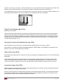
PIPER Wing Tips
I have noted several requests from the ICS members for information on standard Piper−like tips which are made of
fiberglass. Many tips come bare with the nav light holes, but without wing screw holes and the tinnerman back plate for
Chapter 8 – Airframe
3 of 53
the nav lights. So if you order, you should order a tinnerman nut plate also. Although not the same as the original, I still
believe the Met−Co− Air tips are better looking, probably more efficient, and they cost $55 per tip.
Nose Wheel Alignment
It is most important that the ground and flight rigging of your Comanche complement each other. Does your aircraft
become decidedly "squirrelly" or skip and swerve at the transition period of ground run to full flight? This would be noticed
more likely in a no wind still air situation where you would expect a smooth transition into flight. If you do not attain this
expectation it is likely that your aircraft is not rigged correctly. It is most desirable that your aircraft runs straight down the
runway with all the wheels and the rudder in line with the longitudinal center line of the aircraft. As the flight surfaces
become effective they should not be not trying to force the aircraft in one direction while the pilot is trying to steer the
aircraft in a straight line down the runway.
The first step in ground rigging the aircraft is to jack the aircraft and get it horizontally and laterally level. We start by
getting the nose wheel to run a true line with the center line of the fuselage. The important thing to note is that the nose
wheel of the Comanche does not set on the true center line but sets to the right hand side somewhat.
There are two methods of aligning the nose wheel. One is to use a jig which is especially fabricated for the purpose; the
other is by the chalk line and plumb bob method. As many of you would not have access to the aligning jig, I will deal with
the latter method here.
With no load on the nose wheel check the clearance of the steering rollers to the steering bell crank. These bushings
should rotate with a slight drag and have very little clearance. If clearance is excessive, correct it by fitting the appropriate
oversize roller. These are available in sizes 0.625" D, 0.687" D, 0.812" D and 1.0" D. This cannot be emphasized enough.
It is very important that this clearance between the steering bell crank and the rollers be checked while the airplane is on
the ground with normal weight on the nose gear. “DO NOT ADJUST THIS CLEARANCE WHILE THE AIRPLANE IS ON
JACKS!”
Place a suitable length of bar across the nose wheel tunnel resting on the forward edge of the fuselage skin below the
nose wheel drag link hinges. Measure from the inside lower wall of the nose wheel well on the right hand side 5" and tie a
plumb bob weight to the bar at this point. Measure 0.5" to the right of the rear tie down point and attach a plumb bob
weight at this point. Mark a chalk line on the floor using the plumb lines as reference. You now have the true center line.
With the rudder pedals clamped in the neutral position adjust the steering push rods to align the nose wheel by sighting
down the chalk line. Do not adjust just one rod end but divide the adjustments amongst all four ends ensuring that the
threads do not extend beyond the check holes in the rods.
When you have the nose wheel aligned, adjust the pedal bar angles to 13° aft of the vertical. Measure 20° either side of
the chalk line, a line intersecting with the nose wheel contact center point on the floor. Check that the nose gear turns 20°
left and right but not more than 25°. If it turns more than 25°, check for broken steering lock stops on the nose gear
housing. Allowing travel of more than 25° causes the rudder stops to contact and strains the cables and pulley
attachments. Having done this the rudder cables will have to be re−tensioned. In the next issue I will cover the alignment
of the rudder and main wheels with the nose wheel.
Fasteners
I recently replaced all the Southco fasteners on my '65 PA−30 cowlings and another mechanic I learned the following tip.
Since the slot in the fasteners is actually concave, you can get a much better grip on them if you dedicate a proper size
screwdriver and grind the blade so that it has the same concave shape as the Southco fasteners. This should reduce their
deformation ("boogering" them up) considerably.
Chapter 8 – Airframe
4 of 53
Twin Rudder Seal Strip Replacement
Regarding the airflow modification kit, P/N 76C−409 which was installed on most PA− 30's, at the recommendation of
NASA, to improve Vmc and stall characteristics. An essential ingredient in the kit was the rudder seal strip, a rubber strip
which was inserted in the gap between the trailing edge of the vertical stabilizer and the leading edge of the rudder.
The purpose of the strip was to prevent airflow from the high pressure side of the rudder, through the gap to the low
pressure side, thus increasing the effectiveness of the rudder during single engine operation.
We are finding that the original rubber strip, due to the ravages of time, repainting, etc., have deteriorated on many aircraft
and unfortunately the strip is no longer available. Knots 2U, Inc. has the FAA / PMA approval under STC #SA516GL to
manufacture and install Teflon coated aluminum rudder seals which meet the FAR requirements for the PA−30. The seals
not only limit the flow of air through the gap, but they do a better job aerodynamically than the rubber seal.
Cowl Assembly
Another piece of information is that the cowl assembly P/N 22039−02 that you mention in the January Flyer is available in
fiberglass from WagAero of Lyons, WI. This is an exact replica which they sell for the Skybolt homebuilt.
Comanche Airframe Age
Q. How Old Is Old?
I would like to have comments from your readers who have considerable time on their 400 Comanches. Our 400,
N8509P, will soon have 3,000 hours on the airframe. We are noticing some slight airframe changes, such as paint coming
off of some of the rivets on the leading edge of the wings, and a slight buckling on the bottom part of the fuselage in the
spar area. We would like to know if there are other 400's being flown which have as many hours on it as ours and if any of
these similar problems have developed. Our engine was majored at approximately 1,800 hours and the new mags were
installed. We also installed new vibrators and upgraded all of the wiring. Since that time, the 400 has never failed to start.
Except in very hot weather or when the engine is very warm, it will start on the second or third blade over similar to the
250 and 260 Comanches.
We are quite concerned, probably like most 400 owners, that our bird is getting old and that there is absolutely no
replacement for it.
A. Nobody knows yet how long a Comanche airframe will last. I know of some with 8,000 or 9,000hours on them that are
still very sound. All Comanches were manufactured with a coating of zinc chromate on the inside of all metal surfaces, so
you don't have to worry about serious corrosion from the inside. (The same is not true of all Piper airplanes, or Cessnas or
Beeches). As for the paint around the rivets, I have been involved, with the factory, in an in−depth study of the problem.
We found that a strictly minor corrosion around the rivets causes the problem. We find it on other aircraft, too, of course.
When the paint was stripped, the area was cleaned and alodyned and repainted, the problem was solved.
The buckling on the belly doesn't sound at all serious, and it is hard to say what caused it. The spar has no attach points
on the underside − only on the side of the fuselage, so this doesn't indicate spar trouble. This same buckling problem
occurs on new aircraft, so don't worry about it.
You should be glad you have that zinc chromate inside the metal surfaces. I once saw an early model Bonanza on which
the wing had corroded from the inside so badly that you could pry the rivet heads off with a pocket knife. When we
discovered this, the pilot, who happened to be an FAA man, turned green and decided to walk home.
Chapter 8 – Airframe
5 of 53
Flaps
Flap Maintenance
The key to having flaps operate properly is first to clean the tracks and leave them dry. Lubricate the roller on its pin, but
do not get any oil on the tracks as this would certainly collect dirt and probably stick in the extended position in flight. After
regular cleaning and lubricating the rollers, the following will probably keep you out of trouble:
1.
2.
3.
Use no more than 15 degrees for take−off.
Use no more than 15 degrees for landing until you are absolutely certain that you will not have to go around.
After take−off, "milk'' the flaps up a little bit at a time and stop at the first sign of any tendency to turn or roll. Five degrees of
misalignment can be handled easily while fifteen degrees takes full opposite aileron.
Because drooping ailerons go with the flaps on a Robertson Stol Twin Comanche, they are currently placarded by AD to
fifteen degrees max for take−off.
If cleaning the tracks and lubing the rollers doesn't solve your problem, check the retract springs to see that they are
hooked up and not broken. Flaps are retracted by springs only and not by the flap motor.
Flap Maintenance
When flaps fail to retract properly, the retraction spring may be weak. On my 1962 Comanche, the flaps would not retract
all the way on the ground. In the air, there was never a problem! The air loads on the flaps are such, that the flaps are
always returned into the up position.
The flap retraction spring (Part No. 83302−40) are in most older airplanes the original, and have very little tension left! "B"
model Comanches used a stronger spring (Part No. 83302−54), the same as on the Twins. Replacing the spring will
usually prevent a flap hang up.
It is also advisable to lubricate the flap drive, under the rear seat. I have seen some very dry ones
Flap Maintenance
Dupont Slip Spray 6611 is called for in the Piper Service Manual for lubrication of flap rollers and tracks for aircraft with
metal flap rollers. Rollers and tracks on aircraft with nylon rollers require no lubrication. Dupont has discontinued
production of the 6611 lubricant, but a direct replacement is now available from Av−Pac. Order Av−Pac Part No. 60133,
Teflon Dry Lube, $6.17.
Earlier model PA−24−180 and PA−24−250 manual flap hinges call for standard MIL−L 7870 lubricant.
Rigging Manual Flaps
As many Comanche owners are already aware, their particular airplane may seem to fly Chinese style: "One Wing Low".
That is, it will fly this way unless the pilot maintains a slight but constant pressure on the control yoke toward the opposite
side, until fuel burn sufficiently alters the lateral loading. Usually this shows up as a left wing low tendency. Most pilots
tend to compensate for this by using fuel from the left tank(s) first so as to equalize the lateral weight distribution with time.
Another way during flight is to adjust the aileron trim, provided the aircraft is equipped with remote electric aileron trim
capability such as with the "Aerotrim." However, for Comanches not so equipped, the only recourse is to re−adjust the
fixed tab on the aileron(s). Trouble is, this tab does not readily take to resetting more than a couple of times. And, of
course, it cannot be altered in flight or for different conditions prior to flight each time.
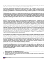
The Problem:
Chapter 8 – Airframe
6 of 53
My 1959 Comanche was no different and for years I flew it this way, keeping a slight roll pressure on the yoke. And since
1986, I had used the handy Aerotrim to keep the wings level while the ball was centered.
But what really disturbed me was the observation that with the wings level in flight, the left aileron seemed to ride much
lower than it should have for the amount of rise in the right aileron, even considering that they are designed to operate
differentially (more displacement on one aileron than the other, to help compensate for the effects of adverse yaw). And
by moving the yoke to cause the left aileron to line up with the trailing edge of the wing, the other aileron was not lined up
properly, and visa versa.
This indicated that either the ailerons, their control system or the flaps were out of proper rig or maybe all were. (Note: It is
sometimes common practice to adjust the zero setting on one flap slightly different than the other flap to help compensate
for a rolling tendency. I did this with my Cherokee years ago. But even with this, the ailerons should still match up with the
trailing edge of the wing at the tips). Moving the yoke to line up the ailerons while on the ground resulted in a similar
displacement. Time to re−rig!
The Solution:
Referring to the Comanche Service Manual for the recommended aileron adjustment procedure, it said (as was to be
expected) to set each aileron so that its trailing edge matched (lined up with) the trailing edge of the associated flap when
in the fully retracted position. Obviously, since mine didn't, it required that the rigging of the flaps be checked first. But the
manual does not state where the flaps should be when in the zero degree, fully retracted position! It just uses the word
"neutral," whatever that means. Remember, this is for the manual flaps that are on all 180 Comanches and on all 250
Comanches up through S/N 2843, model year 1961. (After that time, with the exception of any 180's, all Comanches were
typically equipped with electrically operated flap systems. Manual flaps: are constructed differently with eight ribs
compared to eleven in the electrically operated ones; are driven by a control rod at the inboard end rather than at the
middle; and are hinged below the centerline to achieve some Fowler type action to an otherwise plain flap in comparison
to the semi−Fowler action provided by the later type which rides aft, as well as down, on a rollered track. Furthermore,
manual flaps operate in three settings of approximately nine degrees each to a maximum deflection of 27 degrees.
Electric flaps have no pre−set stops and go to a maximum of 32 degrees on the 250 and 260, and to 38 degrees on the
400. Adjustment tolerances are +/− 0 degrees at the zero (neutral) setting and +/− 2 degrees for the manual flaps and +/−
1 degree for the electric flaps at the maximum deflected position).
One could assume several possibilities for the initial zero degree flap setting position, but logic indicates that it should be
the same as for the electric flaps, even though the manual doesn't say so. At my request, Maurice Taylor asked the
factory. But while they couldn't provide an updated procedure, they indicated that my assumption was okay. This, as is
stated in the manual for the electric flaps, is a 13 degree difference between the upper surface of the flap at a designated
point and the longitudinal level line at the fuselage level points. This works fine, but be aware that the designated point on
the electric flaps doesn't exist on the manual types due to their different construction. But since the shape is the same (or
should be), a point anywhere along the flap should be the same. Just be sure you place the measuring level on an
undistorted surface, the best being immediately adjacent to, but not on top of a rib rivet line. Check several places, on
both flaps, and use a spot that is most consistently representative of both flaps.
If a "bubble protractor" type level is not available, one can easily be constructed. Simply buy a 6" plastic protractor and a
6" plastic rule and attach them together with a small screw at the center point of the protractor. Then attach a small
"pocket string level" to the edge of the rule. Thus, by moving the rule around the protractor's center attachment point, one
can read angles to less than one degree accuracy. The bubble, of course, determines the level reference point for the
assembly. Make sure that the bubble is parallel with a straight line on the rule that is scribed through the center hole and
use this line for reading the angles.
Procedure:
1.
2.
3.
Chock the aircraft so it won't move; open the cabin door and climb in and out several times to cause the aircraft to
settle in a position that won't change while working on it.
Remove the rear wing root and wheel well fairing strips from both wings.
Clean the flap operating bell crank assemblies and install (if not already there) flap stop plates on both bellcranks.
(Piper Kit 754−413 per SL−360).
Chapter 8 – Airframe
7 of 53
4.
Back out both leveling screws on the side of the fuselage above the baggage compartment door (about 3/16") and
place a straight−edge across these screws. A carpenter’s framing square is good for this as it easily remains in
place.
5. Place the protractor on this straight edge and rotate the ruler with bubble level until the bubble is centered. Record
the angle indicated on the protractor for reference (mine was 6 degrees).
6. Then after determining the appropriate measuring place on the flaps as described previously, place the protractor on
the flap (fully retracted) and again adjust the rule until the bubble is centered. Record this reading. Do the same for
the other flap.
7. These retracted flap readings should equal the leveling point reading, plus the requirement of 13 +/− 0 degrees. If
not, the flap(s) must be adjusted.
8. To adjust the flap, the control rod must be either shortened or lengthened by rotating it. Unfortunately, there is no way
to get any type wrench on the holding nut at the forward rod end bearing. This necessitates removing the bolt from
the rod end bearing at either end. I found the inboard end the easiest and once loose, it took only 1 1/2 turns of this
rod end bearing to change the zero flap setting by the one degree mine required. Just be sure to note the placement
of washers and don't let the flap swing free when the bearing is detached. It may take more than one try, but the bolt
has to be reinserted each time. Adjust both flaps as necessary.
9. Place the flap handle in the flap fully extended position and again measure the flap deflection angle with the bubble
protractor as before. The difference between this reading and that at the leveling point should be 27 +/− 2 degrees.
10. If not within these limits, or if fine tuning is desired, adjust by altering the length of the control cable. This is done
separately for each flap via the turnbuckles under the rear seat. There is one for each side, aft of the juncture with the
common cable from the flap handle. After adjustment, ensure that both turnbuckles have no more than three threads
exposed on each side and that they are properly re−safetied by using new safety wire with at least four turns around
each shaft.
11. Retract and re−measure the angular setting of both flaps. Then, if desired, set the flap handle to each of the other
settings and measure both flaps. Intermediate settings should result in near 9 and 18 degrees (after subtracting tare),
but may vary from this due to wear of the notches in the flap handle ratchet. It is not critical and both flaps should be
similar. Record all measurements for future reference.
12. Lubricate if necessary. But before replacing the wing root fairings, adjust the fillet between the wing root and fuselage
so that it lines up perfectlywith the wing. This fillet is attached at both the side and forward ends by screws with
captive nuts through slotted and access holes. The flaps must be fully extended to access the side hole.
Observations:
It is interesting to note that when the control rod end bearing is detached from its bellcrank bolt, the flap is free to swing
from above its zero reference to almost vertically down. Attempts to give just a little more flap extension will be to no avail
since at the +2 degree tolerance limit, it is the rod end bearing bolt that touches against the flap load spar, not the rod or
any part of the flap. So I set mine at 28 rather than 27 degrees, which was still within limits and allowed some clearance.
Since cables do stretch after a lot of use, and flap rigging is necessary prior to aileron rigging, it is probably a pretty good
bet that every manual flap Comanche needs this type of attention if it hasn't been properly done for some time. It is easy
to do by one's self by following the above procedure. I also recommend that the opportunity be taken to ensure that the
flap up−locks on both sides are in good condition and are adjusted properly. See SL−360 for additional references.
The procedure for adjusting the electric flaps is similar as to the use of a bubble protractor but, while the procedure is
outlined in the Service Manual, it is a little more complex due to the use of limit switches and indicator.
Chapter 8 – Airframe
8 of 53
Flap Alignment
Another simple item to check and maintain on both the single and twin is flap alignment. With electric flaps there is no
connection to keep both left and right flaps "in line" at all times. Should one flap not retract fully (even within a "half inch"
of full retraction) after take off it will take full opposite aileron to maintain level flight. Luckily when you throttle back and
lower flaps to land, things straighten out and you wonder what happened.
The two measures to prevent this would be to keep the flap "slotted tracks" super clean, but not oily, as this would pick up
dirt. Also, on run up make sure you cycle flaps to note they retract fully on both sides.
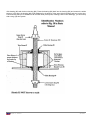
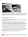
Flap Maintenance
For those of you with manual flaps, the system can wear enough such that sooner or later you'll try to lower flaps and they
won't come down. Of course "Murphy'' will make this happen as we set up for a short field landing at our favorite fishing
hole airport!
The manual flap system has a ''tongue'' that pushes a locking pin out of the way so that the cable tension (via your arm)
can lower the flaps. Eventually the tongue will wear enough so that it doesn't push the locking pin completely out of the
way and voila − you have flaps locked in the up position! Of course, removing the assembly, cleaning and new lubrication
is desirable on a periodic basis.
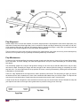
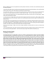
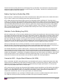
There is a "stop" adjustment for the tongue that is: held in position by two screws. This stop faces you when you remove
the wheel well liner and is located on the front of the mechanism that rotates when you lower the flaps. The flap rod end
connects to this mechanism also. Simply loosen the two screws and remove the stop. It looks like this:
A small rat−tail file can elongate the holes somewhat so that the stop can be slid further inboard. Reinstall the stop and
your flaps will now lower as the tongue has a greater travel to push the locking pin out of the way.
Chapter 8 – Airframe
9 of 53
Flap Maintenance
Older Comanche flaps were mounted using steel bushings, which were eventually replaced with P/N 26343−00 nylon
bushings. The steel bushings vibrated on the aluminum tracks and wore a widened area in the front of the slot, resulting in
a "sloppy" flap. In extreme cases, you can see the trailing edge of the flap fluttering in flight, I'm told.
I replaced my steel bushings with nylon immediately after purchasing the plane. Nevertheless, my outboard track
assemblies were worn, but not too badly. So when an opportunity arose to pick up a pair of new track assemblies (P/N
23227−03), I did so. However, I was then told by three mechanics that it was a terrible job to replace them − the upper
wing skin had to be peeled back to buck the rivets in the rear spar. In fact, I saw one airplane where they tried to avoid
this by replacing only the aluminum track, by drilling out the rivets holding the track in the steel angles that rivet onto the
rear spar and wing skins. I agreed that that was a terrible job, so I didn't replace the tracks.
Until this year, that is, when intergranular corrosion was found in the left outboard track. My mechanic and I discussed the
situation, and basically prepared for an all−day job of deskinning, etc. To make a long story short, however, by removing
the false spar just outboard of the track assembly, a lightening hole in the rear spar is exposed, allowing you to buck the
rivets easily. Total time for the job winds up being an hour or so, including the removal and replacement of the false spar.
This may be old news to really experienced Comanche mechanics, but it's apparently not universally known, so I thought
I'd pass it along to those dreading replacement of worn track assemblies.
Wing Miscellaneous
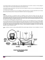
Wing Root Gap Seals
So you say you want to put on new wing root gap seals? So you pull out the old one real easy and get the feeling that
Piper put the seal on before they put the wings on the fuselage − you're right. Then you get the uneasy feeling that putting
on the new one will be tough − you're right again. But there is hope.
The seal is a four flange seal. Two flanges grip the wing skin and two lap against the fuselage, one up and one down.
Don't despair. Go have a good Chinese dinner and save the chopsticks! Chinese chopsticks, the round, smooth kind, will
help quite a bit. Now get a big tie wrap, i.e., one that is about 3/8 inch wide and 12 inches long. You are now armed with
the tools to do the job. Lubricate the side of the fuselage with WD− 40 or Teflon lightly. Just make it a little slippery.
Now, place the seal in the proper alignment above the wing skin and lower it till the flange that will be under the wing
touches the top of the wing and bends slightly. Keeping pressure on the seal from above, tuck this flange back toward the
fuselage with the chopstick until you see it flip underneath the wing. Do this only for about a 2 inch span. Then, keeping
pressure on the seal at this point, begin tucking the flange (with chopstick) that will point downward and lap against the
fuselage. Simply force it to bend on itself and fold against the fuselage. It will now be in a "U" shape against the fuselage.
Then, using the tie wrap end, force the flange to snap down in position underneath the whole seal. You can move the
whole thing up and down gently with the big end of the chopstick and a peek underneath (remove fairings) will confirm the
correct position. Cut off bottom pieces of seal where it goes over wing spar. Have patience and you'll get it eventually.
Chapter 8 – Airframe
10 of 53
Ailerons
Aileron Cable Separation by Corrosion
I had a call to report a broken aileron cable. This happened during a period of strong, gusty winds, but fortunately, while
the aircraft was on the ground. His plane was parked outside with the control wheels tied together to keep the ailerons
from going from stop to stop. A call from the airport alerted Ed to the fact that the ailerons were banging back and forth.
His examination showed a broken aileron cable which was rusted in two just aft the wheel well area. This should have
been discovered more than one annual back.
At the seminar in Hamilton, Ontario, an A.M. engineer brought with him an aileron cable which was eaten almost in two.
As I remember, he found this on his first inspection of a member's aircraft. Again, this should have been found prior to that
inspection.
It is my feeling that we have three areas which are most susceptible to cable corrosion. These are just aft of the wheel
well, between the wing and fuselage and under the floor near insulation which may get wet and is therefore slow to dry
out.
Inspecting an airplane properly is no easy job. It takes time, alertness and dedication on the part of the person running the
inspection.
Aileron Adjustment
Last year, I published an article describing the problem and an appropriate procedure for adjusting the flaps on a
Comanche. ("Rigging Manual Flaps"). As noted in the article, what brought this on was a condition that always seemed to
result in the ailerons being displaced from their proper streamlined position while in flight; re−rigging was required. But the
problem in doing so, and what made this article so important for other members to be aware of, was that the aileron
adjusting procedure, as outlined in the Piper Service Manual, started off by stating that one should first align the ailerons
with the flaps at the trailing edge. Thus, one had to adjust or ensure that the flaps were properly rigged first. But,
unfortunately, the manual didn't include a sufficiently detailed procedure for such rigging on an aircraft equipped with
Chapter 8 – Airframe
11 of 53
manual flaps; only for those equipped with electrically operated flaps. My article describes an appropriate procedure for
rigging manual flaps.
For general interest, manual flaps are incorporated on all PA24−180 model Comanches, regardless of model year, and on
all PA24−250 models up through s/n 24−2843, model year 1961. After that time, with the exception of the 180's, all
Comanches were typically equipped with electrically operated flap systems. Manual flaps are constructed differently with
eight ribs compared to eleven, are driven by a control rod at the inboard end rather than at the middle, and are hinged
below the centerline to achieve some Fowler type action to an otherwise plain flap in comparison to the semi−Fowler
action provided by the later type which rides aft, as well as down, on a rollered track. Further, manual flaps operate in
three settings of approximately nine degrees each to a maximum deflection of 27 degrees. Electrically operated flaps
have no pre−set stops and go to a maximum of 32 degrees on the 250 and 260, and to 38 degrees on the 400.
So, once the flap systems are correctly rigged, as outlined in my article for manual flaps and in the service manual for the
electrical type, THEN one can proceed with aileron rigging. The procedures are outlined in the service manual and are
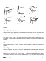
applicable to all model Comanches. But a few hints may be in order. It is first necessary to construct the gauge used to
set the aileron bellcrank control rod. The dimensions for this gauge are shown in the service manual. It can be easily cut
out of stiff, thin cardboard or aluminum sheet. I used cardboard. The same gauge is used for both wings; simply turn it
upside down for the opposite wing, and save it for future use.
With the gauge in place and the bellcrank positioned as shown in the manual, remove one end of the control rod and,
through trial and error, adjust its length so that the trailing edge of the aileron aligns with the trailing edge of the retracted
flap. Next, using a bubble protractor similar to that described in my previous article, adjust the aileron bellcrank stop bolts
to achieve the aileron up and down travel limits described in the manual for the specific model type. (180/400's have
different tolerances from 250/260's.)
Then, with the ailerons externally clamped in neutral position (welding or wood gluing clamps similar to large clothes pins
are handy), adjust the two cable turnbuckles attached to one of the bellcranks to achieve proper cable tension and relative
aileron position (the clamps will have to be removed for each trial adjustment in order to gain access to the turnbuckles as
it's a tight fit for most people's hands). Typically, these two turnbuckles must be adjusted by tightening one and loosening
the other so that both ailerons align with the trailing edges of their adjacent flaps simultaneously. One of these cables is
routed to the control column in the cockpit while the other is routed to the opposite bellcrank.
Then, when this has been achieved satisfactorily (note the caution in the manual procedure), re−clamp both ailerons to
align with their respective flaps and adjust the turnbuckles on the control cables inside the cockpit (above the pilot's rudder
pedals) so that both control yokes are in proper neutral (level) position. The co−pilot's yoke can be made to match with the
pilot's yoke by separately adjusting the two turnbuckles associated with the cross−connecting chain between them. Proper
tension will also remove any sloppiness that may have previously existed. Later model 260's and all 400's are also
equipped with an aileron−rudder control cable interconnect system. A separate adjustment must be made on these
aircraft to set proper spring extension per model (see manual).
Also, check to ensure that with full aileron deflection, both up and down, the bellcrank of one aileron goes against its stop
simultaneously with the opposite stop of the bellcrank for the other aileron, and vice−versa. Do this before safetying the
turnbuckles.
If your turnbuckles are the type that uses the small wire clips instead of the often very difficult to wrap safety wire, these
can be easily removed by prying off from the center hole in the turnbuckle with a screwdriver or pliers. If done with care,
they can be re−used after re−shaping. Note, however, that the slot the wire clip slides into exists on both sides of the
barrel at both ends, as indicated by little notches, but is only along one side of the screw portion. This side is marked by a
small indentation of the edge of the eyelet. This allows for half−rotation adjustments but is important to observe
beforehand, or you may end up spending hours trying to insert the safety clip where there is no slot! Finally, be aware that
control surface adjustments are not part of authorized owner preventive maintenance. Work under the guidance of your
cooperating mechanic or inspector as he will have to ensure that the adjustments are done correctly, safetied, and make
the appropriate logbook entry. Then, go out and fly straight and level for a change!
Chapter 8 – Airframe
12 of 53
Engine and Cowling Controls
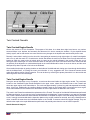
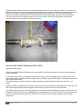
Twin Cowl Flap Control Cable Replacement
By David R. Clark ICS 08592 A/P
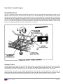
As you may notice, practically nothing of what I'm going to tell you is in the Twin Comanche Service Manual. Recently, at
the end of a beautiful flight to Fayetteville, AR, I pulled on the cowl flap controls only to have the left one come out about
three extra inches. This, I soon found out, was due to the cable breaking off just proximal to the attachment bolt, just in
front of the firewall. Because of the spring mechanism, this automatically returns the cowl flap to the closed position. The
next day back at home base, I discovered that the cable with the handle still attached to it will remove easily from the
housing by simply pulling it out through the panel side. A conversation with Maurice Taylor confirmed that a new cable
could usually be fed back in through the same route. This greatly relieved my fears, as I had envisioned having to tear the
floor out, etc., to replace the entire cable assembly.
Here is the drill:
Establish that you have a broken cable. Remove the left side engine nacelle (it's on the left side on both engines). See
where the cable comes out of the firewall and attaches to the cowl flap control mechanism. It's obvious if it's broken.
First, locate a suitable replacement cable insert. I could not find anybody selling this part separately, and Av−Pac tried to
locate one also, without success. Even they realized their price of $196 for the whole assembly seemed too much for what
I needed. Again, Maurice Taylor to the rescue. He located a cable assembly at Dallas Air Salvage, which is about a 30
minute drive from my hangar. A very knowledgeable fellow named Lucky had 8 or 9 of the cables and lots of good advice.
He wanted $55 for one of these used cables (which was the whole assembly).
Next, remove the cable insert from its housing on your "new" replacement cable and don't lose the small ball bearing
which is the friction lock. Clean off the cable and gently straighten out any kinks at the end. Don't cut into it with pliers, as
it is fairly soft material. Now, file the tip to make it rounded so it will pass easily through the housing. Finally, lubricate the
wire with silicone lubricant or the like. Remove the old broken cable from its housing, but don't discard it (more about that
later). Next, push the new cable through the opening in your panel and gently, but firmly, coerce it the twelve feet or so out
to the engine. Occasionally, you'll have to twist or rock it in and out a little to get it all the way. If you hit a snag just when
you think you are almost all the way through, take off the inspection plate at the top of the engine nacelle, just above and
behind the fire wall. Loosen the clamp that holds the cable housing and pull the housing back into the rear compartment.
This will straighten it out enough to let the wire pass the final sharp curve. Once the cable is through, replace the housing
back in place and tighten the clamp. Here is the only place the manual tells you how to adjust the housing clamp. See
page 2D23 in service manual. Make sure you re−install the tiny ball bearing friction lock on the handle as you push it the
last few inches into the panel.
Now loosen the bolt where the old broken off piece of cable is still attached. Remove this and insert the new cable. Again,
be careful not to over−tighten, as this acts as a guillotine and can cut the cable. (Warn your A&P about over-tightening
this bolt.) Make sure the cable is straight when the cowl flap is in the closed position, because if a slight bend or bow
exists, it will gradually break, just like mine did. Here is a good time to inspect the cable on the opposite engine. There
was a bow on my other cable which I took out by adjusting it.
Make sure the return spring is still on the cowl flap mechanism. Also check this at annual time. If one of your cowl flaps is
much harder to close than the other, it is usually due to the spring breaking or because it is missing.
A really enterprising person could get a piece of piano wire of the same diameter as the cable and "sweat" the old wire out
of the handle and replace (solder it back in) it the same way. If you do this with your old cable, you'll have a spare.
TWIN COWL FLAP CONTROL CABLE REPLACEMENT
Having just read a recent issue of the Flyer about replacing the cowl flap control cables on the PA−30, I thought I would
suggest an easier way than he encountered.
Chapter 8 – Airframe
13 of 53
Mine is a 1964 PA−30, and I have replaced both cowl flap cables. One broke, and I had to solve the dilemma quickly and
as cheaply as possible.
I removed the old cables from the aircraft by disconnecting them forward of the firewall and pulling on the cowl flap handle
inside the cabin until the entire cable had been removed from the cable housing.
I then placed each handle in a vice and heated the tip with a blowtorch, pulling on the cable, until the wire separated from
the handle. (The original installation has the wire crimped inside the handle − you have to pull hard and sweat it out).
Then I visited a good hardware store in my area and bought (for about $5) a roll of piano wire of the same gauge. I visited
another store and bought silver solder.
I cut the new wire to a length about a foot longer than the length of each wire removed (for a safety margin) and then
silver soldered each piece into the handle, using a vice to hold the handle in place and silver solder to hold the wire in the
handle securely.
I then fed the wire into the cable housing in the aircraft with pliers in my right hand, feeding the cable six inches at a time
(lots of hard effort), and applying grease with my left hand as it went in to the housing. I didn't need to remove the top of
the nacelles as David did − I simply applied the effort on the pliers at the entry to the housing and with the benefit of
lubrication, the cable went through, even around the last turn through the firewall.
Once all the way through, I simply cut the wire to length, screwed the cowl flap holder to the wire, and the job was
completed.
Total cost was about $20 or less, and the total time was about three hours (excluding the driving around to stores). By the
way, do not try this with regular solder − it won't hold it securely enough. Silver solder is the only way to go.
Binding Throttle Cables
Ivan Warrington, ICS #08405
The Gremlins have been at it again! After a recent trip to Lubbock I noticed that all the controls on the throttle quadrant
were binding abnormally. I concluded that it was due to the 23° overnight temperatures in Lubbock. Upon return to Dallas
I tubed all the cables (discussed in a later article) and they were still binding. I was sure that I was about to install new
cables. Before this drastic measure was taken it was time to go to the mountain and talk to the Guru. He told me that the
hollow tubes at the engine end of the cables were bent! Say What? What barrels? Here is how to find out if your cable
barrels are bent. Push all control levers forward. Start at either engine, any control. Try to turn the barrel it should rotate
easily on the cable. Now move control to mid position and try again. The barrel should turn as easily as it did before.
We're almost finished. Now move the control to rearward position and turn barrel. Did it turn as easily as the first two
times? It did, well it ain't bent. Repeat for each control. Did the barrel bind in any of the positions? It did, well it's bent. For
repairs to be made the cable will have to be disconnected from engine. Be sure not to move the turnbuckle. Place the
barrel on a short piece of two−by−four or anything straight and turn to find the high side. Take a hammer and slightly tap
the barrel to straighten. Now try the cable in all of the fore mentioned positions, better huh? How did the barrels get bent
in the first place? Well I'm going back to the mountain real soon to find out. Gremlins maybe!
Chapter 8 – Airframe
14 of 53
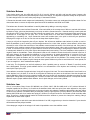
Twin Cracked Firewalls
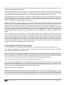
Twin Cracked Engine Nacelle
We are the owners of a Twin Comanche. The purpose of this letter is to relate what might have been a very serious
structural failure in our airplane, but fortunately we discovered it in time to remedy the situation. I fly the airplane almost
entirely myself, and for that reason I am more sensitive to any changes in the airplane than would usually be the case.
Recently I noticed that in taxiing in on the slow idle, I was getting an extremely rough right engine. On careful investigation
and a run−up with the cowls off, I found that the trouble was where the motor mount bolts to the fire wall and where the
bracket to which the motor mount is bolted, which is riveted to the vertical bulkhead in the nacelle. Either due to not
having the motor mount tight or to some excessive strain on that part, as a result of the fact that the motor mount itself did
not perfectly fit the alignment, a crack had developed on the vertical bulkhead for about six or seven inches, and the crack
had opened up about a quarter of an inch at the bulkhead.
We remedied the situation by putting doublers on both sides of the bulkhead and riveting new rivets through both doublers
and the bulkhead itself, re−riveting the motor mount bracket. It is my suggestion that Twin Comanche owners should
make this a definite portion of their inspection. This can be done by removing the square plate which is on the nacelle and
observing with a mirror and a flashlight.
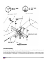
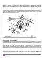
Twin Cracked Engine Nacelle
During the annual inspection on my Comanche, a crack was discovered inside the right engine nacelle. The crack was
located on the Outboard Engine Nacelle Bulkhead in the upper corner, where the bulkhead rivets to the Firewall and
where the upper engine mount frame bolts to. The crack was approximately 3 inches long and had separated horizontally
about 1/2 an inch. Additionally, the resulting vibration caused a crack in the Firewall itself, from where the lower engine
mount frame attaches to the Firewall to the area where the Cowl Flaps bracket is attached to the Firewall.
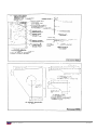
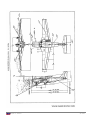
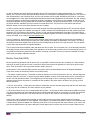
The crack in the Firewall necessitated the replacement of the Firewall. The repair of the Nacelle Bulkhead was performed
by Midcoast Aviation. As you can see by the enclosed analysis, and diagrams, it was necessary to cut away the damaged
area, install a stainless steel filler and a stainless steel doubler to complete the repair. Since this damage was very difficult
to see, I strongly recommended that the inspection plates on the engine nacelles be removed, and using a flashlight and a
mirror, examine the area where the bulkheads fasten to the Firewall. If someone should find similar damage, they can
reference the repair to the repair Midcoast has performed, and possibly save them the cost of a DER inspection.
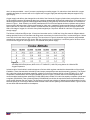
Nacelle Structural Analysis
Chapter 8 – Airframe
15 of 53
Introduction
This report provides the structural analysis for repairs detailed in Midcoast Drawing 60−000R001 "Repair, R/H Engine
Nacelle Structure." The aircraft is a Piper Twin Comanche, Model PA−30.
The damage consisted of cracks found in the outboard nacelle web and on the firewall. The repair replaces the firewall,
and trims out the damaged section of nacelle web.
Analysis
Firewall: the original firewall was manufactured from 0.023 thick galvanized steel. The −9 Firewall is fabricated from 0.025
thick 301 1/2 hard stainless steel. From Jorgensen Steel Handbook, galvanized steel sheet is 15% low carbon steel alloy.
Per Machinery's Handbook, 21st edition, page 2120, the Ftu = 65 KSI max. For 301 1/2 hard stainless steel, per
MIL−HDBK−5D, Table 2.7.1.0(b), Ftu = 141 KSI. By comparison, it is obvious that the 0.025 stainless steel is acceptable.
Nacelle Web:
Approximately 4" x 7.5" section was removed from the web (see −7 Repair Filler). The bulkhead is 0.050 thick 2024−T3
bare aluminum. Per MIL−HDBK−5D, Table 3.2.3.0(bi), Ftu = 65 KSI. The −3 Repair Doubler is 0.063 thick 2024−T3
alclad. Per Table 3.2.3.0(el), Ftu = 59 KSI. The repair rivets are primarily MS20470AD4, per Table 8.1.2. (b) shear = 388
Lbs.
Check −3 Doubler Thickness:
Calculate required thickness: 65/59 x 0.050 = 0.055. The 0.063 thick −3 Doubler is acceptable.
Check Rivet Quantity:
Strength loss for 4" side: 65000 x 0.050 x 4 = 13000 Lbs.
Rivets required: 13000/388 = 33.5 or 34 rivets.
Strength loss for 7.5" side: 65000 x 0.050 x 7.5 = 24375 Lbs.
Rivets required: 24375/388 = 62.8 or 63 rivets.
Total required: 63 + 34 = 97 total rivets.
Examination of the drawing shows this quantity is met. Note that this method is conservative. A realistic method is to
measure diagonally across the trimmed out area. This gives a length of approximately 8", thus: 65000 x 0.05 x 8/388 = 67.
This gives a Margin of Safety = 97/67 −1 = +.44.
Conclusions
It is concluded that the repair detailed in 60−000R001 is structurally sound and acceptable.
Note:
CAR 3.624(b)(1) suggests 0.015 Heat and Corrosion resistant steel to be acceptable. The 0.025 301 1/2 hard stainless
steel meets this requirement.
Chapter 8 – Airframe
16 of 53
Chapter 8 – Airframe
17 of 53
Chapter 8 – Airframe
18 of 53
Seat Rails-Cracked Stringers
Seat Rail Bulkhead
One of our members, Eugene Chiappe, ICS #07578, advises that he found the bulkhead cracked where the plate nuts are
attached, which hold the back end of the seat rails (See "A" on attached drawing.) He made this discovery as he was
changing some insulation in this area. He told me that the previous owner had put in new carpeting and then mounted the
seat rails on top of the carpeting. This allows the rail to move every time a person sits on that seat. The seat rail should
rest on the floor panels with nothing in between. The fix was the removal of the nut plates, the cracks stop drilled, a piece
of 1/2" x 1/2" angle was applied to the full length underside of the bulkhead and the nut plates replaced. I want to thank
Eugene for finding this potential booby trap and calling it to our attention.
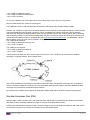
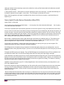
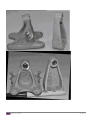
Stringer Cracks
Several members have advised me that they have found cracks on the forward end of the stringer #13 at the point shown
on the drawing on both sides (see page 8 − 20). So far all the airplanes reported have been 260's, but I doubt this is
confined just to this model. Time does not seem to be a factor, as these range from 2,900 hours to 11,000 hours.
On these 260's, the cracks can be located approximately 4" below the air vent at the pilot's and copilot's heels. By
removing the left and right inspection access panels which are under the pilot and copilot's heels, you can use a mirror
and flashlight to inspect this area. See photograph for what you can expect to find if there are cracks in this area.
Chapter 8 – Airframe
19 of 53
This particular stringer on the forward end has a race track shaped hole cut into it which, I assume, is for the passage of
wires, although none of the reported aircraft had any wires through this hole.
As the bottom engine mounts attach to the forward end of these stringers, the load from it is then transmitted back through
the stringers into the fuselage.
So on single engine Comanches, on your next inspection, please check this area. It would be appreciated if you would get
back to me if you find any cracks. This way we can determine if there is an ongoing problem.
Rails
In the March 1992 Flyer, we discussed cracks in the bulkhead under the pilot's and copilot's seat rails, where the
carpeting had been placed between the seat rail and the floor, allowing the seat rail to rock. I had queried Piper about this
and received a drawing from them showing the seat rail mounted to the floor boards with nothing in between. Since then, I
have learned that some of our airplanes may have come from the factory with the carpeting mounted between the seat
rails and the floor. Perhaps this was a cost reduction item.
I am receiving many calls regarding the damage that this is causing. If yours are installed in this way, I strongly suggest
that you get the rails down on the floor boards where they belong and inspect for cracks. Remove whatever is necessary
to do this. But if you do not remove the carpeting from under the seat rails, plan at one of your next inspections to remove
both side panels, take up the floor boards, which in itself is no easy task, and repair the damage. Then install the seat rails
as shown in the drawing and this problem will not reoccur. This will require the completion of a Form 337 and FAA
approval to return the aircraft to service.
I have included an extract from Piper drawing #26652 (See opposite page) showing the correct installation of the seat
rails.
Chapter 8 – Airframe
20 of 53
Stabilator-Balance, Trim, Corrosion, Flutter
Stabilator Balance
I now have a new, more serious problem and a question: It concerns tail flutter in the PA−30. I believe that my problem
was due entirely to CG being too far aft. The tail flutter occurred when the take−off weight was at gross but the back seats
were shifted two notches further back than I normally have them set. Is there any report of flutter in any condition other
than CG too far aft? We are all well familiar with the stories of Bonanza's tails fluttering and coming off. Has this ever been
suspected or known to occur in a PA−30?
When the tail fluttered the horizontal portion of the tail could be seen vibrating up and down rapidly, perhaps 5 times per
second, and the control yoke likewise vibrating at the same frequency in and out, with excursions of about 1/2 to 1 inch
with each vibration − in other words quite noticeable indeed and worrisome to the plane occupants about the possibility of
our losing the entire tail of the aircraft. This entire episode lasted about 10 minutes at 5,000 feet, occurring about 10
minutes after takeoff. In addition, it occurred, less severe, 2 days later, 2 hours into the flight, well under gross weight and
certainly within correct CG envelope, for about 15 minutes. Could I have damaged the aircraft controls enough that one
time that I was out of CG at gross weight to the point, that I will have the problem continuously now regardless of loading
or CG, on an intermittent and unpredictable basis? I would also worry about the concept of metal fatigue and that I might
have an increased chance now of losing the tail suddenly one day.
ED: ICS Technical advisor said we have had a number of calls recently regarding a vibration in the tail (stabilator tip's
moving up and down), in most cases at high speed, however in two at relative low air speed. This is caused basically by
just one thing − the stabilator is out of balance. If the stabilator is painted or repaired it MUST be checked for proper
balance.
All PA−24's, 26's, 30's and 39's were painted with lacquer. If you use polyurethane, it is approximately 20% heavier than
lacquer. There have been some cases where you can not get the stabilator balanced without removing the polyurethane
because of the extra weight. I can not over emphasize the importance of having this checked.
Flutter of the horizontal stabilizer can also be caused by the stabilizer bearing block being loose. See Piper SB 411A and
464, and AD 74−13−01.
Stabilator Balance
After experiencing a vibration, we read of other people's vibration problems in the "Tips Special''. Since we had just had a
paint job, we decided that a stabilator balance check was in order and boned up on the service manual procedures.
No problems until we priced the balancing weights called for. First, you can't find master check weights, (P/N 23584−00),
but that isn't a big problem since the manual gives the weight (1.58 lb.). Second, the balancing weights, (P/N 23179−00),
were quoted at $232 each! Since the manual doesn't give any information on these weights, that could have been a big
problem.
However, a quick call to ICS turned up a complete set of weights at Air Salvage of Dallas ((214) 227−1111) for $30. Two
weights balanced the stabilator nicely, using the service manual procedure.
For information, the balance weights (P/N 23179−00) are 2" x 1 1/4" x 1/16'', with a hole in the center for a close fit on a
#4 bolt. The weights are steel, primed and painted and will weigh about 3/4 ounce each.
While we had the plane on jacks, we adjusted all control cables for travel and tension, adjusted the slide blocks around
the control yoke tube and adjusted the landing gear (the left main was not going quite all the way into the well).
As a result, our Comanche is flying great! We recommend everyone pay attention to the control cable tensions, especially
in the twins, since any slack in the rudder cable will deny full rudder travel.
Chapter 8 – Airframe
21 of 53
Stabilator Balance
I have had a twenty year love affair with the PA−30. It is quick, efficient, well built, and just plain pretty. However, this
gives no license to ignore some plain aerodynamic facts of the design. The airplane will perform exactly as the pilot tells it
to, within design limits. Like some other pretty things, if mistreated it will bite.
A Comanche demands certain respect and understanding. Comanche owners can understand the airplane better if a few
minutes are taken to remove the inspection plate forward of the stabilator and LOOK and THINK.
The balance arm forward of the stabilator is carefully balanced by adding or removing weights.
Static balance of the control surface IS essential. I first was briefed on the consequence of failure to maintain this balance
by Maurice Taylor, who was placed among us to keep us and the Comanches alive. I listened carefully to each word and
went directly to Bill Turley's shop for work that I did not trust myself to do; then I went out and nearly killed myself and my
Comanche on a test flight to Vne plus 10%. A few words need to be said about Comanche airplanes at speed
approaching or exceeding Vne. I hope Comanche owners will consider them in the spirit in which they are presented.
Keeping alive is high on our list, for how else can we keep these airplanes flying?
I hope you will pull the inspection plate off your airplane. We will assume stabilator static balance is perfect as can be.
Move the stabilator up as for entering a dive and again down as for a climb. Now, position it about where it will be when
trimmed for cruise. Notice that movement of the stabilator causes related movement of the linked trim tab. If the plane is
trimmed for cruise, positive pressure will be required at the control wheel to enter a dive, and you will have to pull to make
it climb. The amount of pull or push you exert relates to amounts of force necessary to change angle of attack of a surface
in aerodynamic balance for level cruise flight at that airspeed and power setting. This force translates to either positive or
negative loads on the stabilator. These aerodynamic loads are not in balance unless the aircraft is trimmed in and out of
each pitch change. At low speeds the imbalance is of no importance. At speeds approaching or in excess of Vne, the
aerodynamic imbalance produced by forced pitch changes from the trimmed position is far in excess of any static
imbalance we check the balance arm for, and will result in heavy buffet of the stabilator. The message comes through
loud and clear: Trim the airplane for pitch change at these speeds. Make every effort to avoid this never−never speed, but
if you are caught in it, don't manhandle the airplane.
I was lucky. The Comanche is a well built airplane to which I probably owe my survival. A "Brand X" most likely would
have disintegrated. This high speed stabilator buffet is not characteristic of the airplane and ordinarily is induced by
control pitch input by the pilot.
I have talked to a number of people who have "enjoyed" the type of ride I had. The worst characteristic I have found is not
in the airplane, but is in those of us who fail to recognize the loads we can place on the airframe. Note the drooped and
warped stabilator, failing from heavy negative loading and heavy buffet from aerodynamic imbalance produced by high
speed pitch change without corresponding trim. We have to learn from these shared experiences. Vne speeds demand
absolute respect, proper stabilator static balance, trim for pitch changes, and no heavy hands.
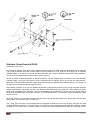
Stabilator Jam
One of our members, Barry Canner ICS #06049, has a PA24− 260C, S/N #24−4989, built in 1971 with an Altimatic III
Autopilot installed at the factory. He found that the stabilizer bridle cable was quite loose when adjusted to the proper
tension of 17+ 2 lbs. He discovered that due to the servo location, this raised the stabilizer cable allowing the back clamp
to catch on the stiffener or bulkhead. Barry checked with Century Flight Systems ( formerly Mitchell ) and found that their
drawing #69−D508 calls for a bracket and pulley #7−A598 to be mounted under the floor board to hold the bridle cable
down, as well as a football shaped bracket #7131068 around the stiffener to prevent the clamp from catching. Barry's
airplane did not have either in place.
If you have a single or twin which came with the Altimatic III or IIIB, I suggest that you check to determine if yours has the
two brackets and the pulleys installed.
If the clamps get caught on the stringer it will make it impossible to move the stabilizer control.
Chapter 8 – Airframe
22 of 53
Stabilator Attachment Hardware
In the February '93 Flyer, I talked about the importance of checking the stabilizer for looseness. In the process of making
this inspection, several alert mechanics, one of whom is Dave Pratt, the IA inspecting Dick Cameron's (ICS #07109)
aircraft, reported finding various problems.
1.
2.
3.
4.
The two bolts, item #1 on the drawing, which are AN175− C33A, Piper #502−343, for the 180,250 and 260 and AN175−33A,
Piper #402−346 for the 400 and PA30/39, which hold the stabilizer horn to the stabilizer tube, were badly rusted where they go
through the inside of the tube.
The one bolt, item #2 on the drawing, which is AN174−22A, Piper #402321 on all models, which attaches the stabilizer horn to
the stabilizer balance weight tube, should also be checked.
The two bolts, item #3 on the drawing, which are AN24− 46A, Piper #400−932, that attaches the collar to the torque tube, were
also badly rusted where they go through the inside of the tube.
The four bolts, item #4 on the drawing, which are AN1 74− C32A, Piper #502−329 for the 180, 250 and 260 and AN175− C32A,
Piper #502−342 for the 400 and PA30/39, were changed to corrosion resistant bolts IAW Piper S/L 667A, dated 3/4/74.
The bolts removed from Mr. Cameron's 180 were AN175−33A (noncorrosion resistant) bolts. The parts book now calls for
AN175−C33A (corrosion resistant) bolts in the 180, 250 and 260, but not specified for the 400 and the twins. I sent a
request to Piper that this be changed, and they have now advised me that the bolts can be interchanged, so use the
AN175−C33A on both the 400 and the twins.
The torque tube on this aircraft was also badly rusted. I cannot over emphasize the importance of checking these parts,
and I have been informed by Piper that NO corrosion is to be allowed.
To identify the bolts, see the drawings below:
Also see FAA Special Airworthiness Information Bulletin #CE-04-88 dated 9-15-04. Also ICS member Hans Neubert is
doing extensive research on this subject.
Chapter 8 – Airframe
23 of 53
Stabilator Inspection
From the desk of Maurice Taylor Note: Also see FAA Special Airworthiness Information Bulletin #CE-04-88 dated 9-1504. Also ICS member Hans Neubert is doing extensive research on this subject.
We have talked about the inspection of the empennage in the past, but I think that we should remind you again regarding,
this important inspection. If the stabilizers on your aircraft haven't been taken off to inspect the torque tube and bolts, I
Chapter 8 – Airframe
24 of 53
strongly advise that you have it done at the next annual. We have found bad bearings, rusty bolts, and rusty torque tubes.
Piper doesn't allow any corrosion on this tube. Be sure that you have the corrosion resistant bolts installed as shown.
1.
2.
3.
4.
The two bolts, item #1 on the drawing, which are AN175− C33A, Piper #502−343, for the 180, 250, and 260, and
AN175− 33A, Piper #402−346, for the 400 and PA30/39, which hold the stabilizer horn to the stabilizer tube were
badly rusted where they go through the inside of the tube.
The one bolt, item #2 on the drawing which is AN174−22A, Piper #40232), on all models, which attaches the
stabilizer horn to the stabilizer balance weight tube should also be checked.
The two bolts, item #3 on the drawing, which are AN24− 46A, Piper #400932, that attaches the collar to the torque
tube were also badly rusted where they go through the inside of the tube.
The four bolts, item #4 on the drawing, which are AN174− C32A, Piper #502−329 for the 180, 250, and 260, and
AN175− C32A, Piper #502−342, for the 400 and PA30/39, were changed to corrosion resistant bolts with Piper SL
667A, dated 3/4/74.
The bolts removed from and owner's 180 were AN175−33A (noncorrosion resistant) bolts. The parts book now call s for
AN 17 5 −C 3 3 A (corrosion resistant) bolts in the 180, 250, and 260, but not specified for the 400 and the twins. I sent a
request to Piper that this be changed, and they have now advised me that the bolts can be interchanged, so use the
AN175−C33A on the the 400 and the twins. To identify the bolts, see the drawings.
Stabilator Looseness Problems
There are four bearing blocks with five hi−shear rivets in each block that support the stabilators to the fuselage. This
subject is covered in SB 411A and 464A, as well as in AD 74−13−01 and AD 75−27−08. There should be no looseness at
all in the stabilator. The method of checking this on every pre−flight is clearly shown in the Comanche preflight video as
well as on page 3 of 3 in SB 411A. As I recall, I have had only three calls regarding a loose rivet in this area, although
there doubtless are more than this. Piper recommends an AN2 I − 15A bolt and replace only the loose rivet, and not all
rivets if they are tight.
From what members tell me, looseness in the two bearings, part #452−363, is more common. This is Fafner #KP37BS. If
checked as shown in the video, you can detect the slightest looseness in any part of the stabilator attachment. And, if you
find any looseness or noise, have it checked and repaired as necessary with the above listed service bulletins.
Remember that, unlike the rest of the aircraft, the stabilator tube itself is not corrosion proofed. The inner race of the
bearings is such a close fit that there isn't room for it. There have been several cases where this tube has been found to
be rusty. In some cases, the rust has been on the tube inside the stabilator making it very difficult to get the stabilator off.
If yours has not been off the airplane in some years, I suggest it be removed and the tube checked at the next annual.
Corrosion-proof the inside of the tube with zinc chromate or an equivalent product, and then coat the outside of the tube
with a product like Lps #3, which will help protect it from rusting.
Chapter 8 – Airframe
25 of 53
Stabilator Flutter Revisited (PA30)
Dick Brown, ICS #12179
An old subject; possibly a new twist. Is there anyone out there flying a PA−30 who may still occasionally feel a "vibration"
in the yoke on letdown, and have not been able to find the reason for it? First, what you are feeling is in all likelihood
stabilator "flutter". It is serious, the aircraft should be grounded until a cause is determined and fixed. Having said that, I
can tell you it isn't always easy to find that cause. Here is my story.
My PA−30 would occasionally behave as described above if I let the airspeed build on letdown to the 180−190 MPH
indicated range. I know you don't need to let the airspeed build on letdown, and to do so may be "bad manners",
particularly if IFR with traffic ahead. But neither should we be flying any airplane which wants to give you a "massage" at
the upper end of operational speeds, way below Vne.
Don't dismiss "vibration" in the yoke on letdown as harmless. A slight back pressure on the yoke and a power reduction
always stopped what I was feeling, but that is not assurance that nothing serious is going on. I didn't realize that at first.
Maurice set me straight that it was flutter. I'm not recommending that you take time to do this, but if you did look back at
the tip of the stabilator when you felt that "vibration", you would see the flutter. This is serious. Think "disintegration" when
you think "flutter".
My IA and a whole lot of unnamed Comanche people tried to help me with this problem over a longer period of time that I
care to admit. You know who you are. Thank you.
Yes, I read TIP's thoroughly, did everything Maurice suggested at least twice, drove my IA batty, and gave our good
friends at WEBCO a shot at it. To conserve space, I’m not going to list everything that was checked or replaced, but take
my word for it; we tried to leave "no stone unturned". However, we found nothing definitive where you could say, "that" is
Chapter 8 – Airframe
26 of 53
the problem. Unfortunately I spent considerable bucks replacing some stuff, including the torque tube bearings, which in
retrospect probably didn't need replacing.
What was the culprit? One day, I took the tail cone and the fuselage inspection cover off, and was doing what seemed like
I (and others) had done so many times before; i.e. going inch by inch over everything, both internal and external, which
could possibly bear inducing stabilator flutter. My eyes, seemingly providentially, happened to fall on the culprit.
The stabilator torque tube (the tube that runs through the tail cone and joins the left and right stabilators) is secured by
four bolts within what I call a hub located in the tail cone. I think the PA−30 parts manual calls the hub the "horn", if I’m
reading the diagram right. The fore and aft balance arm, to which balance weights and control cables are attached, is
secured in a receptacle on the forward side of the hub ("horn").
The problem was that the stabilator torque tube was not secure within the hub. Sometime in the past, the torque tube had
started to work, every so slightly, rotationally, within the hub. I discovered this by being fortunate enough to notice an
almost indiscernible miliscrump of rotational motion of the torque tube relative to the hub. That wasn't supposed to be. An
immediate check of the four bolts, which secure the torque tube within the hub, revealed no resistance to the torque
wrench which meant the bolts were essentially "loose". I'll leave it to your imagination to envision how the aerodynamic
forces acted on this little bit of rotational looseness in the fit of the torque tube within the hub to set up an excitation force
to cause stabilator flutter. After the fix, no more "downhill" flutter at any speed within the operating limitations of the
aircraft.
How this condition came to be is unknown. I'm under the impression that no AD or maintenance procedure requires the
disassembly of these two parts. Unless one had to replace the torque tube due to damage, there doesn't seem to be any
reason to disturb the original factory assembly. I don't remember seeing anything in TIP's nor did Maurice or WEBCO
indicate this as something to check. Therefore I can only assume this has not been a problem in anyone's memory over
the years. With hindsight being 4.0, it makes sense to check the security of every interface, no matter how unlikely, when
not finding a more obvious solution to a flutter problem. But I’m right there with all the "experts" in not thinking of this
interface, until the day the Lord looked down on me and took pity.
Loose Hi−Shear Rivets Check them again!
Concerning AD 94−13−10 I would like to inform the readers of my personal experience so they might benefit from it.
I own 9200P the 1967 Piper photo airplane which is a 260B. Recently while doing the annual inspection I discovered
loose rivets in the stabilator hinge attachment blocks.
This was NOT discovered by the way the inspection is to be performed but by using my index finger to wiggle or push on
each rivet individually. This airplane has passed the traditional test by having someone shake the stabilator up and down,
back and forth on 3 separate occasions. It stands to reason that if you have 2 or 3 tight rivets securing the structure that if
there are loose rivets in the structure they will not be disturbed because the tight rivets prevent play.
I also discovered that the bottom 2 blocks were secured by regular aluminum rivets.
Now that the loose rivets were discovered I called Maurice Taylor to get more info on the proper bolts to replace these
with without spending $20/bolt times 20. The letter of approval from the FAA states that a an AN3−15A was to be the
replacement for the AN3−20A that come as a kit offered by Piper. This AN3−15A is too long by about 1 1/2 inch. The bolt
to use is an AN3−11A. Maurice will probably address this in another article.
Now into the actual work of replacement.
Piper recommends that you gain access to this area by cutting a hole in the aft part of the fuselage then use 2 cover
plates (an option not included in Piper kit #760−835). I talked with others, such as the good people at WEBCO (who also
offer a kit for this AD), on the subject and they suggest drilling out the rivets around 3 sides of this skin to gain access.
Then rivet it back afterward thereby not disturbing the integral strength of that part of the fuselage. The stabilator, torque
Chapter 8 – Airframe
27 of 53
tube, and hinge assembly with balance weight can then be accessed by opening it up enough to work through the aft
bulkhead. If you a have a few special tools which you would probably need anyway, I believe this is a much faster way.
The special tools you will need are: a Dremel tool with grinding stone for grinding off the bottoms of the high sheer rivets,
small angle drill with #30 & #14 drill bits, 3 reamers sizes .186, .187, & 3/16ths (.1875) for reaming holes for tight fit. (The
reamers I purchased from MSC Industrial Supply, 8913 H Street, Omaha NE ((800) 223−8195) for about $6 − $8 each.
They are fluted reamers and about 4 1/2" long and will need to be cut down to a length of 2 3/4") 1/4 inch drive inch / lbs
torque wrench, and possibly a self manufactured pin punch to drive a stubborn high sheer rivet.
After disassembly be sure to protect trim tab cables by wrapping them with tape and let them hang through aft bulkhead.
Grind off the bottoms of 1 or 2 of the collars of the high sheer riverts.
You probably will not need to drill these out; in fact I would not attempt it if it can be avoided by driving them out with
punch. They may be difficult to drill straight. If you have the regular aluminum rivets it will probably be very difficult to drive
them out so start by drilling with a #30 drill drilling halfway from bottom then drilling the other half from top so if you go to
one side of the hole you can take care of this when drilling out to the #14 size. Incidentally the #14 is actually .182. This
allows for you to gradually increase the size of the holes with the reamers to get a tight fit. The letter of approval states the
finished size should be accomplished with a .1875 reamer (3/16ths is the same size) which would give a max. tolerance of
+.002. This should give you a nice snug fit. You will find that the bolts do not mic out to be the same size. I found them to
have as much as .004 difference in a package of 30. Once you have drilled out a hole with the #14 drill, ream up to the
3/16ths size BY HAND. In order to hand ream with them you may have to put them in a small chuck. Check hole with bolt
for size before reaming to 3/16ths. Once you have the correct hole size install bolt with washer top & bottom, nut, and
torque to 20 − 25 inch / lbs. Repeat process until all are finished, then reassemble stabilator.
This is for the IA's and A&P's who, like myself, have wished there was only some way to properly see inside a wing
without taking the skin off, this is the answer. We thank Dr. Robert Bierenbaum for this.
Stabilator Trim Drum Parts Installation
I ran into a situation the other day while overhauling Ward Whipple's stabilator which would be of definite interest to
anyone about to do this job.
I've done this job four times and thought I was reasonably proficient at it. How wrong could I be! The disassembly, bolt
replacement, torque tube bearing replacement, cleaning, and painting are tedious but rather straight forward. (Numerical
references are to item numbers on Fig. 38 in the Parts Manual.) In the process, we corrected some slop in the trim drum
(vertical movement) with shims. This naturally requires unwinding the trim drum (#7). So, all finished with the details and
now for reassembly. Again, this rewinding of the trim drum is tedious, but not too difficult if you follow the directions in the
Shop Manual. Set the proper trim wraps (7 from top), adjust the screw actuator (#10) 0.285 inch (for the 180) from the top
screw stop (#5) and you're in the neutral position, right?
Wrong! We did it as instructed, buttoned up the tail cone, flew a test hop and low and behold, we don't have nearly
enough nose down trim available. You had to hold forward pressure on the wheel with full nose down trim and 120 knots
indicated. Conversely, the nose up trim available was excessive, i.e., more than you ever need. So, back to the hanger,
recheck everything, make some minor adjustments in the screw position in the drum and back for another test hop. This
time a little better, but still not right!
At this point, we decided to go back to square one and restart with checking the rigging of the stabilator. So, level the
aircraft, level the stabilator, and check the trim tab (in this position it should be flush with the stabilator (i.e., zero trim). But
no, it's almost 3/4 inch down from zero. So I tried to readjust the stabilator tab activator arm (#1). Guess What? Not
enough adjustment available. The rod came out of the rod end bearing (#3) and still wouldn't adjust. By now, I'm fit to be
tied. I just couldn't figure out where I'd screwed up. So I throw caution to the wind and call Maurice. Well, Maurice is
puzzled too. The probability of the actuator arm (#1) being the wrong length is slim to none, he says. Go back and
recheck the screw (#10) position in the drum (#7). Well, it was accurate to plus or minus a thousandth of an inch.
About now, I'm looking desperately at the Figure 38 in the Parts Manual. Suddenly, there it is. I noticed the trim stops (#5
& 6) have different part numbers − one for the top and one for the bottom. Therefore, the height (length) of them are
Chapter 8 – Airframe
28 of 53
different, i.e., one is about 1/4 inch longer than the other. And yes, you guessed it, I had them reversed. The long one
goes on the bottom and the short one goes on the top. (And, unlike the illustration in Fig. 38, the flanges on the stops
should go next to the trim drum (#7). The bottom one in the illustration is correct, but the top one isn't.) I passed this info
on to Maurice, and even he didn't know that the trim stops (#5 & 6) were of different lengths. They have no identification
on them as to part number.
So, after I switched their position, and reset the neutral position, the actuator arm (#4) adjusted properly. We buttoned up
the tail cone, flew the bird for an OK flight and signed her off. Learning experience, yes! But how was I so lucky the first
three jobs to get those trim stops (#5 & 6) correct?
Shimming out Trim Drum Wear
In the January '95 issue of the Flyer, my article entitled "Errors and Omissions" referred (in paragraph 2) to "Corrected
some slop in the trim drum (vertical movement) with shims." The article was not intended to be a "how to" type article, but
to relate a problem I had experienced in doing a trim / stabilator overhaul. Nevertheless, the reference to shimming the
screw actuator raised a couple of questions as to how the shimming is done.
As is true with many jobs of this sort, there's a couple of right ways to do it and at least one wrong way. So let's dispose of
the wrong way right now. (Refer to sketch.) You do not want to put a loose shim or washer on the screw actuator (#10)
between the trim drum and the oilite bearing (#9). This is asking for trouble since the shim (or washer) will, in time, catch
on the screw threads and interfere with its movement. Nuff said; don't do it that way!
The preferable way to solve this little problem is to polish off the wear from the drum (#7) and measure the slack between
the drum and the oilite bearing (#9) with your feeler gages. Then, very carefully, and with proper support, press the oilite
bearing (#9) out of the drum housing bracket (#8) and place shims of the thickness you previously measured, between the
Chapter 8 – Airframe
29 of 53
oilite bearing (#9) and the drum housing (#8). Press the bearing (#9) back into the housing (#8) and reverse the whole
process. In this way, the bearing (#9) will be displaced in the amount of the wear (shim thickness) and zero out the slop.
Then assuming that you've attended to all the other wear points (bolts, bushings, and rod end bearings), you will end up
with a snug, tight trim system.
Chapter 8 – Airframe
30 of 53
Wing Spars
Spar Cap Tension
Around 1964 while I was in the Calgary Piper dealers shop, I was watching a mechanic starting to remove the left or right
main gear side brace support, P/N 20760−00 or −01 to install a new bushing. When he backed off the flange bolts that
went through the fitting and the lower spar cap, I noticed that the spar cap sprung away from the fitting about one
thirty−second of an inch or more. This showed that the spar cap was under considerable tension and, to my opinion, it
should not be. The mechanic was not concerned, and having no interest of ownership of this aircraft, this was let go. I did
prevail on the mechanic to slack off these same bolts on a later serial number Comanche and the spar did not move or
spring away. This gave good reason to feel that the problem was poor manufacturing on maybe only a few PA−24s, serial
numbers around 1800 to possibly 1950.
Two years later I purchased a well cared for low TT, NDH, Comanche 180, S/N 1889, 1960 model. When I checked this
fitting on it, I found the same condition, i.e., the spar cap was under heavy tension. After some phone calls to the Piper
factory and letters describing this condition, I got little if no concern from the factory representative. I did run across a
mechanic who noticed this condition on an aircraft he was working on. He just elongated the three holes that the bolts
went through into the spar web, but admitted that because the fitting did not fit the spar properly, there was still some
tension on the spar cap. I even ordered a new side brace support, but it did not fit any better.
My solution to this was to make a proper fitting shim to go between the fitting and the spar cap, which relieved the tension.
I wonder how many Comanches are the same? And why this was never brought to the attention of the FAA? Must really
be a hell of a good spar. Before I purchased my 1972 '260C, I checked these fittings on both spars and found no such
condition, both fittings fit the spar properly. Check yours.
Tips for easy Inspection of the Wing Spars
I became the owner of N7949Y, a PA30−200 Miller conversion Twin Comanche in March of this year. Ownership has
been less than a pleasure with multiple problems being discovered after a prepurchase inspection that the airplane
supposedly passed with flying colors.
On the trip home from New Jersey to Las Vegas, Nevada there were engine problems that necessitated overhaul of both
engines which will be detailed in a later story.
On inspection of the airplane at my home base of North Las Vegas Airport by Don Brady, Chief Mechanic at Aerleon, Don
recently found that there was "oil canning" of the right wing and left wing with the tip tanks filled. Oil canning, for the
uninitiated, is producing the sound of an oil can with pressure and release of a wing segment of with lifting and lowering
the wing from the top. Oil canning can indicate abnormal tension on the wing skin and may be indicative of a cracked or
stressed spar or stringer or may show suboptimal riveting of the wing skin to the spar and stringers.
Maurice Taylor stated that mild oil canning was not of concern, but significant oil canning may be of concern. The
suggestion was made that the skins would need to be removed to examine the spar and stringers.
The way that was suggested to do this was to remove the rivets on the skins and directly examine the spars and stringers.
This would be somewhat costly so with some thought we came up with an alternate way to examine the entire wing.
There are inspection plates on the rear surface of the wing at about every two to three feet. We were able to borrow a
flexible fiber optic colonoscope and a light source. With the colonoscope, Don was able to carefully examine the spar and
stringers and each rivet internally on the wing. Don was able to comfortably examine the wing from below without
removing a single rivet and see that the oil canning was not of concern. We were able to save several thousand dollars of
expense in removal and replacement of rivets by using the flexible fiber optic scope.
Chapter 8 – Airframe
31 of 53
Strobes
Wing Strobe Installation
Jack Becker, ICS #12815
Having recently purchased a pretty much original twin Comanche "C", I wanted to install wingtip strobes. Not having the
faintest idea how to run the cables, I emailed the Comanche headquarters with a "help" request and promptly received a
phone call from Maurice Taylor who quickly got me on the right track.
Following the instructions I received, this is how I accomplished the rather frustrating task; thank you for your help!
After removing the wingtip, locate the small U−channel just aft of the spar. Using a common "fishtape" or long enough stiff
wire to reach the wheelwell. Put a 10 to 20 degree bend about an inch from the end of the wire and begin to feed the wire
down the channel toward the wheelwell with the bent end down and aft. When you meet an obstruction, rotate the wire
slightly and it will work its way around the rib so that you can continue feeding it. After some gentle persuasion, the wire
will come out the 4" hole outboard of the wheelwell. The purpose of the bend is twofold; first to enable one to detour
around ribs and secondly to make the slight jog in the channel about a foot from the wheelwell. After attaching a small
wire to the fishtape, pull it back through the wing and out the end. After several attempts to pull the pencil sized strobe
cable back to the wheelwell with the small wire and getting jammed somewhere in the wing I reversed the proceedure by
attaching the fishtape to the wheelwell end of the small pullwire and feeding the fishtape back out to the wingtip while my
wife pulled or the small wire. (Be extra nice to your wife; she is indispensable on this project.) It is necessary to have a
slight amount of tension on BOTH ends to easily maneuver the strobe cable down the wing.
Once the fishtape with the bend still present arrives at the wingtip, attach the strobe cable to the end and work it back
down the wing in much the same manner as the original trip using the bend to work around any obstructions until the
cable reaches the wheelwell. Route the cable around the wheelwell with Adel clamps or through the aluminum stiffeners
with grommets and some tiewraps into the fuselage through the existing grommet (that has some wires already in it) just
behind the spar.
I elected to mount the power supply on the shelf just behind the 5th and 6th seats. A phone call to Whelan produced the
advice not to run the cables next to any GPS antenna cables. In as much as I was removing original Narco radios for a
new avionics package, suitable wiring to get 14v from the panel switch area to the shelf was already there and ready for
use in its new purpose. I ordered an original landing light rocker switch to fit the panel from Avpac to use for the strobes
and relabeled it. While not quite as easy as it sounds, it is a "do−able" project and hopefully this will help someone
accomplish it.
Twinkle twinkle little Airplane, where are You?
Larry Clark, ICS #10059, A&P, I.A.
Today the nighttime sky is filled with the flash of strobe lights. The strobe has been one of the best safety devices that has
come along in years. It provides much higher light output and is more attention grabbing, as compared to the old red
rotating beacon. Most of our single engine Comanche airplanes came from the Piper factory with a single Grimes or
Whelen rotating beacon, mounted at fuselage station 161, on top of the fuselage just aft of the baggage compartment.
The 260 models after 24 4804 had a Whelen strobe as factory standard, mounted in the same location, atop the fuselage.
All of what I am about to relate applies to you single Comanche owners that still have the rotating beacon or only a single
strobe light on top of the fuselage. Those of you that fly twins with the beacon on top of the vertical fin or singles that have
fin mounted lights or supplemental wing tip or belly mounted strobes can stop reading now and turn the page.
The Piper PA−24 Comanche was first certificated on June 20, 1957 using the requirements of the old CAR 3 dated
November 1, 1949 including Amendments 3−1 to 3−12. At that point in our regulatory history, anti−collision lights were not
required for night flying. Effective August 10, 1971, FAR 91 required anti−collision lights on airplanes that fly at night. The
Chapter 8 – Airframe
32 of 53
original red rotating beacon that was certified by Piper still meets this requirement. And if that is all your airplane has, you
can continue to fly at night as long as you can continue to get parts to keep the old Grimes or Whelen beacon going
around.
The problem is that when you replace the old rotating beacon, you must now meet the FM requirements of several
publications. Start with FAR 91.205 (c) and FAR 23.1397 plus 23.1401. A good summary of the requirements is contained
in Advisory Circular 20−30B, Aircraft Position Light and Anticollision Light Installations. The bottom line is that the location
on top of the fuselage will not provide proper light visibility in any quadrant. Specifically, the rules require that the light be
visible from 30 degrees above to 30 degrees below the level line of the aircraft. Some blockage by the aircraft structure is
allowed (rudder, antennas, wing tips, etc.).
The worst blockage of the rotating beacon is directly ahead of the airplane. Any airplane approaching you head−on will
not see your beacon if he is slightly below your level flight path. The forward fuselage, (cabin) blocks the beacon totally to
any aircraft in front of you and lower. Walk out in front of your Comanche and imagine that you are another pilot flying
toward you at night. Can you see your beacon or strobe? In fact, when I tested the fuselage mounted beacon location,
there were no azimuth angles that permitted the light to be seen at 30 degrees below level. The best was −20 degrees
directly left and right of the rotating beacon (three and nine o'clock positions). The top of the fuselage is fairly wide and flat
even at station 161.
The answer to this problem is simple. Install more lights. A belly mounted rotating beacon or strobe will cover the blocked
areas. Wing tip mounted strobe lights will also provide proper coverage to the front and sides. If you are considering
adding additional lights, I recommend that you get a copy of Whelen Engineering Co. installation and service manual and
read pages 2 and 3 to learn more about what is an "approved anticollision light system" that is covered under several STC
approvals that they own. Just sticking a strobe light in the old beacon hole, does not meet the new requirements.
Also, be aware that some of the wing tip modifications place the strobes inside a covered area that may prevent the
strobe from being visible in all quadrants to the rear of your airplane. This may require an additional anti−collision light in
order to meet the coverage requirements. My PA 30 has the CometFlash strobes (four pulses for each flash) on the wing
tips and tail plus the pulsed landing lights. People say that my airplane twinkles at night. I know that you will see me
coming at you, will I be able to see you?
Chapter 8 – Airframe
33 of 53
Chapter 8 – Airframe
34 of 53
Aileron Control Cables (Oct 2002) (from Maurice’s Toolbox)
Jerry Irvin, ICS #02241, past president of ICS
The author called to say that on inspecting one of his Comanches he found that the aileron balance cables had cut their
way through the phenolic guide block in the wings. Please see the pictures, and note the position of the cables. When
these pictures were taken the cable tension was 23 lbs. As I have mentioned in the FLYER before the cable tension in our
Comanches is not getting checked often enough.
The control system drawing for Jerry's Comanche is #21553. It covers 180 & 250's - (s/n 103 through 2843 & for 180's s/n 2844 up). Drawing #23029 is for 250's (s/n #2844 & up).
The pictures are of Jerry's 180 (s/n 2219); however he checked another 180 s/n 1939 and found it to be OK. He also
checked a 250 (s/n 3470) and found it with the same problem as his. It's my strong advice that all Comanche owners have
their control cables checked for condition and proper alignment. Also checking for proper tension will make it easier for
you and the autopilot to fly.
Paint Stripper Problems (Dec2002)
Mike Rohrer ICS #13392
I need to cover another area concerning the article about paint stripper getting into the torque tube area and causing
corrosion. Some of you have been made to believe that unless your plane has recently received a new paint job, you don't
have a problem. I assure you that this is far from the truth. It's a fact that paint stripper has been a problem, but be
assured that this isn't the only thing that causes corrosion on the torque tubes and attachment bolts. This brings me to this
month's item. I just finished an Annual Inspection on a very nice PA24-260 with a new paint job (less than 2 years). As
always, we pulled the Stabilator off and found that the bearings were ruined because paint stripper had found its way into
the bearings. Also found was a severe corrosion problem. I have a suggestion when it comes to getting your airplane
painted, and so far it has worked. The first thing you need to do is remove all the panels that are required to be removed
for the annual inspection. If you don't know which to remove, ask your technician, and if he doesn't know, call me. The
maintenance manual has a picture of panels to be removed. The paint shop can paint these panels off the airplane. I
suggest removing these panels so that when it comes time to inspect your airplane, the technician doesn't ruin the finish
when he/she removes the screw and panels. I use stainless hardware when I install the panels, and it makes for a nice
looking airplane. This includes painting the cowling off the airplane as well. I suggest painting the inside of the cowling
white as it makes it easy to see the engine compartment and helps to see oil leaks. Now back to the bearings. The big
problem is that the bearings do not get covered, and in time fail, due to the stripper. This includes the wheel bearings and
races. Great care should go into paint preparation. This can save you lots of money and grief down the road.
Replace Clevis Pins to Preserve Cowling Attachments (Dec 2003)
Ben Ayalon, ICS #14048
One of the design advantages of the single Comanche is the minimal effort that is required to open the cowling and
inspect the engine. However, this feature is also a weakness point. Think about it. How many times have you opened and
closed the cowling during pre-flight? How many times did your mechanics do the same when they were working on your
aircraft? Have you ever spent a second thought regarding the cowling latches and the hinges?
I am sure that you did not; neither did my mechanic or I. It was in April, a month after the annual, when I pre-flighted the
aircraft before a short local flight. As you have guessed, one of the cowling latches fell off and remained in my hand. A
closer look revealed that the hinge (a clevis pin) was corroded and worn around the contact points with the latch. I thought
to myself, "If one is so bad what about the others? It would be sensible to replace them all."
Two days later a new set of clevis pins arrived. Not thinking too much, I walked to the grinding machine as the pin heads
need grinding to allow them to go into position. In my haste I did not pay attention to a "small" point. The heads should be
Chapter 8 – Airframe
35 of 53
ground in one way only. Of course, I did not think about it, so some pins have lost the wrong part of their head. Pay
attention when you grind the heads. You must grind it in parallel to the split pin that goes in the other end.
In the attached picture you can see one of the pins that were removed. All were in the same condition. Replace or at
least inspect these pins before you lose your latches or your cowling becomes loose during flight.
Flight Control Rigging May 2004)
Mike Rohrer ICS #13393
Another item that should be looked at is the rigging on the flight controls. How many of you out there are flying with the
aileron trim tab bent straight up? How about the control cable tensions? When was the last time these were checked? I
would bet that a lot of Comanches haven’t been rigged nor had the tension checked since new. It isn’t a big job, and the
tools are easy to make. All the required tools and how to manufacture them are in the Manual. It is amazing the speed
increase when everything is in rig.
Gluing Door Seals with Weatherstrip (Jan 2004)
Q I am installing a new door seal on my Comanche and am wondering what to use to glue it in place?
A The product I recommend is 3M Super Weatherstrip Adhesive. 3M Part #8001. It is available from Aircraft Spruce for
$5.90 for a 5 oz. tube. The A/C Spruce p/n is 09-2700.
Static Wicks (Jan 2004)
Q I would like to put static wicks on my PA-30. Any info you can supply on field approvals (337’s) or an STC will be greatly
appreciated.
A In the Piper PA-30 parts manual, refer to figure 54. It shows where the static wicks can be located. The Piper part
number for the static wicks is p/n 494-678. Since it is listed as factory optional equipment, in our opinion a 337 or STC
would not be needed. A logbook entry by an A&P with appropriate weight and balance changes is all that is needed.
Asymmetric flaps (Feb 2004)
Q What causes the asymmetrical flap condition? I just experienced such an occurrence, but have no idea what caused it.
When I landed the stuck flap went up on its own.
A A worn or dirty flap track can cause the flap on that side to not retract fully after extension. This is because the flaps on
all Comanches are retracted via a spring and cable arrangement, which is separate for each flap. The result can be an
asymmetric flap situation, which will cause a significant roll moment.
Chapter 8 – Airframe
36 of 53
On twins it sometimes fees like an engine failure. It is for this reason that touch-and-go’s are not recommended in our
Comanche’s – particularly the twins.
Early model aircraft with hinged (manual) flaps still have the spring retract mechanism but do not have tracks to get dirty
or bind. When you landed, it simply jarred the stuck flap loose. Inspect for wear, and clean the flap tracks and lubricate
with dry silicone.
Janitrol Heater Problem (Apr 2004)
The following is not in the traditional Q and A format, but rather an explanation by European member David Buttle as to
how he solved a problem with his Janitrol heater in his PA-39 Twin Comanche.
The heater would not work except at low altitude. I checked the heater out on the ground and found that it did not work on
the ground but does in the air at low altitude. The cause of it not working was that the combustion air switch was not
triggering on the combustion air. I naturally then suspected that the combustion air blower was not giving enough flow
since this is the only part that was not renewed last year. I brought the blower home and tested it on the heater that I
removed last year. The pressure switch in it did detect the airflow okay.
I therefore dug out the service manual and connected a length of clear plastic pipe into the airflow as per the manual and
with a little water in the tube measured the pressure. It was 1.25 inches where the manual says that it should be a
minimum of 1.5 inches.
On the other hand the voltage I was using for the blower motor was only about 11.5 volts from a small sealed lead acid
battery. I then went back to the plane and removed the new combustion air switch, brought it home and tested it. I found
that it would not trigger until 1.25 inches instead of the specification 0.4 to 0.6 inches. I think that the case of the pressure
switch may have become distorted in me shipping it home.
There is an adjusting screw on it so I reset it to 0.5 inches as per the manual. On re-installation, all now works fine. What
was happening is that ram air at low altitudes was bringing the air pressure above 1.25 inches, but was not doing so at
altitude until I put the nose down and started the descent at higher indicated airspeed.
Obviously if the air pressure switch requires only 0.5 inches of water pressure and the pressure is 1.25 inches with low
supply volts and no airspeed then there is plenty in hand when in the air with ram air and with higher supply volts with the
engines fired up.
I have found that it is relatively easy to remove the pressure switch and test it using a length of plastic tube and some
water. I generated the test pressure by raising the free end of the tube so that the water is forced to run toward the
pressure switch, thus pressuring the line between the water and the switch
Stabilator Control Problem (May 2004)
Q I heard a story about a Comanche in the United Kingdom that crashed a few years ago due to a mechanical
malfunction that resulted in the loss of stabilator control. Is this true? And if so, what exactly happened?
A The airplane was a Twin Comanche that belonged to member Ron Nunn. Ron was on a test flight with his mechanic
when the aircraft suddenly pitched up and began shaking violently. By pulling off power and both pushing forward on the
yoke with hands and knees, they were able to get the nose down. They landed gear up in a rough field. Ron and his
mechanic survived but the aircraft was destroyed. It was discovered that the stabilator trim tab arm bolt and nut were
missing. The aircraft had just had its annual inspection.
Chapter 8 – Airframe
37 of 53
That bolt has become widely referred to by the European Tribe as “Ron’s Bolt,” and confirmation of the bolts’ presence
has become a part of the preflight inspection by most European Tribe members. It would not be a bad idea for all ICS
members to add Ron’s Bolt to the checklist.
Rubber Gap Seal on Rudder May 2004)
Q At a recent fly-in I noticed that many of the Twin Comanches have a rubber seal at the front of the rudder while others
do not. Is there a reason some Comanches have these seals and others don’t?
A The rubber gap seal was produced by Piper as part of an aftermarket “airflow modification kit.” After there were a
number of Vmc accidents, Piper determined that there was a significant loss of rudder authority at slow airspeed because
of air leakage through the gap between the vertical tail and the rudder. Some aircraft have not had the kit installed, or the
rubber has deteriorated and has been removed. Knots 2 U produces an aluminum gap seal that can be easily installed
and looks a lot better than the rubber seal. It can be installed on singles or Twin Comanches. The reason to install the
seal on a single, besides the good looks, is the added rudder authority which can be useful when performing a slip or
recovering from unusual attitudes.
Stabilator Control Binding (Aug 2004)
Q I have a problem with my Twin Comanche stabilator that so far hasn’t been anything more than just annoying. However,
I feel anything that affects the smooth maneuvering of this beautiful machine in flight needs to be looked at. When I apply
light pressure on the yoke to nose down, this results in little or no reaction. Increased pressure over a short period will
give a pitch change, but more than is needed. This required pressure increases with speed. It feels as if the elevator or
pitch servo tab is binding, although a close inspection by an IA of the entire system up to the point of dismantling the
elevator column, hasn’t provided any clues. While manipulating the control throughout its range on the ground, there is a
suggestion of a bind at or near the midpoint of travel. I wanted to hear your thoughts before we go any further.
A This is a problem that can occur with any Comanche in our fleet, not just the twin, since the control systems are all
basically the same. The symptoms you mention are similar to those others have experienced. However, it may feel more
severe in the twin because of the additional weight of the aircraft and the heavier “feel” of the controls.
One member described it as “a distinct ‘double motion’ in the pitch control. A little push/pull was met by resistance that
was overcome by force that ‘freed’ the control. Then the cycle would repeat. It was especially annoying on landing.”
Another advises he has seen a problem like this, which turned out to be the pitch servo drum binding on its shaft when the
autopilot was disengaged. To troubleshoot, he suggests unhooking the servo bridle cable for an inspection. Other causes
can be improper tension or lack of lubrication in the control cables and pulleys or a worn trim jack. It is a condition that
needs to be corrected, but the cause should not be too difficult to pinpoint with a thorough inspection.
Comanche 260C – Engine Mount Dilemma (Oct 2004)
Q I’m in a quandary. My 260C is grounded because of an intolerable wait for parts to complete some engine work. New
engine mounts are needed and I’ve been told there would be at least a six-month wait for delivery. What I need are four
dynafocal mounting kits, p/n J-3804-30, according to Lord Manufacturing Company specifications. I’m in Europe and
anxious to get my airplane back in the air. Can you help?
A The Lord mount kit for the long nose Comanche 260C installation seems impossible to get. With relatively few 260Cs in
the fleet, it is a unique application and is the only airplane requiring that kit. As a result, Lord does not presently stock it.
While it may be months before another run is produced, do not despair. Thanks to the efforts of a resourceful U. S.
member who contacted Lord, there is a way to get the parts you need without delay.
The dynafocal installation for your Lycoming IO- 540N1A5 engine, as it turns out, shares components used in other kits.
The J-3804-30 mounting kit, which is presently unavailable, has only three essential components:
Chapter 8 – Airframe
38 of 53
• One J-3049-34 sandwich mounting;
• One J-3049-35 sandwich mounting; and
• One Y-6769-1-S spacer.
So, for your installation, you need a total of four each of those items. Here’s how you can get them:
Buy two J-3804-20 and two J-3804-41 mounting kits.
The J-3804-20 kits are for 250 and 260 model Comanches, 1958 though 1969, and are readily available.
However, the J-3802-41 kit may have to be special ordered since it is also for a rare installation and only used on aircraft
with a three-blade McCauley propeller conversion. This kit is available from Cessna, which has a strong corporate
connection with McCauley Propeller Systems, since both are owned by Textron. Our sleuthing expert, who is rebuilding
and modernizing a 260C, found that Cessna keeps these mounts in inventory for shops that do the STC conversion. He
ordered his from Piedmont Aviation Component Services, http://www.piedmontaviation.com , and said Chuck Johnson,
parts manager, (336) 776 6140, was very helpful in finding theJ-3802-41 kits for him.
The J-3804-20 kit consists of:
• Two J-3049-35 sandwich mountings; and
• One Y-6769-1-S spacer
The J-3804-41 kit consists of:
• Two J-3049-34 sandwich mountings;
• One Y-6769-1-S spacer
Take the parts from these kits, which are the same as you’d have in four J-3049-30 kits, and have them installed
according to Lord specifications, per the sketch below.
Note: There are differences in stiffness in the rubber compounds used in the sandwich mountings, so it is important to
place the J-3049-35 sandwich mountings only in the top forward and bottom aft locations, and the J-3049-34 sandwich
mountings only in the bottom forward and top aft locations.
Do it right and your logbook can be signed off using part numbers rather than kit numbers to keep everything legal.
Shoulder Harnesses (Nov 2004)
Q I just bought a 1960 Comanche 250. I was surprised when I did the pre-buy inspection that it doesn’t have shoulder
harnesses. Is there something available from Piper or are there some aftermarket options?
A Piper never had shoulder harnesses for the Comanche during the years it was produced. However, that doesn’t mean
you shouldn’t have them now, and we are fortunate to have aftermarket options.
Chapter 8 – Airframe
39 of 53
In 1984, a shoulder harness kit had been designed and an STC was issued to Kosola and Associates, Inc., located in
Albany, Ga. They have a front and rear seat option, and the front seat option is available with an inertia reel. You can find
their advertisement in the Comanche Flyer, and you can call them toll-free at 800- 4KOSOLA (456-7652) or e-mail them
at: [email protected]. In early 1995, Piper designed shoulder harness kits and prepared a service bulletin, No. 980, showing
kits for all Comanche models Piper considered compliance mandatory, but the kits were not available. A lead time of 28
weeks was indicated, and it’s possible that no kits were ever produced. The prices quoted were $873.17 for front seats in
the PA-24-180/250, and $894.78 for the PA-260, PA-24-400 and PA-30. The price for the 3rd and 4th seat kits was
$404.80. We don’t know of any Piper kits that were ever installed.
In 1999, a simpler and less complex kit for front seat shoulder harnesses was designed and an STC was issued to North
Platte Aero. Lenny Spall, ICS member and owner of a 1958 Comanche 250, had designed the kit with a partner and later
bought the STC in the name of his company, PV Aero. A rear seat kit was added about a year later. Prices are $450 for
either the front seat or the back seat kit. If both kits are purchased together, the total price is $800. Lenny can be reached
at (816) 210-4829, or by e-mail at: [email protected].
From our experience, the Kosola kit is a bit more complex, takes longer to install, and requires opening the headliner. It
also requires several rivets through the upper skin of the fuselage to complete the installation. In the photo, 10 rivets for
the Kosola kit have been added to the top quarter of the fuselage above the back of the right front seat. The rivet pattern
is such that it almost looks like an original installation.
The PV Aero kit leaves the headliner intact and takes less time to install. The kit includes a No. 10 AN bolt that penetrates
the fuselage. Some members may object to the appearance of the bolt head, but others don’t find it distracting since it is a
low profile saucer head only about twice the diameter of existing rivet heads. There is no inertia reel available, but many
users prefer the straight, adjustable harness.
Electric Trim (Feb 2005)
Q I am experiencing problems with the electric trim on my 260B. It works sometimes, but not always. It is rather random,
working in the nose-up direction but not in nose-down. Other times it works the opposite: no nose-up, but good in nose
down. Then other times it will not go either direction. What’s going on?
A I will assume it is the standard Piper elevator trim system and not an aftermarket/or part of an autopilot installation.
There are a number of reasons the electric trim will act this way:
1: The switch is malfunctioning – The switch reverses the polarity on the two terminals at the trim unit, which changes the
direction of the trim unit motor. To check for proper switch operation, connect a volt meter across the two connections at
the trim unit and operate the switch. The voltage will go from a plus @1 2 vdc to a minus @ 12vdc when the switch is
positioned nose up then nose down. It is possible for the contacts in the switch itself to be bad or dirty, giving you that
random operation.
2. The trim unit is failing – Usually the motor and drive mechanism in these units are pretty tough and don’t fail. When they
do fail, they don’t do it randomly. So I don’t think this is your problem.
3. The clutch material is worn out or contaminated with lubricant – At one time the wear material was available from Piper.
Very often (these days) the clutch material has gotten contaminated with ACF50 or CorrosionX or a similar chemical that
is applied to protect the airframe. This causes the trim unit clutch to “slip” under a load, causing the unit to work at
random.
Listen for the motor to operate while watching the trim handle for movement. Motor operation without trim handle
movement is a good indication of clutch slippage. If this happens it is sometimes possible to clean the clutch material with
a “brake cleaner” product available from most auto parts stores. If the unit requires new clutch material, you’ll need to call
your favorite A&P because it will require taking the control cables loose to remove the unit for the repair. Make sure the
Chapter 8 – Airframe
40 of 53
cables get “blocked” before loosening to prevent the cables from coming off the forward and/or aft cable drums (that will
make for a very bad day).
4. Other possible causes: – Cable tension is incorrect (making the load on the motor high) – Aft cable drum/bushings not
lubricated or adjusted correctly (again, a motor load) – Trim tab hinges not lubricated or are worn
Many of these suggestions may apply to installations other than the stock Piper trim system. I hope these things are
helpful for you.
Xenon Lights Provide Serious Illumination (May 2005)
Andrew Foster - ICS #14236
I am not going to buy those thousand dollar lights … I am not going to buy those thousand dollar lights … I am not going
to buy those thousand dollar lights.”
Then how on earth did this box with Knots2U printed all over it arrive at my door? Honey, where did that box come from?
Ours is a 1961 PA 24 250, that I have had the privilege of owning and of course maintaining, with the help of a partner, for
the last five years. Like most Comanche owners we take great pride in a fabulous machine. We, like all of you, have had
numerous projects updating a 40-year-old jewel. I think to truly appreciate any airplane a certain amount of time has to be
spent “fixing” it. Without the ICS, Webco, Ron and John’s Comanche service, and all the other valuable resources we
have, keeping these planes flying would be very difficult.
Most recently, I installed Knots2U Xenon Lights and thought I would share my experience with you. Their Web site can
offer you the specific technical data but there are some high points for us layman. The HID lights draw only 2.5 amps
apiece compared to the 7 amps for the GE. The bulb life is an incredible 5,000 hours.
They do have a nice warranty – lifetime (which will be longer than I am around), as long as you own the plane. The
warranty does drop to five years if the plane is sold after installation.
The HID lights for the Comanche come pre-mounted in a bracket that will fit exactly into your existing holes, very nice.
They can be left on during all phases of flight. If you burn one out, KNOTS2U will replace it for free as long as you own the
airplane.
The lights cost $550 a piece, plus shipping. They are FAA-PMA approved, and Knots2U has an STC for installation in all
the Comanche models. And, of course, the best thing about them is how they look: bright, bright, and bright.
It was explained to me that the light is truer to normal sunlight through an excited Xenon gas. The end result is that these
lights put out some serious illumination, which I can always use more of. Illumination that is. However, it is excellent to see
so much more on the ground at night and of the runway environment on approach for landing. The difference is startling.
And they look really cool too, always a bonus feature.
Installation can be performed by any AP. It is fairly straightforward. Here’s the basic summary, but always defer to your
AP for any installation issues.
Remove the wing tips to expose the landing light area. Be careful pulling out the Plexiglas lens as mine was a little brittle
from age. The four screws holding the existing bracket all have a nut on the back. Remove them and install the new
bracket/HID light combination. Screws and lock nuts are not provided, but 6-32 SS machine screws, with locking nuts
worked fine for this.
Next the ballast should be attached to the outer wing rib. A small point here. The wing rib is formed and not flat. We had
to make a small spacer in order to properly mount the ballast. We used a simple aluminum tube, cut to length, around the
mounting bolts, and that worked very well. I don’t know the exact bolt size or length. Again, you will need to supply your
own bolts and nuts for this.
Chapter 8 – Airframe
41 of 53
The existing positive and ground are then connected to the ballast. I was told knife connectors are best, but we used
male/female type connectors. Knots2U told me you should make sure the harness between the ballast and the light are
firmly pressed into place to make sure you have an established contact. Don’t worry should you get the positive and
negative reversed, it will not damage the lights. But they will not work. Simply correct the mistake. I managed not to make
that one. Knots2U explained that one to me before installation.
Make sure your wiring is secured properly, test the light, and then put the lens and wingtip back on. Voila! The installation
took about three hours total for both sides. The hardest part is waiting for night to see how they actually look. You will be
blown away.
I hope this information has been helpful. Knots2U was very thorough in explaining any installation issues, and their
customer support was great. Best of luck to Comanche owners and flyers!
Throttle Sticking (Nov 2005)
Q My throttle is increasingly difficult to move. How can I correct this problem?
A The secret is to figure out how to get some lube into it. My best method is to disconnect the cable at the carb/fuel
control, pull it through the maze until it’s fairly free and stick it straight up. Safety it, so that the MAXIMUM portion of the
Chapter 8 – Airframe
42 of 53
cable is pointed up. Then use a good penetrating lube such as Mouse Milk and drip it, drop by drop, into the free end of
the cable.
While doing this, intermittently (or have a helper) try to move it. Usually, it will start moving more easily quickly, but at this
point don’t stop. Continue dripping the lube and don’t hesitate to let it soak overnight. When you’re happy, reconnect it
and go flying. This procedure is a pain to do properly but it nearly always will work, and work well.
Having said all this, sometimes it will NOT work. Only once, however, have I actually had to change the cable out because
it was totally frozen. In that case, I pulled the frozen one out and threw it into my solvent tank. Guess what? The next
morning it was “loose as a goose.” The point is simply that they MUST be properly lubricated to work as they should.
Properly lubed, they’ll go for a very long time.
Aileron Trim (Nov 2005)
Q My airplane constantly requires aileron input to fly straight and level and my left aileron tab is bent all the way up. What
can I do to get more aileron trim?
A This is a frequent problem of some of our older birds that have, in most cases, been damaged in accidents over the
years. Flap and aileron adjustments simply don’t work. The best way to fix this problem is to first, zero out all flap and
aileron adjustments. Clamp the wheel into the straight and level position and adjust the ailerons for level flight. Then have
your A&P fabricate an aileron trim tab like the one on the left aileron and install it on the RIGHT aileron. Reduce the trim
from the left aileron to no more than 35 to 40 degrees with 10 to 15 degrees on the new right aileron tab and go fly. It’ll
take a couple of flights to get it properly adjusted. Remember that the tab “flies” the aileron and not the airplane. Also,
NEVER bend a tab more than about 40 degrees because at Comanche speeds, it is aerodynamically stalled if bent more
than that. Be sure to have your A&P/IA properly inspect and authorize the minor mod in the aircraft log.
Upgrading Supplemental Oxygen Will Lighten Your Load (Sep 2006)
Chris Burns, ICS #9680
For thirteen years I hauled around a 35- pound oxygen bottle attached to my PA-30. As my family grew, I increasingly
looked for ways to cut empty weight so that I could haul the additional payload without sacrificing fuel. Lightweight starters
and alternators helped nip away at the empty weight. So did a huge box of excess wiring that I removed during a panel
modification. When my son invited his 180-pound roommate for our 2003 Thanksgiving trip to the Bahamas, I looked at
the large green steel cylinder behind the baggage compartment and decided it had to go.
Figure 1:
Nelson A-4 Flow Meter
Give up my oxygen? This seemed like the simplest solution – and the cheapest. Most of my flights are flown between
8,000 and 11,000 feet – not exactly nosebleed territory. But over the years, using supplemental oxygen has reduced my
fatigue at the end of a full day of flying and has helped me feel better the next day. I also consider supplemental oxygen
an essential for night flying. I determined giving up supplemental oxygen was not an acceptable answer. I considered a
portable seat-back bottle but decided against it because a built-in system is totally out of the way until it is needed and
Chapter 8 – Airframe
43 of 53
then it is always available – even if you were not planning on needing oxygen. So, rather than chuck the built-in oxygen
capability altogether, the search was on for a lighter built-in oxygen supply that would provide adequate support for my
type of flying.
Oxygen supply and delivery has changed since the birth of the Comanche. Oxygen cylinders have evolved from the need
for thick-walled containers to lightweight aluminum containers wrapped with high-strength carbon fibers. Flow rates for ondemand supplemental oxygen have also dropped dramatically by using delivery devices like the Nelson A-4 OximizerTM
shown in Figure 1. Scott Aviation (now AVOX) manufactures a line of Kevlar wrapped aluminum cylinders and regulators
known as their 895 series that is a direct replacement for older units. I studied the weights and dimensions of these units
and found that a 22-cubic-foot bottle could be mounted between the existing fuselage mounts for the larger steel bottle.
With a full charge of oxygen, the 22-cubic-foot cylinder weighed just 7.8 pounds. Would 22-cubic-feet of oxygen provide
enough supply?
The Nelson A-4 OximizersTM use just .3 liters per minute when set for 10,000 feet. Using flow rates for different altitude
settings provided for the A-4 Flowmeter and doing some conversions from cubic feet to liters, I constructed Figure 2 below
to see how far 22 cubic feet of oxygen would go. The last column in Figure 2 shows the oxygen duration using standard
constant flow masks at two liters per minute. With the Oxymizer’s set to 10,000 feet, I could suck gas for 34 hours or four
of us could use oxygen for over eight hours – this seemed like a plentiful supply.
Figure 2:
OXYGEN DURATION (Hours) WITH 22 CU FT CAPACITY (1850 PSI) using Nelson A-4 OximizerTM
Oxygen Dispensers
I placed a call to Scott Aviation’s technical support to find out which regulator matched the characteristics of the original
installation. These characteristics included input and output pressures/flow rates and the actuating geometry. The original
63.5 cubic-feet cylinder and regulator assembly, called out on the Piper Drawing 25432, is Scott P/N 800112-12. Scott
compared the characteristics of this original installation (shown in Figure 3) to their new line of bottles/regulators and
recommended a bottle/regulator assembly (P/N 895-09022) that included a 22-cubic-foot capacity composite cylinder and
a regulator (P/N 803214). New cylinder brackets (P/N 800644-00) would also be required because the new bottle has a
much smaller diameter than the original. The final step in the plan was to design an adapter that would transition from the
bolt-hole spacing of for the larger diameter bottle brackets to the bolt-hole spacing of the smaller brackets. Figure 4 shows
the new bottle brackets attached to the adapters.
Chapter 8 – Airframe
44 of 53
Figure 3
Figure 4
I brought the local FSDO into the project from the very beginning. They approved the submitted data for field approval and
the new bottle and regulator assembly was ordered and installed with little difficulty. The fittings from the old regulator had
to be transferred to the new regulator. The new regulator was fitted with a thermal discharge port and a short piece of
aluminum tubing was fabricated to provide a discharge path in the event of thermal discharge. See Figure 5 for the final
installation.
Checking the Horn for Cracks (Dec 2009)
Kristin Winter ICS #15964
The first step is to take the stabilators off. This can be easy or hard, depending on the amount of corrosion on the surface
of the torque tube, between the two fittings in the stabilator halves.
If there is too much, it may be necessary to remove the four bolts holding the inboard fitting to the Stabilator and let it stay
on the torque tube for the moment.
Once the stabilators are off and comfortably resting on sawhorses or some other safe place, what’s left is easy.
Loosening the pitch control cable tension, disconnecting the cables from the balance arm, and removing the balance
weight, only takes a few moments. It can take a little longer to push three of the four long bolts holding the bearing blocks
to the aircraft. The fourth cannot be pushed into the empennage without removing part of the rudder trim mechanism. I
found that the rivet gun with a long, broad, pin punch attachment worked well to drive the bolts out of the bearing blocks.
Once the torque tube assembly is out of the aircraft, the horn and balance arm need to come off the torque tube.
After removing the light surface corrosion and any point outboard of the bearings, the bearing blocks should slide off with
little trouble. Two clevis bolts hold in the stop assembly and two hold the horn to the torque tube. The stop assembly is not
a tight fit, so should come off easily.
One of our local Comancheros, Don (N9089P), had an excellent suggestion for getting the horn off the torque tube.
Clamp up one end of the torque tube in the bench vise, with the balance arm horizontal to the floor. Place a heat gun set
to blow on the aft side of the horn, from a couple of inches away. After a few minutes, the horn will expand and loosen its
grip on the torque tube. When it does, the arm will swing down with a thud. The horn and balance arm should slide off the
torque tube at this point.
Any paint on the horn should be removed with stripper and MEK, before performing the dye penetrant check.
The assembly can be repainted after being put together, for greater corrosion protection.
Service Bulletin 1160
Chapter 8 – Airframe
45 of 53
In December 2005, Piper issued this service bulletin to address corrosion in and on the torque tubes. You can see very
mild surface corrosion in the photo of the torque tube assembly below. In order to forestall an Airworthiness Directive, ICS
member Hans Heubert, an FAA Designated Engineering Representative (DER), took the most corroded example
available, and tested it to determine if the torque tube still met the strength standards required for original certification.
The result was that even with significant pitting, the torque tube met or exceeded its original design requirements –
proving once again that Comanches are generally over-built
Service Alert Rudder Attachment (Dec 2009)
Kristin Winter ICS #15964
It has been reported by several Comanche-savvy mechanics that cracks are being discovered in the rudder attachment
bracket assemblies.
For the twins and the 400s, these are part numbers 20707-06 (top), 20707-07 (middle) and 20713-00 (bottom). For the
other singles, the part numbers are 20707-02 (top), 20707-03 (middle), and 20713-00 (bottom). These part numbers come
from a current parts catalog.
The cracks have been reported as running vertically through the portion that holds the bearing (p/n 452-347) – see
photos.
Inspection is difficult or impossible for the ends, but the sides of the boss that holds the needle bearing is easy to see. The
FAA has two Service Difficulty Reports regarding these cracks on PA-24s with the -02 and -03 brackets.
The reports I have heard so far, were also in the PA-24s. It is unclear if this is a weakness in the part, or reflective of how
the aircraft is operated. The only way to properly inspect these brackets is to remove the rudder. If your rudder has never
been off, it might be worthwhile to remove it, at least once, in its service life to make an inspection of these critical
components.
Chapter 8 – Airframe
46 of 53
Chapter 8 – Airframe
47 of 53
Booster Cables (Jun 2011)
Q Can I charge a PA-39 through the booster cables?
A Don’t do it! I have seen too many fires with owners trying to charge their batteries through the APU plug. Some aircraft
use a relay to pull the plug into the system. That relay they use is for intermittent duty only – five to 15 minutes duty time!
If they are left energized for over that time constantly, I have seen them overheat, short and start electrical fires!
Lucky Louque
A Short answer … No!
Long answer … you can, but you must turn the battery master switch on, and thus are powering the entire main buss at
the same time, which is usually detrimental to any automatic battery charger sensing the amperage required. So you
usually end up boiling the battery, splashing acid all over the battery box, decreasing the life of the battery if not killing it,
and you expose the other electronic components to dirty power from the battery charger, possibly causing other damage,
especially to microprocessor controlled items.
All this can be avoided if you simply remove the battery from the aircraft, set it on the bench, and charge it. It is easy to
access, just remove the nose boot cowl and remove the cover on the battery box. Remove the negative cable first! Clean
the box out with baking soda and water to neutralize the acids, return the charged battery to the box, connect the negative
cable LAST.
Don't ever jump the aircraft and try to go fly with a dead battery. It can cause total electrical failure.
Zach
Deice boots (Jul 2011)
Q I own a 1969 Turbo Twin Comanche with Robertson STOL and Miller Conversion.
I would appreciate any information on aftermarket deice boots for this airplane and approximate costs.
A Unfortunately, there have never been any pneumatic deice boots approved for use with the Robertson high lift kit. Hot
prop boots are available for the Miller modified aircraft with the IO360 engines, and current pricing for those should be
available from Hartzell.
Zach
AMOC (Jul 2011)
Q Regarding AD 94-13-10, does an AMOC exist that allows compliance without cutting access panels in the rear
fuselage?
If so, what is the contact information?
A AD 94-13-10 refers to the “stabilator wobble test.” Basically, it is an inspection to determine whether there is movement/
no movement in the rivets which hold the box frame to which the stabilator is attached through the torque tube. If there is
movement, there is a kit that can be installed (high shear rivet kit) that beefs this area up and eliminates the inspection.
This is all described in AD 94-13-10. The parts are available from Piper.
I am trying to understand what your question relates to; perhaps you can clarify? I assume that you want to install the high
shear rivet kit and you are wondering how to do it? To begin, the description of the repair is described in the Airworthiness
Directive. To answer your specific question, there is no public AMOC that I am aware of, however there are two other
methods that can be employed that are non-destructive. The first is what Webco has told me they have an Approved
Method Of Compliance (is issued just to Webco) which allows them to drill out some rivets in the skin on the tail area, peel
it back some, and get access in that fashion.
They then install the blocks that comprise the high shear rivet kit, and rivet the skin back into place. This is a nondestructive method of gaining access, but since the approval by the FAA has been issued only to Webco, you'll need to
Chapter 8 – Airframe
48 of 53
take your plane to Webco to have the procedure performed. Also, you should obtain a copy of the approval for this
method of compliance by Webco, for your records. I have not seen this AMOC personally, but Webco has told me that
they have it.
Pat
Fresh air ducts (Aug 2011)
Q On my ‘60 model 250, there is a fresh air duct in the luggage area. Could you give me some information regarding the
value of this duct and can it be removed and the opening closed?
A The fresh air duct should be the exit for the cabin air − air comes in through the vents in the cabin and air must go out
somewhere.
If you close it, you should only do so, as with any alteration, with a field approval. But, if you do so, how will the cabin air
vent from the aircraft?
Pat Berry
Vertical Fin Replacement (Sep 2011)
Q In 2007, we discovered a small crack in the vertical fin attachment during the AD 75-12-06 inspection. At that time, we
were granted a ferry permit to take the plane to Jack threadway at Flight Vehicles in Houston, texas, and he repaired it by
enlarging the stress relief hole. this year, we found the crack has reappeared and is larger. I called Flight Vehicles and
found they are no longer in business. I called Paul New at tennessee Aircraft and he thought he could fix it if we could
ferry the plane there, but the FAA denied the ferry permit (the AD states repair or replace with unused parts before further
flight).
We have been unable to locate new parts, for either the entire assembly (#20749-0) or the part with the crack (#2074904). We live in a small town on the North carolina/Virginia border and have been unable to get a DER to come and look at
the problem, so my local A/P removed the vertical fin attachment assembly and we are trying to find someone who can
make a new part to replace the one with the crack. the drawings we received from Piper are not adequate to build a new
part and they will not give us the complete drawings, but we believe the original part is in good enough condition that it
could be replicated. The drawings do indicate the material for the parts.
Can you recommend someone who could make a replacement part?
A The best suggestion that I can make, since you’ve exhausted many of the logical avenues, is to get a replacement part
from a salvage dealer. there are two twin comanches with their tails at Hollister, calif., so perhaps they can provide a
suitable part. Also, Aircraftsman at chino, calif., makes parts. they do a lot of insurance rebuilding and may be able to help
you. the owner’s name is Mark Wilson.
Pat Berry
Sticking Flap (Sep 2011)
Q Why does the right flap sometime stick down and not retract after takeoff, but will on the ground?
A The track rails are probably dirty. they are under the wing towards the front of the flaps. Sometimes pilots will grease or
oil these with the incorrect lubricant and all that does is help them to accumulate dirt and grime. they should only be kept
clean, if they have the nylon rollers.
Dave Fitzgerald
A tTe roller may also be frozen, or the track worn, causing it to bind under air loads. this is more of an issue if the brass
rollers are still installed.
Zach Grant
Chapter 8 – Airframe
49 of 53
Data Plate Location (Nov 2011)
Q The FAA ramp checked my parked 1969 260C model Comanche and found “no external data plate” and wrote a
condition notice. The data plate is in its original location, riveted under the cowling on the firewall. Is another data plate
required? I’m sure the inspector didn't look under the cowling.
A Under Part 45, there was a ruling issued several years ago that if the original factory data plate was not visible
externally on the aircraft, another data plate was to be installed under the horizontal stabilizer on the left side of the
aircraft.
This data plate was to include the N number, make and model, and the serial number, so that the FAA, during a ramp
check, could identify the aircraft and do a search on it. Do not move the original plate from its original factory location. Just
call EAA or Aircraft Spruce and buy a blank identification plate and get it engraved with the information. That way you are
in compliance and not trying to duplicate the original.
Lucky Louque
Replacing Cowl Flap Cables (Feb 2012)
Q Has anyone replaced a cowl flap cable by sliding a replacement wire through the outer housing from the cockpit? If it
works, it would be easier than replacing an entire assembly. How long does it take to replace the entire right cowl flap
control cable assembly?
A Replacing just the wire and not the entire assembly is probably the better way to repair it if the wire is bent/fractured,
etc. If the wire is broken off at its attachment point just inside the engine firewall, you can pull on the handle in the cabin
and the entire wire will come out. You’ll find that the handle on the cabin end of the wire was cinched on at the factory.
After putting the proximal end of the wire (near the handle) in a vice, you’ll have to use a blowtorch to heat the wire’s
insertion point in the handle and pull very hard to get the two to separate.
I went to a local hardware store and bought the correct gauge piano wire and found that I could get the end into the
handle without much trouble, but since I could not cinch the wire in place in the handle, I had to silver solder it in. This has
worked for me in my PA30 for 20 years and it will work for you as well. You must use silver solder and not regular solder
due to the extra strength of the silver solder. Use a blowtorch to heat the wire and the tip of the handle, insert the wire and
then remove the flame and apply the solder and it should be sucked into the cavity and hold the wire.
You should lubricate the wire before it goes back in the housing with a very fine, petroleum-free lubrication. Petroleum
grease binds up after years so it must be petroleum free.
Now, let me jump to the reason that you are doing this replacement. It is not a small job, so you want to do it only if it is
really necessary, i.e., if the wire is broken or compromised in a way that mandates replacement. On the other hand, if the
cable is intact but is binding and stiff when you pull on it, then this is a lubrication issue and that is a different situation
entirely. You would just remove the wire and lubricate it the way that I described above.
Pat Barry
A If you decide to replace the entire assembly, the part number is 454-116 and the Aviall price is $425.09. You might find
a better price somewhere else. I think it would take a full day’s shop labor for just one cable as the interior side panel has
to be removed, as well as several phenolic support blocks, and a few Adel clamps. The PA30 service manual has the
instructions for rigging the cable and is fairly easy.
P.S. Don’t lose the little BB in the handle’s friction lock mechanism.
Tim Talley
A We sell salvaged cables but most cables we remove from aircraft are old and tired and really deformed on the ends just
like yours. I don’t recommend a salvaged cable. I do recommend the new cable wire as described earlier. Before you try
Chapter 8 – Airframe
50 of 53
to feed it in the old housing, put the end against a fine emery wheel and knock the edge off of it to where it is just a little
tapered and rounded on the end, then lubricate the housing ahead of the cable and then insert the new cable. Working it
back and forth will usually feed it right on through with little problem. The rounded end will help it around the corners and
bends in the existing housing.
Lucky Louque
A First of all, I agree with everything that has been written above. There are a couple of other factors to be considered.
When you position the distal end of the cable in the cowl flap retraction mechanism, make sure that you push the panel
control knob all the way in first. Then tighten the retainer nut that captures the cable with the cable perfectly straight. If
there is any bow or slack in the cable, you are already ensuring it will break again. Be careful not to over-tighten this nut
as it acts like a guillotine and will cut the wire, and also lead to premature failure.
Amplifying on what Lucky said, when you are pushing the new wire through the housing, if you hit a snag just when you
think you are almost all the way there, take off the inspection plate at the top of the engine nacelle, just above and behind
the firewall. Loosen the clamp that holds the cable housing and pull the housing back into the rear compartment. This will
straighten it out enough to let the wire pass the final sharp curve.
Once the cable is through, replace the housing back in place and tighten the clamp. Here is the only place the service
manual tells you how to adjust the housing clamp. See page 2D23 in the service manual. Make sure you reinstall the tiny
ball bearing friction lock on the handle as you push it the last few inches into the panel.
This is also a good time to inspect the cable attachment in the other engine and make sure there is no bend or bow in it.
Furthermore, make sure that the return spring is still on the cowl flap mechanism.
If one of your cowl flaps is much harder to close than the other, it can be due to a broken or missing spring.
Dave Clark
Ram's Horn Control Wheels (Mar 2012)
Q We are interested in installing ram’s horn control wheels in a PA30. We where told by Webco to contact the ICS to see
if you knew how to do this with FAA approval. Has anyone ever installed Aerostar controls in a Comanche?
A This issue of replacement of the regular yokes with ram’s horn yokes has been a muchdiscussed topic for a very long
time because there is no formal approval for it.
In the old days, when the FAA didn’t seem to care, the AP/IA would simply replace them and record a logbook entry.
These days, any departure from the type certificate is subject to scrutiny and can lead to unfortunate repercussions,
especially if the aircraft is involved in an accident.
From your standpoint, if an IA signs it off, then you would feel that this is a legal repair. However, the owner/operator has
the ultimate responsibility for the maintenance of the aircraft, so if you alter it outside the purview of the type certificate
data sheet, or without an STC or field approval, then you are responsible.
Now, the question arises as to whether this is a major or minor repair, in which case the IA can, if he chooses, sign it off
with a minor repair log entry. However, I can say that the FSDO inspectors take a variable view of this – some feel that it
doesn’t matter, and others say that it is a major alteration. The best course is to have your IA do a Form 337 field approval
and see if your FSDO will sign it off prior to proceeding with the replacement.
The usual replacement yokes have been off a Chieftain or Navajo series because the tube is the same size as the
Comanche.
I cannot speak for the Aerostar. Let me say that while these replacements have been popular, they have not always been
successfully carried out. I did see one on a PA24-260 where there was play in the yoke. When I test flew the aircraft, the
yoke wobbled and while the play was minimal, it was impossible to keep the plane straight and level. I recommended that
the owner change back to the original design.
Pat Barry
Chapter 8 – Airframe
51 of 53
A I installed Navajo ram’s horn yokes on a PA30 about 10 years ago and got a field approval on my 337 from our FSDO. I
haven’t done any since. I do not know if the Aerostar yoke is the same diameter or not. It would be best for you or your
mechanic to ask your FSDO if they will approve it before you do anything.
Cliff Wilewski
Wiggins De-Ice Boots (Mar 2012)
Q I have a PA30C with de-ice boots installed. The system was STC’d by Wiggins Airways.
The aircraft arrived in my shop as a project with the boots installed and everything else scattered. Does anyone have the
drawings or any information regarding the installation and operation? I also have an alcohol antiice system with no
information available.
Any help would be very much appreciated.
A Wiggins is still in business and they hold the STC for both the boots and the alcohol prop system.
I understand that they have no parts and don’t support it any more, but you should call them and inquire. If they don’t
support the system, then the STC can be revoked after a complaint to the FAA. So you might hold their feet to the fire
over this if they are not prepared to make parts for you and your customer.
I learned that when Piper built a Twin Comanche and the customer wanted deicing capability, they took the aircraft to
Wiggins for them to install the system.
Piper never obtained approval for a deicing system of their own for Comanches and, to the best of my knowledge, it was
only done under the Wiggins STC. Pat Barry
Tail Ballast on a PA30 (May 2012)
Q Is there an easy place to add tail ballast on a PA30?
A Yes, on the floor of the baggage compartment.
You are allowed to add weight in any form: baggage, lead bars, etc. Anything aft of that requires an approval and a new
weight and balance. However, there is little benefit gained, because if you then have back seat passengers and/or heavy
items in the baggage area, you will probably have to remove the added weights. You are better off keeping it simple and
just adding 100 pounds to the baggage compartment, which you can remove anytime you wish.
Pat Barry
A Years ago, when I flew my Twin Comanche a lot with no passengers and no luggage on short business trips, I
purchased four 25-pound bags of lead shot which I took to an upholsterer to put them in bags that matched the décor and
had handles sewn on them to make them easier to grasp. At the time I thought they helped my landings when the plane
was that empty. Later, I didn’t feel like I needed them.
Dave Clark
Making your Own Bushings (Jul 2012)
Q I am replacing a number of bushings on my Comanche and I would like to know if someone has the data sheets on
various bushings used in our airplanes so that I could make my own.
A I don’t know of any source for the specifications for individual bushings. Webco has bushings that you can buy, or you
can try Aviall, Flightline, or API in the Southeast. If you are talking about landing gear bushings, then they are identified in
the service manual, and their wear limits are listed in the gear AD and accompanying SB. If you are looking for tail
bushings, then Webco has them.
Pat Barry
Chapter 8 – Airframe
52 of 53
A I agree with Pat. Piper did not publish that data in the Service Manuals. I make a lot of my own bushings for my TC, but
they are pretty much “engineered on the fly” and “made to fit.” Not infrequently they are modified to accommodate a
situation where worn parts or structures would not allow an off the shelf bushing to work as intended. In some situations,
such as the roller bushings on the steering bell crank, you don't have much choice but to either make your own from
scratch or buy some approximate over-sized ones from Webco and then turn them on a lathe to size. The first choice is
easy and somewhat cheaper. It would be nice if one had the specs on a bushing so that you might get a machine shop or
friend with a lathe to turn you the part for less than Piper, Aviall, or even Webco (who are usually the cheapest game in
town).
As Pat Barry points out, the specs and wear limits for the landing gear bushings are in the AD or the accompanying
Service Bulletin. And some other parts are described such as the roller bushings that interface with the landing gear bell
crank as I mentioned. For the most part, however, the dimensions of bushings in the Comanche (and there are several)
are only described in the Piper Manufacturing/Engineering Drawings.
One good thing that has been happening in recent years in “aging aircraft” is that the FAA has become much more
understanding of owner-produced parts.
In recent years I have had to replace many parts on my Twin Comanche that were NLA (or No Longer Available from
Piper or anybody) or there was an indefinite waiting period until they collected enough orders to make another batch of
them. I made my own nose gear “tent” when Webco, the only vendor who had been selling them, temporarily lost their
supplier. Almost every aircraft owner I know has a number of owner-produced parts in their Cessna, Bonanza, or Piper
aircraft. You can contact Piper and see if they will supply you with the specs you need for certain bushings. It never hurts
to ask. Piper has been recently acquired by a new owner who professes to be user-friendly and they recently sent out a
letter saying they were committed to supporting our aging aircraft. You might give them a chance to prove that.
Dave Clark
Cowl Flap Repair (Sep 2012)
Q Can an A&P repair an elongated hole on a cowl flap? Or does it have to be sent out to a repair station?
A The cowl flaps are made of 2024 T3 Aluminum, are heat treated to T43, and are not weldable. The correct repair would
be with a doubler that will remove the strain on the holes. This way you could use aluminum or even steel as the doubler
material since the support is taken up by the rivets that you will have drilled to hold the doubler in place. Since you are
suffering wear, you might also consider whether or not the two supports are evenly adjusted so that the cowl flaps have
equal support on both sides. Any mechanic can install the doubler which I have described.
Pat Berry
Chapter 8 – Airframe
53 of 53