1
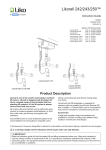
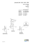
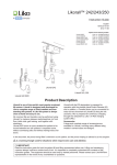
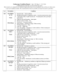
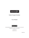
6.1
Likorall™
Likorall 200, 240, 242, 243, 250
Periodic inspection
2014-06-26
Customer Reference:
Lift type:
..............................................................
Contract No: ..................................................................
Prod No:
Version:
..............................................................
Name:
..................................................................
Serial No:
..............................................................
Address:
..................................................................
(Zip Code)
..................................................................
Prod. Year: ..............................................................
The patient lift must be thoroughly inspected at least once per year. Inspection and service must be carried out by
Hill-Rom/Liko authorized personnel.
If the system is installed in a corrosive environment such as indoor pool or bathroom, please see section 15 before starting
inspection. Make a color print of this instruction.
INSPECTION POINTS
1
2
3
4
5
6
7
8a
8b
9
10
11
Approved
Generalinspection
Carriages
Emergency Stop Hand control
Electrical emergency lowering device
SSP Limit Switch
Lift Strap
Mechanical emergency lowering (242)
Fixed strap-stop (242)
TDM & R2R Hook (200 & 242 R2R)
Slingbar Charger function
Not
approved
To be actioned:


.............................................................................
.............................................................................
.............................................................................
.............................................................................
.............................................................................
.............................................................................
.............................................................................
.............................................................................
.............................................................................
.............................................................................
.............................................................................
.............................................................................
LOAD TESTING
12 Mechanical lowering load test (242)
13 Maximumloadrailsystem


.............................................................................
.............................................................................
DOCUMENTATION
14 Instructions/Instructionguide


.............................................................................
ENVIRONMENTAL IMPACT
15 Corrosiveenvironments


.............................................................................
Approval to use the patient lift
 Approved
 Not approved
 To be actioned
If the patient lift has one or more inspection point with result “Not approved” the system must not be used. If the system
has one or more inspection point with result “To be actioned” these actions should be performed immediatley.
After performed actions sign below. If anything is unclear or if you have questions, please contact Hill-Rom/Liko or your
local Hill-Rom/Liko representative. Contact information is to be found at www.liko.com.
Inspection performed by: ____________________________________
Date: ____________________
Final approval by:
_____________________________________
Approval date: ____________
Next inspection:
_____________________________________
Inspection performed in accordance with ISO 10535:2006 Annex B- Periodic inspection
106
www.liko.com
www.liko.com
Periodic
Inspection Likorall © Copyright Liko AB
6.1
Instructions for Likorall™
the inspection points
Inspection points
Likorall 200
Likorall 242
2
1
3
2
5
6
7
1
3
8b
8a
6
5
10
7
4
9
9
10
4
R2R
Likorall 243 & 250
2
1
3
5
6
7
10
4
Periodic Inspection Likorall
Periodic Inspection Likorall 107
www.liko.com
www.liko.com
6.1
Likorall™
Instructions for the inspection points
1
-
General inspection
Verify presence of decal with model type and serial number.
Check the front plastic cover for cracks.
Check rear plastic cover for cracks and that the end-cover screws are in place.
Check aluminium body for dents or scratches.
2 Carriages
- Verify that carriages are secured to motor with bolts and nyloc nuts.
- Roll the carriage within the rail. Verify that each wheel turns freely and the plastic wheel bearing covers not are
cracked or missing.
R2R Turnable Hanger:
- Verify that the centre pin is held secure with a split pin.
Carriage with brake:
- If applicable, check that the carriage brake assembly tightens and holds.
- Check the brake function of the carriage.
3 Emergency Stop
- Press in the emergency stop button. Verify that it holds and locks in the closed position. If the emergency stop
cord is attached, check that it is secured properly.
- With the Emergency Stop button pressed in, check that the motor does not operate when the hand control
buttons are pressed.
- Turn the red emergency button in the direction of the arrows. Verify that the button releases from the locked
position into the raised, open position.
4
-
Hand control
Check cord for exposed wear or tear in the insulation sleeve.
Inspect casing for damage, verify dust & water seal is intact.
With the emergency-stop out, press each button and check for corresponding lift operation.
5 Electrical emergency lowering device
- Test the electrical emergency lowering device by pulling down the handle (Likorall 200) or pressing the up and
down arrows on the electronic card cover. Check for corresponding lift operation.
6
-
SSP Limit Switch
Check that the (2) mounting screws secure the micro switch e-card to the motor casing.
Check function of twist protection.
With the emergency stop out, move the lifts trap all the way up against the SSP Limit switch. Check that
the motor does not operate when touching the SSP Limit switch.
7 Lift Strap
- Using the hand control, lower the strap to its maximum extension. Inspect the belt for frayed edges, heavy
wrinkles or wear-through areas.
- Verify that the Q-link is secure on strap. Slide plastic cover off the Q-link and visually inspect that the lifts trap
safety pin is seated securely in the middle recess of the Q-link.
8a Mechanical emergency lowering (Likorall 242)
- Make sure the hole at the emergency lowering not exceeds 12 mm / 0,47 inch.
-
EMERGENCY
LOWERING
Attach the sling bar to the lift strap. Make sure the sling bar is correctly mounted.
Verify the position of the red plastic adjustable stop at the top of the Spring magazine.
Ensurethatthesnap-fitisinterlockedandsecure.
Apply slight manual downward pressure on the sling bar. Simultaneously pump
the red handle on the mechanical emergency-lowering. Verify that the spring
action handle lowers and recoils upward and that the strap is let out of the Spring magazine.
Manually elevate the sling bar so there is no weight on the mechanical lowering assembly. Simultaneously pump
the red handle until the strap rewinds up to the red plastic adjustable stop.
Ensure that the red plastic handle cover is in place.
8b Fixed strap-stop (Likorall 242)
- Verify that screws (2) are tight in two-piece assembly
- If requested and/or necessary, reset the strap-stop height according to service manual instructions.
Periodic Inspection Likorall Periodic Inspection Likorall
108
www.liko.com
www.liko.com
6.1
Likorall™
Instructions for the inspection points
9
-
TDM & R2R Hook (Likorall 242 R2R and Likorall 200)
Manually press and lower the plastic covers and spring assembly away from the aluminium hook. Release the
springassemblyandverifythatthespringsnapsbackagainstthehook,providingasecuresnap-fitlock.
Verify that the screw joints are tight.
10 Sling bar
- Visually inspect the sling bar to detect any scratches, sharp edges
or deformities.
- Check that the unit rotates freely on its bearings.
- Make sure both safety latch clips are mounted and fall back against the body of the sling bar.
- Verify that the sling bar fasteners are tight.
- On old model of sling bar, made of steel; Verify that the o-ring is present and positioned in the center bolt groove.
11 Charger function
- With the emergency stop out, insert the hand control into the wall-mounted charger outlet (110 - 240V). Visually
inspect that diode lights on the charger unit and hand control light up according to the User Manual or the Quick
reference guide.
Load testing
12
Mechanical lowering load test (50 kg / 110 lbs) (Likorall 242)
With the emergency stop out, and the strap with the sling bar lowered, secure the weights.
Using the hand control, raise the weights approximately 10-15 cm (4-6 inch).
Firmly apply increasing downward pressure on the red emergency-lowering handle until the strap begins to
slowlylowertheweighttothefloor.Removetheweightsandrewindthestraptoitsoriginalposition,as
described in inspection point 8a.
13 Maximum-load test
Likorall 200: 200 kg / 440 lbs
Likorall 240: 180 kg / 400 lbs
Likorall 242: 200 kg / 440 lbs
Likorall 243: 230 kg / 507 lbs
Likorall 250: 250 kg / 550 lbs
Stop
-
With the emergency stop out, and the strap with the sling bar lowered,
secure the weights.
Using the hand control, raise the maximum load 50 cm
Make sure the lift strap does not drift more than 15 cm (6 inch)/ 30 sec.
Lower the maximum load to the start position.
Listen for peculiar noises and vibrations.
Max.load
Note:
Never go below start position with the maximum load!
Make sure the batteries are fully charged before maximum load test!
If the low-battery alarm sounds during the lift, the battery must be recharged prior to load testing.
If the low-battery alarm sounds during the lift with fully recharged batteries, the batteries must be replaced.
50cm
Start
Documentation
14 Instructions / Instruction guide.
- Make sure Instruction guide or Quick reference guide, to the lift unit, are available.
Periodic Inspection Likorall Periodic Inspection Likorall
109
www.liko.com
www.liko.com
6.1
Likorall™
Instructions for the inspection points
15 Environmental Impact – corrosive environments
Due to the environment an overhead system is installed in, components may be subject to corrosion.
High temperature, high relative humidity, poor ventilation, presence of chlorine and different combinations of
these factors, will affect the corrosion rate.
Depending on material type a corrosion attack can occur suddenly or in other cases form gradually.
The corrosion rate and type of corrosion attack might be different in one area of the installation compared to
another. Fixing points classified as safety critical, installed in a corrosive environment such as indoor
pool or bathroom, must be inspected. When a component has reached a certain stage of corrosion it
might need to be replaced.
Note! Print out in color.
Check for visible severe corrosion and material loss and identify if components need to be replaced.
Galvanized steel
These pictures describes the evaluation method for all galvanized steel components.
1. New bolt
2. Acceptable
3. Replace
4. NOT acceptable
1. A galvanized steel component.
2. White rust on a component appears when the surface treatment corrodes.
3. Red rust appears when the actual steel has started to corrode. Corroding steel will result in material loss
and should therefore be replaced.
4.Acomponentcoveredinredrustisunfitforuse.
Powder coated steel
These pictures describes the evaluation method for all powder coated steel components.
1. New
2. Acceptable
3. Replace
4. NOT acceptable
1. A powder coated steel component.
2. Local discoloration may occur in close proximity to corroding non-painted components. Stains on the
painted surface is acceptable.
3. Cracks in the paint and red corrosion under the paint is a sign of corroding steel. Corroding steel will result
in material loss and should therefore be replaced.
4.Acomponentwithpeelingcoating,bubblesinthepaintandredcorrosionunderthepaintisunfittouse.
Periodic
Inspection
Likorall Periodic Inspection
Likorall
110
www.liko.com
www.liko.com
Likorall™
Instructions for the inspection points
Safety critical fixing points:
•
Carrier bolts and pins
•
Load bearing components below lift motor.
Periodic Inspection Likorall 6.1
Example of load bearing parts:
111
www.liko.com
Likorall™
3EN200405 Rev. 9
112
www.liko.com
6.2
Likorall™
Rail system
Periodic Inspection
3EN111001 Rev 10
System information
Customer references
Type of Rail system: ..................................................
Agreement No: .............................................................
S/N:
Name:
.............................................................
Approved Max Load: ..................................................
Address:
.............................................................
Year of Installation:
Post code:
.............................................................
..................................................
..................................................
The Rail System must be thoroughly inspected at least once per year. Inspection and service must be carried out by
Hill-Rom/Liko authorized personnel.
See Installation condition checklist on next page to determine how to perform inspection points 1 and 3.
Make a color print of this instruction.
INSPECTION POINTS
Approved
INSTALLATION
1 Generalinspection
2 Labels/Signs
3 Ceiling/Pendant/CeilingFixture
4 Wall/WallBracket
Not
approved
To be actioned:


.............................................................................
.............................................................................
.............................................................................
.............................................................................
LOAD-BEARING PARTS / RAIL SYSTEM
5 UprightSupport

6 Primaryrail

7 SecondaryRail

8 TraverseCarriage

9 Endstop

10 RailJoint


.............................................................................
.............................................................................
.............................................................................
.............................................................................
.............................................................................
.............................................................................
POWER UNIT
11 Liftmotor


.............................................................................
LOAD TESTING
12 Maximumloadrailsystem
13 Extendedmaximumloadtest


.............................................................................
.............................................................................
DOCUMENTATION
14 Instructions / Instruction guide


.............................................................................
ENVIRONMENTAL IMPACT
15 Corrosiveenvironments


.............................................................................
Approval to use the overhead system
Approved
Not approved
To be actioned
Not approved: If the system has one or more inspection points with result “Not approved” the system must not be used.
To be actioned: Actions according to the “Instructions for the inspection points” should be performed immediatley. After
performed actions sign below. If anything is unclear or if you have questions, please contact Hill-Rom/Liko or your local
Hill-Rom/Liko representative. Contact information is to be found at www.liko.com.
Inspection performed by: ____________________________________
Date: ____________________
Final approval by:
_____________________________________
Approval date: ____________
Next inspection:
_____________________________________
Inspection performed in accordance with ISO 10535:2006 Annex B- Periodic inspection
113
www.liko.com
www.liko.com
Periodic
Inspection Rail System © Copyright Liko AB, 2014 June
6.2
Likorall™
Installation condition
checklist
Instructions
for inspection
points
This checklist helps to determine ways to perform inspection points 1 and 3, depending on what
environment the system is installed in.
All other inspection points has to be performed according to the instructions.
Environment:
Non corrosive environment
Corrosive environment
e.g. bathroom or other high humidity
environment.
Accessible fixing points: Partly accessible fixing
points:
Non accessible fixing
points:
All attachments are visible
E.g. false ceiling with
inspection hatches
E.g. false ceiling
•
•
•
•
Inspectaminimumof
20%(atleasttwo)of
thefixingpoints.
•
Inspectallfixingpoints. •
Performcorrosion
inspectionaccordingto
section15.
•
•
Chlorinated corrosive environment •
e.g. indoor pool
Periodic Inspection Rail System, 3EN111001 Rev. 10
Periodic
Inspection Rail System •
Inspectallfixingpoints. •
Performcorrosion
•
inspectionaccordingto
section15.
114
Inspectaminimumof •
20%(atleasttwo)of
thefixingpoints.
Iflessthan20%can
beinspected,extended
maximumloadtest
mustbeperformed
onnonvisiblefixing
points,accordingto
section13
Extendedmaximum
loadtestaccordingto
section13.
Inspectaminimumof •
20%(atleasttwo)of
thefixingpoints.
Iflessthan20%can
beinspected,extended
maximumloadtest
mustbeperformed
onnonvisiblefixing
points,accordingto
section13
Performcorrosion
inspectionaccordingto
section15.
Extendedmaximum
loadtestaccordingto
section13.
Inspectallfixingpoints. •
Performcorrosion
inspectionaccordingto •
section15.
NOTE!
Make inspection with
inspection hatches or
similar.
Inspectallfixing
points.
Performcorrosion
inspectionaccordingto
section15.
NOTE!
Make inspection with
inspection hatches
or similar.
www.liko.com
www.liko.com
Likorall™
Instructions for inspection points
6.2
3
4
8
5
2
6
11
10
9
7
1 General inspection
•
•
•
•
•
Verify that there is a valid Installation Certificate for the
overhead lift system.
Inspect that the distance between the installation points
and the overhang match the instructions for the rail and
the max load for installed lift unit.
Se Tables in Overhead System Installation Hand Book.
Inspect that the overhead lift system has no visible
damage or deformation.
Inspect a minimum of 20% of the fixing points to
make sure that bolts and nuts are not loose, or see
“Installation condition checklist” on previous page if
fixing points are unaccessible.
Use the appropriate inspection method for the bolts.
(This is given by the supplier of the bolt.)
2 Decal / Labels
•
•
Inspect the S/N on the label, if available
Make sure the maximum load at the decal on the rail, is
equal to, or larger than the maximum load for the lift unit
installed in the system.
Serie No / Serial No
xxxxxx
Märklast / Max load
kg
TESTED
www.liko.com
3 Ceiling / Pendant / Ceiling Fixture
•
•
Inspect a minimum of 20% (at least two) of the fixing
points to make sure that bolts and nuts are not loose, or
see “Installation condition checklist” on previous page if
fixing points are unaccessible.
(See 1 General inspection)
Periodic Inspection
Rail System,
3EN111001
Rev.10
Periodic
Inspection
Rail
System
115
www.liko.com
www.liko.com
6.2
Likorall™
Instructions for inspection points
4 Wall / Wall Bracket
•
•
Inspect that there is no play between the wall and the
bracket.
Inspectthefixingbetweentherailandthewallbracket.
5 Upright Support
•
•
•
Make sure that there is no play between the fixingpoints
in the wall and the upright support.
Inspectthefixingbetweenthewallandtheupright
support.
Inspectthefloorfordamage/deflectionaroundthe
bottom of the upright support.
6 Primary rail, ( straight rail, traverse )
•
•
•
Makesurethereareatleasttwofixingsperrail.
Inspect that joint gap is max 2 mm / 0,08 inch. (A)
Makesurethattherailjointissupportedbyafixingora
proper joint section.
(A)
7 Secondary Rail
•
Inspect that the drawing affect in the system is
acceptable, by placing a force (F) on one side.
The secondary rail (B) should then run freely.
(B)
F
8 Traverse Carriage
•
Inspect that the carriers are functioning correctly without exercise. Listen for abnormal sounds from movable
parts.
Periodic
Inspection
Rail
System
Periodic
Inspection
Rail System,
3EN111001
Rev.10
116
www.liko.com
www.liko.com
Likorall™
Instructions for inspection points
Instructions for inspection points
6.2
9 End stop
Inspect
9• End
stop that safetythrough bolts with locking nuts are
mounted.
• Inspect that safetythrough bolts with locking nuts are
• mounted.
Inspect that the end stop is correctly mounted.
•
Inspect that the end stop is correctly mounted.
10 Rail Joint (in rail, pendant and ceiling bracket)
• Rail
Inspect
to make
that bracket)
bolts and nuts
10
Jointthe
(inRail
rail,Joint
pendant
andsure
ceiling
are
tightened
and
there
is
no
play
between
parts.
• Inspect the Rail Joint to make sure that boltsthe
and
nuts
• are
Make
sure theand
Railthere
Jointisisno
assembled
with the parts.
joints in
tightened
play between
the middle.
• Make
sure the Rail Joint is assembled with the joints in
the middle.
11 Lift motor
• Lift
See
Periodic inspection for the particular lift /product in the rail system.
11
motor
(Available
at www.partner.liko.net)
• See Periodic
inspection for the particular lift /product in the rail system.
(Available at www.partner.liko.net)
12 Maximum load rail system
• Maximum
Carry out load
load test
lift motor carriages and rail
12
rail with
system
system,
using
maximum
for carriages
the rail system,
across
• Carry out load test with liftload
motor
and rail
the whole
lifting
area, by load
manoeuvre
the system,
load along
system,
using
maximum
for the rail
across
each
primary
rail,
andby
then
in a Z pattern.
the
whole
lifting
area,
manoeuvre
the load along
• each
Listenprimary
for unusual
noises
rail, and
thenand
in avibrations.
Z pattern.Check for any
abnormalitiessuchasdeflection,abnormalmovement
• Listen
for unusual noises and vibrations. Check for any
or
resistance.
abnormalitiessuchasdeflection,abnormalmovement
or resistance.
Periodic Inspection Rail System Periodic Inspection Rail System, 3EN111001 Rev. 10
117
www.liko.com
www.liko.com
6.2
Likorall™
Instructions for inspection points
13A Extended maximum load test
STRAIGHT RAIL SYSTEM
•
•
Apply the maximum load for the overhead rail system. Travel the applied load along the rail from one end
stoptotheotherendstop,withapauseundereachfixingpoint.Travelasthedashedlineshows.
Listenforunusualnoisesandvibrations.Checkforanyabnormalitiessuchasdeflection,movementor
resistance.
Pendant
End Stop
Carriage
Pendant
Primary rail
Max.load
Max.load
1
2
Pause
Attachment 1 etc.
End stop
End stop
Carriage
Rail
Max.load
Periodic Inspection Rail System Periodic Inspection Rail System, 3EN111001 Rev. 10
118
www.liko.com
www.liko.com
6.2
Likorall™
Instructions for inspection points
13B Extended maximum load test
TRAVERSE SYSTEM
•
•
•
•
•
Apply the maximum load for the overhead rail system.
Place the carriage with the applied load at the end stop of the secondary rail (1). Move the secondary rail,
withapauseundereachfixingpoint,fromoneendstoptotheotherendstopofthefirstprimaryrail.
Continue by moving the applied load diagonally through the centre of the system over to the other side, as
the dashed line shows.
Nowcontinuebymovingthesecondaryrailwiththeappliedload,from(2),withapauseundereachfixing
point, from one end stop to the other end stop of the second primary rail.
Listenforunusualnoisesandvibrations.Checkforanyabnormalitiessuchasdeflection,movementor
resistance.
Primary rail
End Stop
Carriage
Primary rail
Secondary rail
Max.load
Max.load
1
2
Secondary rail
Max.load
Max.load
Pause
Attachment 1 etc.
End stop
End stop
Secondary rail
Max.load
End stop
End stop
1
Periodic Inspection Rail System Periodic Inspection Rail System, 3EN111001 Rev. 10
Max.load
2
119
www.liko.com
www.liko.com
6.2
Likorall™
Instructions for inspection points
14 Instructions / Instruction guide
•
Make sure Instruction guide or Quick reference guide, to the lift unit, are available.
15 Environmental Impact – corrosive environments
Due to the environment an overhead system is installed in, components may be subject to corrosion.
High temperature, high relative humidity, poor ventilation, presence of chlorine and different combinations of
these factors, will affect the corrosion rate.
Depending on material type a corrosion attack can occur suddenly or in other cases form gradually.
The corrosion rate and type of corrosion attack might be different in one area of the installation compared to
another. Fixing points classified as safety critical, installed in a corrosive environment such as indoor
pool or bathroom, must be inspected. When a component has reached a certain stage of corrosion it
might need to be replaced.
Note! Print out in color.
Check for visible severe corrosion and material loss and identify if components need to be replaced.
Galvanized steel
These pictures describes the evaluation method for all galvanized steel components.
1. New bolt
2. Acceptable
3. Replace
4. NOT acceptable
1. A galvanized steel component.
2. White rust on a component appears when the surface treatment corrodes.
3. Red rust appears when the actual steel has started to corrode. Corroding steel will result in material loss
and should therefore be replaced.
4.Acomponentcoveredinredrustisunfitforuse.
Powder coated steel
These pictures describes the evaluation method for all powder coated steel components.
1. New
2. Acceptable
3. Replace
4. NOT acceptable
1. A powder coated steel component.
2. Local discoloration may occur in close proximity to corroding non-painted components. Stains on the
painted surface is acceptable.
3. Cracks in the paint and red corrosion under the paint is a sign of corroding steel. Corroding steel will result
in material loss and should therefore be replaced.
4.Acomponentwithpeelingcoating,bubblesinthepaintandredcorrosionunderthepaintisunfittouse.
Periodic
Inspection
Rail
System
Periodic
Inspection
Rail System,
3EN111001
Rev. 10
120
www.liko.com
www.liko.com
6.2
Likorall™
Instructions for inspection points
Safetycriticalfixingpoints:
•
Ceiling and wall attachments
•
Load bearing bolts and nuts in
Example of load bearing bolts and nuts:
- Pendants
- Ceiling and wall brackets
- Traverse carriers
- Switches and turntables
•
End stop
Periodic Inspection Rail System Periodic Inspection Rail System, 3EN111001 Rev. 10
121
www.liko.com
www.liko.com
Likorall™
3EN200405 Rev. 9
122
www.liko.com
7.1
Likorall™
Likorall 200/240/242/243/250
Preventative Maintenance
2013-11-05
Customer Reference:
Contract No:
Lift type:
Product No:
Name:
Version:
Serial No:
Address:
Prod. Year:
(Zip Code)
To ensure maximum life cycle should Preventative Maintenance be carried out according to the table below.
Inspection and service must be carried by HillRom/Liko authorized personnel. Instructions for the check
points, from the next page.
Check points:
Carriage
Month 12 24 36 48 60 72 84 96 108 120
1 Carriage cleaning ...........................................................................
2 Bearing inspection..........................................................................
Bearing replacement ......................................................................
Motor
3 Lift strap replacement.....................................................................
4 Battery inspection...........................................................................
Battery replacement .......................................................................
5 Sling bar ........................................................................................
Interval/Month:
Date:
Serviced by:
3EN200405 Rev. 9
123
www.liko.com
7.1
Likorall™
Check points
1
2
4A&B
3
5
Instructions regarding the check points for
Likorall 200/240/242/243/250
1. Carriage cleaning
Tools required
13 mm
A. Remove the carriage from the rail and
clean the wheels and the inside surface
of rails with a moist cloth.
Adjustable
brake
B. Place carriage in rail, mount motor. Tighten carriage screws. Adjust the brake on the carriage
(friction brake).
3EN200405 Rev. 9
124
www.liko.com
7.1
Likorall™
Likorall 200/240/242/243/250
2. Bearing inspection and replacement
Tools required
Spare part No:
31290060 Plastic wheel with bearing.
Not for IRC-carriage 3126114 and IRC Traverse Adapter 3102540
Bearing replacement recommended every 5th year
3. Lift strap replacement
Spare part No. according to spare part list.
Lift strap replacement recommended every 5th year
4 Battery inspection and replacement
Tools required
3 mm
200
Battery tester Prod. No. 2101100
- Remove the cover by unfasten the 4 screws and than pull out the batteries.
- Check the battery with Battery tester Prod. No. 2101100, signal should be audible for more than 5 sec.
If not, replace battery with Spare part No. 31290007.
- Replace battery according to assembly instruction for Spare part 31290007.
Battery replacement recommended every 3rd year
3EN200405 Rev. 9
125
www.liko.com
7.1
Likorall™
Likorall 200/240/242/243/250
5. Sling bar cleaning
Tools required
Only on SlingBar Standard:
17 mm
6 mm
A. Unfasten sling bar from Likorall.
B. Clean sling bar and center bolt on old type of slingbar.
Cleaning of sling bar and center bolt recommended every year
3EN200405 Rev. 9
126
www.liko.com
8.0
Likorall™
Likorall 200 / 240 / 242 / 243 / 250
Product changes
Likorall 243 ES, NA
Likorall 250 ES, NA
Likorall 200
Likorall 242 S
Likorall 242 ES
Likorall 242 S R2R
Likorall 242 ES R2R
Likorall 243 ES
Likorall 250 ES
Likorall 250 S IRC
Likorall 200
Prod. No. 3121001
Likorall 242 ES
Likorall 242 ES R2R Likorall 242 S
Likorall 242 S R2R Prod. No. 3122005-3122006 / NA
Prod. No. 3122007-3122008 / NA
Prod. No. 3122009-3122010 / NA
Prod. No. 3122011-3122012 / NA
Likorall 243 ES, natural
Likorall 243 ES, white
Prod. No. 3123001 / NA
Prod. No. 3123002 / NA
Likorall 250 ES, natural
Likorall 250 ES, white
Likorall 250 S, IRC
Prod. No. 3122501 / NA
Prod. No. 3122502 / NA
Prod. No. 3124050
Likorall 240 natural / white
Likorall 242 natural / white
Prod. No. 3120001-3121617 - Discontinued 2004
Prod. No. 3122001-3122004 - Discontinued 2004
2013
Changes
Type
Prod. No.
Rev. From S/N
Proj.
Spareparts to old versions of Likorall has been
discontinued.
Likorall 240
31290052
31290053
31290005
-
-
1910
- The liftstraps has been modified. New type of
seam and new 145 mm long treaded bolt.
All Lift Strap Spare Parts has got new spare
part numbers. (see Spare Parts List)
Likorall 200
3121001
02
8 411 000
1797
Likorall 242 S
3122009
3122010
3122011
3122012
3122009NA
3122010NA
3122011NA
3122012NA
02
02
02
02
02
02
02
02
8 024 000
8 024 000
8 024 000
8 024 000
286 200
286 200
286 200
286 200
Likorall 242 ES
3122005
3122006
3122007
3122008
3122005NA
3122006NA
3122007NA
3122008NA
02
02
02
02
02
02
02
02
8 103 700
8 103 700
8 103 700
8 103 700
429 200
429 200
429 200
429 200
Likorall 243 ES
3123001
3123002
3123001NA
3123002NA
02
02
02
02
8 205 400
8 205 400
368 200
368 200
Likorall 250 ES
3122501
3122502
3122501NA
3122502NA
02
02
02
02
8 306 300
8 306 300
6 604 200
6 604 200
Likorall 250 S IRC
3124050
02
5 500
3EN200405 Rev. 9
127
www.liko.com
8.0
Likorall™ 200 / 240 / 242 / 243 / 250
Product changes
2012
Changes
Type
Prod. No.
Rev. From S/N:
Proj.
- New longer and grey lift straps.
- The motor has been modified.
- New version of PCBA
- Revision numbers (Rev.) are implemented.
It is visible on the product label at the lift and
on the packaging label.
- Clearifying instructions regarding maximum
load testing has been inserted in our
documentation.
(never go below start position with max load)
Likorall 200
3121001
01
8 406 676
Likorall 242 S
3122009
3122010
3122011
3122012
3122009NA
3122010NA
3122011NA
3122012NA
01
01
01
01
01
01
01
01
8 000 001
8 000 001
8 000 001
8 000 001
260 001
260 001
260 001
260 001
1748
1817
Likorall 242 ES
3122005
3122006
3122007
3122008
3122005NA
3122006NA
3122007NA
3122008NA
01
01
01
01
01
01
01
01
8 100 001
8 100 001
8 100 001
8 100 001
420 001
420 001
420 001
420 001
Likorall 243 ES
3123001
3123002
3123001NA
3123002NA
01
01
01
01
8 200 001
8 200 001
362 301
362 301
Likorall 250 ES
3122501
3122502
3122501NA
3122502NA
01
01
01
01
8 300 001
8 300 001
6 600 001
6 600 001
Likorall 250 S IRC
3124050
01
2001
Changes
Type
Prod. No.
S/N:
Due to production problems some Likorall was
produced according to proj 754, with shorter
black lift strap, old version of motor, and PCBA.
Likorall 200
3121001
7 900 001 - 8 405 800 8 405 969 - 8 406 299
Likorall 242 S
3122011
7 920 001 - 8 016 112
8 016 169 - 8 016 399
2011
Temporary solution until project 1748 was
released.
Likorall • 3EN200405 Rev. 9
128
Proj.
www.liko.com
8.0
Likorall™ 200 / 240 / 242 / 243 / 250
Product changes
2011
Changes
Type
From S/N
Project
New layout on decal and product labels.
Likorall 200
1690/1694
New layout on decal and product labels.
Likorall 242 S
1690/1694
Likorall 242 ES
Likorall 243 ES
Likorall 250 ES
Likorall 250 S IRC
Spare part 31290078 Emergency guard activator,
reintroduces.
Changes
Likorall 242 S (NA)
Likorall 242 ES (NA)
Likorall 243 ES (NA)
Likorall 250 ES (NA)
285 300
427 700
366 306
6 603 100
Type
From S/N
Project
- The Hand Control Cable is 15 cm longer and more flexible. Likorall 200
- The lifting range has been modified to 205 cm.
- New longer lift strap.
- The motor has been modified.
8 405 801
1211/1051
- The lifting range has been modified to 205 cm.
- New longer and grey lift straps.
- The motor has been modified.
- New fuse (12A) and fuse holder
Likorall 242 S
8 016 001
1211/1051
Likorall 242 ES
Likorall 243 ES
Likorall 250 ES
Likorall 250 S IRC
8 102 001
8 203 501
8 303 501
3000
Proj 1211/1051 was never inplemented on Likorall NA.
Likorall 242 S (NA)
Likorall 242 ES (NA)
Likorall 243 ES (NA)
Likorall 250 ES (NA)
-
Changes
Type
From S/N
Project
New type of ceiling lift, prepared for continuous charging
through the rail system by In-Rail charging system (IRC)
Likorall 250 S IRC
2001-2500
(pre serial)
1099
New cover with integrated emergency stop collar and
emergency stop cord. Lift strap equipped with Q-link is
now standard on Likorall 243 ES and Likorall 250 ES.
Likorall 242 S
Likorall 242 ES
Likorall 243 ES
Likorall 250 ES
8 007 961
8 100 714
8 201 237
8 301 629
754
New cover with integrated emergency stop collar and
emergency stop cord.
Likorall 200
Likorall 242 S (NA)
Likorall 242 ES (NA)
Likorall 243 ES (NA)
Likorall 250 ES (NA)
8 401 443
284 580
426 991
365 346
6 601 769
2010
Likorall • 3EN200405 Rev. 9
129
www.liko.com
8.0
Likorall™ 200 / 240 / 242 / 243 / 250
Product changes
2009
Changes
Type
From S/N
Project
New version of electronic card; version F
Likorall 200
8 401 051
1030
Changes
Type
From S/N
Project
New version of Electronic card.
Likorall 242 S
Likorall 242 ES
Likorall 243 ES
Likorall 250 ES
8 000 001
8 100 001
8 200 001
8 300 001
560
New version of Electronic card.
Likorall 242 S (NA)
Likorall 242 ES (NA)
Likorall 243 ES (NA)
Likorall 250 ES (NA)
278 548
425 687
363 741
6 600 301
Changes
Type
From S/N
Project
Current limit changed from 10.5A to 11.5A.
Likorall 242 ES
424689
383
Safety Squeeze Protection upgraded with Twist Protection. Likorall 242 S
Likorall 243 ES
Likorall 242 ES
267210
362586
424379
156
Hang-Up for Hand control
266387
424229
362487
183
2007
2005
Likorall 242 S
Likorall 242 ES
Likorall 243 ES
Likorall • 3EN200405 Rev. 9
130
www.liko.com
Likorall™
3EN200405 Rev. 9
131
2.0
www.liko.com
© Copyright Liko AB, 2014 June
w w w . l i k o . com
Manufacturer:
Liko AB
SE-975 92 Luleå
Sweden