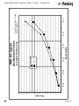
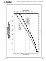
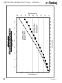
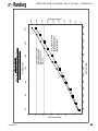
1
SERVICE MANUAL
LN-9260-07.1
(Replaces LN-9260-07)
March - 2010
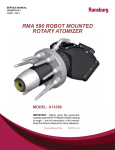
RMA TM-303
TOMIZER
ROBOT MOUNTED ROT
AR
Y A
ROTAR
ARY
AT
DIRECT CHARGE
MODEL: A12303
IMPOR
TANT
IMPORT
ANT:: Before using this equipment,
carefully read SAFETY PRECAUTIONS,
starting on page 1, and all instructions in
this manual. Keep this Service Manual for
future reference.
Service Manual Price: €40.00
40.00 (Euro)
$50.00 (U.S.)
NOTE: This service manual has been superceded from service manual number LN-9260-07 to
service manual number LN-9260-07.1
LN-9260-07.1. Reasons for this change are noted under "Manual Change
Summary" inside the back cover of this manual.
LN-9260-07.1
RMA-303 Rotary Atomizer Direct Charge - Contents
CONTENTS
SAFETY:
PAGE
1-4
SAFETY PRECAUTIONS........................................................................................................... 1
HAZARDS / SAFEGUARDS...................................................................................................... 2-4
INTRODUCTION:
5-28
FEATURES..................................................................................................................................5
GENERAL DESCRIPTION......................................................................................................... 6
SPECIFICATIONS...................................................................................................................... 7
IMPORTANT NUMBERS............................................................................................................ 8
GRAPHICAL INFORMATION.....................................................................................................9-21
RMA-303 DIRECT TOOL POINT, CENTER OF GRAVITY AND
ENVELOPE DIMENSIONS.........................................................................................................22-25
CIRCUIT SCHEMATIC (METRIC)..............................................................................................26
CIRCUIT SCHEMATIC (FRACTIONAL).................................................................................... 27
VALVE SCHEMATIC...................................................................................................................28
INSTALLATION:
29-38
AIR FILTER INSTALLATION...................................................................................................... 29
TUBE SIZE/AIR PRESSURE REQUIREMENTS...................................................................... 29
EQUIPMENT GROUNDING AND SAFETY RECOMMENDATIONS...................................... 30-31
AIR HEATER REQUIREMENTS................................................................................................ 31-32
AIR FILTRATION REQUIREMENTS......................................................................................... 33
MOUNTING................................................................................................................................. 34
ELECTRICAL AND FIBER OPTIC CONNECTIONS................................................................ 34
FLUID CONNECTIONS.............................................................................................................. 34
TYPICAL INSTALLATION........................................................................................................... 34
FLUID TUBING CONNECTION REQUIREMENTS.................................................................. 34
TYPICAL INSTALLATION RMA-303.......................................................................................... 35
TUBING BUNDLE INSTALLATION............................................................................................ 36
BUNDLE LUBRICATION............................................................................................................ 36
RMA-303 WIRING INSTALLATION............................................................................................ 37
INTERLOCKS.............................................................................................................................. 38
OPERATION:
39-48
FLUID FLOW RATE CONTROL.................................................................................................39
FLUID VALVE CONTROL.......................................................................................................... 40
TURBINE SPEED....................................................................................................................... 40
BEARING AIR ADJUSTMENT................................................................................................... 41
SHAPING AIR KIT #1, #2, #3, #4................................................................................................41-43
BRAKE AIR..................................................................................................................................44
ELECTROSTATIC VOLTAGE.................................................................................................... 44
TARGET DISTANCE.................................................................................................................. 44
GENERAL OPERATING SEQUENCE...................................................................................... 44-46
LOW VOLTAGE CABLE INSTALLATION AND REMOVAL..................................................... 47
LOW VOLTAGE CABLE ON ROBOT........................................................................................ 48
(Continued On Next Page)
LN-9260-07.1
RMA-303 Rotary Atomizer Direct Charge - Contents
CONTENTS (Cont.)
PAGE
MAINTENANCE:
49-76
O-RINGS..................................................................................................................................... 49
CLEANING PROCEDURES....................................................................................................... 49-50
VIBRATION NOISE..................................................................................................................... 51
TURBINE MAINTENANCE......................................................................................................... 51
GENERAL MAINTENANCE....................................................................................................... 51
PREVENTIVE MAINTENANCE.................................................................................................. 51-53
BELL CUP PREVENTIVE MAINTENANCE............................................................................... 53-54
BELL CUP CLEANING............................................................................................................... 55
CLEANING SHAPING AIR HOLES........................................................................................... 56
RMA-303 PREVENTIVE MAINTENANCE SCHEDULE........................................................... 57-58
DISASSEMBLY PROCEDURE.................................................................................................. 58-70
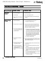
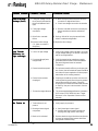
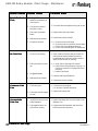
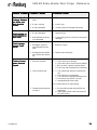
TROUBLESHOOTING GUIDE................................................................................................... 71-74
TYPICAL BELL CUP PARTS BREAKDOWN............................................................................ 75
PARTS IDENTIFICATION:
77-100
RMA-303 ROTARY ATOMIZER DIRECT CHARGE
MODEL IDENTIFICATION.......................................................................................................... 77-79
RMA-303 ASSEMBLY / PARTS LIST......................................................................................... 80-82
A11206-00 REAR PLATE ASSEMBLY / PARTS LIST.............................................................. 83
A11241-00 VALVE MANIFOLD ASSEMBLY / PARTS LIST..................................................... 84
SHAPING AIR KITS.................................................................................................................... 85-86
A11351-01/02 CUP WASH LINE ASSEMBLIES........................................................................ 86
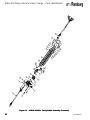
A12000-XXXXXX TUBING BUNDLE ASSEMBLY (FRACTIONAL)......................................... 87
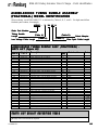
A12000-XXXXXX TUBING BUNDLE ASSEMBLY (FRACTIONAL)
MODEL IDENTIFICATION / PARTS LIST................................................................................. 88-90
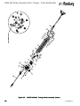
A12215-XXXXXX TUBING BUNDLE ASSEMBLY (METRIC)................................................... 91
A12215-XXXXXX TUBING BUNDLE ASSEMBLY (METRIC)
MODEL IDENTIFICATION.......................................................................................................... 92-94
RMA-303 RECOMMENDED SPARE PARTS........................................................................... 94-97
ASSEMBLY TOOLS.................................................................................................................... 98
ACCESSORIES.......................................................................................................................... 99
SERVICE KITS............................................................................................................................ 100
LUBRICANTS AND SEALERS................................................................................................... 100
AIR FILTER / ELEMENT REPLACEMENT................................................................................ 100
WARRANTY POLICIES:
101
LIMITED WARRANTY................................................................................................................. 101
LN-9260-07.1
RMA-303 Rotary Atomizer Direct Charge - Contents
LN-9260-07.1
RMA-303 Rotary Atomizer Direct Charge - Safety
SAFETY
SAFETY PRECAUTIONS
Before operating, maintaining or servicing any
ITW Ransburg electrostatic coating system, read
and understand all of the technical and safety
literature for your ITW Ransburg products. This
manual contains information that is important for
you to know and understand. This information
relates to USER SAFETY and PREVENTING
EQUIPMENT PROBLEMS. To help you recognize
this information, we use the following symbols.
Please pay particular attention to these sections.
A WARNING! states information to alert you
to a situation that might cause serious injury
if instructions are not followed.
A CAUTION! states information that tells
how to prevent damage to equipment or how
to avoid a situation that might cause minor
injury.
A NOTE is information relevant to the
procedure in progress.
! WARNING
> The user MUST read and be familiar with
the Safety Section in this manual and the ITW
Ransburg safety literature therein identified.
> This manual MUST be read and thoroughly
understood by ALL personnel who operate,
clean or maintain this equipment! Special
care should be taken to ensure that the
WARNINGS and safety requirements for
operating and servicing the equipment are
followed. The user should be aware of and
adhere to ALL local building and fire codes
and ordinances as well as NFPA-33
SAFETY STANDARD, prior to installing,
operating, and/or servicing this equipment.
! WARNING
> The hazards shown on the following page
may occur during the normal use of this
equipment. Please read the hazard chart
beginning on page 2.
While this manual lists standard specifications
and service procedures, some minor deviations
may be found between this literature and your
equipment. Differences in local codes and plant
requirements, material delivery requirements, etc.,
make such variations inevitable. Compare this
manual with your system installation drawings
and appropriate ITW Ransburg equipment manuals
to reconcile such differences.
Careful study and continued use of this manual will
provide a better understanding of the equipment
and process, resulting in more efficient operation,
longer trouble-free service and faster, easier
troubleshooting. If you do not have the manuals
and safety literature for your Ransburg system,
contact your local ITW Ransburg representative
or ITW Ransburg.
1
LN-9260-07.1
RMA-303 Rotary Atomizer Direct Charge - Safety
AREA
HAZARD
SAFEGUARDS
Tells where hazards
Tells what the hazard is.
Tells how to avoid the hazard.
may occur.
Spray Area
Fire Hazard
Improper or inadequate operation and maintenance procedures will cause a fire
hazard.
Fire extinguishing equipment must be present in the
spray area and tested periodically.
Spray areas must be kept clean to prevent the
accumulation of combustible residues.
Smoking must never be allowed in the spray area.
Protection against inadvertent
arcing that is capable of
causing fire or explosion is
lost if any safety interlocks
are disabled during operation.
Frequent power supply shutdown indicates a problem in
the system requiring correction.
The high voltage supplied to the atomizer must be
turned off prior to cleaning, flushing or maintenance.
When using solvents for cleaning:
Those used for equipment flushing should have flash
points equal to or higher than those of the
coating material.
Those used for general cleaning must have flash
points above 100oF (37.8oC).
Spray booth ventilation must be kept at the rates
required by NFPA-33, OSHA, and local codes. In
addition, ventilation must be maintained during cleaning
operations using flammable or combustible solvents.
Electrostatic arcing must be prevented.
Test only in areas free of combustible material.
Testing may require high voltage to be on, but only as
instructed.
Non-factory replacement parts or unauthorized
equipment modifications may cause fire or injury.
If used, the key switch bypass is intended for use only
during set-up operations. Production should never be
done with safety interlocks disabled.
Never use equipment intended for use in waterborne
installations to spray solvent based materials.
The paint process and equipment should be set up and
operated in accordance with NFPA-33, NEC, and
OSHA requirements.
LN-9260-07.1
2
RMA-303 Rotary Atomizer Direct Charge - Safety
AREA
HAZARD
SAFEGUARDS
Tells where hazards
Tells what the hazard is.
Tells how to avoid the hazard.
may occur.
General Use and
Maintenance
Improper operation or maintenance may create a hazard.
Personnel must be given training in accordance with
the requirements of NFPA-33.
Personnel must be properly
trained in the use of this
equipment.
Instructions and safety precautions must be read
and understood prior to using this equipment.
Comply with appropriate local, state, and national
codes governing ventilation, fire protection, operation
maintenance, and housekeeping. Reference OSHA,
NFPA-33, and your insurance company requirements.
Electrical
Equipment
High voltage equipment is
utilized. Arcing in areas of
flammable or combustible materials may occur. Personnel are
exposed to high voltage during
operation and maintenance.
The power supply, optional remote control cabinet,
and all other electrical equipment must be located
outside Class I or II, Division 1 and 2 hazardous
areas. Refer to NFPA-33.
Turn the power supply OFF before working on the
equipment.
Protection against inadvertent
arcing that may cause a fire or Test only in areas free of flammable or combustible
explosion is lost if safety circuits material.
are disabled during operation.
Testing may require high voltage to be on, but only
Frequent power supply shut-down as instructed.
indicates a problem in the system
Production should never be done with the safety
which requires correction.
circuits disabled.
An electrical arc can ignite coating
materials and cause a fire or Before turning the high voltage on, make sure no
objects are within the sparking distance.
explosion.
Explosion Hazard/ Halogenated hydrocarbon solvents for example: methylene
Incompatible
chloride and 1,1,1,-TrichloroMaterials
ethane are not chemically compatible with the aluminum that
might be used in many system
components. The chemical reaction caused by these solvents
reacting with aluminum can become violent and lead to an
equipment explosion.
3
Aluminum is widely used in other spray application
equipment - such as material pumps, regulators,
triggering valves, etc. Halogenated hydrocarbon
solvents must never be used with aluminum
equipment during spraying, flushing, or cleaning.
Read the label or data sheet for the material you
intend to spray. If in doubt as to whether or not a
coating or cleaning material is compatible, contact
your material supplier. Any other type of solvent
may be used with aluminum equipment.
LN-9260-07.1
RMA-303 Rotary Atomizer Direct Charge - Safety
AREA
HAZARD
SAFEGUARDS
Tells where hazards
Tells what the hazard is.
Tells how to avoid the hazard.
may occur.
Toxic Substances Certain material may be harmful
if inhaled, or if there is contact
with the skin.
Follow the requirements of the Material Safety Data
Sheet supplied by coating material manufacturer.
Adequate exhaust must be provided to keep the air
free of accumulations of toxic materials.
Use a mask or respirator whenever there is a chance
of inhaling sprayed materials. The mask must be
compatible with the material being sprayed and its
concentration. Equipment must be as prescribed by
an industrial hygienist or safety expert, and be
NIOSH approved.
Spray Area/
High Voltage
Equipment
There is a high voltage device
that can induce an electrical
charge on objects which is capable of igniting coating materials.
Parts being sprayed must be supported on conveyors or hangers and be grounded. The resistance
between the part and ground must not exceed 1
megohm.
Inadequate grounding will cause
a spark hazard. A spark can
ignite many coating materials and
cause a fire or explosion.
All electrically conductive objects in the spray area,
with the exception of those objects required by the
process to be at high voltage, must be grounded.
Any person working in the spray area must be
grounded.
Unless specifically approved for use in hazardous
locations, the power supply and other electrical control
equipment must not be used in Class 1, Division 1 or
2 locations.
Personnel Safety/ The bell atomizer can rotate at
speeds up to 70,000 rpm. At
Mechanical
these speeds, the edge of the
Hazards
Robot Work
Area - General
Use and
Maintenance
Personnel must stay clear of the bell whenever it is
rotating.
applicator can easily cut into
skin. Loose articles of clothing
can also be caught by the rotating bell.
Before touching the bell, the turbine air must be shut
off.
Improper use or maintenance can
lead to hazardous conditions,
particularly from unexpected
robot manipulator movement.
Applicator adjustments or maintenance should be
done after the robot is taken out of service. Do not
adjust or repair the applicator if the robot is operating
or standing ready to start.
If the bell has been rotating, allow at least two minutes for it to come to a complete stop before touching it.
Refer to robot operating instructions for the procedures
to take the robot out of service.
LN-9260-07.1
4
RMA-303 Rotary Atomizer Direct Charge - Introduction
INTRODUCTION
FEA
TURES
FEATURES
Features which make the RMATM-303 Robot
Mounted Rotary Atomizer - Direct Charge
advantageous for use in electrostatic applications
include:
! Assembly components made of durable
engineered resin material for optimum
mechanical strength and solvent resistance.
! Heavy duty design ensures excellent service
life even when subjected to the quick motions
of robotic applications.
! Proven long life turbine motor capable of
speeds up to 70 krpm. (See "Specifications"
in the "Introduction" section of this manual for
bell cup speed ratings.)
! Serrated and non-serrated bell cups are
available for application flexability and color
match. All bell cups are made using
Titanium material. the 55mm bell cup is also
available in aluminum.
! Independent shaping air passages provide
a wide range of pattern size options at low
air consumption.
! Two independent shaping air supply tubes
for pattern control.
! Aerodynamic design for ease of cleaning external surfaces.
! 60o angled body provides more maneuverability and facilitates robotic programming.
! Small light weight package allows better
maneuverability in tight areas.
! Negligible maintenance down time. With
the quick disconnect feature, an atomizer
can be exchanged in less than 2 minutes
for off-line maintenance.
! The easily removable front and rear
shrouds, turbine assembly and the internally
mounted fluid valves, make off-line
maintenance more efficient and economical.
! Fast color changes are achieved using center
feed fluid delivery and the fluid valves provide
for simultaneous paint push out while solvent
washes the feed tube and bell cup.
! Internal and external bell wash is quick and
efficient. Solvent is controlled at the feed tube
with an internally mounted solvent valve.
Externally mounted regulators control the flow.
! Less waste to the spray booth, with the dump
valve located internally next to the feed tube.
! No external high voltage cable. The
internally mounted high voltage cascade
requires only low voltage control wiring.
! Compact high voltage control system. The
MicroPak cascade control takes only 1/4 of
the space in a 19-inch Euro rack, leaving
room for additional control modules.
! Various adapter plates available to match
most robotic mounting configurations.
! Direct charging of fluid (solventborne paint)
promotes high transfer efficiency.
! Large range of fluid tip sizes available.
! Speed control uses reliable magnetic pickup
for fiber optic transmission of rotational speed
data.
5
LN-9260-07.1
RMA-303 Rotary Atomizer Direct Charge- Introduction
GENERAL DESCRIPTION
Bell Cup Assembly
All bell cups are made of high strength Titanium.
They are available in 65mm serrated, non-serrated
for base coat applications. 55 and 65mm serrated
for clear coat applications. A 30mm and 55mm
aluminum bell cup is available.
Break-Away Feature (Optional)
The RMA-303 can be converted to have a breakaway feature, by replacing the five (5) stainless steel
screws with five (5) special designed plastic screws
(77524-00). This feature is meant to reduce the
damage to the atomizer, robot, etc. If a collision
occurs, the five (5) plastic break-away screws fail
and the atomizer will break free. This will leave the
break-away ring and the mounting ring attached to
the robot.
Air Bearing T
urbine Assembly
Turbine
The air bearing turbine assembly with bell cup is
mounted to the air manifold assembly with a turbine
retaining ring.
Air Manifold Assembly
The atomizer extension is angled at 60° for robot
applications. The fluid feed tube and fiber optic
turbine speed emitter are threaded into the front of
the manifold. The turbine, fluid, and air manifold are
separated from the bell plate assembly by five support rods. Nested between the manifolds and the bell
plate is the high voltage cascade.
Bell Plate Assembly
The bell plate assembly is designed to be at ground
potential when mounted to the robot plate component
within the tubing bundle assembly. The air and fluid
ports are compactly oriented for use in robotic
applications. The interior air supplies are ported
through the five support rods and also directly tubed
to the air manifold assembly. On the exterior side of
the bell plate, the ports are provided with o-ring seals
so that the atomizer can be quickly mated and
secured to the robot plate.
Robot Plate
The robot plate is a component of the tubing bundle
assembly and intended to be permanently mounted
to the robot. A wrist adapter is also available, which
matches the robot's mounting configuration. The
incoming air lines, fluid lines, low voltage cable, and
fiber optic cable are connected to the fittings provided
on the back of the robot plate. The bell plate of the
atomizer assembly is secured to the robot plate with
a threaded retaining ring.
Power Supply and Controls
The high voltage cascade located inside the
RMA-303 is controlled by the MicroPakTM control
unit. The low voltage output of the MicroPak is
multiplied by the internal cascade to the high
voltage level required. This eliminates the need for
a high voltage cable. A low voltage cable
interconnects the cascade and MicroPak control.
The MicroPak Eurocard format is designed to fit in
a conventional 19-inch or 10-inch rack and requires
a 24 V power input at a maximum 3 amps. The
MicroPak and the internal cascade will produce
voltages up to 100,000 VDC.
The MicroPak is designed to electronically limit
current to provide safe operation in a spray booth.
The voltage and current draw of the atomizer are
continuously displayed on the MicroPak control
panel. Voltage and overcurrent limits are adjustable
on the front of the MicroPak. MicroPak internal
safety circuits will shut down the system on overcurrent and cable faults.
With additional control modules, all of the functions of
RMA-303 and MicroPak can be controlled by a
programmable controller. A Serial Atomizer module
pneumatically controls the speed of the rotary
atomizer with dynamic feedback through a fiber
optic transmitter located on the applicator. An
AirTronic module pneumatically controls the
atomizer’s inner (pattern control) and outer (cut-in
control) shaping air. A Serial Digital module
pneumatically controls the paint, solvent, and dump
valves located on the atomizer. An I/O module
provides communication between these modules
and the PLC.
The above modules are mounted in one 19-inch rack
and interconnected through a common mother board.
LN-9260-07.1
6
RMA-303 Rotary Atomizer Direct Charge - Introduction
SPECIFICA
TIONS *
SPECIFICATIONS
Bearing Air Supply:
(Nominal):
Electrical
Power Supply
Type:
MicroPak
Charging Method:
Direct
Output Voltage:
30-100 kV Variable
Output Current:
125 µA Maximum
Brake Air Supply:
(Nominal):
Eurocard Atomizer
Module
Maximum Fluid Pressure Supply:
Paint:
200 psi (1379 kPa)
Solvent:
150 psi (1035 kPa)
Eurocard AirTronic
Module
Fluid Flow Rate:
Turbine Speed
Control:
Inner/Outer
Shaping Air
Control:
Part Sprayability: Determine sprayability of
part to be coated using Test Equipment (76652)
(Paint Conductivity Meter)
Mechanical
Length:
(See Figures 1-4)
Diameter:
(See Figures 1-4)
Approximate Weight:
Atomizer Only:
17.3 lbs.
(7.83 Kg) max.
Total Payload with
Robot Plate & Adapter: 20.1 lbs.
(9.12 Kg) max.
Turbine Type:
Air Bearing Impulse
Drive
Turbine Air Supply:
Variable
(See "Pressure Flow Data Charts" in this section.)
7
90 psig (±10 psi)
(621 kPa ±69 kPa)
2.9 SCFM (82 slpm)
Maximum/Minimum
Turbine Speed:
65mm Bell Cup
55mm Bell Cup
Continuous
70K rpm max.
20K rpm min.
Maximum Angular
Velocity for Turbine
(Robot Motion):
250°/sec.
Shaping Air #1 (SAI):
Variable
(See "Pressure Flow Data Charts" in this section.)
Shaping Air #2 (SAO): Variable
(See "Pressure Flow Data Charts" in this
section.)
60-100 psig
(414-689 kPa)
25-700 cc/min.
Bell Cup Cleaning Time
(Internal/External):
2-7 sec. (Approx.)
Color Change Time: Dependent on system
configuration, fluid pressures, fluid viscosity, fluid
line lengths, etc.
Speed Readout: Magnetic pick-up, unidirectional fiber optic transmission
Atomizer Replacement
Time:
Less than 2 min.
Bell Cup Replacement
Time:
Less than 2 min.
Minimum Control Equipment
Requirements: (Versions listed or higher)
MicroPak
LECU5004-11 (V3.83)
Atomizer Module 76011-00 (V3.42)
I/O Module
A11435-00
(V1.4) (4-20 mA) (0-10V)
* Specifications and ratings based on
testing at sea level standard conditions.
LN-9260-07.1
RMA-303 Rotary Atomizer Direct Charge - Introduction
IMPOR
TANT NUMBERS
IMPORT
Record these numbers in a log book for future reference.
The last digits of the Atomizer serial number are also the Turbine serial numbers.
LN-9260-07.1
8
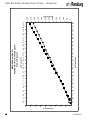
9
0
10
20
30
40
50
0
10
20
40
50
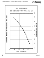
TURBINE SPEED - (k)RPM
30
60
70
TURBINE SPEED VS PRESSURE- NO LOAD
80
330
310
290
270
250
230
210
190
170
150
130
110
90
70
50
30
10
RMA-303 Rotary Atomizer Direct Charge - Introduction
LN-9260-07.1
AIR PRESSURE - kPA
AIR PRESS. - PSIG
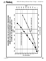
RMA-303 Rotary Atomizer Direct Charge - Introduction
Graphical information provided for reference only for all
all charts.
charts. Unless otherwise specified, all pressure
data shown was measured 12-inches (304.85mm) behind the applicator.
0
50
100
150
200
250
300
350
400
0
5
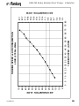
TURBINE SPEED VS AIR CONSUMPTION- NO LOAD
10 15 20 25 30 35 40 45 50 55 60 65 70 75 80
TURBINE SPEED - (k)RPM
0
2
4
6
8
10
12
14
AIR CONSUMPTION - SCFM
AIR CONSUMPTION - SLPM
LN-9260-07.1
10
11
0
10
20
30
40
50
60
70
80
90
100
0
5
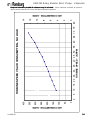
TURBINE SPEED - (k)RPM
10 15 20 25 30 35 40 45 50 55 60 65 70 75 80
TURBINE SPEED vs PRESSURE
LOAD @ 700cc-Water
690
650
610
570
530
490
450
410
370
330
290
250
210
170
130
90
50
10
RMA-303 Rotary Atomizer Direct Charge - Introduction
LN-9260-07.1
AIR PRESSURE - kPA
AIR PRESSURE - PSIG
LN-9260-07.1
50
100
150
200
250
300
350
400
450
500
550
600
650
700
0
5
10 15 20 25 30 35 40 45 50 55 60 65 70 75 80
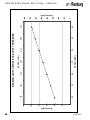
TURBINE SPEED - (k)RPM
TURBINE SPEED vs AIR CONSUMPTION
LOAD @ 700cc-Water
24.1
22.7
21.2
19.8
18.3
16.9
15.4
14.0
12.5
11.1
9.6
8.2
6.7
5.3
3.8
2.4
RMA-303 Rotary Atomizer Direct Charge - Introduction
12
AIR CONSUMPTION - SCFM
AIR CONSUMPTION - SLPM
13
0
20
40
60
80
100
120
45
1.59
52
1.84
60
2.12
Air Flow (slpm)
67
2.37
Air Flow (scfm)
74
2.61
82
2.90
BEARING AIR FLOW RATE VS SUPPLY PRESSURE
88
3.12
0
100
200
300
400
500
600
700
800
RMA-303 Rotary Atomizer Direct Charge - Introduction
LN-9260-07.1
Pressure (kPa)
Pressure (psi)
LN-9260-07.1
0.0
0.3
0.5
0.8
1.0
1.3
1.5
1.8
2.0
2.3
2.5
2.8
3.0
3.3
3.5
3.8
4.0
4.3
0
10
20
30
Speed (0 to krpm)
40
50
60
70
19 ft, 12mm & 6 ft, 10mm Tube
80
RMA-303 Average Acceleration Pressure measured 12 inches behind
applicator- 100 psi (690 kPa)
Unloaded 65mm Bell Cup
RMA-303 Rotary Atomizer Direct Charge - Introduction
14
Time (sec)
15
70-60
70-50
0
1
2
3
4
5
6
7
8
70-30
Speed (krpm)
70-40
100 psi 6x4
10
9
60 psi 6x4
11
12
13
14
15
16
(unloaded 65mm Bell Cup)
RMA-303 Spindle
Deceleration Times
70-20
70-0
Pressure measured 12 inches
behind applicator
RMA-303 Rotary Atomizer Direct Charge - Introduction
LN-9260-07.1
Time (sec)
LN-9260-07.1
0
10
20
30
40
50
60
75
100
3.5
125
150
5.3
175
200
7.1
225
275
12.4
300
325
350
14.1
375
400
425
15 ft (4.6 m) of 8mm x
6mm Tubing. Pressure
Measured 12 inches
Behind applicator
15 ft (4.6 m) of 8mm x 6
mm Tubing. Pressure
Measured 6 ft Behind
Applicator
10.6
Air Flow (slpm)
250
8.8
Air Flow (scfm)
Flow vs. Pressure
Single Shape Air- Single Supply Source
A12089-01/-02 SHAPING AIR KIT
450
15.9
475
0
50
100
150
200
250
300
350
400
RMA-303 Rotary Atomizer Direct Charge - Introduction
16
Air Pressure (kPa)
Air Pressure (psi)
17
0
10
20
30
40
50
60
75
100
3.5
125
150
5.3
175
200
7.1
225
275
12.4
300
325
350
14.1
375
400
425
15 ft (4.6 m) of 8mm x
6mm Tubing. Pressure
Measured 12 inches
Behind applicator
15 ft (4.6 m) of 8mm x 6
mm Tubing. Pressure
Measured 6 ft Behind
Applicator
10.6
Air Flow (slpm)
250
8.8
Air Flow (scfm)
Flow vs. Pressure
Mono Flex Shape Air- Single Supply Source
A12089-06/-07/-08 SHAPING AIR KIT
450
15.9
475
0
50
100
150
200
250
300
350
400
RMA-303 Rotary Atomizer Direct Charge - Introduction
LN-9260-07.1
Air Pressure (kPa)
Air Pressure (psi)
LN-9260-07.1
0
10
20
30
40
50
60
70
150
5.3
200
250
8.8
300
350
12.4
450
19.4
500
550
23.0
600
650
700
(2) 15 ft (4.6 m) of 8mm x
6mm Tubing. Pressure
Measured 12 inches
Behind applicator
(2) 15 ft (4.6 m) of 8mm x
6 mm Tubing. Pressure
Measured 6 ft Behind
Applicator
Air Flow (slpm)
400
15.9
Air Flow (scfm)
Flow vs. Pressure
Mono Flex Shape Air- Dual Supply Source
A12089-06/-07/-08 SHAPING AIR KIT
750
26.5
0
50
100
150
200
250
300
350
400
450
RMA-303 Rotary Atomizer Direct Charge - Introduction
18
Air Pressure (kPa)
Air Pressure (psi)
19
0
10
20
30
40
50
60
70
80
90
75
2.6
4.4
5.3
6.2
7.1
7.9
8.8
9.7 10.6 11.5 12.4 13.2 14.1 15.0 15.9 16.8 17.7 18.5 19.4 20.3 21.2
Air Flow (slpm)
100 125 150 175 200 225 250 275 300 325 350 375 400 425 450 475 500 525 550 575 600
3.5
Air Flow (scfm)
RMA-303 Dual Flex Air
A12089-09/-10/-11 Series Shape Air
Flow vs Pressure
0
50
100
150
200
250
300
350
400
450
500
550
600
RMA-303 Rotary Atomizer Direct Charge - Introduction
LN-9260-07.1
Pressure (kPa)
Pressure (psi)
LN-9260-07.1
0
5
10
15
20
25
30
35
40
45
50
55
60
65
50
1.76
100
3.53
7.06
8.82
150
200
14.12
15.89
300
350
400
450
SHAPING AIR- INNER ANNULUS
AIR FLOW (SLPM)
250
SHAPING AIR- OUTER HOLES
5.29
(SCFM)
10.59
12.36
500
17.65
SHAPING AIR FLOW Vs SUPPLY PRESSURE
30MM GHOST BUSTER SHROUD STYLE
A12089-04/-05 SHAPING AIR KIT
0
50
100
150
200
250
300
350
400
450
RMA-303 Rotary Atomizer Direct Charge - Introduction
20
(kPA)
PRESSURE (PSI)
21
15 / 30
30 / 30
15 / 20
30 / 20
0
200
400
600
Flow Rate
(cc/min)
800
1.2mm (.047), 615
1.1mm (.043), 540
1.0mm (.039), 425
0.9mm (.035), 350
0.7mm (.028), 170
1000
1200
1.6mm (.062), 910
1.6mm (.062), 705
1.2mm (.047), 510
1.1mm (.043), 455
1.0mm (.039), 375
0.9mm (.035), 310
0.7mm (.028), 160
1400
1600
1.6mm (.062), 1380
1.6mm (.062), 1135
1.2mm (.047), 930
1.1mm (.043), 780
1.0mm (.039), 630
0.9mm (.035), 520
0.7mm (.028), 275
1.2mm (.047), 795
1.1mm (.043), 685
1.0mm (.039), 575
0.9mm (.035), 485
0.7mm (.028), 260
Maximum Flow Rate by Tip Size,
Hose Length, and Material Viscocity
RMA-303 Rotary Atomizer Direct Charge - Introduction
LN-9260-07.1
Ft. of 8 x 6mm tubing / Viscocity (seconds in #4 Ford)
LN-9260-07.1
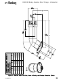
X
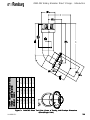
17.46 Inches
(443.6mm)
18.46 Inches
(469.0mm)
19.46 Inches
(494.4mm)
20.46 Inches
(519.8mm)
21.46 Inches
(545.2mm)
TD
4 Inches
(101.6mm)
6 Inches
(152.4mm)
8 Inches
(203.2mm)
10 Inches
(254mm)
12 Inches
(304.8mm)
Figure 1:
8.93 Inches
(226.9mm)
10.66 Inches
(270.9mm)
12.40 Inches
(314.9mm)
14.13 Inches
(358.9mm)
15.86 Inches
(402.9mm)
Y
30MM RMA-303 DIRECT
TOOL POINT
DIMENSIONS
RMA-303 Rotary Atomizer Direct Charge - Introduction
RMA-303 Direct Tool Point, Center of Gravity, and Envelope Dimensions (30mm)
22
23
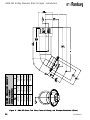
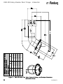
X
17.74 Inches
(450.6mm)
18.74 Inches
(476.0mm)
19.74 Inches
(501.4mm)
20.74 Inches
(526.8mm)
21.74 Inches
(552.2mm)
TD
4 Inches
(101.6mm)
6 Inches
(152.4mm)
8 Inches
(203.2mm)
10 Inches
(254mm)
12 Inches
(304.8mm)
Figure 2:
8.79 Inches
(223.2mm)
10.52 Inches
(267.2mm)
12.25 Inches
(311.1mm)
13.98 Inches
(355.1mm)
15.71 Inches
(399.1mm)
Y
55MM RMA-303 DIRECT
TOOL POINT
DIMENSIONS
RMA-303 Rotary Atomizer Direct Charge - Introduction
RMA-303 Direct Tool Point, Center of Gravity, and Envelope Dimensions (55mm)
LN-9260-07.1
LN-9260-07.1
Y
8.88 Inches
(225.7mm)
10.62 Inches
(269.7mm)
12.35 Inches
(313.6mm)
14.08 Inches
(357.6mm)
15.81 Inches
(401.6mm)
X
17.44 Inches
(442.9mm)
18.44 Inches
(468.3mm)
19.44 Inches
(493.7mm)
20.44 Inches
(519.1mm)
21.44 Inches
(544.5mm)
TD
4 Inches
(101.6mm)
6 Inches
(152.4mm)
8 Inches
(203.2mm)
10 Inches
(254mm)
12 Inches
(304.8mm)
65MM RMA-303 DIRECT TOOL
POINT DIMENSIONS
(MONO FLEX)
RMA-303 Rotary Atomizer Direct Charge - Introduction
Figure 3:
RMA-303 Direct Tool Point, Center of Gravity, and Envelope Dimensions
(65mm/Single Swirl)
24
25
Y
8.88 Inches
(225.7mm)
10.62 Inches
(269.7mm)
12.35 Inches
(313.6mm)
14.08 Inches
(357.6mm)
15.81 Inches
(401.6mm)
X
17.44 Inches
(442.9mm)
18.44 Inches
(468.3mm)
19.44 Inches
(493.7mm)
20.44 Inches
(519.1mm)
21.44 Inches
(544.5mm)
TD
4 Inches
(101.6mm)
6 Inches
(152.4mm)
8 Inches
(203.2mm)
10 Inches
(254mm)
12 Inches
(304.8mm)
POINT DIMENSIONS
(DUAL FLEX)
65MM RMA-303 DIRECT TOOL
RMA-303 Rotary Atomizer Direct Charge - Introduction
Figure 4:
RMA-303 Direct Tool Point, Center of Gravity, and Envelope Dimensions
(65mm/Dual Swirl)
LN-9260-07.1
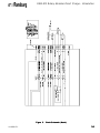
RMA-303 Rotary Atomizer Direct Charge - Introduction
Figure 5:
LN-9260-07.1
Circuit Schematic (Metric)
26
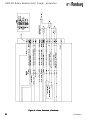
RMA-303 Rotary Atomizer Direct Charge - Introduction
Figure 6: Circuit Schematic (Fractional)
27
LN-9260-07.1
RMA-303 Rotary Atomizer Direct Charge - Introduction
Figure 7: Valve Schematic
LN-9260-07.1
28
RMA-303 Rotary Atomizer Direct Charge - Installation
INST
ALLA
TION
INSTALLA
ALLATION
AIR FIL
TER INST
ALLA
TION
FILTER
INSTALLA
ALLATION
The following air filter installation guidelines are essential for optimum performance:
1. 25mm OD (1-inch OD) minimum inbound main air line.
2. Use only recommended pre-filters and bearing air filters as shown in "Air Filtration
Requirements" chart. Additional system air filtration (i.e., refrigerated air dryer) may also be used if
desired.
3. Mount the bearing air filter as close as possible to the RMA-303. (DO NOT mount further than
30 feet (9.1 meters) away.)
4. DO NOT use Teflon tape, pipe dope, or other thread sealant downstream of the bearing air filter.
Loose flakes of Teflon tape or other sealant can break loose and plug the very fine air holes in the
turbine air bearings.
5. Air heaters are highly recommended for use in the system to minimize the effect of excessively
humid conditions. If the heated air will exceed 120oF (48.9°C), the heater must be located after all
filters to prevent damage to the filter media.
NOTE
NOTE
> Each applicator must have its own filter
for bearing air. Recommended: RPM-418
or equivalent.
> With the exception of fluid, dump, and
bearing air, all other pilot and air supply
lines should be bulkheaded and their diameters increased one size. For example:
turbine air should be increased to a 12mm
OD from bulkhead plate to the volume
booster.
TUBE SIZE / AIR PRESSURE REQUIREMENTS
Metric
Tube Bundle
Bearing Air Supply (BA/PT) 6 X 4mm OD (Yellow)
Bearing Air Return (BA RTN) 4mm OD (5/32") (Yellow)
Turbine Air (T.A)
Pattern Air #2 (SAO/FA)
Pattern Air #1 (SAI/AA)
Brake Air (BRK) (if used)
Paint Valve Control (PT)
Dump Valve Control (DT)
Cup Wash Solvent
Valve Control (ST/RP)
29
10 X 7mm OD (Natural)
8 X 6mm OD (Gray)
8 X 6mm OD (Blue)
6 X 4mm OD (Orange)
4mm OD (5/32") (Green)
4mm OD (5/32") (Silver)
4mm OD (5/32") (Blue)
Fractional Tube
Bundle
Air Pressure
Requirements
1/4" OD X .170" ID (Yellow) 90 psi ± 10 (621 ± 69 kPa)
80 psi ± 20 (at atomizer
4mm (5/32") (Yellow)
card) (552 ± 138 kPa)
3/8" OD X .275" ID (Green) Variable
3/8" OD X .275" ID (Gray) Variable
3/8" OD X .275" ID (Blue) Variable
1/4" OD X .170" ID (Orange) 60-100 psi (414-689 kPa)
4mm OD (5/32") (Green) 80 psi ± 10 552 ± 70 kPa)
4mm OD (5/32") (Silver) 80 psi ± 10 552 ± 70 kPa)
80-100 psi (552-873 kPa)
4mm OD (5/32") (Blue)
LN-9260-07.1
RMA-303 Rotary Atomizer Direct Charge - Installation
EQUIPMENT
GROUNDING AND
SAFETY
RECOMMENDA
TIONS
RECOMMENDATIONS
In electrostatic coating systems, the flow of high
voltage power from the power supply to the atomizer
is insulated from ground and isolated from all other
functions and equipment. When the voltage reaches
the atomizer, it is transferred to the coating material
where, by introducing a negative charge, it causes
the atomized fluid to seek the nearest positive
ground. In a properly constructed and operated
system, that ground will be the target object.
The directed conduction of the electric charge
through its array of wires, cables, and equipment,
is accompanied by a variety of stray electrical
charges passing through the air by various means
such as: air ionization, charged particles in the air
and radiated energy. Such charges may be
attracted to any conductive material in the spray
area. If the conductive material does not provide a
safe drain to electrical ground, which will allow the
charge to dissipate as fast as it accumulates, it
may store the charge. When its electrical storage
limit is reached, or when it is breached by external
circumstances (such as the approach of a
grounded object or person, or one at lower potential),
it may discharge its stored charge to the nearest
ground. If there is no safe path to ground (such as
a ground wire or braided cable) it may discharge
through the air as a spark. A spark may ignite the
flammable atmosphere of a spray area. The hazard
area extends from the point of origin up to as much
as a twenty-foot radius. See the NFPA-33 for
definition and limitations of a hazard area.
It is a simple, but vital matter to be sure that all
conductive objects within the spray area are
grounded. All cabinets, housing, bases, supports
and stands, which are not by design, insulated
from ground, MUST be connected directly and
INDIVIDUALLY to earth ground. Resting on a
concrete floor or being attached to a building
column may not always be sufficient ground.
LN-9260-07.1
In order to provide the best ground connection
possible, always attach a ground wire or insulated
braided cable to the terminal indicated by the
ground symbol and then to a proven ground.
Always check ground connections for integrity.
Some items, such as rotators and paint stands,
may be supported on an insulator, but all
components of the system up to the insulator
MUST be grounded.
NOTE
> ITW Automotive Finishing Group and
ITW Ransburg recommends that ground
connections to earth ground be ¾” insulated copper braided wire. Grounds between
assemblies within a machine should be
ran to a central point within the machine
using #18 insulated stranded copper wire
minimum. All connections should be mechanically sound and have less than five
(5) ohms of resistance between assemblies and the common point. The resistance between the central point and earth
ground should be less than five (5) ohms
as well.
Where items are mounted directly on structural
components such as building columns, the ground
connection MUST still be made. In many cases
the structural component may be painted or coated
with an insulated material and in all cases the
Ransburg equipment will be painted. These
coatings are insulating. The ground connection
must be as perfect as possible. The indicated
ground terminal on the Ransburg equipment will
provide the necessary connection at on end, but
the user must be sure that the other end is secured
to an earth ground. This may be achieved by the
use of a standard ground clamp (properly secured),
by brazing or by piercing the structural component
enough to assure connection. All ground
connections should be made to the most conductive
metallic structural ground available.
30
RMA-303 Rotary Atomizer Direct Charge - Installation
To be sure that everything is properly grounded,
the following steps should be undertaken at least
daily:
1. Inspect all ground wires. Look for good, firm
joints at all points of connection. Look for breaks
in the ground wire. Repair all defects
IMMEDIATELY!
2. Inspect the floor or grates for excessive
accumulation of dried coating material or other
residue. If there is any, remove it!
SAFE GROUNDING IS A MATTER OF
PROPER EQUIPMENT MAINTENANCE
AND INSTALLATION, CORRECT OPERATION AND GOOD HOUSKEEPING
HOUSKEEPING. Daily
inspection of grounding apparatus and conditions,
however, will help prevent hazards that are caused
by normal operations.
BE SURE THAT:
1. All objects in the spray area are grounded.
2. Personnel in the spray area are properly
grounded. (Conductive safety shoes, and
coveralls.)
3. That the target object is properly grounded
(less than 1 megohm resistance).
4. That the high voltage is off except during
normal application.
5. That the high voltage is off and applicators
are grounded during maintenance operations.
6. The spray area is kept free of accumulated
coating deposits.
7. All combustible liquids in the spray area
(outside of automatic delivery systems) are kept
to minimum and are kept in fire safe, grounded
containers. (See NFPA-30 and chapter 6 of
NFPA-33.)
8. Proper ventilation is provided.
AIR HEA
TER
HEATER
REQUIREMENTS
Turbine drive air expands as it moves through the
turbine wheel cavity and as it exits the turbine from
the exhaust port. This expansion will cause
cooling of the exhaust air and the surfaces it
contacts. This same expansion cooling can occur
across the shaping air exit ports. This cooling
effect can cause surface temperatures to fall
below the dew point of the booth, which will result
in condensation on the interior and exterior of the
atomizer, machine, and its components. It is even
possible that the temperature of the supply air may
be below the booth dew point, even without
additional expansion cooling.
Condensation is especially probable in waterborne
applications when booth temperature and relative
humidity levels are typically maintained very high.
This condensation will allow sufficient conductivity
of the surfaces such that they act as an erratic
ground source potential. This can cause damage
to the equipment.
It is therefore, a requirement that turbine exhaust
air temperature be maintained above the booth
dew point to prevent condensation from forming
on atomizer surfaces. Doing so will eliminate
moisture as a potential defect in painted surfaces
as well as extending equipment life. Thus, it is
recommended that air heaters be installed into the
atomizer air supply lines, i.e. turbine drive air,
shaping air, and seal air. The air heaters must be
of sufficient capacity, capable of raising the
incoming air temperature at least 40°F (4.4°C) at
a flow rate of 60 SCFM per applicator.
The actual air heater process setting depends on
applicator fluid flow rate load, booth conditions,
turbine airflow settings, and incoming air
temperature. The heater should be set as low as
possible, sufficient to maintain the applicator
surface temperatures above the dew point in the
booth.
9. Personnel must thoroughly understand the
equipment, its operation and maintenance, and
all safety precautions.
31
LN-9260-07.1
RMA-303 Rotary Atomizer Direct Charge - Installation
Example: With the incoming air temperature at
72°F (22.2°C), an RMA-303 with 65mm bell cup
rotating unloaded at 60 krpm has a turbine outlet
temperature drop of approximately 28°F (-2.2°C)
(@ 40 krpm unloaded, ∆T ~ 14°F (-.10°C)).
Referring to the ASHRAE Psychrometric chart,
the saturation temperature range (dew point) of a
spray booth maintained at 70-75°F / 65-70% RH is
62-68°F (21.1-23.9°C / 65-70° RH is 16.7-20°C).
Thus it is almost certain that the surface
temperatures of the applicator will fall below the
dew point of the booth, and an air heater will be
needed in this case.
NOTE
> Connect air heater to turbine air turbine.
To prevent condensation, an ITW air heater
assembly should be assembled after the air filters.
(Reference the current "Air Heater Assembly"
service manual for further information.)
NOTE
> Failure to use an air heater may cause
damage to equipment or ruin the finished
component being processed.
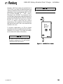
Figure 8:
LN-9260-07.1
A11065-05 Air Heater
32
RMA-303 Rotary Atomizer Direct Charge - Installation
AIR FIL
TRA
TION REQUIREMENTS
FILTRA
TRATION
ITW Filter
No.
Model No
Description/Specifications
Replacement
Element Part No.
HAF-503
Pre-filter, removes coarse amounts of oil, moisture & dirt. HAF-15 Element,
Used upstream of RPM-417 pre-filter (used in systems with One
poor air quality).
RPM-417
Pre-filter, coalescing type, 136 scfm, 98.5% efficiency RPM-32 Elements,
particulate removal .3 to .6 micron, max. aerosol passed 1.0 Carton of 4
micron, max. solid passed .4 micron (dependent upon scfm
requirement per applicator, one RPM-417 can be used with
up to three RMA-303 assemblies).
RPM-418
Bearing air filter, coalescing type, 19 scfm, 99.995% RPM-33 Elements,
efficiency particulate removal .3 to .6 micron, max. aerosol Carton of 8
passed .6 micron, max. solid passed .2 micron (one per
applicator).
CAUTION
NOTE
> Air must be properly filtered to ensure
extended turbine life and to prevent
contamination of the paint finish. Air which is
not adequately filtered will foul the turbine air
bearings and cause premature turbine failure.
The correct type of filters must be used in an
RMA-303 system. The filter elements must
be replaced on a regular schedule to assure
clean air.
> Each applicator must have its own filter
for bearing air. Recommended: RPM-418
or equivalent.
!
> It is the end user’s responsibility to
ensure clean air at all times. Turbine
failure resulting from contaminated air
will not be covered under warranty.
The "Air Filtration Requirements Chart" shows
the pre-filter(s) and bearing air filter which are
recommended for use in RMA-303 systems.
If other filters are incorporated in the system,
the filters to be used must have filtering
capacities equal or better than those shown
in the "Air Filtration Requirements Chart".
> The user must ensure the bearing air
supply is not inadvertently turned off while
the RMA-303 air motor is turning. This will
cause air bearing failure.
33
LN-9260-07.1
RMA-303 Rotary Atomizer Direct Charge - Installation
MOUNTING
FLUID CONNECTIONS
The RMA-303 is equipped with a quick disconnect
assembly. The quick disconnect feature consists
of a robot plate which is permanently attached to
the robot through a wrist adapter plate, and a
mating bell plate which is a part of the RMA-303
atomizer assembly. The atomizer is secured to
the robot plate with a threaded retaining ring.
ELECTRICAL AND FIBER
OPTIC CONNECTIONS
The fiber optic connection is made on the back of
the atomizer's robot plate. The fiber optic cable
comes preassembled with connectors that are
secured in place by set screws tightened from the
side of the robot plate. An adequate ground must
be provided to the mounting plate to ensure that
fluid fittings, etc. are at ground potential.
The paint, solvent, and dump fluid tubing are
connected on the back of the robot plate with
stainless steel compression fittings and PFA Teflon
tubing. Fluid tubing requirements are shown in
"Fluid Tubing Connection Requirements Chart".
TYPICAL INST
ALLA
TION
INSTALLA
ALLATION
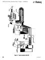
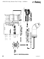
Figure 9 shows a typical installation of the RMA303 and the wiring installation of the applicator with
the MicroPak.
Maximum amount of splices for any length of cable
is 3. The speed detection signal may be affected
if splices are exceeded. Length in any combination
for the fiber optic is 100-feet.
FLUID TUBING CONNECTION REQUIREMENTS
Fixed Atomizer
Paint Line (P)
Cup Wash Solvent Line (SOL)
Dump Line (DL)
LN-9260-07.1
8mm OD X 5mm ID
3/8" OD X 1/4" ID
PFA Teflon
6mm OD X 4mm ID
1/4" OD X .170" ID
PFA Teflon
10mm OD X 7mm ID
Nylon
3/8" OD X 1/4" ID
PFA Teflon
Pressure (Maximum)
200 psi max. (1379 kPa)
150 psi max. (1033 kPa)
200 psi max. (1379 kPa)
34
RMA-303 Rotary Atomizer Direct Charge - Installation
Figure 9:
35
Typical Installation RMA-303
LN-9260-07.1
RMA-303 Rotary Atomizer Direct Charge - Installation
BUNDLE LUBRICA
TION
LUBRICATION
TUBING BUNDLE
INST
ALLA
TION
INSTALLA
ALLATION
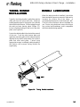
Typically, the tubing bundle is pulled through the
robot arm from the robot wrist side. Keep the
bundle taped except for the portion of the bundle
that will be inside the arm. Pull the tubing through
the wrist and arm, leaving about 250mm (10inches) of tubing sticking out the front of the wrist
plate (see Figure 10).
When the tubing bundle is installed, it should be
lubricated with a generous amount of lubricant to
increase the service life of the tubes. A
recommended lubricant is Shell Alvania EP #02.
There are other lubricants that are available for
use. Prior to using a lubricant, ensure it is silicone
free, resists heat breakdown, and is compatible
with the materials being applied.
Fasten the cable bundle in the robot at the rear exit
of the arm. Push the robot spacer plate and
applicator mounting plate to the robot wrist plate
aligning the top dead center marks of the spacer
plate and robot wrist plate. Fasten using
appropriate screws. Installing the tubing bundle in
this fashion will increase tubing bundle life
significantly.
Figure 10:
LN-9260-07.1
Tubing Bundle Installation
36
37
2
3
+24 VDC
24 VRET
2
24 VRET
3
2
1
J6
1
+24 VDC
J10
1
FACT. GND
J2
MICROPAK
HV GND. BUS
J3
N/C
N/C
N/C
N/C
N/C
N/C
N/C
Figure 11:
3/4" BRAID CABLE
BARE (DRAIN)
BARE (DRAIN)
ORANGE
GRAY
YELLOW
BLUE
GREEN
BLACK
RED
WHITE
EARTH GROUND
RMA-303 Rotary Atomizer Direct Charge - Installation
RMA-303 Wiring Installation
LN-9260-07.1
RMA-303 Rotary Atomizer Direct Charge - Installation
INTERLOCKS
The following system interlocks are required to
prevent equipment damage:
1. Bearing air should remain on at all times and
should be shut off only by turning off the main air
to the pneumatic control cabinet.
!
CAUTION
> When the turbine air is turned off, the
turbine will continue to operate or "coast
down" for about two minutes. Provisions
should be made to assure that the operator
waits at least three minutes, after shutting off
the turbine air and before shutting off the main
air supply.
> The bell cup must be removed when
making flow checks. If the paint is turned on
when the bell is mounted and the turbine shaft
is not rotating, paint will enter the shaft and
possibly damage the air bearing. Material
flow checks (flow rate verification) must be
made with the bell cup off and the turbine not
rotating. Normally pneumatic interlocks will
not allow the paint to trigger on when the
turbine air is off. These interlocks may need
to be bypassed with proper safety procedures
as required.
!
CAUTION
> Bell cup must be rotating at least 30,000
rpm when fluid is triggered. Turning on fluid
without the bell cup spinning may flood the
turbine and cause damage to components.
! WARNING
> Under normal operation, the high voltage
and/or coating material must never be turned
on unless the bell cup is mounted on the
motor shaft and the turbine is rotating.
> Pneumatic input to the turbine air inlet must
be controlled to prevent the turbine from
exceeding the maximum rated speed of
70,000 rpm. (See "Specifications" in the
"Introduction" section.)
> High voltage must never be turned on while
cleaning solvent is being sprayed either
through the applicator supply or the cup
wash line. High voltage and both solvent
triggers must be interlocked.
2. It should not be possible for the coating material to be sprayed unless the turbine is spinning.
3. Two interconnected bearing air ports are provided, one for supply air and the other to be used
as a return signal for measuring bearing air
pressure at the atomizer. If bearing air falls
below 80 psi (551.6 kPa) at the atomizer, the
turbine air should be automatically interlocked
to shut off. This interlock is provided by the
Serial Atomizer Module. (See current "Serial
Atomizer" manual.)
4. High voltage must be interlocked with the
solvent valve pilot signal to prevent solvent flow
while high voltage is energized.
! WARNING
> Never spray solvent with high voltage on.
5. Turbine air and brake air must be interlocked to
prevent both from being used simultaneously.
This interlock is provided by the Serial Atomizer
Module (see current "Serial Atomizer"manual).
6. Any other interlocks required by local code,
national code, or international code.
LN-9260-07.1
38
RMA-303 Rotary Atomizer Direct Charge - Operation
OPERATION
! WARNING
> Operators must be fully trained in safe
operation of electrostatic equipment.
Operators must read all instructions and
safety precautions prior to using this
equipment (see NFPA-33).
As with any spray finishing system, operation of
the RMA-303 involves properly setting the
operating parameters to obtain the best finish
quality for the coating material being sprayed,
while maintaining correct operation and reliability
of the equipment used. Adjustments to operating
parameters, which cover spraying, cleaning, and
on/off control, include:
!
!
!
!
!
!
!
!
!
Coating Materials
Fluid Flow Rate Control
Fluid Valve/Trigger Control
Turbine Speed
Inner Shaping Air (Pattern Control)
Outer Shaping Air (Cut-In Air)
Brake Air
Electrostatic Voltage
Target Distance
FLUID FLOW RA
TE
RATE
CONTROL
Externally mounted fluid regulators or gear pumps
are typically used to control fluid flow. Paint is
supplied to the RMA-303 by way of the tubing
bundle through the robot arm.
The atomizer assembly is equipped with microvalves which are pneumatically operated to direct
the flow of paint to either the feed tube or dump line
and to supply an intermittent solvent to clean the
interior and exterior of the bell cup.
The feed tube has several sized removable tips
available from .7mm to 1.6mm (.027 - .062-inch).
The viscosity and volume of the coating material
being sprayed determine the correct size of feed
tube tip for each installation. (Reference "Fluid Tip
Flow Rate Chart" in the "Introduction" section.)
Fluid Flow Rate Check
In the test mode, the flow rate can be measured by
removing the bell cup from the atomizer, turning
the fluid flow on, and capturing the material in a
graduated beaker or measuring cup for a fixed
period of time (shaping air, high voltage, and
turbine air must be off).
! WARNING
> Electrical discharge of a high electrical
capacitance fluid/paint system can cause
fire or explosion with some materials. If
arcing occurs when a specific coating
material is used, turn the system off and
verify that the fluid is non-flammable. In
these conditions the system is capable of
releasing sufficient electrical and thermal
energy to cause ignition of specific hazardous
materials in air.
39
! WARNING
> Danger of shock and/or personal injury
can occur. Proper grounding procedures
must be followed. Personnel must never
work around the turbine when the turbine is
spinning or when high voltage is turned on.
LN-9260-07.1
RMA-303 Rotary Atomizer Direct Charge - Operation
FLUID V
AL
VE CONTROL
VAL
ALVE
(T
rigger
(Trigger
rigger,, Dump & Solvent)
(See "Figures 5 and 6: Circuit Schematic" in the
"Introduction" section.) The fluid valves in the
RMA-303 are actuated by an air signal. The air
pressure must be greater than 70 psi to assure
proper actuation of the valve. Applying air to the
valve actuator turns on the fluid or air for that valve.
The paint trigger valve controls the paint flow to the
bell. When actuated, paint flows through the valve
to the fluid tube, and into the rear of the bell cup.
The bell cup must be spinning at least 30,000 rpm
when fluid is turned on to enable the fluid to flow
through the bell paint passage and be atomized.
The dump valve controls the paint flow through the
dump line. When actuated, paint flow is directed to
the dump return line. This provides a method of
rapidly removing paint from the incoming line for
cleaning and/or color change. Normally, the dump
valve is not actuated at the same time as the paint
trigger valve since the trigger valve is intended to
cause the fluid to flow to the bell at the prescribed
input pressure.
The solvent valve controls the flow of cup wash
solvent. When actuated, solvent flows through a
separate fluid tube passage and into the rear of the
bell cup . This provides cleaning of the inside of the
bell cup and the exterior of the cup. The solvent
valve should never be triggered at the same time
as the paint trigger valve to prevent solvent from
flowing backward into the paint line.
! WARNING
> Never perform the interior/exterior cup
clean process with high voltage on.
!
CAUTION
> The normal fluid flow range is 25-700 cc/
min. During a color change or when flushing
the system, higher flow rates may be required.
However, the maximum flow rate through the
bell cup must not exceed 700 cc/min., to
avoid solvent or paint from flooding into the
internal portion of the air bearing motor
assembly or front shroud.
> High voltage must be interlocked with the
solvent valve to prevent solvent spraying
while high voltage is on.
TURBINE SPEED
Turbine speed is determined by the input air
pressure/flow at the rear of the atomizer.
Turbine speed is intended to be closed loop
controlled using the fiber optic speed transmitter,
located on the turbine manifold. A speed input to
a remote speed controller, such as the Serial
Atomizer module, is required. (See "Speed and
Pressure" charts in the "Introduction" section.)
NOTE
> The bell rotational speed determines the
quality of atomization and can be varied for
various paint flow rates and paint formulations. For optimum transfer efficiency and
spray pattern control, the bell rotational
speed should be set at the minimum required to achieve proper atomization.
Excessive speed reduces transfer
efficiency!
To color change the applicator, a solvent air chop
must be provided through the main paint line (see
"Figure 7 - Typical Installation RMA-303" in the
"Installation" section).
LN-9260-07.1
40
RMA-303 Rotary Atomizer Direct Charge - Operation
! WARNING
> DO NOT exceed the maximum rated
operating speed and turbine inlet pressure.
Excessive speed may cause air turbine
damage or damage to the bell.
BEARING AIR
ADJUSTMENT
The nominal bearing air pressure is 90 psi
(620.5 kPa), measured at the rear of the atomizer.
Minimum pressure is 80 psi (551.6 kPa) and
maximum pressure is 100 psi (689.5 kPa). The
turbine should never be operated with less than
80 psi (551.6 kPa) bearing air pressure.
Bearing air must be present when turning the
turbine on. Bearing air must remain on when the
turbine air is turned off until the turbine stops
spinning. Never turn off bearing air to cause the
turbine to stop spinning. If connected, brake air
can be used to slow the turbine.
!
CAUTION
> Bearing air MUST be ON and supplied at
a minimum of 80 psig (551.6 kPa) whenever
the turbine is operated. If not, severe bearing
damage will occur. It is recommended that
bearing air be left turned on at all times,
except during maintenance or disassembly.
> Bearing damage (and subsequent turbine
failure) caused by running the turbine without
bearing air WILL NOT be covered under the
ITW Ransburg warranty.
SHAPING AIR KIT #1
A12089-01/02 Shaping Air Kits
for 55mm Bell Cups
(A1
1730-00/01 and A1
1783-00)
(A11730-00/01
A11783-00)
(Pattern Control Air)
Shaping air is used to control the shape and size
of the spray pattern. Lower pressure yields larger
patterns, higher shaping air pressure creates a
smaller pattern. Higher shaping air may assist
with penetrations of atomized particles into cavity
areas. The amount of shaping air should be
optimized for the specific applications. Excessive
air pressure will cause atomized particles to blow
by the target, reducing electrostatic wrap and
lowering transfer efficiency. Excessive air may
also cause some paint particles to bounce off the
target and deposit on the atomizer.
Connection is made using the "blue" 8mm tube
labeled "SAI" on the tubing bundle. The other 8mm
tube is is labeled "SAO" and is "gray" in color and
must be plugged. However, if additional air is
required, this tube can be connected to a secondary
controlled air source. Precautions must be taken
that one does not have a significantly higher
pressure than the other to avoid back flow. This
shaping air combination can be used with either
the aluminum 55mm bell cup or the 55mm Titanium
bell cup. "Air Flow" information can be found in the
"Introduction" section of this manual.
NOTE
> A minimum of 70 slpm (2.6 SCFM)
should always be kept flowing in the inner
shaping air passage to keep the face of the
applicator clean during manual cleaning
breaks.
The RMA-303 is equipped with a bearing air return
line to monitor bearing air pressure at the turbine
manifold. When connected to the remote Serial
Atomizer speed controller, operation of the turbine
will automatically be shut down whenever the
bearing air pressure falls below the dip switch
setting of 80 psi (551.6 kPa).
41
LN-9260-07.1
RMA-303 Rotary Atomizer Direct Charge - Operation
NOTE
> A minimum of 70 slpm (2.6 SCFM)
should always be kept flowing in the inner
shaping air passage to keep the face of the
applicator clean during manual cleaning
breaks.
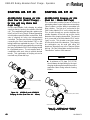
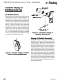
A12089-06 (METAL, DIRECT CHARGE)
A12089-07 (METAL, DIRECT CHARGE WITH RING)
Figure 12: A12089-01 and A12089-02
Shaping Air Kits (55mm)
SHAPING AIR KIT #2
A12089-06/07 Shaping Air Kits
(Mono Flex Air (Direct Charge)
for Use with All 65mm Bell Cups
Only)
A12089-06 (METAL, DIRECT CHARGE)
A12089-07 (METAL, DIRECT CHARGE WITH RING)
Figure 13: A12089-06 and A12089-07
Shaping Air Kits (Mono Flex Air - 65mm)
As the name implies, the shaping air is supplied so
that it is counter to the rotation of the bell cup. This
combination will provide a pattern size from 10inch to 24-inch (250mm - 610mm) depending on
air flow, flud flow, and cup rotation speed.
Connection is made using the "blue" 8mm tube
labeled "SAI" on the tubing bundle. The other 8mm
tube labeled "SAO" is "gray" in color and must be
plugged. However, if additional air is required, this
tube can be connected to a secondary controlled
air source. Precautions must be taken that one
does not have a significantly higher pressure than
the other to avoid any back flow. This shaping air
combination can be used with any 65mm bell cup.
(See "Pressure and Flow Data Charts" in the
"Introduction" section.
LN-9260-07.1
42
RMA-303 Rotary Atomizer Direct Charge - Operation
SHAPING AIR KIT #3
SHAPING AIR KIT #4
A12089-09/10 Shaping Air Kits
(Dual Flex Air (Direct Charge) for Use with Any 65mm Bell
Cups Only)
A12089-04/05 Shaping Air Kits
(Dual Air - 30mm Bell Cups)
As the name implies, both shaping air outlets
supply air that is counter to the rotation of the bell
cup. This combination will provide a pattern size
from 3-inch to 10-inch (76mm - 254mm) depending
on bell rotation speed, fluid flow, and air flow. Both
sets of shaping air holes are independently
controlled. The inner set of holes are supplied by
connecting the "blue" tube labeled "SAI" on the
tubing bundle to a regulated air source. The outer
set of shaping air holes are supplied by connecting
the "gray" tube labeled "SAO" on the tubing bundle
to a regulated source. The air supplies work in
combination with each other to provide desired
results. This combination of shaping air can be
used with any 65mm bell cup.
This combination provides for two air sources to
gain better pattern control, eliminates a secondary
"ghost" pattern, and the ability to penetrate into
deep cavities. The first air is connected to the
"blue" tubes labeled "SAI" on the tubing bundle.
This air exits through an annulus between the
outside diameter of the bell cup and the inside
diameter of the shaping air manifold. The second
air is connected to the tuble labeled "SAI" and is
"gray" in color. This air exits a concentric series
of holes at the front of the atomizer. This shaping
air combination can be used with either the
aluminum 30mm bell cup or the Titanium 30mm
bell cup. "Air Flow" information can be found in the
"Introduction" section of this manual.
NOTE
> A minimum of 70 slpm (2.6 SCFM)
should always be kept flowing in the inner
shaping air passage to keep the face of the
applicator clean during manual cleaning
breaks.
A12089-09 (METAL, DIRECT CHARGE)
A12089-10 (METAL, DIRECT CHARGE WITH RING)
Figure 14:
Shaping Air
A12089-09 and A12089-10
Kits (Dual Flex Air - 65mm)
A12089-04 (METAL, DIRECT CHARGE)
A12089-05 (METAL, DIRECT CHARGE WITH RING)
Figure 15: A12089-04 and
Shaping Air Kits (Dual Air
43
A12089-05
- 30mm)
LN-9260-07.1
RMA-303 Rotary Atomizer Direct Charge - Operation
BRAKE AIR
TARGET DIST
ANCE
DISTANCE
Brake air is used to slow the turbine speed in a
minimum length of time. It is advantageous for
short cycle times during color change, or may be
used to reduce speed or stop the turbine. Never
operate brake air with the turbine air on.
Approximate brake times to reduce the turbine
speed are shown in "Deceleration Time" Chart in
the"Introduction" section. These times are based
on 60 psi (413.7 kPa) and 100 psi (689 kPa) air
pressure at the back of applicator.
The distance between the RMA-303 atomizer and
the target will affect the finish quality and efficiency.
Closer distances give a smaller pattern, wetter
finish, and greater efficiency. Greater distance
will provide a large pattern size and drier finish.
The MicroPak control circuit will enable the
applicator bell to be operated within a few inches
of the target without adjusting the voltage setting.
The recommended target distance is 6 to 12inches (152.4-304.8mm). In general, allow 1-inch
(25.4mm) target distance for every 10kV.
ELECTROST
ATIC
ELECTROSTA
VOL
TAGE
VOLT
GENERAL OPERA
TING
OPERATING
SEQUENCE
The RMA-303 Rotary Atomizer receives a low
voltage control input from the MicroPak to control
the operating electrostatic voltage. (Refer to the
current "MicroPak" maual for detailed operating
instructions.)
NOTE
> If paint defects occur, such as fatty
edges or picture framing, reducing the
voltage should be a last resort. To correct
the problem, adjustments to lead and lag
trigger adjustments should be optimized
first.
> The electrostatic voltage applied to the
RMA-303 will affect pattern size, transfer
efficiency, wrap and penetration into cavity areas. A setting of 30-100kV is appropriate for most applications.
LN-9260-07.1
!
CAUTION
> It is recommended to leave bearing air on,
unless the applicator is being serviced or
removed for service.
Normally, for direct charge painting application,
the process sequence should always be:
•
•
•
•
•
•
Bearing air on (Always on)
Turbine air on
Turbine speed to application speed
Shaping air on
Start fluid flow off part
Voltage on
After spraying the object, the sequence should be:
•
•
•
•
Voltage lowered to 30-50kV
Fluid off
Shaping air to setback volume
Turbine speed to set back speed
(30,000 rpm recommended)
44
RMA-303 Rotary Atomizer Direct Charge - Operation
Recommended sample cup flush sequence is as
follows (voltage must be off) (internal and external
cup wash):
5. Use an alternating trigger sequence of solvent/
air to create a chopping effect. Always insure that
the last step in the sequence is an air push.
1. Turbine speed set to 25,000-30,000 rpm.
6. A typical sequence is .3 seconds solvent, 1.7
seconds air push; repeat 3 times. This sequence
may be modified for other paint and applications.
2. Set shaping air only, no inner air. Set to 350450 slpm (12.4-15.9 SCFM).
3. Point atomizer at a grounded object such as a
booth grate.
4. Maintain solvent pressure of 100-150 psi (6891,034 kPa). Maintain air push pressure at 80-100
psi (552-689 kPa).
5. Use an alternating trigger sequence of solvent/
air to create a chopping effect. Always ensure that
the last step in the sequence is an air push.
A typical sequence is .2 seconds solvent, 1.0
second air push, 1.7 seconds solvent, and 2.0
seconds final air push. This sequence may be
modified for other paints and applications.
6. It is recommended that an in-line fluid filter be
installed to ensure that no foreign debris enters the
fluid tip or the external wash nozzle.
The RMA-303 is versatile in processing the finish
of a component. It can be setup as shown in
Figure 18 to process the typical finish of a target.
Recommended sample cup purge sequence is as
follows (voltage must be off) (internal cup cleaning):
1. Turbine speed set to 25,000-30,000 rpm.
2. Increase shaping air to 350-450 slpm (12.415.9 SCFM).
3. Paint atomizer at booth grate or insert into bell
cleaning station.
4. Maintain solvent pressure of 100-150 psi (6891034 kPa). Maintain air push pressure at 80-100
psi (552-689 kPa).
45
Figure 16:
Typical Paint Sequence
Sequence Event Explanation:
1. Bell to Speed - This is accomplished by a set
point command from either the PLC, robot, or other
input device, through the I/O module.
2. Shaping air - Set to 350-400 SCFM) while
performing a cup flush.
3. Trigger Fluid - An air signal is sent through
the PT line of the tubing bundle. This should occur
when the target is 6-12-inches (152.4-304.8mm)
from the applicator centerline. (Not to be confused
with target distance.)
4. Voltage On - The voltage is turned on from a
signal to the MicroPak. The lag time to full voltage
may be reduced if a setback voltage is used.
Recommended setback voltage is between 30kV
and 50kV.
5. Voltage Off / Setback Voltage - Immediately
preceeds the trigger off. Using a setback voltage
shortens the cascade voltage ramp up-time.
LN-9260-07.1
RMA-303 Rotary Atomizer Direct Charge - Operation
6. Fluid Trigger Off - This should occur when the
target is typically 0-6-inches (0-152.4mm) past
the applicator centerline.
NOTES
7. Shaping Air to Setback - The setback flow
of air should never be below 70 slpm (2.6 SCFM)
for the shape air .
8. Color Change Sequence - Used when color
is changed one to the other. Typical sequence is
shown in Figure 17. (Note: During this
sequence, the applicator should be moved
to a position to collect the waste material.)
The sequence shown is a starting point for
processing, but the final sequence will depend on
the material being sprayed and the solvent used to
purge the applicator with.
Figure 17:
LN-9260-07.1
Typical Color Change Sequence
46
RMA-303 Rotary Atomizer Direct Charge - Operation
LOW VOL
TAGE CABLE
VOLT
INST
ALLA
TION AND
INSTALLA
ALLATION
REMOV
AL
REMOVAL
! WARNING
> Cable connector shell must be electrically
grounded. Electrical noise or other
interference may result!
(See Figures 18 and 19)
A low voltage cable is provided to send power to
the high voltage cascade in the atomizer as well as
sending important information during operation
back to the MicroPak controls. One piece of the
cable is a permanent length of approximately 60inches (1.5 meters) from the robot plate end. The
connecting cable can be ordered in various lengths
depending on the distance required to reach from
the robot arm to the MicroPak controller. The ends
of the cables have a male and female quick
disconnect end. This provides for a quick and
easy removal of the cable at the robot plate if
servicing or replacement is required.
OPTIONAL GROUND CABLE
RAISED MALE KEY
FEMALE KEY SLOT
PUSH TO RELEASE
MALE CONNECTOR AND
APPLICATOR CABLE END
Figure 18:
CONNECT HERE TO BULKHEAD OR
ATTACH GROUND CABLE HERE
BULKHEAD AND MICROPAK
CABLE END
Quick-Disconnect Cables
It is important that the quick disconnect fitting be
secured to a good ground source. The A12241XX cable is supplied with a ground cable which
can be secured to the bulkhead connector and the
other end to a known ground source. The cable
can also be grounded by attaching the bulkhead
connector to a grounded bulkhead plate. The
bulkhead plate can be no more than 1/8-inch
(3.18mm) in thickness. The bracket should be
made as in Figure 19 to hold the connector from
turning. To mate the connectors, align the raised
key section of the cable on the applicator end with
the key groove of the cable that goes to the
MicroPak. Push the male end into the mating
connector until an audible click is heard. Tug on
cable to ensure that it is locked in place. To
remove or disconnect the cable, pull back on the
male connector shell and pull cable back at the
same time. To remove this section from the robot
plate, remove the applicator. Locate the set screw
holding the flanged plastic 9 pin connector. Loosen
with a 3/32" hex key wrench. Pull the cable out
from the robot plate end. Install new cable in
reverse direction, align the 9 pin connector with
the alignment mark on the robot plate face and
tighten set screw. Torque 5-10 lbs•in (0.56-1.13
Nm).
47
LN-9260-07.1
RMA-303 Rotary Atomizer Direct Charge - Operation
Fig 19:
LN-9260-07.1
Low Voltage Cable On Robot
48
RMA-303 Rotary Atomizer Direct Charge - Maintenance
MAINTENANCE
O-RINGS
All o-rings in this atomizer are solvent proof except
the ones on the air bearing spindle. These o-rings
must not be soaked in solvent; if these are exposed
or soaked in solvent, they must be replaced.
These o-rings are engineered to provide a fit
between the air bearing spindle and it's mating
parts to reduce or eliminate harmonic resonance
(vibration).
Some o-rings are Teflon encapsulated. These
o-rings have a limited amount of stretch and will
not return to their original diameters if overstretched. These o-rings are subject to being
distorted more easily than rubber o-rings, so it is
important that they be sufficiently lubricated when
mating parts are installed onto them. They also will
take a square set over time and should be replaced
periodically if mating parts are removed repeatedly
or if a new mating part is installed onto them.
Any o-ring that is cracked, nicked, or distorted
must be replaced.
CLEANING PROCEDURES
! WARNING
Electrical shock and fire hazards
can exist during maintenance. MicroPak supply must be turned off before
entering the spray area and performing
any maintenance procedures on the
atomizer. Spray booth fans should remain on while cleaning with solvents.
>
> Never touch the atomizer bell while
it is spinning. The front edge of the bell
can easily cut into human skin or cut
through gloves and other materials. Be
sure the atomizer bell has stopped spinning before attempting to touch it.
Approximate time for the bell to stop
spinning after turning off turbine drive air
is three minutes.
> Ensure high voltage is off during any
cleaning procedure.
In addition to the above Warning, which relates
to potential safety hazards, the following information must be observed to prevent damage to
the equipment.
!
CAUTION
DO NOT immerse the RMA-303
turbine in solvent or other liquids. Turbine components will be damaged and
warranty will be voided.
>
> Bearing air must be on during all
cleaning procedures to protect the air
bearing components.
49
LN-9260-07.1
RMA-303 Rotary Atomizer Direct Charge - Maintenance
Internal Fluid Path Purge
Cleaning
Cleaning the incoming paint line (from paint supply
source such as color manifold through the fluid
manifold and bell assembly): Turn off the high
voltage solvent supply. With the bell spinning,
open the dump valve and flush the incoming paint
line with solvent or an air/solvent chop. Make sure
the last step of the sequence is air to purge the
dump line of remaining solvent. To speed the
loading of the new paint, leave the dump line open
to allow the air in front of the paint push to escape.
The length of time the dump valve is open depends
on several factors such as viscosity, paint
pressure, etc. Timing should be such that the
dump is closed as the paint reaches the trigger
valve in the atomizer. Paint in the dump line may
cause high voltage issues.
The fluid coil and fluid tube can be cleaned
independently by actuating the solvent valve in the
atomizer. High voltage must be turned off
during this operation and the bell cup must
be spinning (typically 30,000 rpm for cup
flushing sequences).
Bell Cup Cleaning (Cup W
ash)
Wash)
Without Cleaning the Incoming
Paint Line
Turn off the high voltage and trigger valve. With
the bell spinning at 30,00 rpm turn on the external
solvent valve to allow cleaning solvent to flow
through the manifold passages, through the fluid
tube, and onto the bell. The spinning bell will
atomize the solvent, clean out the bell passages
both internally and externally. It is always required
to blow the solvent line dry after the claning
operation. Typical bell speed during the cup flush
sequence is 30,000 rpm. Follow sequence as
outlined for cup wash in "General Operating
Sequence" in the "Operation" section.
!
External Atomizer Surface Cleaning
• Verify that the high voltage is turned off.
• All external surfaces may be cleaned using a
mild solvent and lint free rags to hand wipe
the RMA-303 Turbine drive air must be off,
but leave bearing air on. The inner and outer
shaping air (if applicable) should have approximately 70 slpm air flow through each to
prevent the solvent from entering these passages.
• Do not spray the RMA-303 unit with a solvent
gun used for cleaning. The cleaning fluid under pressure may aid conductive materials to
work into hard to clean areas or may allow
fluids to be forced into the turbine assembly.
• Do not reuse an atomizer bell cup that shows
any sign of damage such as nicks, heavy
scratches, dents, or excessive wear.
• Always final wipe all parts with a non-polar
solvent and wipe dry (high flash Naphtha,
etc.).
! WARNING
NEVER wrap the applicator in plastic to
keep it clean. A surface charge may build up
on the plastic surface and discharge to the
nearest grounded object. Efficiency of the
applicator will also be reduced and damage
or failure of the applicator components may
occur. WRAPPING THE APPLICATOR
IN PLASTIC WILL VOID WARRANTY.
>
CAUTION
> The maximum flow rate of 700 cc/min.
must not be exceeded during a flush routine. Use of an in-line fluid restricter is
recommended. (Example: Hosco P/N
RIL-6-AJ or similar)
LN-9260-07.1
50
RMA-303 Rotary Atomizer Direct Charge - Maintenance
! WARNING
> To reduce the risk of fire or explosion,
OSHA and NFPA-33 require that solvents
used for exterior cleaning, including bell
cleaning and soaking, be nonflammable (flash
points higher than 100oF/37.8oC). Since
electrostatic equipment is involved, these
solvents should also be non-polar. Examples
of non-flammable, non-polar solvents for
cleaning are: Amyl acetate, methyl amyl
acetate, high flash naphtha, and mineral
spirits.
> Do not use conductive solvents such as
MEK to clean the external surfaces of the
RMA-303 without a second cleaning with a
non-polar solvent.
> When using a rag to hand wipe the RMA303, the turbine air should be off, but leave
both the shaping air and bearing air turned on.
Insure that rotation has come to a complete
stop.
VIBRA
TION NOISE
VIBRATION
If the RMA-303 is vibrating or making an unusually
loud noise, it usually means there is an imbalance
situation. The atomizer bell cup may have dried
paint on it or the bell may be physically damaged,
or there may be paint trapped between the bell cup
and shaft preventing the bell cup from properly
seating. If any of these conditions exist, they
MUST be corrected. Excessive imbalance
caused by one of these conditions may result in
bearing damage and turbine failure. Warranty
DOES NOT cover failure caused by imbalanced
loading conditions.
To determine if the bell is dirty or damaged, remove
the bell cup and turn the turbine ON. If the noise
is eliminated, the bell cup is the problem. If the
noise continues, the turbine may be damaged and
should be inspected. Excessive air required to
achieve same speed may indicate a faulty or
contaminated turbine. DO NOT continue to
operate a noisy turbine.
51
! WARNING
> If a bell cup comes off a rotating
shaft because of motor seizing or any
other reason, the Atomizer and bell cup
must be returned to ITW Ransburg for
inspection and evaluation to determine if
the bell can be used in operation.
TURBINE MAINTENANCE
DO NOT attempt to rebuild the turbine. Any
endeavor to disassemble a turbine during
the warranty period will void the warranty.
Contact your authorized distributor or ITW
Ransburg for turbine rebuilding instructions.
GENERAL MAINTENANCE
Verify daily that the operating parameters have not
varied significantly from the normal. A drastic
change in high voltage, operating current, turbine
air, or shaping air, can be an early indicator of
potential component failure.
A laminated poster entitled “Rotary Atomizer
Checklist (AER0075)" is included with the
assembly Literature Kit to be posted near the
station as a handy reference.
Due to the close proximity of high voltage to
ground potential, a schedule must be developed
for equipment maintenance (cleanliness).
PREVENTIVE
MAINTENANCE
Daily Maintenance
(During Each Preventive Maintenance
Break)
1. Verify that high voltage is OFF and that
shaping air, bearing air, and turbine drive air are
ON.
LN-9260-07.1
RMA-303 Rotary Atomizer Direct Charge - Maintenance
2. Open the dump valve, flushing all paint from
the supply lines and valve module.
3. Open the solvent valve, flushing all paint
from the fluid tube and through the atomizer bell
assembly.
4. Re-verify that high voltage is OFF, turbine
drive air is OFF, and that the bell cup has
stopped spinning. The bearing air and shaping
air should remain ON.
5. Clean all external surfaces of the applicator
using a lint-free rag dampened with solvent.
6. After cleaning, all conductive residue must
be removed using a non-conductive solvent.
Since electrostatic equipment is involved, these
solvents should also be non-polar (Naphtha).
7. Inspect bell cup for nicks, dents, heavy
scratches, or excessive wear. Replace if necessary.
8. Check bell cup tightness. Tighten to 50-70
lbs•in (5.65-7.91 Nm) torque.
9. Check the amount of paint build-up on the
outer protective cloth covers, if used. If excessive, replace cover as required. If cloths are
wet, find source and replace with dry cloth covers.
! WARNING
> The high voltage must be turned
OFF before entering the spray area and
performing any maintenance procedures. Spray booth exhaust fan(s)
should remain ON while cleaning the
equipment with solvents.
! WARNING
> Make sure high voltage is OFF before approaching applicator with solvent
cloth.
> Do not use reclaim solvent containing d-Limonene. This can cause damage to certain plastic components.
> Do not stop bell rotation by using a
rag or gloved hand against the bell cup
edge.
!
CAUTION
Maximum flow rate should not
>
exceed 700 cc/min.
> Daily removal and soaking of the bell
cup may not be required if the bell cup is
properly flushed. However, the frequency of the feed tube and internal motor
shaft inspection indicated under "Weekly
Maintenance" can be done daily and
later adjusted to weekly or as required
depending on the results of the inspection.
! WARNING
> In the event the bell cup comes in
contact with a part, that cup should be
replaced before continuing to spray.
! WARNING
> Do not place high voltage test probe
on bell edge unless rotation is fully
stopped.
NOTE
> Refer to the "Troubleshooting Guide"
in the "Maintenance" section for details on
determining the causes of low or no high
voltage at the bell cup.
LN-9260-07.1
52
RMA-303 Rotary Atomizer Direct Charge - Maintenance
Weekly Maintenance
(Prior to Start or End of Production Week)
• Monitor rotational speed of all bells at the
speed control. Investigate cause if abnormal.
• Monitor high voltage and current output indicated on the MicroPak display. Investigate
cause if abnormal.
• Check paint flow on all bells at minimum and
maximum specified settings by taking beakered readings.
• Check solvent flow by opening solvent valve
and taking a beakered reading (should be
within approx. 10% of target flow rate).
!
! WARNING
> Make sure that no solvent or other
contamination is allowed to enter the
motor assembly (air bearing and outer
shaft).
CAUTION
> Maximum flow rate should not exceed 700 cc/min.
• Visually inspect for signs of fluid leaks
around fluid connections and manifold. Correct problem and clean paint from all components, including internal portion of shroud.
• Paint residue found in the shaping air holes is
not acceptable and must be removed prior to
assembly (see "Cleaning Shaping Air Holes"
in the "Maintenance" section).
• Reinstall bell cup and front shroud, replace
cover on the outer housing (refer to "Disassembly Procedures" in the "Maintenance"
section for definite instructions).
• Clean any paint on outer surface of front and
rear housing with soft cloth dampened with
solvent. (See "Warning" on avoiding the use
of cleaning solvent containing d-Limonene.)
• Recheck bell cup tightness. Torque to 50-70
lbs•in (5.65-7.91 Nm).
• Remove the front shroud and check for any
signs of solvent or paint leakage. Clean as
required.
• Remove bell cup and soak in solvent for 1-2
hours. Clean with a soft brush as required.
Remove from cleaning solution and blow dry
before replacing.
NOTE
> It may be necessary to remove the bell
cups for cleaning more frequently than
weekly. (See Note under "Daily Maintenance" in the "Maintenance" section.)
53
• With bearing air off, carefully inspect the feed
tube tip and clean any paint build-up that has
occurred on the feed tube tip. Using a pen
light, determine if there is build-up of paint in
the motor shaft and/or around the paint feed
tube. If so, remove the motor assembly following the disassembly procedures and
clean out the inside diameter of the motor
shaft using a tube brush and solvent. Clean
the outer surfaces of the feed tube.
BELL CUP PREVENTIVE
MAINTENANCE
It is the user's responsibility to ensure proper
maintenance of the atomizer bell at all times. Bell
cup failure due to inadequate cleaning or handling
will not be covered under Warranty. The
"WARNING" bullets listed are some examples of
improper handling which could adversely affect
performance or personnel safety and should not
be attempted for any reason.
Bell Cup Handling
Always verify that high voltage is turned off and the
atomizer bell has stopped spinning before
performing any type of handling maintenance.
LN-9260-07.1
RMA-303 Rotary Atomizer Direct Charge - Maintenance
Photo 1
Photo 2
LN-9260-07.1
54
RMA-303 Rotary Atomizer Direct Charge - Maintenance
Bell Cup Replacement
Bell cup wear is dependent on many factors such
as bell speed, flow rate, and type of coating being
applied.
The bell cups shown in the following photos
indicates if a bell cup has some useable life or
should be replaced. Photo 1 shows a bell cup that
has some usable life. The grooves worn around
the splash plate pins are shallow. The general
appearance of the cup surface is smooth and
uninterupted. Photo 2 shows a bell cup that needs
to be replaced, as well as the splash plate that was
installed into the cup. The grooves are deep, a
visible groove exists at the outer edge diameter of
the splash plate, and there are noticeable lateral
grooves extending towards the outer edge of the
cup.
Figure 20 - Inspection of Bell Cups
BELL CUP CLEANING
Always verify that high voltage is off and that the
atomizer bell is spinning before performing any
type of color change or bell flush cleaning cycle.
To reduce the risk of fire or explosion, the solvents
used for exterior cleaning must have flash points
above 100°F (37.8°C). Since electrostatic
equipment is involved, these solvents must also
be non-polar.
Solvents used for equipment flushing should have
flash points equal to or higher than those of the
coating material being sprayed.
1. The atomizer bell will normally be fully cleaned
during a bell flush cycle. Flushing should be done
before any down time or break in production. A bell
flush cycle may also be required while spraying
batch parts of the same color. Verify that high
voltage is off and that the atomizer bell is spinning
before flushing through the bell.
2. If there is any remaining paint build-up on any
areas of the bell after flushing, the bell should be
removed for hand cleaning. The bell's leading
edge, spash plate, and serration cuts are some
examples of areas for special attention.
Bell Cup Soaking
3. Bell cups and splash plates can be soaked in
a heated solution for up to 2 hours in an ultrasonic
cleaner (120°F, 49°C maximum). Bell cups alone
may be soaked for an extended amount of time.
Manual Inspection
4. Visually inspect the bell cup edge for signs of
abrasion. If the edge is worn or chipped as the
result of a collision with a part, replace the cup
immediately.
5. Remove splash plate. Inspect for wear on the
bell cup where the fluid leaves the large diameter
of the splash plate. If any undercut in this area, the
cup should be replaced. Also, check the three (3)
pins between the front and rear splash plate halves.
If worn, replace entire splash plate assembly.
55
LN-9260-07.1
RMA-303 Rotary Atomizer Direct Charge - Maintenance
6. Check the center holes of the splash plate for
wear. Hold splash plate up to a light source and
look straight into the holes. If light is clearly seen,
the angled holes are worn and the splash plate
must be replaced.
7. Splash plate assemblies may be soaked for a
short time, under two hours, to loosen dried material. Clean with a soft bristle brush. Blow out
center holes to dislodge material. Never use any
kind of pick instrument to clean these holes.
8. Soaking the bell in solvent may aid in loosening
or removing paint build-up. It is recommended that
the splash plate be removed and cleaned
separately.
9. Use a soft bristle brush dipped in solvent to
remove paint build-up from the serration cuts,
paint feed holes or slots, and external and internal
surfaces of the bell.
10. Check the well cavity in the back of the bell
cup. this cavity must be cleaned manually. It will
not be cleaned during purge cycles or interior or
exterior cup flushes.
CLEANING SHAPING AIR
HOLES
In order to maintain uniform pattern control, the
shaping air holes of the inner ring and the shaping
air cap must be clean and free of any blockage.
It is best to leave the shaping air supply ON during
normal production break cleaning periods. Shaping
air can be reduced to 70 slpm during this time. This
will help material from entering the passage ways.
Periodically (weekly) the outer shaping air cap
and the inner shaping air ring should be removed
and thoroughly cleaned. Use of an ultrasonic
cleaner would make cleaning of hole diameters
easier. Inspect all holes for blockage. Blow holes
clear with compressed air after some time of
soaking in solvent. DO NOT use any type of pick
to clear the holes. Damage may result to parts and
could affect performance of the equipment. If
holes are damaged (oversized holes, blockage,
gouges) it must be replaced.
11. A soft, lint free rag dampened with solvent may
be used to remove any paint residue from the
external and internal surfaces of the bell.
12. After removing all paint build-up or residue,
rinse the bell in clean solvent and blow dry.
13. Before reinstalling the bell on the shaft, check
the mating surfaces of the thread and taper for any
paint build-up or residue. Also, check the fluid tip,
fluid tube outside diameter, and the shaft for any
further paint build-up. These surfaces should be
cleaned before installing the bell.
14. It is recommended that extra bell cups be
purchased. The cups can then be cleaned off line
in an automated cup cleaner.
15. Reinstall cups to proper torque 50-70 lbs•in
(5.65-7.91 Nm).
LN-9260-07.1
56
RMA-303 Rotary Atomizer Direct Charge - Maintenance
RMA-303 PREVENTIVE MAINTENANCE SCHEDULE
Frequency
Procedure
Mid Shift Cleaning
• Wipe shroud
• Visually inspect cup
Mid- End of
6
2
3
Shift Shift Weekly W e e k s Monthly Months Months Yearly
X
X
End of Shift Cleaning
• Wipe shroud
• Wipe bell cup down
• Change covers
X
X
Bell Cup removal/inspection/
cleaning
X
X
Fluid Tip inspection/cleaning
X
X
Shaping Air Shroud
• Clean inner shape air ring
• Clean outer shape air ring
• Remove and clean
X
X
Inspect Valve and Seat
Assembly in valve module
for leaking
X
Replace Valves and Seats
in valve module
X
Low Voltage Cable
Inspections
X
High Voltage Testing
Inspect all Screws
• Replace if broken
• Inspect for wear
• Tighten per specifications
X
Inspection of Tubing Bundle
X
X
Regrease Tubing Bundle
X
Replace Tubing Bundle
Inspect Turbine Spindle
taper and threads
Replace Bell Cups
57
X
X
X
X
LN-9260-07.1
RMA-303 Rotary Atomizer Direct Charge - Maintenance
RMA-303 PREVENTIVE MAINTENANCE SCHEDULE (Cont.)
Frequency
Mid- End of
6
2
3
Shift Shift Weekly W e e k s Monthly Months Months Yearly
Procedure
X
Replace Splash Plates
X
Inspect and Clean Spindle
Bore and Fluid Tube OD
Inspect for Fluid Leaks
X
X
Daily
Check External Cup Flush
Carbide Tip for blockage
X
X
DISASSEMBL
Y
DISASSEMBLY
PROCEDURES
NOTE
> For reassembly instructions, use the
Atomizer Removal/Replacement
Using the applicator removal tool (76772-00), insert
the pin diameter of the wrench into one of the four
(4) holes of OD of the quick disconnect ring. Apply
a force to the tool in a counter-clockwise direction
as shown in Figure 21. Completely remove ring
from robot mount plate and pull applicator straight
out.
reverse of the following disassembly procedures.
NOTE
> To facillitate Atomizer removal from
hose manifold, a robot program should be
made that purges all paints and solvents
from the RMA-303. Ideally it would then
position the bell assembly in a bell removal
position where the bell cup is pointed downward at a 30° angle. Any residual solvents
would be contained in the "J bend" of the
robot wrist.
NOTE
Figure 21:
Applicator Removal from Robot
> All o-rings described in the "Maintenance" section of this manual should be
lubricated with a food grade petroleum jelly
or with a A11545 lubricant.
LN-9260-07.1
58
RMA-303 Rotary Atomizer Direct Charge - Maintenance
! WARNING
> Prior to removing applicator fom the
robot, the following tasks must be
completed:
• Robot put into E-stop mode, locked,
and tagged-out.
• All fluid passages are cleaned, purged
out, and depressurized.
! WARNING
Carefully remove the quick disconnect ring to insure any residual line
pressure has been relieved to atmosphere.
>
Figure 22:
Bell Cup Removal
Place the bell cup in a safe, secure place. Carefully
inspect the cup for any damage. If there is any
damage to the cup, it must be replaced.
Bell Cup Removal/Replacement
!
NOTE
> The bell cup should always be the first
component removed if any maintenance is
performed. Following the procedure will
minimize the risk of damage to the cup.
CAUTION
> Failure to replace a damaged bell
cup will cause premature turbine failure.
Warranty will not be honored if the bell
cup is damaged.
NOTE
Lay the applicator on its side of a clean and secure
area, preferably an area where regular maintenance is performed. Using the large open end of the
bell cup / combo wrench (A12061-00) on the flats
of the turbine shaft, carefully hold the outside of the
bell cup with one hand while applying a clockwise
force to the wrench. The bell cup is a right hand
thread and must be turned counter-clockwise to
remove.
> For removal of the 30mm or 55mm bell
cups, you must use bell cup wrench
A11284-00. For the 65mm bell cups you
must use A12061-00 bell cup wrench.
A11284-00 BELL CUP WRENCH
USE ON 30M AND 55MM BELL CUPS ONLY
Figure 23:
59
A12061-00 BELL CUP WRENCH
USE ON 65MM BELL CUPS ONLY
Bell Cup Wrenches
LN-9260-07.1
RMA-303 Rotary Atomizer Direct Charge - Maintenance
To re-install a cup, position the wrench as shown.
Insert a torque wrench into the square in the
wrench to apply approximately 50-70 lbs•in
(5.69-7.91 Nm) torque. Hold the cup and tighten
the torque wrench in a counter-clockwise direction.
Before using the bell cup removal tool, clean the
exterior of the bell cup with clean solvent and dry
it. this will improve the tool's ability to grip the cups
surface.
To install the tool, first engage the bell cup wrench
(A12061-00) to the shaft hex behind the bell cup.
Place the bell cup tool (A12247-00) over the front
of the bell cup and tighten the knurled portion in a
counter-clockwise direction until very tight (left
hand thread). (See Figure 25 for proper
engagement of tool on bell cup.) While holding the
bell cup wrench on the spindle shaft, grasp the Thandle on the bell cup tool and turn in a counterclockwise direction until bell cup is loosened. If
tool rotates or slips, tighten tool further and retry.
Figure 24:
Bell Cup Installation
NOTE
Figure 25:
> There is a 3-inch center-to-center distance between the bell cup and the 3/8inch socket square on the wrench. This
distance must be factored in when reading
the proper torque on the wrench.
Bell Cup Removal T
ool (65mm
Tool
Bell Cups Only) A1
1247-00
A11247-00
(Optional Accessory)
Bell Cup Removal Tool
Example: A desired true torque is desired using a
9-inch effective length torque wrench. Wrench
offset is 3-inches.
L
=
9-inches
TT =
50 lbs•in
E
=
3-inches
DR is dial reading.
DR =
50 (9)
(9+3)
DR = 37.5 lbs•in
This tool is meant to aid in the removal of bell cups
that are abnormally tight on the spindle shaft.
Typically, bell cups are easily removed by hand
with the aid of the standard bell cup wrench
(A12061-00). To prevent bell cups from becoming
difficult to remove, care should be taken to remove
wet or old dried paint from shaft and bell cup taper
and threads before bell cups are assembled to the
atomizer.
Figure 26:
LN-9260-07.1
Effective Length Torque Wrench
60
RMA-303 Rotary Atomizer Direct Charge - Maintenance
Splash Plate Removal
After removing the bell cup from the applicator, put
it on a plastic or wood surface to prevent damage
to the edge of the cup. Using the splash plate
removal tool (A11388-00), insert the small end of
the tool into the end of the splash plate assembly.
Press the splash plate out. It may be necessary
to tap lightly with a hammer.
Figure 27:
Splash Plate Insertion
(55mm and 65mm Bell Cups)
Turn the splash plate removal tool over and use
the large diameter end to press the splash plate
back in place by hand. It may be necessary on
occassions to use an arbor press to install the
splash plate. Press splash plate to a hard stop
(see Figure 28).
Splash Plate Removal
Figure 28:
!
Splash Plate Insertion
CAUTION
> Failure to tighten the bell cup in place
may cause vibration of the applicator
and/or premature turbine failure.
A1
1968-01/02 Bell Cup and
A11968-01/02
Splash Plate Assembly
Splash Plate Removal
After removing the bell cup from the applicator, put
it on a plastic or wood surface to prevent damage
to the edge of the cup. Using the splash plate
removal tool (A11388-00), insert the small end of
the tool into the end of the splash plate assembly.
Press the splash plate out. It may be necessary
to tap lightly with a hammer.
Splash Plate Insertion
Turn the splash plate removal tool over and use
the large diameter end to press the splash plate
back in place by hand. It may be necessary on
occasions to use an arbor press to install the
splash plate. Press splash plate to a hard stop.
face of bell cup should line up with undercut as
shown on tool (see Figure 30).
61
LN-9260-07.1
RMA-303 Rotary Atomizer Direct Charge - Maintenance
Shroud Removal / Replacement
Removal
Remove five (5) screws from back of applicator.
Remove break-away ring and quick disconnect
ring. Pull shroud off.
Figure 29:
Splash Plate Removal
Figure 31:
Shroud Removal
Replacement
Figure 30:
Splash Plate Insertion
Push the shroud back into place. A light tap on the
end may be required to seat the shroud in position.
Slide the quick disconnect ring over the shroud.
Reinstall break-away ring by aligning the four (4)
holes with the dowel pins on the recessed face of
the rear manifold. Reinstall the five (5) stainless
steel screws. Tighten evenly to 15-20 lbs•in (1.692.26 Nm) torque. If you are using the optional
plastic break-away screws, tighten evenly to 5
lbs•in (.56 Nm) torque. The break-away ring must
lie flat against the face of the rear manifold.
!
CAUTION
> DO NOT overtighten the five (5)
optional plastic break-away screws or
they may break under normal operating
conditions.
LN-9260-07.1
62
RMA-303 Rotary Atomizer Direct Charge - Maintenance
Inner/Outer Shaping Air
Manifold, Solvent T
ube
Tube
Removal/Replacement
Air Manifold Removal
Remove the outer shaping air manifold by turning
it off by hand in a counter-clockwise direction. A
strap wrench may also be used. Remove the
fitting, ferrule, and external cup wash line from the
inner shaping air manifold by turning the fitting in a
counter-clockwise direction using a 3/16" endwrench. Loosen set screw on inner shaping air
manifold with a 5/64" hex-wrench enough to allow
manifold to be removed from the turbine body.
Remove the inner shaping air manifold by turning
it off in a counter-clockwise direction (see Figure
32). A 1/4-20 threaded screw may be screwed
into the cup wash port to provide additional leverage
to remove the inner shaping air ring.
Figure 33: Interior/Exterior Shaping Air
Manifold for 55mm Bell Cup
Shaping Air Manifold Reassembly
Figure 32: Inner/Outer Shaping Air Manifold,
Solvent Tube Removal/Replacement
63
(Lightly lubricate all o-rings prior to assembling.)
Carefully install the inner shaping air ring onto the
turbine threads. Tighten in a clockwise direction
until it seats against the turbine. Tighten set screw
to 5 lbs•in (0.564 Nm) torque to prevent shaping air
ring/manifold from rotating. Do not over-tighten! If
replacing the solvent tube, install into the atomizer
body first and tighten with a 3/16" end-wrench.
Before installing the other end into the inner shaping
air ring, check the position of the 1/4-20 threaded
hole. If it is less than 180° from the fitting installend
in the atomizer body, you must install a loop (as
shown in Figure 33) to prevent tube from becoming
pinched when outer shaping air ring is installed.
Do not kink the tube when installing loop (granny
know) (see Figure 33).
LN-9260-07.1
RMA-303 Rotary Atomizer Direct Charge - Maintenance
Reassembly
(Lightly lubricate all o-rings prior to assembling.)
Carefully install the inner shaping air ring onto the
turbine threads. Be careful not to cross-thread.
Tighten in a clockwise direction until it seats
against the turbine. If replacing the solvent tube,
install into the atomizer body first and tighten with
a 3/16" end-wrench. Before installing the other
end into the inner shaping air ring, check the
position of the 1/4-20 threaded hole. If it is less
than 180° from the fitting installed in the atomizer
body, you must install a loop (as shown in Figure
36) to prevent tube from becoming pinched when
outer shaping air ring is installed. Do not kink the
tube when installing loop (granny knot) (see Figure
33).
Turbine Removal / Replacement
additional 1/8-1/4 turn. (Lightly lubricate o-ring
with petroleum jelly.) Check centering of fluid
tube. If fluid tube is centered, the turbine is fully
seated. If not, check tightness with spanner
wrench. If tube is not centered, again remove
turbine and check for causes, such as an o-ring
fell off, fiber optic not fully installed, foreign
material on seating surface, etc. Reinstall and
recheck tube centering.
Fluid T
ip Removal/Replacement
Tip
Removal
To remove the fluid tips, use the tip/tube removal
tool (A11229-00). Insert the tool over the tip and
engage the four (4) prongs of the tool into the four
(4) slots in the tips (see Figure 35).
Removal
Remove the turbine retaining ring by using the
strap wrench (A12088-00), turning the turbine
retaining ring in a counter-clockwise direction.
Pull the turbine out while rocking it from side to
side.
Figure 35: Fluid Tip Removal
NOTE
> To remove, turn the tip CLOCKWISE.
The thread on the tip is left hand.
Figure 34:
Turbine Removal
Replacement
Apply a light coating of o-ring lubricant to all the
o-rings and the threads of the turbine and turbine
retaining ring pior to assembly. Push the turbine
down into the cavity in the atomizer body. Align the
mark on the turbine with the mark on the atomizer
body. Install the turbine retaining ring and o-ring by
hand. Use the spanner wrench to tighten an
LN-9260-07.1
Figure 36:
Fluid Tip
64
RMA-303 Rotary Atomizer Direct Charge - Maintenance
The fluid tip may be removed either with the turbine
in place, or the turbine off the unit. Figure 36 shows
removing the tip with the turbine in place.
Fluid T
ube Removal/
Tube
Replacement
Removal (Turbine Removed)
Using the fluid tip/tube removal tool (A11229-00),
place the pinned end of the tool towards the fluid
tube retaining nut and engage the pins into the
holes. Turn the tool counter-clockwise to remove
(see Figure 39).
Figure 37:
Fluid Tip Removal
This allows removal and replacement of the fluid
tip while the applicator is on-line.
Replacement
Ensure the tip openings are fully open and clean.
Apply an o-ring lubricant to the o-ring to help hold
it in place on the fluid tip. Insert the o-ring into the
undercut groove on the tip. Place the tip on the tool
and tighten in a counter-clockwise direction into
the fluid tube. Do not over-tighten. There will be
a small gap between the flange of the fluid tip and
the fluid tube (see Figure 32). Ensure the o-ring is
properly positioned when complete. Tighten to 2530 lbs•in (2.83-3.4 Nm) torque.
Figure 38:
Fluid Tip / Tube Gap
Figure 39:
Fluid Tube Removal
Replacement
Lubricate all o-rings with A11545-00 o-ring lubricant. Push the fluid tube into the pocket of the
atomizer body. Seat the tube by pushing while
rocking the tube from side to side. Install the fluid
tube retaining nut over the tube. Tighten the
retaining nut firmly tight using the removal tool in a
clockwise direction. Tighten to 65-75 lbs•in (7.348.47 Nm).
Rear Plate/Rear Manifold/
Cascade Removal and
Replacement
Removal
!
CAUTION
> When removing fluid tip while turbine
is still installed, make sure to clean paint
or fluid that may leak and run onto the
shaft or threads.
65
Remove the cup wash and the fluid coil fitting from
the rear valve manifold. Both are removed by
turning counter-clockwise. The ferrule(s) should
be retained with the coil and the cup wash line.
Remove the five (5) air bolts using a wide bladed
screwdriver.
LN-9260-07.1
RMA-303 Rotary Atomizer Direct Charge - Maintenance
Pull both the rear valve manifold and the rear plate
away from the applicator. Loosen the fiber optic
and low voltage cascade connector set screws
about four turns. Push the cascade connector out
of the rear plate towards the ront of the applicator,
pull the fiber optic cable out. Both the rear plate
and the rear valve manifold may now be removed.
Figure 41:
Figure 40:
Rear Valve Manifold Removal
Cascade Removal/
Replacement
Removal
Cascade Removal
By hand, attach the rear plate to the rear valve
manifold using the three (3) mounting screws. Do
not fully tighten. The rear plate is designed such
that it mounts to the rear valve manifold only one
way. Pull the assembly into the proper position
based on the position of the single air tube and the
single hole for the air tube in the rear valve manifold.
Pull the coiled tube fitting and ferrules into the port
for fluid and tighten clockwise into place. Hand
tighten until stop, then tighten 1/2-3/4 turn with a
wrench. Attach the cup wash fitting and ferrule in
the cup wash port and tighten into place. Hand
tighten until stop, then tighten 1/8-1/4 turn more
with a wrench. Push the cascade connector into
the hole in the rear plate for it. Align the timing mark
on the plate with the timing mark on the connector
using a 3/32" Allen wrench (see Figure 42).
Remove all components, shroud, break-away ring,
rear plate, and rear manifold. (See "Rear Plate/
Rear Manifold/Cascade Removal/Replacement"
in the "Maintenance" section.) Pull the cascade
straight out of the knuckle.
Replacement
Use a small amount of dielectric grease
(LSCH0009) on the end of the spring of the cascade
and the wire in the knuckle. Also, apply a small
amount of grease into the concentric rings around
the spring.
Install the cascade with the potted side of the
cascade towards the ouside of the applicator.
LN-9260-07.1
Figure 42:
Rear Plate Alignments
66
RMA-303 Rotary Atomizer Direct Charge - Maintenance
Tighten the set screw in place. Tighten to 10 lbs•in
(1.13 Nm) torque. Align the flat of the fiber optic
cable perpendicular to the set screw. Tighten the
set screw with a 3/16" Allen wrench. Tighten to
10 lbs•in (1.13 Nm) torque. Install the five (5) air
bolts by hand. Tighten each bolt in a circular
pattern. Tighten the three (3) rear plate mounting
screws using a 3/16" Allen wrench, 15 lbs•in
torque (1.70 Nm).
Using the valve removal tool (A10766-00), engage
the four (4) pins on the tool to the corresponding
four (4) hole pattern in the top of the valve. Using
a 1/2" (13mm) socket, end-wrench, or adjustable
wrench, remove the valve by turning counterclockwise.
Rear Manifold Removal/
Replacement
Removal
Remove the rear manifold from the applicator (see
"Cascade Removal/Replacement" in the "Maintenance" section). Inspect the valve weep ports on
the manifold body for leaks or contamination. If
any paint is visible in these areas, the valves need
to be replaced.
Figure 44:
Valve Removal
Using the seat removal tool (A10756-00), insert
the smaller hex end into the block to engage the
seat female hex. Using a 3/8" (10mm) socket endwrench, or adjustable wrench, remove the seat by
turning counter-clockwise.
Figure 43:
Weep Port Locations
Figure 45:
67
Seat Removal
LN-9260-07.1
RMA-303 Rotary Atomizer Direct Charge - Maintenance
Valve and Seat Inspection
Inspect the valves and seats for any build-up of
materials. Valves should be cleaned with an
appropriate cleaning solvent to remove the material
on it.
NOTE
> A seat should not be replaced unless
there are indications of valve leakage in
operation.
!
CAUTION
> Always use a torque wrench to
torque the seats in place. Over-torquing
the seats may cause permanent irrepairable damage to the rear manifold.
Lubricate the valve o-rings with a suitable o-ring
lubricant. By hand, start the threads clockwise of
the valve into the pocket. Tighten using a 1/2"
(13mm) socket and torque to 15-20 lbs•in (1.7-2.3
Nm) after valve is down.
Replacement
Lubricate the seat o-ring using a suitable lubricant.
By hand, using the seat tool (A10756-00), carefully
start the seat into the pocket for the seat.
NOTE
> Carefully start the seat into the pocket.
Figure 47:
It may be easily cross threaded.
Hand tighten the seat in place. Using a torque
wrench with a 3/8" (10mm) socket, torque the
valve seats to 15-20 lbs•in (1.7-2.3 Nm).
Valve Torque
Support Rod, Fluid Coil, Cup
Wash Line Removal/
Replacement
Removal
Using wrench (A11284-00 or A12061-00), remove
each of the support rods. Each is removed by
turning counter-clockwise.
Figure 46: Valve Seat Torque
Figure 48:
LN-9260-07.1
Support Rod Removal
68
RMA-303 Rotary Atomizer Direct Charge - Maintenance
Remove external cup wash line by unscrewing
the solvent fitting. Remove cup wash connection
line by removing the solvent fitting and ferrules.
Remove the coiled tube assembly by removing
the fluid fitting in a counter-clockwise direction.
Fiber Optic Cable Removal/
Replacement
Removal
Remove the fiber optic nut and fitting from the
knuckle. Loosen the fiber optic transmitter using
the removal tool (78279-00) on the fiber optic nut.
Push while twisting on the fiber optic cable from
the cascade side of the knuckle until the connector
nut (black) of the transmitter is visible. Loosen the
connection nut and pull the fiber optic cable out of
the cascade side of the knuckle.
Figure 49:
Fluid / Cup Wash Line Removal
Replacement
Attach the cup wash connection line in the knuckle
and tighten the fitting and ferrule clockwise hand
tight. Then tighten 1/8-1/4 turn more with a wrench.
Attach the fluid coil, upper and lower ferrule to the
knuckle. Attach the external cup wash line by
installing the solvent fitting and ferrule on the
turbine side of the knuckle. Tighten nut on fluid coil
by hand until stop. Tighten with wrench another
1/2-3/4 turn.
Lubricate all the o-rings on the support tubes with
the appropriate lubricant. Install each until the
thread has bottomed out in the knuckle using
wrench (A11284-00 or A12061-00). Torque 10-15
lbs•in (1.13-1.7 Nm).
69
Figure 50:
Fiber Optic Transmitter Removal
Replacement
Slide the tube fitting, nut, and o-ring over the cable.
Push the bare cable end of the fiber optic cables
through the knuckle hole, cascade side. Push the
cable far enough through the knuckle to connect
the fitting of the fiber optic transmitter to the cable
end. Gently pull the fiber optic transmitter into the
hole. Slide the retaining nut over the transmitter
and tighten clockwise using removal tool (7827900). Install the fitting into the cascade side of the
knuckle. Slide the o-ring and nut toward the fitting
and tighten the nut in place (snug).
LN-9260-07.1
RMA-303 Rotary Atomizer Direct Charge - Maintenance
Turbine O-Ring Replacement (Figure 51)
Remove air bearing turbine from the atomizer.
Remove all exterior o-rings.
Lightly lubricate all o-rings with A11545 Petrolatum jell before reinstalling.
O-ring Kit A11534-00 contains all required o-rings for replacement.
Figure 51:
LN-9260-07.1
Turbine O-Ring Replacement
70
RMA-303 Rotary Atomizer Direct Charge - Maintenance
TROUBLESHOOTING GUIDE
General Problem
Possible Causes
Corrective Action
Bad Spray
Pattern
1. Bell cup damaged
1. Replace bell cup.
2. Low voltage
2. See "Low Voltage" below.
3. Paint lodged in shaping air
ring.
3. Disassemble and clean (see "Maintenance"
section).
1. High current draw
1. a. Paint resistivity to be .1 MΩ to ∞.
b. Replace coiled fluid line.
2. Solvent valve is actuated
2. Remove solvent valve air pilot signal (high
voltage must be interlocked with the solvent
valve air pilot signal to prevent solvent flow
while high voltage is energized).
3. Loss of low voltage cable
connection between robot
and bell plates
3. a. Remove atomizer and inspect low voltage
connections on both plates. Verfiy alignment marks between connectors and plates
and verify that connector face is flush with
plate. Verify that set screws are secure,
but not too tight, as this will prevent the
spring-loaded pins on the robot plate from
extending and making contact.
b. Faulty low voltage cable.
4. Improperly mounted air
turbine
4. Verify correct orientation of air turbine so that
high voltage spring makes contact with metal
pad on turbine assembly.
5. Improper limiting current
and voltage settings
5. To readjust settings, refer to "MicroPak" operating manual.
6. Atomizer grounding out
(usually indicated by high
current draw or by
MicroPak over-current fault
light)
6. a. Clean atomizer externally with non-polar
solvent.
b. Check the atomizer for internal fluid leaks.
c. Check for fluid leaks at quick disconnect
mounting (between bell plate and robot
plate).
d. Check for internal arcing (usually indicated
by internal sparking sounds).
e. Make sure cascade low voltage connection
is properly shielded.
Low or No High
Voltage
(Continued On Next Page)
71
LN-9260-07.1
RMA-303 Rotary Atomizer Direct Charge - Maintenance
General Problem
Low or No High
Voltage (Cont.)
Low Transfer
Efficiency (or
light coverage)
No Turbine Air
Possible Causes
Corrective Action
7. Faulty low voltage connections (usually indicated by
MicroPak feedback fault
light)
7. a. Make sure quick disconnection electrical
connection is aligned and clean.
b. Check low voltage connection at cascade.
8. Faulty high voltage
connection
8. a. Remove cascade and check continuity between cascade connection and turbine
shaft.
9. MicroPak or cascade
failure
9. Refer to "MicroPak" service manual for detailed "Troubleshooting Guide".
10. Improper color change
(i.e., paint or solvent in
dump line)
10. Optimize color change.
1. Low or no high voltage
1. Verify high voltage at bell cup edge. Normally,
a high voltage setting of 70-100 kV is appropriate for most applications.
2. Poor grounding of parts
being coated
2. Verify that parts being coated are properly
grounded (the electrical resistance between
the part and ground must not exceed
1 megohm).
3. Excessive turbine speed
3. For optimum transfer efficiency and spray pattern control, the bell rotational speed should be
set at the minimum required to achieve proper
atomization of the coating material.
4. Excessive inner/outer
shaping air
4. Shaping air should be set at the minimum volume required to gently direct the spray pattern
toward the part being coated. Excessive
shaping air will cause some atomized particles
to "blow-by" the part or bounce back onto the
atomizer.
5. Excessive target distance
5. The recommended target distance is between
6-12 inches (152.4-304.8 Nm) (see "Target
Distance" in the "Operation" section of this
manual).
1. Turbine drive air not
present
1. Verify supply air pressure.
2. Bearing air return signal
not present
2. a. Verify bearing air return signal.
b. Increase bearing air supply pressure to
90 psig (±10 psig) (620.5 ± 68.9 kpa).
3. Brake air is activated
3. Remove brake air signal (turbine air and brake
air must be interlocked to prevent both from
being used simultaneously).
(Continued On Next Page)
LN-9260-07.1
72
RMA-303 Rotary Atomizer Direct Charge - Maintenance
General Problem
Possible Causes
Corrective Action
Speed Feedback
Fault
1. Damaged fiber optic cable
between robot plate and
control panel
1. Repair or replace fiber optic cable.
2. Connection at robot or
bell plate is loose
2. Re-install cable and tighten locking set screw.
3. Fiber optic transmitter
failure
3. Replace fiber optic transmitter.
4. Bad transceiver module
4. Replace transceiver module.
5. Excessive vibration
5. a.
b.
c.
d.
1. Turbine is not rotating
1. Verify rotation of turbine (the paint valve air
pilot must be interlocked with the turbine
speed feed back signal to ensure that paint
does not flow into the air bearing).
2. Fluid valve does not actuate
2. a. Verfiy that air pilot signal is present.
b. Fluid valve air pilot pressure is too low. Increase air pressure to 70 psig (482.6 kPa)
minimum.
c. Replace fluid valve.
No Fluid Flow
Check bell cup for damage.
Check bell cup for excessive paint buildup.
Ensure bell cup is tightened properly.
Check cup and shaft tapers for cleanliness
3. Clogged fluid tube
3. Remove and inspect fluid tube.
4. Bad transceiver module
4. Replace transceiver module.
Continuous Fluid
Flow
.
Uncontrollable
Fluid Flow
1. Fluid valve open
1. a. Remove air pilot signal.
b. If still open, replace fluid valve.
2. Fluid valve seat damaged
or worn
2. Replace fluid valve seat.
1. Insufficient back pressure
to fluid regulator
1. Replace fluid tube with the next smaller inner
diameter size.
2. Fluid regulator does not
control flow (system)
2. Disassemble fluid regulator and inspect for
failed components (system).
(Continued On Next Page)
73
LN-9260-07.1
RMA-303 Rotary Atomizer Direct Charge - Maintenance
General Problem
Possible Causes
Corrective Action
Fluid and/or Air
Leakage Between
the Robot and
Bell Manifold
Plates
1. Atomizer mounting nut is
loose
1. Tighten mounting ring.
2. O-ring is missing
2. Install o-ring.
3. O-ring is damaged
3. Visually inspect for damage and replace.
1. O-ring is damaged
1. Replace o-ring.
2. Outer diameter of tubing
coil is damaged
2. Inspect tubing coil for scratches and replace if
damaged.
1. Damaged o-ring(s) on
outer diameter of valve
body.
1. Replace o-ring(s).
2. Damaged or worn needle
seals inside valve assembly
2. Replace valve assembly.
1. Excessive vibration
1. a.
b.
c.
d.
2. Low or no bearing air
2. a. Check bearing air pressure (minimum 80
psi).
b. Check filters for contamination.
c. Check for bent or damaged bearing air line.
d. Poor turbine air pressure - plant air.
e. Damaged speed control cards.
Fluid Leakage In
Fluid Manifold or
Bell Plate
Fluid Leakage
Around Fluid
Valve
Turbine Cannot
Attain Desired
Speed
Check bell cup for damage.
Check bell cup for excessive paint buildup.
Bell cup loose - tighten to proper torque.
Check cup and shaft tapers for cleanliness.
2a. Increase turbine air supply tubing.
3. Flooded turbine with paint
or solvent
LN-9260-07.1
3. a. Ensure turbine speed and paint flow are
interlocked.
b. Add regulators down-stream of pumps for
paint and solvent.
74
RMA-303 Rotary Atomizer Direct Charge - Maintenance
TYPICAL BELL CUP PARTS BREAKDOWN
(F
igure 52)
(Figure
Complete
Assembly 1
2
Cup
Only
Splash Plate
3
Assembly
A11730-00
55mm Titanium Serrated (TISF)
A11732-00
A11269-00 (White Color)
A11730-01
55mm Titanium Non-Serrated (TIF)
A12522-00
A11269-00 (White Color)
A11783-00
55mm Aluminum Serrated (ALSF)
A11782-00
A11269-00 (White Color)
A11968-00
30mm Titanium Serrated (TIS)
A11964-00
A11954-00 (White Color)
A11968-01
30mm Aluminum Serrated (ALS)
A11964-01
A11954-00 (White Color)
A12086-00
65mm Titanium Serrated (TIS)
A12069-00
A12071-00 (Black Color)
A12086-01
65mm Titanium Non-Serrated (TI)
A12070-00
A12071-00 (Black Color)
A12087-00
65mm Titanium Serrated Flip Edge (TISF)
A12076-00
A12071-00 (Black Color)
A12087-01
65mm Titanium Non-Serrated (TIF)
A12474-00
A12071-00 (Black Color)
Figure 52:
75
Description
Bell Cup Parts Breakdown
LN-9260-07.1
RMA-303 Rotary Atomizer Direct Charge - Maintenance
NOTES
LN-9260-07.1
76
RMA-303 Rotary Atomizer Direct Charge - Parts Identification
PAR
TS IDENTIFICA
TION
ARTS
IDENTIFICATION
RMA-303 ROT
AR
Y A
TOMIZER DIRECT CHARGE
ROTAR
ARY
AT
MODEL IDENTIFICA
TION *
IDENTIFICATION
When ordering, use A12303-ABCD as indicated by Tables A, B, C, and D. Four digits must follow the
basic part number, for example:
A12303 - 10 02 1 03
Basic Part Number
Bell Cup Style
(Table A)
Fluid Tip Size
(Table B)
(Table D)
(Table C)
Repulsion Ring
Fluid Coil Size
* Model number and serial number of the atomizer is located on the face of the rear
plate assembly. (See "Important Numbers" in the "Introduction" section.)
Figure 53:
Bell Cup Styles
TABLE A - Bell Cup Selection
Dash
No.
Description
"A"
01
55mm Standard Serrated Titanium (TISF)
A11730-00
02
55mm Non-Serrated Titanium (TI)
A11730-01
03
55mm Standard Serrated Aluminum (ALSF)
A11783-00
04
30mm Serrated Titanium (TIS)
A11968-00
05
30mm Serrated Aluminum (ALS)
A11968-01
06
65mm Swirl Serrated Titanium (TIS)
A12086-00
07
65mm Swirl Non-Serrated Titanium (TI)
A10286-01
08
65mm Swirl Serrated Titanium (Clearcoat) (TISF)
A12087-00
09
65mm Non-Serrated Titanium (TIF)
A12087-01
77
Figure 54:
Bell Cup Part Number/
Serial Number
LN-9260-07.1
RMA-303 Rotary Atomizer Direct Charge - Parts Identification
TABLE B - Fluid T
ip Selection
Tip
Dash
#
Figure 55:
Fluid Tip Selection
"B"
Description - Ø "A"
1
.028 / .7mm Opening
A11240-01
2
.035 / .9mm Opening
A11240-02
3
.043 / 1.1mm Opening
A11240-03
4
.047 / 1.2mm Opening
A11240-04
5
.062 / 1.57mm Opening
A11240-05
6
.039 / 1.0mm Opening
A11240-06
Fluid Coils (Separate Sales
Parts Only)
If purchasing spare parts, they must be modified
as explained.
To ensure proper sealing and holding, the fittings
require that the ends of the Teflon fluid coils have
a groove cut into them as shown. Use groove
cutter A11567-00, by sliding the end of the tool
over the Teflon tubing until it bottoms out. Hold the
tubing in one hand and the tool in the other. Make
three complete revolutions of the tool on the tubing
in the direction of the arrow stamped on the tool. To
remove the tool, hold the tube and the main body
of the tool with one hand, slide the rear portion of
the tool back until it stops. Pull out the tubing from
the end of the tool. By pulling back the rear portion
of the tool, it relieves the pressure of the cutting
edge off of the tubing before sliding it out. Trim off
ends to dimensions shown. End should be cut off
square. Slide the fitting and ferrules onto the tube
as shown. The tapered ferrule must go past the
newly cut groove to properly lock into place when
installed.
Figure 56:
Fluid Coils
TABLE C - Fluid Coil
Dash
No.
1
2
3
LN-9260-07.1
Description
.25" OD X .125" ID for Highly Resistive Materials (Clear Coat)
.25" OD X .170" ID for Conductive Materials (Base / Clear)
.25" OD X .125" ID for Highly Conductive Materials (Base / Clear)
"C"
77531-00
77517-00
78450-00
78
RMA-303 Rotary Atomizer Direct Charge - Parts Identification
Fitting and Ferrules Replacements
Part #
78449-00
EMF-203-04
EMF-202-04
Description
Fluid Fitting
Front Ferrule
Rear Ferrule
TABLE D - Shape Air Repulsion Ring
Dash
No.
01
02
03
04
05
06
07
08
79
Description
55mm Standard
55mm Standard With Repulsion Ring
30mm
30mm With Repulsion Ring
65mm Mono Flex
65mm Mono Flex With Repulsion Ring
65mm Mono Flex
65mm Dual Flex With Repulsion Ring
"D"
A12089-01
A12089-02
A12089-04
A12089-05
A12089-06
A12089-07
A12089-09
A12089-10
"E"
A12090-01
A12090-01
A12090-01
A12090-01
A12090-02
A12090-02
A12090-02
A12090-02
LN-9260-07.1
LN-9260-07.1
Figure 56a:
-0
89
20
A1
T
TC
R
DI
L,
L,
TA
T
EC
G)
)
NG
RI
RIN
TH
WI
TH
WI
GE
AR
CH
E
RG
HA
TC
EC
R
DI
E)
RG
HA
TA
E
(M
-07
89
20
A1
T
TC
E
(M
E)
RG
HA
C
IRE
,D
AL
-02
89
20
A1
ME
6(
E
(M
-01
89
20
A1
C
IRE
,D
AL
19
34
32
11
A
ET
(M
TA
R
DI
L,
12
4
DI
L,
T
EC
)
I TH
EW
G
RIN
RG
HA
TH
WI
GE
AR
CH
)
GE
AR
CH
TA
21
13
G
RIN
)
3 32 REF.
14
C
CT
RE
)
GE
AR
CH
ME
5(
CT
RE
DI
L,
-0
89
20
A1
ET
(M
CT
IRE
,D
AL
24
E
(M
-10
89
20
A1
-09
89
20
A1
-04
89
20
A1
16
(ID OF 14) 15
CONNECT FROM SHAPE AIR
RING TO KNUCKLE WITH
SERVICE LOOP AS REQUIRED
25
2
A12090-01 (30MM OR 55MM)
A12090-02 (65MM SWIRL)
36
RMA-303 Rotary Atomizer Direct Charge - Parts Identification
RMA-303 Assembly
80
33 REF.
81
30
31
10
9
REF.
22
28 REF.
29
FULL SIZE
KNUCKLE END
VIEW
Figure 56b:
29
30
28
31
9
33
6
9
10 GROOVE BOTH
ENDS USING SWAGELOK
GROOVING TOOL
7
20
8
26
33 REF.
33 REF.
22
1
36
8
27
(FOR LV CABLE)
18
30 31 10 9 REF.
FULL SIZE
MANIFOLD
VIEW
17
5
FULL SIZE
PLATE VIEW
HAND TIGHTEN ONLY
23 (5) PLACES
RMA-303 Rotary Atomizer DIrect Charge - Parts Identification
RMA-303 Assembly
LN-9260-07.1
RMA-303 Rotary Atomizer Direct Charge - Parts Identification
RMA-303 ASSEMBL
Y - P
TS LIST (Figure 56a and 56b)
ASSEMBLY
PAR
ARTS
AR
Item #
Part #
1
2
3
4
5
6
7
8
9
10
11
12
13
14
15
16
17
18
19
20
21
22
23
24
25
26
27
28
29
30
31
32
33
34
35
A11206-00
A11230-00
75911-00
A11245-00
A11203-00
A11214-00
79001-14
79001-07
78449-00
See Table C
A11081-00
78278-00
79001-40
A11226-00
79001-42
See Table B
A11201-00
77508-00
See Table D
79010-01
79001-41
75921-03
7683-16C
79001-44
79001-22
A11241-00
A11255-00
7554-05
76703-00
EMF-203-04
EMF-202-04
A11351-01
A11351-02
See Table A
76566-24C
36
37
See Table E
77141-19
Description
Assembly, Applicator Rear Plate
Assembly, Knuckle RMA-303
Assembly, Fiber Optic Transmitter
Assembly, Fluid Tube RMA-303
Assembly, Break-Away Ring
Rod Support
O-Ring, Solvent Proof
O-Ring, Solvent Proof
Fitting, Fluid
Coil, Fluid
Assembly, Spindle
Nut, Fiber Optic Tensioning
O-Ring, Solvent Proof
Retainer, Fluid Tube
O-Ring, Solvent Proof
Fluid Tip
Ring, Quick Disconnet
Bolt, Air
Shaping Air Kit
Assembly, Cascade HP-404
O-Ring, Solvent Proof
Cable, Fiber Optic
Screw
O-Ring, Solvent Proof
O-Ring, Solvent Proof
Assembly, Valve Manifold
Shroud, RMA-303
O-Ring, Solvent Resistant
3/16" ODT X 1/4" NPT
Ferrule, Front, 1/4" ODT
Ferrule, Rear, 1/4" ODT
Assembly, Tubing
Assembly, Tubing
Assembly, Bell
Screw, SHCS
Tools and Literature To Be Shipped With Each Applicator
Tool Kit, RMA-303
Literature Kit (Not Shown)
Qty
1
1
1
1
1
5
5
10
2
1
1
1
1
1
1
1
1
5
1
1
1
1
5
1
1
13
1
1
1
2
2
1
1
1
3
7
8
1
1
PAR
TS LIST BULLET DEFINITION T
ABLE
ARTS
TABLE
8
Torque fluid tip into fluid tube using tool A11229-00 (Ref.) to 25-30 lbs•in.
7
Torque fluid tube into atomizer using tool A11229-00 (Ref.) to 65-75 lbs•in.
LN-9260-07.1
82
83
1
A11205-00
79001-40
79001-39
77507-00
79001-05
77506-00
79001-06
77505-00
79001-07
SSF-2052
79001-09
1
4
5
6
7
8
9
10
11
16
17
1
4
2
3
3
2
2
3
3
2
1
Qty
PAR
ARTS
P
AR
TS LIST (Figure 57)
Assembly, Plate, Rear RMA-303 Single Purge
O-Ring, Solvent Proof
O-Ring,Solvent Proof
Air Stud, Small Machined
O-Ring, Solvent Proof
Air Stud, Medium Machined
O-Ring, Solvent Proof
Air Stud, Large
O-Ring, Solvent Proof
Set Screw, 3/8" Lg. X 10-24
O-Ring, Solvent Proof
Description
PLATE
ASSEMBLY
PLA
TE ASSEMBL
Y -
Add 7969-10 to threads as required.
Part #
Item #
A11206-00
A1
1206-00 REAR
1
1
1
RMA-303 Rotary Atomizer Direct Charge - Parts Identification
4
4
5
16
16
Figure 57:
17
1
9
12
5
4
4
6
7
6
7
8
11
10
10
11
9
11
10
A11206-00 Rear Plate Assembly
LN-9260-07.1
RMA-303 Rotary Atomizer Direct Charge - Parts Identification
2
1
3
3
2
4
4
1
4
2
Figure 58:
A11241-00 Valve Manifold Assembly
A1
1241-00 V
AL
VE MANIFOLD ASSY
AR
TS LIST (Figure 58)
A11241-00
VAL
ALVE
ASSY.. - P
PAR
ARTS
Item #
1
2
3
4
LN-9260-07.1
Part #
77367-00
78949-00
A11213-00
79001-38
Description
Seat, Valve
Assembly, Valve
Valve Manifold, RMA-303
O-Ring, Solvent Proof
Qty
3
3
1
3
84
85
Figure 59:
A11966-00
SHAPING AIR MANIFOLD
79001-37
O-RING
5
4
1
6
7
5
4
8
2
7
8
79001-11
O-RING
5
2
4
3
7
8
A12089-01 (METAL, DIRECT CHARGE)
5
A12089-02 (METAL, DIRECT CHARGE WITH RING)
4
1
A12089-06 (METAL, DIRECT CHARGE)
A12089-07 (METAL, DIRECT CHARGE WITH RING)
1
A11227-00
SHAPING AIR MANIFOLD ASSEMBLY
LSOR0005-12
O-RING
A12089-04 (METAL, DIRECT CHARGE)
A12089-05 (METAL, DIRECT CHARGE WITH RING)
2
A12067-01
INNER SHAPE AIR RING
79001-37
O-RING
2
79001-11
O-RING
A12072-01
SHAPING AIR RING
7
8
A12089-09 (METAL, DIRECT CHARGE)
A12084-01
79001-37
O-RING
A12089-10 (METAL, DIRECT CHARGE WITH RING)
1
A12085-01
A12073-01
INNER SHAPING
AIR RING
79001-37
O-RING
79001-54
O-RING
RMA-303 Rotary Atomizer Direct Charge - Parts Identification
Shaping Air Kits
LN-9260-07.1
LN-9260-07.1
Direct Charge With Repulsion Ring,
A12089-02
Figure 60:
Direct Charge With Repulsion Ring,
A12089-10
"B"
1
2
3
4
5
6
7
8
Item #
--
--
--
--
--
--
"C"
--
A12078-01
--
--
A12078-01 A11945-01
A12078-01
A12066-01 A11945-00
A12066-01
A12078-01 A11945-02
"E"
"D"
Description
Outer Shroud
Shaping Air Ring
Inner Shaping Air Ring
Turbine Retaining Ring
O-Ring, Solvent Proof
O-Ring, Solvent Proof
Repulsion Ring
Screw, 6 32 X 1/4" LG, Button Cap Screw, Stainless Steel
Part #
A
B
C
D
79001-11
79001-52
E
77580-08C
1
1
N
1
1
P
R
S
Qty
-A12074-01 A12084-01 A12085-01 A12066-01
A11945-02
A12074-02 A12084-01 A12085-01 A12066-01
A12068-01 A12083-01
A12068-02 A12083-01
A11967-00 A12091-00
A11967-01 A12091-00
A11244-00 A11227-00
A11725-00 A11227-00
"A"
PAR
ARTS
SHAPING AIR KIT - P
AR
TS LIST (Figure 59)
Dual Flex
Direct Charge, Dual Flex
Mono Flex
Direct Charge With Repulsion Ring,
Direct Charge, Mono Flex
A12089-09
A12089-07
A12089-06
Direct Charge With Repulsion Ring,
A12089-05
30mm
Direct Charge, 30mm
A12089-04
55mm Only
Direct Charge, 55mm Only
Description
A12089-01
Part #
ASSEMBLY
PAR
ARTS
SHAPING AIR KIT ASSEMBL
Y P
AR
TS BREAK-DOWN
---
1
-1
--
--
1
--
1
-3
1
3
--
1
--
3
1
--
---
3
1
--
--
--
----
--
--
"S"
"R"
" N " "P"
RMA-303 Rotary Atomizer Direct Charge - Parts Identification
NOTE:
A11351-01 - Install between rear of turbine manifold and valve manifold assembly.
A11351-02 - Install between turbine manifold assembly and shaping air manifold.
A11351-01/02 Cup Wash Line Assemblies
86
26
23
26
18
25
2
29
1
22
24
3
28
3
22
23
24
21
16
26
24
17
26
19
4
7
8
12
10
5
9
11
6
14
13
20
15
27
30
RMA-303 Rotary Atomizer Direct Charge - Parts Identification
Figure 61:
87
A12000-XXXXXX Tubing Bundle Assembly (Fractional)
LN-9260-07.1
RMA-303 Rotary Atomizer Direct Charge - Parts Identification
A12000-XXXXXX TUBING BUNDLE ASSEMBL
Y
ASSEMBLY
(FRACTIONAL) MODEL IDENTIFICA
TION
IDENTIFICATION
When ordering, use A12000-ABBCCD as indicated by Tables A, B, C, and D . Six digits must follow
the basic part number, for example:
X XX XX X
A12000 Basic Part Number
Tubing Bundle
Length
(Table D)
(Table A)
Low Voltage Cable Length
(Table B)
(Table C)
Robot Adapter
Fiber Optic Cable Length
A12000-XXXXXX TUBING BUNDLE ASSY
ASSY.. (FRACTIONAL) PAR
ARTS
TS LIST (Figure 61)
Item #
1
2
3
4
5
6
7
8
9
10
11
12
13
14
15
16
17
18
19
20
21
22
23
24
25
26
27
28
29
30
Part #
A11062-00
76566-24C
SSF-2052
"C"
77536-06
77536-03
77536-04
77536-07
76698-01
A10608-01
76698-02
A10609-02
A10609-01
A10608-02
A10608-03
77545-01
77545-03
77545-11
77545-12
76698-04
A12403-00
A11063-00
SSP-6054
77947-00
A12401-00
77544-01
"D"
A12402-00
"E"
"B"
Description
Assembly, Robot Mounting Plate
Screw, 1/4-20 X 3/4" Lg. SHCS
Set Screw, 3/8" Lg. X 10-24
Fiber Optic Cable
Tube, 4mm OD X 2.7mm ID, Silver
Tube, 4mm OD X 2.7mm ID, Green
Tube, 4mm OD X 2.7mm ID, Blue
Tube, 4mm OD X 2.7mm ID, Yellow
Tubing,1/4" OD X .170" ID, PFA Teflon
Tube, 3/8" OD X .275" ID, Nylon, Green
Tubing, 5/16" OD X 3/16" ID, PFA Teflon
Tubing, 1/4" OD X .170" ID, Nylon, Yellow
Tube, 1/4" OD X .170" ID, Nylon, Orange
Tube, 3/8" OD X .275" ID, Nylon, Gray
Tube, 3/8" OD X .275" ID, Nylon, Blue
Cap, 5/32" OD Tube, Blue Identification
Cap, 5/32" OD Tube, Green Identification
Cap, 5/32" OD Tube, Gray Identification
Cap, 5/32" OD Tube, Yellow Identification
Tubing, 3/8" OD X 1/4" ID, PFA
Fitting, 3/8" ODT X 1/4" IDT X 1/4" NPT
Insert, Fluid
Male Connector, 1/4" OD X 1/8" NPT
Fitting, Modified, 3/8" OD X 1/4" NPT
Fitting, 1/4" ODT X .170" IDT X 1/8" NPT
Male Connector, 4mm ODT X 10-32 THD
Robot Adapter
Fitting, 3/16" X 5/16" ODT X 1/4" NPT
Low Voltage Cable, Quick Disconnect
Low Voltage Cable Assembly
Qty
Port Location
1
6
2
1
"A"
"A"
"A"
"A"
"A"
6 Ft.
"A"
"A"
15 Ft.
15 Ft.
15 Ft.
1
1
1
1
"A"
1
2
2
3
1
4
1
1
1
1
---------FO
DT
PT
ST/RP
BA RTN
SOL
TA
P
BA/PT
BRK
SAO/FA
SAI/AA
ST
PT
DT
BAR
DL
DL
DL, P
BA/PT, BRK
TA, SAI/AA, SAO/FA
SOL
P1T, D1T, ST, BA, RTN
---P
LV
----
Notes
7
7
7
7
7
7
PAR
TS LIST BULLET DEFINITION T
ABLE
ARTS
TABLE
7
Apply 7969-10 to threads as required.
LN-9260-07.1
88
RMA-303 Rotary Atomizer Direct Charge - Parts Identification
TABLE A Tubing Assembly Length
Dash
No.
"H"
Description
0
Air Tubing (Not Included)
1
15 Ft. Long Tubing Assembly
15 Ft.
2
30 Ft. Long Tubing Assembly
30 Ft.
N/A
NOTE:
For lengths above 15 Ft., the SAI, SAO, and BRK require
the next larger nominal size ID tubing. This tubing is to
be supplied by User or Integrator.
Turbine air (TA) to be supplied at a maximum length of
6 Ft. User or Intergrator must increase to 12mm OD tube
after 6 Ft.
TABLE B Low V
oltage Cable Length
Voltage
Dash
No.
"B"
"E"
00
----
----
01
A12241-15
A12239-06
Description
No Cable
Low Voltage Cable, Quick Connect to MicroPak
Length
---15 Ft.
(Hard Wire Version End at MicroPak)
02
A12241-25
A12239-06
Low Voltage Cable, Quick Connect to MicroPak
25 Ft.
(Hard Wire Version End at MicroPak)
03
A12241-40
A12239-06
Low Voltage Cable, Quick Connect to MicroPak
40 Ft.
(Hard Wire Version End at MicroPak)
04
A12241-50
A12239-06
Low Voltage Cable, Quick Connect to MicroPak
50 Ft.
(Hard Wire Version End at MicroPak)
05
A12241-75
A12239-06
Low Voltage Cable, Quick Connect to MicroPak
75 Ft.
(Hard Wire Version End at MicroPak)
06
A12433-25
A12239-06
Low Voltage Cable, Quick Connect to MicroPak
25 Ft.
(Quick Connect Version End to Stand-Alone MicroPak)
07
A12433-50
A12239-06
Low Voltage Cable, Quick Connect to MicroPak
50 Ft.
(Quick Connect Version End to Stand-Alone MicroPak)
08
A12433-75
A12239-06
Low Voltage Cable, Quick Connect to MicroPak
75 Ft.
(Quick Connect Version End to Stand-Alone MicroPak)
09
----
A12239-25
Low Voltage Cable, Quick Connect to MicroPak
25 Ft.
(Quick Connect Version End to Stand-Alone MicroPak)
10
----
A12239-50
Low Voltage Cable, Quick Connect to MicroPak
50 Ft.
(Quick Connect Version End to Stand-Alone MicroPak)
11
----
A12239-75
Low Voltage Cable, Quick Connect to MicroPak
75 Ft.
(Quick Connect Version End to Stand-Alone MicroPak)
89
LN-9260-07.1
RMA-303 Rotary Atomizer Direct Charge - Parts Identification
TABLE C Fiber Optic Cable Length
Dash
No.
Description
"C"
0
Fiber Optic Cable (Not Included)
1
3 Ft. Long Fiber Optic Cable
A12409-01
N/A
2
6 Ft. Long Fiber Optic Cable
A12409-02
3
10 Ft. Long Fiber Optic Cable
A12409-03
4
15 Ft. Long Fiber Optic Cable
A12409-04
5
25 Ft. Long Fiber Optic Cable
A12409-05
6
40 Ft. Long Fiber Optic Cable
A12409-06
7
50 Ft. Long Fiber Optic Cable
A12409-07
8
65 Ft. Long Fiber Optic Cable
A12409-08
9
75 Ft. Long Fiber Optic Cable
A12409-09
10
100 Ft. Long Fiber Optic Cable
A12409-10
TABLE D Robot Adapter
Dash
No.
Description
"M"
0
Adapter (Not Included)
N/A
1
Adapter (Fanuc P-155, P-145)
78983-00
2
Adapter (ABB 5400, 5002)
79107-00
3
Adapter (Fanuc P-200, 250)
4
Adapter (Kawasaki - KE610L)
A10847-00
5
Adapter (Motoman - PX2850)
A10848-00
6
Adapter (Motoman - PX2900)
A10849-00
7
Adapter (B & M LZ2000)
A10851-00
8
Adapter (ABB 5400 Enhanced Wrist)
A12036-00
LN-9260-07.1
79131-00
90
17
26
26
26
16
22
20
31
27
29
2
33
1
24
29
3
32
30
24
3
18
28
27
21
23
26
19
4
7
8
12
10
5
9
11
6
14
13
10
15
25
34
RMA-303 Rotary Atomizer Direct Charge - Parts Identification
Figure 62:
91
A12215-XXXXXX Tubing Bundle Assembly (Metric)
LN-9260-07.1
RMA-303 Rotary Atomizer Direct Charge - Parts Identification
A12215-XXXXXX TUBING BUNDLE ASSEMBL
Y
ASSEMBLY
(METRIC) MODEL IDENTIFICA
TION
IDENTIFICATION
When ordering, use A12215-ABBCCD as indicated by Tables A, B, C, and D . Six digits must follow
the basic part number, for example:
X XX XX X
A12215 Basic Part Number
Tubing Bundle
Length
(Table D)
(Table A)
Low Voltage Cable Length
(Table B)
(Table C)
A12000-XXXXXX TUBING BUNDLE ASSY
ASSY..
PAR
ARTS
TS LIST (Figure 62)
Item #
1
2
3
4
5
6
7
8
9
10
11
12
13
14
15
16
17
18
19
20
21
22
23
24
25
26
27
28
29
30
31
32
33
34
Part #
A11062-00
76566-24C
SSF-2052
"C"
77536-06
77536-03
77536-04
77536-07
A10841-03
A12211-00
76698-02
A10840-08
A10840-09
A10893-04
A10893-07
77545-01
77545-03
77545-11
77545-12
A11208-10
A11208-08
A11209-03
A11209-05
A11063-00
"D"
77544-01
A10891-03
A12213-00
A12209-00
A12212-00
A10891-02
A12210-00
A12239-06
"B"
Description
Assembly, Robot Mounting Plate
Screw, 1/4-20 X 3/4" Lg. SHCS
Set Screw, 3/8" Lg. X 10-24
Fiber Optic Cable
Tube, 4mm OD X 2.7mm ID, Silver
Tube, 4mm OD X 2.7mm ID, Green
Tube, 4mm OD X 2.7mm ID, Blue
Tube, 4mm OD X 2.7mm ID, Yellow
Tubing,6mm OD X 4mm ID, PFA Teflon
Tubing, 10mm OD X 7mm ID, Nylon, Natural
Tubing, 5/16" OD X 3/16" ID, PFA Teflon
Tube, 6mm OD X 4mm ID, Yellow
Tube, 6mm OD X 4mm ID, Orange
Tube, 8mm OD X 6mm ID, Gray
Tube, 8mm OD X 6mm ID, Blue
Cap, 5/32" OD Tube, Blue Identification
Cap, 5/32" OD Tube, Green Identification
Cap, 5/32" OD Tube, Gray Identification
Cap, 5/32" OD Tube, Yellow Identification
Cap, 8mm, Blue
Cap, 8mm, Gray
Cap, 6mm, Orange
Cap, 6mm, Yellow
Insert, Fluid
Robot Adapter
Male Connector, 4mm ODT X 10-32 THD
Fitting, 1/4" BSP X 8mm ODT, Straight
Fitting,Modified, 4mm X 6mm X 1/8" BPST
Fitting, 7mm X 10mm ODT X 1/4" BSP
Fitting, 4mm X 6mm ODT X 1/8" BSP
Fitting, 1/8" BSP X 6mm ODT, Straight
Fitting, 3/16" X 5/16" ODT X 1/4" BSP
Low Voltage Cable, Quick Disconnect
Low Voltage Cable Assembly
Robot Adapter
Fiber Optic Cable Length
(METRIC) Qty
Port Location
1
6
2
1
"A"
"A"
"A"
"A"
"A"
"A"
"A"
"A"
15 Ft.
15 Ft.
15 Ft.
1
1
1
1
1
1
1
1
2
1
4
2
1
2
1
1
1
1
1
---------FO
DT
PT
ST/RP
BA RTN
SOL
DL/TA
P
BA/PT
BRK
SAO/FA
SAI/AA
ST
PT
DT
BA RTN
SAI/AA
SAO/FA
BRK
BA/PT
DL, P
---P1T, D1T, ST, BA, RTN
SAI/AA, SAO/FA
BA/PT
DL/TA
SOL
BRK
P
LV
----
Notes
7
9
7
7
9
7
PAR
TS LIST BULLET DEFINITION T
ABLE
ARTS
TABLE
9
7
Apply 7969-031 to threads as required.
Apply 7969-10 to threads as required.
LN-9260-07.1
92
RMA-303 Rotary Atomizer Direct Charge - Parts Identification
TABLE A Tubing Assembly Length
Dash
No.
"H"
Description
0
Air Tubing (Not Included)
1
15 Ft. Long Tubing Assembly
15 Ft.
2
30 Ft. Long Tubing Assembly
30 Ft.
N/A
NOTE:
For lengths above 15 Ft., the SAI, SAO, and BRK require
the next larger nominal size ID tubing. This tubing is to
be supplied by User or Integrator.
Turbine air (TA) to be supplied at a maximum length of 6
Ft. User or Intergrator must increase to 12mm OD tube
after 6 Ft.
TABLE B Low V
oltage Cable Length
Voltage
Dash
No.
"B"
"E"
00
----
----
01
A12241-15
A12239-06
Low Voltage Cable, Quick Connect to MicroPak
15 Ft.
02
A12241-25
A12239-06
Low Voltage Cable, Quick Connect to MicroPak
25 Ft.
03
A12241-40
A12239-06
Low Voltage Cable, Quick Connect to MicroPak
40 Ft.
04
A12241-50
A12239-06
Low Voltage Cable, Quick Connect to MicroPak
50 Ft.
05
A12241-75
A12239-06
Low Voltage Cable, Quick Connect to MicroPak
75 Ft.
Description
No Cable
Length
----
TABLE C Fiber Optic Cable Length
Dash
No.
93
Description
"C"
0
Fiber Optic Cable (Not Included)
N/A
1
3 Ft. Long Fiber Optic Cable
A12409-01
2
6 Ft. Long Fiber Optic Cable
A12409-02
3
10 Ft. Long Fiber Optic Cable
A12409-03
4
15 Ft. Long Fiber Optic Cable
A12409-04
5
25 Ft. Long Fiber Optic Cable
A12409-05
6
40 Ft. Long Fiber Optic Cable
A12409-06
7
50 Ft. Long Fiber Optic Cable
A12409-07
8
65 Ft. Long Fiber Optic Cable
A12409-08
9
75 Ft. Long Fiber Optic Cable
A12409-09
10
100 Ft. Long Fiber Optic Cable
A12409-10
LN-9260-07.1
RMA-303 Rotary Atomizer Direct Charge - Parts Identification
TABLE D Robot Adapter
Dash
No.
Description
"M"
0
Adapter (Not Included)
1
Adapter (Fanuc P-155, P-145)
78983-00
N/A
2
Adapter (ABB 5400, 5002)
79107-00
3
Adapter (Fanuc P-200, 250)
79131-00
4
Adapter (Kawasaki - KE610L)
A10847-00
5
Adapter (Motoman - PX2850)
A10848-00
6
Adapter (Motoman - PX2900)
A10849-00
7
Adapter (B & M LZ2000)
A10851-00
8
Adapter (ABB 5400 Enhanced Wrist)
A12036-00
RMA-303 RECOMMENDED SP
ARE P
AR
TS
SPARE
PAR
ARTS
Part #
A11081-00
A11214-00
A11245-00
75911-00
75921-03
77367-00
77524-00
EMF-203-04
EMF-202-04
78278-00
78449-00
78949-00
A12409-XX
79001-05
79001-06
79001-07
79001-09
79001-11
79001-14
79001-22
79001-38
79001-39
79001-40
79001-42
79001-44
79001-37
79001-54
79008-XX
79010-01
LSOR0005-12
7959-24C
SSF-2052
A11351-01
Description
Air Turbine Assembly
Rod Support
Fluid Tube
Fiber Optic Transmitter Assembly
Fiber Optic Cable Assembly
Valve Seat Assembly
Break-Away Screw, Machined
Front Ferrule, 1/4" OD Tubing, Fluid Coil
Back Ferrule, 1/4" OD Tubing, Fluid Coil
Nut, Fiber Optic Transmitter
Fitting, Fluid Coil
Fluid Valve Assembly
Fiber Optic Cable
O-Ring, Solvent Proof
O-Ring, Solvent Proof
O-Ring, Solvent Proof
O-Ring, Solvent Proof
O-Ring, Solvent Proof
O-Ring, Solvent Proof
O-Ring, Solvent Proof
O-Ring, Solvent Proof
O-Ring, Solvent Proof
O-Ring, Solvent Proof
O-Ring, Solvent Proof
O-Ring, Solvent Proof
O-Ring, Solvent Proof
O-Ring, Solvent Proof
Low Voltage Cable
Cascade Assembly
O-Ring, Teflon Encapsulated
Screw, 1/4-20 X 3/4" SHCS
Set Screw, #10-32 UNC X 3/8" Long, SHCS
Cup Wash Tubing Assembly
Qty
0-1
1-2
0-1
1
0-1
3-5
8
0-2
0-2
0-1
0-1
3-5
1
1
0-1
1
2
0-2
2
2
2
1
3
1
1
1-2
1-2
1
1
1-2
4-6
3
0-1
(Continued On Next Page)
LN-9260-07.1
94
RMA-303 Rotary Atomizer Direct Charge - Parts Identification
RMA-303 RECOMMENDED SP
ARE P
AR
TS (Cont.)
SPARE
PAR
ARTS
Part #
95
Description
Qty
A11351-02
A11534-00
Cup Wash Tubing Assembly
O-Ring Kit (Turbine - Exterior, 5 O-Rings)
1-2
1
Select Option Below
A11240-01
A11240-02
A11240-03
A11240-04
A11240-05
A11240-06
Fluid Tip Size
.7mm (.028")
.9mm (.035")
1.1mm (.043")
1.2mm (.047")
1.6mm (.062")
1.0mm (.039")
0-1
0-1
0-1
0-1
0-1
0-1
Select Option Below
A11730-00
A11730-01
A11783-00
A11968-00
A11968-01
A12086-00
A12086-01
A12087-00
A12087-01
Bell Cup Assembly W/Splash Plate
55mm Titanium Serrated (TISF)
55mm Titanium Non-Serrated (TI)
55mm Aluminum Serrated (ALSF)
30mm Titanium Serrated (TIS)
30mm Aluminum Serrated (ALS)
65mm Titanium Serrated (TIS)
65mm Titanium Serrated (TI)
65mm Titanium Serrated Flip Edge (TISF)
65mm Titanium Non-Serrated (TIF)
1
1
1
1
1
1
1
1
1
Select Option Below
A11732-00
A12522-00
A11782-00
A11964-00
A11964-01
A12069-00
A12070-00
A12071-00
A12474-00
Bell Cup Only
55mm Titanium Serrated (TISF)
55mm Titanium Non-Serrated (TIF)
55mm Aluminum Serrated (ALSF)
30mm Titanium Serrated (TIS)
30mm Aluminum Serrated (ALS)
65mm Titanium Serrated (TIS)
65mm Titanium Non-Serrated (TI)
65mm TItanium Serrated Flip Edge (TISF)
65mm Titanium Non-Serrated Flip Edge (TIF)
1
1
1
1
1
1
1
1
1
Select Option Below
A11269-00
A11954-00
A12071-00
Splash Plate Assembly
For 55mm Bell Cups (White)
For 30mm Bell Cups (White)
For 65mm Bell Cups (Black)
1-2
1-2
1-2
Select Option Below
77531-00
78450-00
77517-00
Fluid Coil
1/4" OD X .170" ID, PFA, Clear Coat
1/4" OD X .125" ID, PFA, High Conductive Paints, Base Coat
1/4" OD X .170" ID, PFA, Base Coat
0-1
0-1
0-1
Select Option Below
A11244-01
A11227-00
A12078-01
LSOR0005-12
79001-11
Shaping Air Kit A12089-01 (55mm)
Outer Shround, 55mm
Shaping Air Ring, 55mm
Turbine Retaining Ring
O-Ring
O-Ring
0-1
0-1
0-1
1
1
Select Option Below
A11725-01
A11227-00
A11945-02
A12078-01
79001-11
LSOR0005-12
77580-08C
Shaping Air Kit A12089-02 (55mm) Repulsion Ring
Outer Shroud
Shaping Air Ring
Repulsion Ring
Turbine Retaining Ring
O-Ring
O-Ring
Screw
0-1
0-1
0-1
0-1
1
1
3
(Continued On Next Page)
LN-9260-07.1
RMA-303 Rotary Atomizer Direct Charge - Parts Identification
RMA-303 RECOMMENDED SP
ARE P
AR
TS (Cont.)
SPARE
PAR
ARTS
Part #
A12211-00
A10840-08
A10840-09
A12210-00
76698-02
A10841-03
A12213-00
A10891-03
A12209-00
A10893-04
A10893-07
A11063-00
77536-03
77536-04
77536-06
77536-05
77536-07
77536-01
77544-01
EMF-203-04
EMF-202-04
SSF-2052
A12212-00
A12409-XX
Description
Metric Tubing Bundle
Tube, 10mm X 7mm, Natural
Tube, 6mm X 4mm, Yellow
Tube, 6mm X 4mm, Orange
Tube Fitting, 5mm X 8mm X 1/4" BSPT, 5/16" X 3/16"
Tube, PFA, 8mm X 5mm ID, 5/16" OD X 3/16" ID
Tube, PFA, 6mm X 4mm ID
Fitting, 6mm OD, Modified
Fitting, 8mm OD
Fitting, 10mm OD
Tube, 8mm X 6mm, Gray
Tube, 8mm X 6mm, Blue
Insert, Fluid, Teflon
Tube, 4mm X 2.7mm, Green
Tube, 4mm X 2.7mm, Blue
Tube, 4mm X 2.7mm, Gray
Tube, 4mm OD X 2.7mm ID, Natural
Tube, 4mm X 2.7mm, Yellow
Tube, 4mm OD X 2.7mm ID, Black
Male Connector
Front Ferrule, 1/4" OD Tubing
Back Ferrule, 1/4" OD Tubing
Set Screw, #10-32 UNC X 3/8" Long, SHCS
Fitting, 6mm X 4mm X 1/8" BSPT, Stainless Steel
Fiber Optic Cable
Qty
---2
--1
1
1
--2
-----2
0-2
0-2
3
0-1
1
Fractional Tubing Bundle
77544-01
A11063-00
A12399-00
SSP-6054
77947-00
A12401-00
SSF-2052
77536-07
77535-01
77536-03
77536-04
77535-05
77536-06
A10609-01
A10609-02
A12409-XX
A12239-00
A12241-XX
A10608-01
A10608-02
A10608-03
76698-01
76698-02
76698-04
A12403-00
A12402-00
Male Connector, 4mm ODT X 10-32 Thd.
Insert, Teflon
Robot Mount Plate (RMA-303 Dual Purge)
Male Connector, 1/4" OD X 1/8" NPT
Fitting, Modified, 3/8" OD X 1/4" NPT
Fitting, 1/4" ODT X .170" IDT X 1/8" NPT
Set Screw, 3/8" Lg. X 10-24, Nylon, Tip
Tube, 5/32" OD, Yellow
Tube, 5/32" OD, Black
Tube, 5/32" OD, Green
Tube, 5/32" OD, Blue
Tube, 5/32" OD, Natural
Tube, 5/32" OD, Silver
Tubing, 1/4" OD X .170" ID, Nylon, Orange
Tubing, 1/4" OD X .170" ID, Nylon, Yellow
Fiber Optic Cable
Low Voltage Cable, Quick-Disconnect
Low Voltage Cable Assembly
Tubing, 3/8" OD X .275" ID, Nylon, Green
Tubing, 3/8" OD X .275" ID, Nylon, Gray
Tubing, 3/8" OD X .275" ID, Nylon, Blue
Tubing, PFA Teflon, 1/4" OD X .170" ID
Tubing, PFA Teflon, 5/16" OD X 3/16" ID
Tubing, PFA, 3/8" OD X 1/4" ID
Fitting, 3/8" ODT X 1/4" IDT X 1/4" NPT
Fitting, 5/16" ODT X 3/16" IDT X 1/4" NPT
2
2
0-1
0-1
1
1
3
--------1
1
0-1
------0-1
0-1
(Continued On Next Page)
LN-9260-07.1
96
RMA-303 Rotary Atomizer Direct Charge - Parts Identification
RMA-303 RECOMMENDED SP
ARE P
AR
TS (Cont.)
SPARE
PAR
ARTS
Part #
97
Description
Qty
Select Option Below
A11967-00
A12091-00
A12066-01
79001-11
79001-37
79001-52
Shaping Air Kit A12089-04 (30mm)
Outer Shroud
Shaping Air Ring, 55mm
Turbine Retaining Ring
O-Ring
O-Ring
O-Ring
0-1
0-1
0-1
1
1
1
Select Option Below
A11967-01
A12091-00
A11945-02
77580-08C
A12066-01
79001-11
79001-52
79001-37
Shaping Air Kit A12089-05 (30mm) Repulsion Ring
Outer Shroud
Shaping Air Ring
Repulsion Ring
Screw
Turbine Retaining Ring
O-Ring
O-Ring
O-Ring
0-1
0-1
0-1
3
0-1
1
1
1
Select Option Below
A12068-01
A12083-01
A12078-01
79001-11
79001-37
Shaping Air Kit A12089-06 (Mono Flex)
Outer Shroud
Shaping Air Ring
Turbine Retaining Ring
O-Ring
O-Ring
0-1
0-1
0-1
1
1
Select Option Below
A12068-02
A12083-01
A12078-01
A11945-01
77580-08C
79001-11
79001-37
Shaping Air Kit A12089-07 (Mono Flex) Repulsion Ring
Outer Shroud
Shaping Air Ring
Turbine Retaining Ring
Repulsion Ring
Screw
O-Ring
O-Ring
0-1
0-1
0-1
0-1
3
1
1
Select Option Below
A12074-01
A12084-01
A12066-01
A12085-01
79001-11
79001-37
79001-54
Shaping Air Kit A12089-09 (Dual Flex)
Outer Shroud
Shaping Air Ring
Turbine Retaining Ring
Inner Shaping Air Ring
O-Ring
O-Ring
O-Ring
0-1
0-1
0-1
0-1
1
1-2
1
Select Option Below
A12074-02
A12084-01
A12066-01
A12085-01
A11945-02
77580-08C
79001-11
79001-37
79001-54
Shaping Air Kit A12089-10 (Dual Flex) Repulsion Ring
Outer Shroud
Shaping Air Ring
Turbine Retaining Ring
Inner Shaping Air Ring
Repulsion Ring
Screw
O-Ring
O-Ring
O-Ring
0-1
0-1
0-1
0-1
0-1
3
1
1-2
1
LN-9260-07.1
RMA-303 Rotary Atomizer Direct Charge - Parts Identification
1
2
3
4
5
6
7
8
9
10
Figure 63:
Assembly Tools
ASSEMBL
Y T
OOLS (Figure 63)
ASSEMBLY
TOOLS
Item #
Description
Part #
1
Wrench, Spanner
76772-00
2
Wrench, Turbine Retaining Ring
A12088-00
3
Tool, Tubing Removal (RMA-303 Indirect)
A11373-00
4
Wrench, Bell Cup (55mm Bell Cup Only)
A12061-00
5
Wrench, Swirl Bell Cup
A11284-00
6
Tool, Fluid Tip/Tube Removal
A11229-00
7
Tool, Splash Plate Removal
A11388-00
8
Tool, Valve Removal
A11922-00
9
Tool, Fiber Optic
10
Tool, Valve Seat Removal
LN-9260-07.1
78279-00
A10766-00
98
RMA-303 Rotary Atomizer Direct Charge - Parts Identification
Figure 64:
A11065-05 Air Heater
Figure 65: A12247-00 Bell Cup
Removal Tool
ACCESSORIES
Part #
LSCH0009-00
76652-01
Description
Dielectric Grease (8 oz. Tube)
Kit for measuring high voltage. (Includes Multi-Function Meter (76634-00) and High Voltage Probe
Assy. (76667-00).
76652-02
Kit for measuring short circuit current (SCI), resistance, and sprayability. Includes Multi-Function
Meter (76634-00) and Test Lead Assy. (76664-00).
76652-03
Kit for measuring paint resistivity. (Includes Multi-Function Meter (76634-00) and Paint Probe
Assy. (7922-00).
76652-04
Deluxe Kit (Performs all functions listed above.) Includes Multi-Function Meter (76634-00), Paint
Probe Assy. (7922-00), Test Lead Assy. (76664-00), and High Voltage Probe Assy. (76667-00).
A11567-00
99
Grooving Tool, 1/4" OD Tube
LN-9260-07.1
RMA-303 Rotary Atomizer Direct Charge - Parts Identification
SERVICE KITS
Part #
Description
RPM-32
Pre-Filter Replacement Element
RPM-33
Bearing Air Filter Element
A11065-05
Air Heater
A12247-00
Bell Cup Removal Tool
A11570-01
Reducing Straight Connector, Push To Connect, 6mm OD Tube To 4mm OD Tube
A11570-02
Reducing Straight Connector, Push To Connect, 8mm OD Tube To 4mm OD Tube
A11570-03
Reducing Straight Connector, Push To Connect, 8mm OD Tube To 6mm OD Tube
A11570-04
Reducing Straight Connector, Push To Connect, 10mm OD Tube To 4mm OD Tube
A11570-05
Reducing Straight Connector, Push To Connect, 10mm OD To 6mm OD Tube
A11570-06
Reducing Straight Connector, Push To Connect, 10mm OD To 8mm OD Tube
A11570-07
Reducing Straight Connector, Push To Connect, 12mm OD To 8mm OD Tube
A11570-08
Reducing Straight Connector, Push To Connect, 12mm OD To 10mm OD Tube
LUBRICANTS AND SEALERS
Part #
A11545-00
Description
Petrolatum Jell Lubricant for all O-Rings
7969-031
Thread Sealant (Blue,) Loctite 23971
7969-10
Thread Sealant (White), Loctite 59231, Teflon Paste
AIR FIL
TERS/ELEMENT REPLACEMENT
FILTERS/ELEMENT
ITW
Part #
Qty. Elements
Per Carton
RPM-32
4
RPM-417, Pre-Filter
RPM-33
8
RPM-418, Bearing Air Filter
LN-9260-07.1
Used On
100
RMA-303 Rotary Atomizer Direct Charge - Warranty Policies
WARRANTY POLICIES
LIMITED W
ARRANTY
WARRANTY
ITW Ransburg will replace or repair without
charge any part and/or equipment that fails within
the specified time (see below) because of faulty
workmanship or material, provided that the
equipment has been used and maintained in
accordance with ITW Ransburg’s written safety
and operating instructions, and has been used
under normal operating conditions. Normal wear
items are excluded.
THE USE OF OTHER THAN ITW RANSBURG APPROVED PARTS VOIDS ALL
WARRANTIES.
SPARE PARTS: One hundred and eighty (180)
days from date of purchase, except for rebuilt
parts (any part number ending in “R”) for which the
warranty period is ninety (90) days.
EQUIPMENT: When purchased as a complete
unit, (example: guns, power supplies, control units,
etc.), is one (1) year from date of purchase.
WRAPPING THE APPLICATOR IN PLASTIC, SHRINK-WRAP, ETC., WILL VOID
THIS WARRANTY.
101
ITW RANSBURG’S ONLY OBLIGATION
UNDER THIS WARRANTY IS TO REPLACE
PARTS THAT HAVE FAILED BECAUSE
OF FAULTY WORKMANSHIP OR MATERIALS. THERE ARE NO IMPLIED WARRANTIES NOR WARRANTIES OF EITHER
MERCHANTABILITY OR FITNESS FOR A
PARTICULAR PURPOSE.
ITW RANSBURG ASSUMES NO LIABILITY FOR INJURY, DAMAGE TO PROPERTY OR FOR
CONSEQUENTIAL DAMAGES FOR LOSS
OF GOODWILL OR PRODUCTION OR
INCOME, WHICH RESULT FROM USE OR
MISUSE OF THE EQUIPMENT BY PURCHASER OR OTHERS.
EXCLUSIONS:
If, in ITW Ransburg’s opinion the warranty item in
question, or other items damaged by this part was
improperly installed, operated or maintained, ITW
Ransburg will assume no responsibility for repair
or replacement of the item or items. The purchaser, therefore will assume all responsibility for
any cost of repair or replacement and service
related costs if applicable.
LN-9260-07.1
MANUAL CHANGE SUMMAR
Y
SUMMARY
This manual was published to supercede Service
Manuals LN-9260-07.1 RMA-303 Robot
Mounted Rotary Atomizer Direct Charge to
make the following changes:
Introduction
1. Revised "Features".
2. Revised "Specifications - Mechanical".
3. Added "Flow vs Pressure - Mono Flex Shape Air Single Supply Source A12089-06/-07/-08 - Shaping
Air Kit, Flow vs Pressure - Mono Flex Shape Air Dual Supply Source A12089-06/-07/-08 Shaping Air
Kit, Shaping Air Flow vs Supply Pressure 30mm
Ghost Buster Shroud Style A12089-04/-05 Shaping
Air Kit" graphs.
4. New "Figure 5 - Circuit Schematic (Metric)".
5. New "Figure 6 - Circuit Schematic (Fractional)".
Installation
6. Revised "Tube Size/Air Pressure Requirements"
chart.
7. Added "Equipment Grounding and Safety
Recommendations" section.
8. Added "Air Heater Requirements - Note - Connect air
heater to turbine air tubing".
9. Added "Figure 8 - A11065-05 Air Heater".
10. Revised "Fluid Tubing Connection Requirements"
chart.
Operation
11. New "Figure 12 - A12089-01 and A12089-02 Shaping
Air Kits (55mm)".
12. Added "Low Voltage Cable Installation and Removal"
section.
13. Added "Figure 18 - Quick Disconnect Cables".
14. New "Figure 19 - Low Voltage Cable On Robot".
Maintenance
15. Revised "Internal Fluid Path Purge Cleaning and
Load".
16. Added "Bell Cup Cleaning (Cup Wash) (Without
Cleaning the Incoming Paint Line)".
17. Added "Bell Cup Cleaning - Bell Cup Soaking".
18. Added "Disassembly Procedures - Bell Cup Removal
Tool A11247-00 (65mm Bell Cups Only) (Optional
Accessory)".
19. Added "Figure 25 - Bell Cup Removal Tool".
20. Added "Disassembly Procedures - Inner/Outer
Shaping Air Manifold, Solvent Tube Removal/
Replacement - Shaping Air Manifold Reassembly".
LN-9260-07.1
21. Added "Figure 32 - Inner/Outer Shaping Air Manifold,
Solvent Tube Removal/Replacement".
22. Added "Disassembly Procedures - Fluid Tip
Removal/Replacement - Caution - When removing
fluid tip while turbine is still installed, make sure to
clean paint or fluid that may have leaked and run
onto the shaft or threads".
23. New "Figure 51 - Turbine O-Ring Replacement".
Parts Identification
24. Revised "Typical Bell Cup Parts Breakdown" chart.
25. Revised "Table A - Bell Cup Selection".
26. New "Figure 53 - Bell Cup Styles".
27. Added "Replacement Fitting and Ferrules" chart.
28. Revised "Table D - Shape Air/Repulsion Ring".
29. Revised "RMA-303 Assembly Parts List - Item 37".
30. Revised "Shaping Air Kit Assembly Parts
Breakdown".
31. New "Figure 61 - A12000-XXXXXX Tubing Bundle
Assembly (Fractional)".
32. Revised "A12000-XXXXXX Tubing Bundle
Assembly (Fractional) Model Identification".
33. Revised "A12000-XXXXXX Tubing Bundle
Assembly Parts List and Parts List Bullet Definition
Table".
34. Revised "Table B - Low Voltage Cable Assembly".
35. Revised "Table C - Fiber Optic Cable Length".
36. Revised "Table D - Robot Adapter".
37. New "Figure A12215-XXXXXX Tubing Bundle
Assembly (Metric)".
38. Revised "A12215-XXXXXX Tubing Bundle Assembly
(Metric) Model Identification".
39. Revised "A12215-XXXXXX Tubing Bundle Assembly
Parts List and Parts List Bullet Definition Table".
40. Revised "Table B - Low Voltage Cable Length".
41. Revised "Table C - Fiber Optic Cable Length".
42. Revised "Table D - Robot Adapter".
Revised "RMA-303 Recommended Spare Parts".
43. Added "Figure 65 - A12247-00 Bell Cup Tool".
44. Revised "Service Kits".
Service Manual Price: €40.00
40.00 (Euro)
$50.00 (U.S.)
Manufacturing
1910 North Wayne Street
Angola, Indiana 46703-9100
Telephone: 260/665-8800
Fax: 260/665-8516
Technical/Service Assistance
Automotive Assembly and Tier I
Ransburg Guns
Telephone: 800/ 626-3565 Fax: 419/ 470-2040
Telephone: 800/ 233-3366 Fax: 419/ 470-2071
Technical Support Representative will direct you to the appropriate telephone
number for ordering Spare Parts.
© 2010 Illinois Tool Works Inc. All rights reserved.
Models and specifications subject to change without notice.
Form No. LN-9260-07.1
Litho in U.S.A.
03/10