1
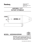
SERVICE MANUAL LN-9218-00.13 (REPLACES: LN-9218-00.12) February - 2013 Ransburg MICROPAK TM MODEL: LECU5004 IMPORTANT: Before using this equipment, carefully read SAFETY PRECAUTIONS, starting on page 1, and all instructions in this manual. Keep this Service Manual for future reference. Service Manual Price: $50.00 (U.S.) MicroPak Ransburg NOTE: This manual has been changed from revision LN-9218-00.12 to revision LN-9218-00.13. Reasons for this change are noted under “Manual Change Summary” inside the back cover of this manual. LN-9218-00.13 Ransburg MicroPak - Contents CONTENTS PAGE SAFETY: 1-5 SAFETY PRECAUTIONS .......................................................................................................1 HAZARDS / SAFEGUARDS ...................................................................................................2-5 INTRODUCTION: 6-7 GENERAL DESCRIPTION .....................................................................................................6 SAFETY FEATURES ..............................................................................................................6 DISPLAYS ..............................................................................................................................6 SPECIFICATIONS ..................................................................................................................6-7 INSTALLATION: 8-12 CONNECTIONS .....................................................................................................................8-12 OPERATION: 13-28 OPERATOR CONTROL .........................................................................................................13 MODES OF OPERATION / CONFIGURATION .....................................................................13-17 VERSION 3.8 SOFTWARE ....................................................................................................17 VERSION 3.9 SOFTWARE ....................................................................................................17 SWITCH SETTINGS ..............................................................................................................18 SWITCH CONFIGURATION ..................................................................................................19 INPUT / OUTPUT SIGNALS ..................................................................................................20-23 MICROPAK NODE ADAPTER PLC I/O ..................................................................................23-27 DIAGNOSTICS .......................................................................................................................28 MAINTENANCE: 29-31 TROUBLESHOOTING ...........................................................................................................29 OHM METER MEASUREMENTS / CASCADE ......................................................................30 OHM METER MEASUREMENTS FOR RANSPAK 1000 CASCADE ....................................31 PARTS IDENTIFICATION: 32-33 MICROPAK APPLICATION TABLE ....................................................................................... 32 MICROPAK PARTS LIST ...................................................................................................... 33 WARRANTY POLICIES: 34 LIMITED WARRANTY ............................................................................................................34 LN-9218-00.13 Ransburg MicroPak - Safety SAFETY SAFETY PRECAUTIONS Before operating, maintaining or servicing any Ransburg electrostatic coating system, read and understand all of the technical and safety literature for your Ransburg products. This manual contains information that is important for you to know and understand. This information relates to USER SAFETY and PREVENTING EQUIPMENT PROBLEMS. To help you recognize this information, we use the following symbols. Please pay particular attention to these sections. A WARNING! states information to alert you to a situation that might cause serious injury if instructions are not followed. A CAUTION! states information that tells how to prevent damage to equipment or how to avoid a situation that might cause minor injury. A NOTE is information relevant to the procedure in progress. While this manual lists standard specifications and service procedures, some minor deviations may be found between this literature and your equipment. Differences in local codes and plant requirements, material delivery requirements, etc., make such variations inevitable. Compare this manual with your system installation drawings and appropriate Ransburg equipment manuals to reconcile such differences. ! WARNING The user MUST read and be familiar with the Safety Section in this manual and the Ransburg safety literature therein identified. This manual MUST be read and thoroughly understood by ALL personnel who operate, clean or maintain this equipment! Special care should be taken to ensure that the WARNINGS and safety requirements for operating and servicing the equipment are followed. The user should be aware of and adhere to ALL local building and fire codes and ordinances as well as NFPA-33 SAFETY STANDARD, LATEST EDITION, prior to installing, operating, and/or servicing this equipment. ! WARNING The hazards shown on the following pages may occur during the normal use of this equipment. Please read the hazard chart beginning on page 2. Careful study and continued use of this manual will provide a better understanding of the equipment and process, resulting in more efficient operation, longer trouble-free service and faster, easier troubleshooting. If you do not have the manuals and safety literature for your Ransburg system, contact your local Ransburg representative or Ransburg. 1 LN-9218-00.13 Ransburg MicroPak - Safety AREA HAZARD Spray Area Fire Hazard Tells where hazards may occur. Tells what the hazard is. Improper or inadequate operation and maintenance procedures will cause a fire hazard. Protection against inadvertent arcing that is capable of causing fire or explosion is lost if any safety interlocks are disabled during operation. Frequent Power Supply or Controller shutdown indicates a problem in the system requiring correction. SAFEGUARDS Tells how to avoid the hazard. Fire extinguishing equipment must be present in the spray area and tested periodically. Spray areas must be kept clean to prevent the accumulation of combustible residues. Smoking must never be allowed in the spray area. The high voltage supplied to the atomizer must be turned off prior to cleaning, flushing or maintenance. When using solvents for cleaning: •• Those used for equipment flushing should have flash points equal to or higher than those of the coating material. •• Those used for general cleaning must have flash points above 100°F (37.8°C). Spray booth ventilation must be kept at the rates required by NFPA-33, OSHA, country, and local codes. In addition, ventilation must be maintained during cleaning operations using flammable or combustible solvents. Electrostatic arcing must be prevented. Safe sparking distance must be maintained between the parts being coated and the applicator. A distance of 1 inch for every 10KV of output voltage is required at all times. Test only in areas free of combustible material. Testing may require high voltage to be on, but only as instructed. Non-factory replacement parts or unauthorized equipment modifications may cause fire or injury. If used, the key switch bypass is intended for use only during setup operations. Production should never be done with safety interlocks disabled. Never use equipment intended for use in waterborne installations to spray solvent based materials. The paint process and equipment should be set up and operated in accordance with NFPA33, NEC, OSHA, local, country, and European Health and Safety Norms. LN-9218-00.13 2 Ransburg MicroPak - Safety AREA Tells where hazards may occur. Spray Area HAZARD Tells what the hazard is. SAFEGUARDS Tells how to avoid the hazard. Explosion Hazard Improper or inadequate operation and maintenance procedures will cause a fire hazard. Protection against inadvertent arcing that is capable of causing fire or explosion is lost if any safety interlocks are disabled during operation. Frequent Power Supply or Controller shutdown indicates a problem in the system requiring correction. Electrostatic arcing must be prevented. Safe sparking distance must be maintained between the parts being coated and the applicator. A distance of 1 inch for every 10KV of output voltage is required at all times. Unless specifically approved for use in hazardous locations, all electrical equipment must be located outside Class I or II, Division 1 or 2 hazardous areas, in accordance with NFPA-33. Test only in areas free of flammable or combustible materials. The current overload sensitivity (if equipped) MUST be set as described in the corresponding section of the equipment manual. Protection against inadvertent arcing that is capable of causing fire or explosion is lost if the current overload sensitivity is not properly set. Frequent power supply shutdown indicates a problem in the system which requires correction. Always turn the control panel power off prior to flushing, cleaning, or working on spray system equipment. Before turning high voltage on, make sure no objects are within the safe sparking distance. Ensure that the control panel is interlocked with the ventilation system and conveyor in accordance with NFPA-33, EN 50176. Have fire extinguishing equipment readily available and tested periodically. General Use and Maintenance Improper operation or maintenance may create a hazard. Personnel must be given training in accordance with the requirements of NFPA-33, EN 60079-0. Personnel must be properly trained in the use of this equipment. Instructions and safety precautions must be read and understood prior to using this equipment. Comply with appropriate local, state, and national codes governing ventilation, fire protection, operation maintenance, and housekeeping. Reference OSHA, NFPA-33, EN Norms and your insurance company requirements. 3 LN-9218-00.13 Ransburg AREA Tells where hazards may occur. Spray Area / High Voltage Equipment MicroPak - Safety HAZARD Tells what the hazard is. SAFEGUARDS Tells how to avoid the hazard. Electrical Discharge There is a high voltage device that can induce an electrical charge on ungrounded objects which is capable of igniting coating materials. Inadequate grounding will cause a spark hazard. A spark can ignite many coating materials and cause a fire or explosion. Parts being sprayed and operators in the spray area must be properly grounded. Parts being sprayed must be supported on conveyors or hangers that are properly grounded. The resistance between the part and earth ground must not exceed 1 meg ohm. (Refer to NFPA-33.) Operators must be grounded. Rubber soled insulating shoes should not be worn. Grounding straps on wrists or legs may be used to assure adequate ground contact. Operators must not be wearing or carrying any ungrounded metal objects. When using an electrostatic handgun, operators must assure contact with the handle of the applicator via conductive gloves or gloves with the palm section cut out. NOTE: REFER TO NFPA-33 OR SPECIFIC COUNTRY SAFETY CODES REGARDING PROPER OPERATOR GROUNDING. All electrically conductive objects in the spray area, with the exception of those objects required by the process to be at high voltage, must be grounded. Grounded conductive flooring must be provided in the spray area. Always turn off the power supply prior to flushing, cleaning, or working on spray system equipment. Unless specifically approved for use in hazardous locations, all electrical equipment must be located outside Class I or II, Division 1 or 2 hazardous areas, in accordance with NFPA-33. LN-9218-00.13 4 Ransburg MicroPak - Safety AREA Tells where hazards may occur. Electrical Equipment HAZARD Tells what the hazard is. Tells how to avoid the hazard. Electrical Discharge An electrical arc can ignite coating materials and cause a fire or explosion. Unless specifically approved for use in hazardous locations, the power supply, control cabinet, and all other electrical equipment must be located outside Class I or II, Division 1 and 2 hazardous areas in accordance with NFPA-33 and EN 50176. Turn the power supply OFF before working on the equipment. Test only in areas free of flammable or combustible material. Testing may require high voltage to be on, but only as instructed. Production should never be done with the safety circuits disabled. Before turning the high voltage on, make sure no objects are within the sparking distance. Certain material may be harmful if inhaled, or if there is contact with the skin. Follow the requirements of the Material Safety Data Sheet supplied by coating material manufacturer. High voltage equipment is utilized in the process. Arcing in the vicinity of flammable or combustible materials may occur. Personnel are exposed to high voltage during operation and maintenance. Protection against inadvertent arcing that may cause a fire or explosion is lost if safety circuits are disabled during operation. Frequent power supply shutdown indicates a problem in the system which requires correction. Toxic Substances SAFEGUARDS Adequate exhaust must be provided to keep the air free of accumulations of toxic materials. Use a mask or respirator whenever there is a chance of inhaling sprayed materials. The mask must be compatible with the material being sprayed and its concentration. Equipment must be as prescribed by an industrial hygienist or safety expert, and be NIOSH approved. Spray Area Explosion Hazard – Incompatible Materials Halogenated hydrocarbon solvents for example: methylene chloride and 1,1,1,-Trichloroethane are not chemically compatible with the aluminum that might be used in many system components. The chemical reaction caused by these solvents reacting with aluminum can become violent and lead to an equipment explosion. 5 Aluminum is widely used in other spray application equipment - such as material pumps, regulators, triggering valves, etc. Halogenated hydrocarbon solvents must never be used with aluminum equipment during spraying, flushing, or cleaning. Read the label or data sheet for the material you intend to spray. If in doubt as to whether or not a coating or cleaning material is compatible, contact your coating supplier. Any other type of solvent may be used with aluminum equipment. LN-9218-00.13 Ransburg MicroPak - Introduction INTRODUCTION GENERAL DESCRIPTION The MicroPakTM Controller, in conjunction with an appropriate cascade, is used to provide high voltage for electrostatic application equipment. The controller is packaged in a single, 3.2 inch wide Eurocard module, and thus consumes less than 1/4 of the available space in a 19 inch rack. In RansPakTM 1000 mode, beginning with software version 3.2, the signal used for the current (µA) display is conditioned to subtract out the internal cascade “bleeder” current and thus display the actual output current. The MicroPak uses a combination of proven high voltage generation technology including microprocessor-based control with diagnostic and communication functions. The processor circuitry provides the maximum in applicator transfer efficiency, while maintaining the maximum safety when used in conjunction with FM listed applicators. SPECIFICATIONS SAFETY FEATURES When used with FM listed applicators, the MicroPak provides the ultimate in operational safety. The microprocessor circuits allow the use of output load curve control, which limits the high voltage output to safe levels, even with the controls set at maximum levels, and does so without a hard shut down. The Over current set point, which can be monitored on the µa Display by pressing the SET push-button and holding for one second, does provide a hard shutdown if the output current exceeds the set point. The kV set point is also displayed on the kV display when the SET push-button is pressed for one second. DISPLAYS The front panel displays for output voltage and current indicate the outputs from the cascade of direct charge applicators or the probe tip voltage in the case of indirect charge applicators. They are derived from feedback signals in the low voltage cable between the controller and the cascade. LN-9218-00.13 (At Sea-Level Conditions) Environmental / Physical Temp. Operating: (0o to 55o C) Storage: (-40o C to 85o C) Humidity: Size: (95% Non-Condensing) 100 X 160mm Eurocard module, total width 3.2 in. (one module) Electrical Requirements Power Required: (per MicroPak) 24 VDC at 2.5A (fully loaded output), HP404, RP404, and HP505 Cascades 28 VDC at 6A (fully loaded output), RansPak 1000 (RP1000) Cascade Note: 24 VDC and 28 VDC power supplies must be regulated and have overcurrent (40%) and overvoltage (20%) protection. 6 Ransburg MicroPak - Introduction Electrical MicroPak with HP404 / RP404 Cascades Controls: 1. All communication to Controller by CANBus 2. Direct A-B RIO communication via additional Node Adapter Module (Part# LECU4012) or Serial Node Adapter + Module (Part #78553) (One Node Adapter per rack) 3. Discrete signals available via additional I/O Module (Part# 76037) in place of Node Adapter with levels as shown below Analog In: (0-10 VDC or 4-20 mA DC) kV Set Current Set (Overcurrent Setpoint) (Di/dt Sensitivity) Analog Out: (0-10 VDC) OUTPUT kV OUTPUT CURRENT Discrete Out: (Dry Contact) HV ON FB FAULT HV READY OVER CURRENT FAULT LOCAL HV RESET Discrete In: (24 VDC Source or Sink) HV OFF HV ON FLUID TRIGGER AIR TRIGGER / SEQUENCER START Trigger Out: (24 VDC, 150 mA Maximum) (For EFM Gun) AIR TRIGGER 7 Output: 100 kV @ 0 µA 125 µA @ 0 kV Cascade Size: HP404 1.50” X 1.56” x 7.0” RP404 4” X 4” X 12” MicroPak With RP1000 Cascade Output: 100 kV, 1000 µA (75% Duty Cycle) Cascade Size: 4” X 4” X 12” MicroPak With LEPS5002 Cascade Output: 100 kV, 1000 µA (75% Duty Cycle) Cascade Size: 14” X 12” X 12” MicroPak With HP404 FM Cascade Output: 100 kV, 0 µA (85 µA Max.) Cascade Size: 1.50” X 1.56” X 7.0” MicroPak With HP505 Cascade Output: 100 kV @ 0 µA 240 µA @ 0 kV Cascade Size: 1.50” X 1.56” X 7.0” LN-9218-00.13 Ransburg MicroPak - Installation INSTALLATION CONNECTIONS - For MicroPak with HP404, RP404 & HP505-+24 VDC - For MicroPak with RP1000 - +28 VDC Input Power This must be supplied from a regulated power supply. Connection is made at J2 for +24/28 V, 24/28 VRET, and Factory Ground. The 24/28 VDC supply is protected against excessive current draw by an automatically resetting fuse internal to the MicroPak. In case of a current draw over 6 A, the fuse will open circuit and automatically reset when 24/28 VDC power is removed. ! CAUTION The 24VRET must be connected to Factory Ground at the +24 VDC power supply (see Figures 1 and 2). Node Adapter / Discrete I/O Power When a Node Adapter or Discrete I/O Module is used, power must be supplied to it via J10. Connect +24 VDC to J10-1, and 24 VRET to J10-2 (see Figures 1 and 2). Output To Cascade HP404, HP505 & RP404 Make connections to J3 per Figure 1. Use the appropriate cable assemblies for HP404 / HP505 (see MicroPak parts list at back of this manual). Use only the A12971 cable assembly for RP404. RP1000 Make connections to J3 per Figure 2. Use only the 74947 cable assembly. LN-9218-00.13 The two wire braids must be connected to a dedicated HV power supply ground bus. This bus must be isolated from the system ground bus except at the termination point to earth ground. ! WARNING If these connections are not made in this manner, damage will result to system electronic components, and system safety may be compromised. Remote I/O If applicable, connect Remote I/O Blue to J5-B, Shield to J5-S, and Clear to J5-C. CANBus Provide a jumper from the MicroPak mother board connector J8 (CAN) to pneumatic mother board connector J4. This should be done with a short section of shielded pair cable while observing the (+) and to (+) convention. See Figure 3. In Node Adapter applications, provide additional jumper wires from pneumatic mother board to the next pneumatic mother board, up to a maximum of four (4) mother boards. . Interlock Terminal strip J6 provides a connection point for system interlock to prevent generation of high voltage. Terminal J6-1 must be connected to J6-2 by jumper or voltage free contact in order to make the High Voltage Ready (HVRDY) mode. If this connection is momentarily broken, HVRDY must be reset. Make no connection to J6-3 before reading “HV On Control” in the “Operation” section of this manual. 8 MicroPak - Installation MicroPak Grounding 1. The Power Supply must be referenced to true earth ground at only one point. (Refer to Figures 1, 2, and 3 for Grounding Connections.) ! CAUTION Separate ground connections MUST be used for grounding the part and the Power Supply. 2. Shields from the low voltage cable must be connected to a bus isolated from panel ground, then by a 3/4” braid to the building steel or ground grid if available. 3. The 24 or 28 VDC power supply common should be connected to the factory ground input for safety, even though they are connected to the isolated bus via the MicroPak motherboard. Ransburg 2. The feedback signals for kV and µA are developed with respect to the cascade ground. If the cascade ground were routed only to earth ground via the above mentioned shields, the feedback conditioning circuitry would have to depend on the panel ground or power supply common to get a ground reference for the feedback signals. This means the low level return current for these signals would have to flow to earth ground and back to the controller via factory ground or power supply common. This adds large amounts of noise to these low voltage signals. 3. A great deal of testing under high voltage corona conditions has confirmed that this cascade ground should be connected directly at a single point to the signal ground plane of the MicroPak power supply controller. This single point method maintains a “clean” feedback signal while limiting the amount of high frequency noise that is dumped onto the signal ground and therefore other grounds in the overall system, such as the PLC. MicroPak Grounding Theory 1. The low voltage cable has a large amount of high frequency noise on the shields and grounds from being in proximity to the high voltage generator. Taking these grounds directly to earth ground or a ground grid through good high frequency conductors (braid) keeps this high frequency noise from interfering with the low voltage control circuitry. This is why they are isolated from panel ground. This is consistent with standard practice for lightning protection. (See NFPA-70 and NFPA -780.) 9 LN-9218-00.13 Ransburg MicroPak - Installation Figure 1: MicroPak Controller w/ HP404, RP404 & HP505 Cascade Figure 2: MicroPak Controller W/LEPS5002 or 74793 Cascade (RansPak 1000) LN-9218-00.13 10 11 ALL CANBUS JUMPERS TO BE CONNECTED WITH SHIELDED CABLE FOR NODE ADAPTER APPLICATIONS, PROVIDE ADDITIONAL CANBUS JUMPER TO NEXT PNEUMATIC MOTHERBOARD UP TO A MAXIMUM OF 4 MOTHERBOARDS. MicroPak - Installation Ransburg Figure 3: Proper Power Supply and Grounding Connections LN-9218-00.13 Ransburg MicroPak - Installation Figure 4: Typical MicroPak / RP1000 / RP404 Layout LN-9218-00.13 12 Ransburg MicroPak - Operation OPERATION OPERATOR CONTROL Operator control may be accomplished by: (1) front panel controls (2) CANBus serial communication (3) node adapter (4) discrete analog and digital I/O 1. Front panel controls are provided for power on, high voltage set point, over current set point, di/ dt sensitivity, and high voltage on/off. 2. CANBus connection provides expanded control and monitor functions shown as analog in/out and discrete in/out in the MicroPak Specifications. 3. Node Adapter connection converts an external serial protocol, such as Allen-Bradley Remote I/O, to CANBus for communication to the MicroPak. The format for Allen-Bradley communication is shown under “MicroPak Node Adapter PLC I/O” in the “Operation” section of this manual. 4. Discrete I/O connections are made via the 76111-xx I/O cable which connects to connector J12. The 76111 connector must be secured to the J12 connector shroud by the two screws on the connector body. The pin-out of the discrete signals begins on page 14. The Discrete I/O Module switch SW2, position 1 must be set for the cascade in use with the MicroPak. For RP1000 or LEPS5002 application, SW2-1 is OFF. For HP404, RP404 and HP505 application, SW2-1 is ON. 13 MODES OF OPERATION / CONFIGURATION (Refer to Figure 6) Local / Remote The Local/Remote switch located on the front panel determines the source for the setpoints for kV, di/ dt and Over Current. In the Local Position, these come from the front panel controls labeled kV and µA. In the Remote position, these come from the Node Adapter, directly from CANBus, or from the Discrete I/O Module, except as described below. The MicroPak can be configured for a fixed (internal adjustment) µA (overload) setpoint while accepting a remote analog kV setpoint. To enable this feature, see figure 6. In this configuration, the µA setpoint comes from pot R21 at the top of the Process PCB instead of the external analog signal. Holding in the “SET” button will display the analog kV setpoint and the fixed (internal) µA setpoint. HV Cascade / Regulation Mode The MicroPak is factory configured for HP404, RP404, or HP505 cascade applications or applications using the 74793-XX or LEPS5002 HV units. In addition, the cascades may be operated in voltage regulation or current regulation modes. Each configuration has a specific part number as shown in the “Parts Identification” section of this manual. HV On Control Remote When remote HV On controls are used, SW3-3 should be set to ON. Motherboard terminal J6-3 should be jumpered to J6-2 to enable the HV Ready mode. LN-9218-00.13 Ransburg ! MicroPak - Operation WARNING In no case should the J6-3 to 2 jumper be used with SW3-3 in the OFF position. (This will turn HV On any time Unit Power is On.) Front Panel When front panel controls are used, SW3-3 can be set to OFF so that the HV ON mode is always enabled, meaning that anytime the HV Ready mode is entered, HV is turned on. This allows the front panel kV switch to enable the HV Ready and HV on modes at the same time. Remote / Sequenced The same connections apply here as for the Remote mode. If the Sequence Rotary Switch (see Figure 7) is set to a non-zero position, the HV and fluid trigger are turned on and off in the sequence described in Figures 5a & 5b. The sequence is initiated by activating the air trigger signal when the sequence rotary switch is in a non-zero position. ! CAUTION Be sure that no connection is made to Motherboard terminal J6-3. Switch Setting Fluid Delay (A) milliseconds HV Delay (B) milliseconds 0 1 2 3 4 5 6 7 8 9 No Sequence 0 150 250 0 100 150 200 300 400 No Sequence 0 0 0 50 50 50 50 50 50 Figure 5a: Sequence Mode Operation Figure 5b: Sequence Mode Operation (Not for Indirect Charge Mode) LN-9218-00.13 14 Ransburg MicroPak - Operation CANBus Address The MicroPak must be set at a non-zero CANBus address when CANBus communication is used, whether from an outside CANBus source, Discrete I/O Module or Node Adapter. When front panel controls are used, SW3-3 can be set to OFF so that the HV ON mode is always enabled, meaning that anytime the HV Ready mode is entered, HV is turned on. This allows the front panel kV switch to enable the HV Ready and HV On modes at the same time. The address is set in binary by Switch SW7, labeled “Node Address”, positions 2-4 with position 4 being the LSB (see Figure 6). In applications where Discrete I/O Module is used, the MicroPak must be set at CANBus address 01. In Node Adapter applications, the MicroPak(s) must be set to a CANBus address corresponding to the locations in the PLC I/O tables. Each MicroPak must have a unique address from 01-04. Di/dt Operating Mode A di/dt (rate of change in current with respect to time) safety overload function can be used in addition to the fixed current overload. This is an adjustable setting which determines the maximum current increase that can occur during a fixed time period. The di/dt detection feature will improve the ability of the power supply to prevent discharges to the applicator when a grounded object is approaching at rates greater than approximately 4 inches per second. Slower rates of approach are typically sensed by the fixed current overload if properly set. The di/dt and fixed current overloads must be set correctly to prevent discharges when using metal (unlisted) applicators. MICROPAK di/dt SENSITIVITY LEVELS SLP # 0 1 2 3 4 5 6 7 8 9 Sensitivity µA/100m Sec. 8.0 10.0 15.0 20.0 25.0 30.0 35.0 40.0 50.0 60.0 The di/dt overload is disabled for the time required to ramp voltage from a lower requested kV to a higher value. This time will vary based on the magnitude of the kV increase. The HV “ON” LED will flash ON and OFF during each di/dt inhibit period (Local mode only). When the applicator is moved quickly (e.g., robot), SLP #7, #8 or #9 should be used to avoid nuisance faults. For di/dt modes of operation, the di/dt function is enabled by setting SW7-6, located on the MicroPak Process PCB to the ON (down position). For all other applications where di/dt does not apply, SW7-6 must be set to the OFF (up) position. This is the default setting for all MicroPak control unit models that do not have the di/dt function. ! CAUTION Separate ground connections MUST be used for grounding the part and the Power Supply. The MicroPak controller monitors the output current and compares the value to the rate of change set- point (SLP) provided by the user setting. (See the “MicroPak Di/dt Sensitivity Chart” for corresponding rates of change for each SLP setting number.) 15 LN-9218-00.13 Ransburg To Read the Di/dt Setting Push the “SET” push-button twice within one second. The kV display will read “SLP” and the µA display will indicate a number between 0 and 9. This number represents different levels of di/ dt sensitivity with 0 being most sensitive. If the “SET” push-button is not pressed again, the µA display will automatically return to normal output current display. MicroPak - Operation Determining if a Di/dt Overload Occurred The “OVER” LED (overload) will flash on and off if a di/dt caused an overload, otherwise the “OVER” LED will stay on continuously if a fixed current overload occurred. This will help determine the type of high voltage fault that occurred. Voltage Boost Mode To Adjust the Di/dt Value Local Mode Once a di/dt sensitivity level is displayed, it can be changed by pressing the “SET” button again and holding in. The sensitivity level will increment slowly. Once the desired level is displayed (0-9), then release the “SET” button. The new value is stored in memory when the “SET” push-button is released. This setting should be set as sensitive as possible (smallest di/dt value) without nuisance overloads occurring. This should be done with paint loaded and normal production parts present. The MicroPak software has been revised to provide two voltage correction modes when configured for the HP404 cascade. The purpose of this change is to compensate for the voltage drop in the cascade’s current limiting resistor. Position 1 (see Figure 6), voltage correction 1 mode, provides correction when the output current is always below 50 µA. Position 2 (see Figure 6), voltage correction 2 mode is the default mode and provides correction when the output current runs or may range above 50 µA. Voltage Regulation Remote Mode In remote mode, the above sensitivity levels are set by the numbers 0 to 9 in a Block Transfer Write (BTW) similiar to the method for setting the setpoint for kV. The BTW information is shown in the “MicroPak Node Adapter PLC/IO” in the “Operation” section. The di/dt sensitivity level in Minimized Remote Mode (Remote mode where SW3-1 is in OFF position) will still be set as in Local mode. In this mode, the kV setpoint is still remote, and the µA setpoint is still from internal pot R21. The di/dt function can be inhibited when needed during the application process to avoid nuisance shutdown. To understand the details of using this feature with either the Discrete I/O Module or Serial Node Adapter, reference the appropriate I/O tables further back in this Operation section. LN-9218-00.13 To date, the most common type of output regulation for electrostatic painting applications is voltage regulation. This means sensing the output voltage, comparing this to the voltage setpoint, and adjusting the cascade drive to maintain the output equal to the setpoint. In this mode the current varies, depending on the load, up to the Current Setpoint where the unit switches to Over Current, turning off the output. Current Regulation The MicroPak is also capable of current regulation which is desired for some applications. In this mode the functions of voltage and current are reversed from the voltage regulation mode. This means sensing the output current, comparing this to the current setpoint, and adjusting the cascade drive to maintain the current output equal to the current setpoint. In this mode the voltage varies, 16 MicroPak - Operation Ransburg depending on the load, up to the kV Setpoint. The operation is different than the voltage regulation mode in that, when the kV Setpoint is reached, there is no “over-voltage” function and the unit maintains the output voltage at the setpoint and allows the current to drop. It stays in this mode until the load changes such that the current increases up to its setpoint, then it limits at the setpoint and the voltage drops. The big difference between voltage and current regulation is that the Current Setpoint is used to set a limit and not an Over Current shutdown point. The actual Over Current threshold is set 30% (SW7-5 OFF) above the Current Setpoint so that in a dynamic situation where the current can actually rise above the limit point, the Over Current function is still active. VERSION 3.8 SOFTWARE This version adds some switch settings for the new HP505 cascade. The HP404 settings having zero voltage corrections factors (“K”) may be used for HP505. For voltage correction using the HP505, switches must be set per Figure 6. Note that this changes the function of SW7-1 from node addressing to cascade selection. It is not needed for node addressing. VERSION 3.9 SOFTWARE This version adds appropriate switch settings for the new RP404 cascade. These can be found in Figure 6. 17 LN-9218-00.13 Ransburg MicroPak - Operation Figure 6: Switch Settings LN-9218-00.13 18 Ransburg MicroPak - Operation MicroPak Controller Output Board Rotary Sequence Switch Location MicroPak Controller Process Board SW3 Node Address Switch (SW7) MicroPak Controller Process Board Figure 7: Switch Configuration 19 LN-9218-00.13 Ransburg MicroPak - Operation INPUT / OUTPUT SIGNALS Discrete I/O Mode The Discrete I/O Module may be used to connect discrete signals to one MicroPak Controller and one Atomizer Turbine Speed Control Module. Use the 76111-xx DIO cable assembly to make connections. The following I/O signals are available for control and monitoring via the discrete I/O module. SW2 1 2 8 Function Cascade Speed Command / Feedback Scaling Analog Input Offset OFF ON RP1000 0-50 krpm 0-10 HP404, RP404, HP505 0-100 krpm 2-10 (4-20) ANALOG INPUTS Wire Color J7 Pin YEL 5A BLA 28C BLU 6A Over Current Setpoint (ISET) - 0-1000 µA (1000 mode) or 0-250µA (HP404, RP404, or HP505 mode) BLA 28A OC Set Ground (ISETGND) BRN 4C Atomizer Speed Setpoint (see SW2-2 position for scaling) BLA 3A Speed Setpoint Ground WHT 3C Di/dt Sensitivity 0 to 9 Scale (ø equals the most sensitive position) Signal Description High Voltage Setpoint (KVSET) - 0-100 kV HV Set Ground (KVSETGND) Note: For DIO module 76037-00 and 76037-03, analog inputs are 0-10 VDC, 150 k Ohm input impedance.For DIO module 76037-02 and 76037-04, analog inputs are 4-20 mA, 249 Ohm input impedance. (Input / Output Signals Continued On Next Page) LN-9218-00.13 20 Ransburg MicroPak - Operation INPUT / OUTPUT SIGNALS (Cont.) ANALOG OUTPUTS (3mA Max.) Signal Description Wire Color J7 Pin GRN 14C High Voltage Output Level (KVFB) - 0-10 VDC=0-100 kV BLA 17A HV Out Ground (KVFBGND) WH 6C Current Output Level (IFB) - 0-10 VDC=0-1000 µA (1000 mode) or 0-10 VDC=0-250µA (HP404, RP404, or HP505 mode) BLA 8A Current Output Ground (IFBGND) RED 7C Atomizer Speed Feedback (see SW2-2 position for scaling) BLA 7A Speed/Pressure Feedback Ground BLA/RED 8C Drive Pressure Feedback - 0-10 VDC = 0-100 psi DISCRETE INPUTS (24 VDC Source or Sink Referenced to 18A (WH/BLA/RED), 14A (RED/GRN), or 13A (BLU/RED) For Source: Set DIO Module Jumpers E5 and E6 to 2-3 For Sink: Set DIO Module Jumper E5 and E6 to 1-2 Wire Color J7 Pin Signal Description BLU/BLA 20C High Voltage On (HVON) - If HVRDY is active, supplying 24 VDC causes high voltage to be present at cascade output. OR/BLA 19C High Voltage Reset (HVOFF) - Supplying 24 VDC turns off HV, over-riding HVON signal, or resets fault conditions. RED/BLA 17C Fluid Trigger (FLTRIG) - Supplying 24 VDC causes fluid trigger to EFM gun to be active with di/dt activation delayed 5 seconds. WH/RED 16C Air Trigger (AIRTRIG) - Supplying 24 VDC causes air trigger to EFM gun to be active. In Sequence Mode (sequence rotary switch in non-zero position), starts programmed sequence of air trigger, fluid trigger and HV on. ORG 15C Di/dt Inhibit - Supplying 24 VDC causes di/dt to be disabled. BLU/WH 9C Bell Spin Enable - 24 VDC must be supplied to send the speed setpoint to the Atomizer. This may also be used as a fault reset, leaving the speed command constant. (Input / Output Signals Continued On Next Page) 21 LN-9218-00.13 Ransburg MicroPak - Operation INPUT / OUTPUT SIGNALS (Cont.) DISCRETE OUTPUTS (Contact Ratings: 2 A @ 28 VDC Resistive, 0.5 A @ 120 VAC Resistive, One Side Common With 30C, White/Black Wire) Wire Color J7 Pin Signal Description RED 26A Bell Running - Indicates that Drive air pressure is being supplied to the bell. OR/RED 26C High Voltage Ready (HVRDYB) - Indicates interlock is satisfied, High Voltage Reset is not active and neither Over Current Fault or Feedback Fault is present. In High Voltage Ready mode, a signal to the High Voltage ON input will cause High Voltage to come on. GRN/BLA 27C High Voltage On (HVONB) - Indicates High Voltage is on. BLA/WH/ RED 24A Over Current Fault or di/dt Fault (OLB) - Indicates either the DC output current has exceeded the setpoint or the current rate of rise has exceeded the di/dt sensitivity setpoint. OR/GRN 22A Feedback Fault (FBFLTB) - Indicates abnormal signal levels are present on the kV and/or Current Feedback signals from the cascade. (See “Diagnostic” in the “Operation” section for a detailed description.) RED/WH 22C Local (LOC) - Indicates front panel switch is in “Local” position. In “Local”, the setpoints for kV and Current are received from the front panel controls and not from remote inputs. N/A * Sequence (SEQB) - Indicates Sequence rotary switch is in a “Non-Zero” position. (Sequence Mode Timing Diagram is shown in Figure 4.) N/A * Fluid Trigger Active (FLTRIGB) - Indicates the Fluid Trigger output to the EFM gun is active; applies in both sequenced and non-sequenced modes. N/A * Air Trigger Active (AIRTRIGB) - Indicates Air Trigger output to EFM gun is active. BLA 1A Overspeed Fault - Indicates module has shut down drive to bell because speed is 10 krpm above setpoint. GRN 4A Underspeed Fault - Indicates module has shut down drive to bell because speed is 5 krpm under setpoint. BLU 12A Loss of Feedback Fault - Indicates module has shut down drive to bell because the maximum time allowed between feedback pulses has been exceeded. * Status signal available in Node Adapter applications only. (Input / Output Signals Continued On Next Page) LN-9218-00.13 22 Ransburg MicroPak - Operation INPUT / OUTPUT SIGNALS (Cont.) DISCRETE OUTPUTS (Cont.) (Contact Ratings: 2 A @ 28 VDC Resistive, 0.5 A @ 120 VAC Resistive, One Side Common With 30C, White/Black Wire) Wire Color J7 Pin Signal Description BLA/WH 23C Invalid Data Fault - Indicates module has shut down drive to bell because speed setpoint is above the operating range of the bell. GRN/WH 24C Low Bearing Air Fault - Indicates module has shut down drive to bell because bearing air pressure is below the level set by Serial Atomizer switch SW2-7 and -8. GRN/BLA/WH 25C Speed out of Tolerance - Indicates bell speed is outside the window of ±5% of setpoint. This is a status signal only and does not shut down drive to bell. R/BLA/WH 31A 24 VDC utility output, may be used to power relay contact common (30C), 0.1 Amps Max. * Status signal available in Node Adapter applications only. MICROPAK NODE ADAPTER PLC I/O - MicroPak Mode DISCRETE OUTPUT CONFIGURATION 23 Bit Module 0/00-07 0/10 0/11 0/12 0/13 0/14-17 1/00 1/01 1/02 1/03 1/04 1/05 1/06 1/07 1/10 1/11 1/12 1/13 1/14 1/15 1/16 1/17 (Not Used) MicroPak #1 MicroPak #2 MicroPak #3 MicroPak #4 (Not Used) MicroPak #1 MicroPak #1 MicroPak #1 MicroPak #1 MicroPak #2 MicroPak #2 MicroPak #2 MicroPak #2 MicroPak #3 MicroPak #3 MicroPak #3 MicroPak #3 MicroPak #4 MicroPak #4 MicroPak #4 MicroPak #4 Output ---Di/dt Inhibit Di/dt Inhibit Di/dt Inhibit Di/dt Inhibit ---HV On Command HV Reset Fluid Trigger / Di/dt Delay Air Trigger HV On Command HV Reset Fluid Trigger / Di/dt Delay Air Trigger HV On Command HV Reset Fluid Trigger / Di/dt Delay Air Trigger HV On Command HV Reset Fluid Trigger / Di/dt Delay Air Trigger LN-9218-00.13 Ransburg MicroPak - Operation MICROPAK NODE ADAPTER PLC I/O - MicroPak Mode (Cont.) DISCRETE OUTPUT BIT DEFINITION Bit Module 1/00 1/01 1/02 1/03 1/04 1/05 1/06 1/07 1/10 1/11 1/12 1/13 1/14 1/15 1/16 1/17 MicroPak #1 MicroPak #1 MicroPak #1 MicroPak #1 MicroPak #2 MicroPak #2 MicroPak #2 MicroPak #2 MicroPak #3 MicroPak #3 MicroPak #3 MicroPak #3 MicroPak #4 MicroPak #4 MicroPak #4 MicroPak #4 Output HV On Command HV Reset Fluid Trigger / Di/dt Delay Air Trigger HV On Command HV Reset Fluid Trigger / Di/dt Delay Air Trigger HV On Command HV Reset Fluid Trigger / Di/dt Delay Air Trigger HV On Command HV Reset Fluid Trigger / Di/dt Delay Air Trigger BLOCK TRANSFER WRITES BTW Word Module 0 1 2 3 4 5 6 7 8 9 10 11 12 13 14 15 MicroPak #1 MicroPak #1 MicroPak #1 (Not Used) MicroPak #2 MicroPak #2 MicroPak #2 (Not Used) MicroPak #3 MicroPak #3 MicroPak #3 (Not Used) MicroPak #4 MicroPak #4 MicroPak #4 (Not Used) BTW Block Configuration High Voltage Setpoint (Value of 0 - 100 corresponds to 0 - 100 kV) Current Limit Setpoint (Value of 0 - 250 corresponds to 0 - 250 µA *) Di/dt Setpoint ( 0 - 9 corresponds to max. to min. sensitivity) ---High Voltage Setpoint (Value of 0 - 100 corresponds to 0 - 100 kV) Current Limit Setpoint (Value of 0 - 250 corresponds to 0 - 250 µA *) Di/dt Setpoint ( 0 - 9 corresponds to max. to min. sensitivity) ---High Voltage Setpoint (Value of 0 - 100 corresponds to 0 - 100 kV) Current Limit Setpoint (Value of 0 - 250 corresponds to 0 - 250 µA *) Di/dt Setpoint ( 0 - 9 corresponds to max. to min. sensitivity) ---High Voltage Setpoint (Value of 0 - 100 corresponds to 0 - 100 kV) Current Limit Setpoint (Value of 0 - 250 corresponds to 0 - 250 µA*) Di/dt Setpoint ( 0 - 9 corresponds to max. to min. sensitivity) ---- * 0-85 corresponds to 0-85 µA for HP404 FM 0-1000 corresponds to 0-1000 µA for RP1000 or LEPS5002 applications. LN-9218-00.13 24 Ransburg MicroPak - Operation MICROPAK NODE ADAPTER PLC I/O (Cont.) - MicroPak Mode BLOCK TRANSFER READS BTR Word Module 0 MicroPak #1 High Voltage Feedback (Value of 0-100 corresponds to 0-100 kV) 1 MicroPak #1 Current Feedback (Value of 0-250 corresponds to 0-250 µA *) 2 MicroPak #1 Status Word ** 3 MicroPak #2 High Voltage Feedback (Value of 0-100 corresponds to 0-100 kV) 4 MicroPak #2 Current Feedback (Value of 0-250 corresponds to 0-250 µA *) 5 MicroPak #2 Status Word** 6 MicroPak #3 High Voltage Feedback (Value of 0-100 corresponds to 0-100 kV) 7 MicroPak #3 Current Feedback (Value of 0-250 corresponds to 0-250 µA *) 8 MicroPak #3 Status Word ** 9 MicroPak #4 High Voltage Feedback (Value of 0-100 corresponds to 0-100 kV) 10 MicroPak #4 Current Feedback (Value of 0-250 corresponds to 0-250 µA *) 11 MicroPak #4 Status Word ** BTR Block Configuration BTR MODULE STATUS WORD Bit Status 00 HV Held In Reset 01 HV Ready 02 HV On 03 Di/dt Fault 04 HV Overload 05 Feedback Fault 06 Sequence 07 Local 08 Fluid Trigger Active 09 Air Trigger Active 10 Di/dt Enabled 11 kV Out of Tolerance 12 Under Current 13 Overvoltage 14 (Not Used) 15 (Not Used) * 0-85 corresponds to 0-85 µA for HP404 FM 0-1000 corresponds to 0-1000 µA for RP1000 or LEPS5002 applications. ** Reference “Atomizer Status Word” table. 25 LN-9218-00.13 Ransburg MicroPak - Operation MICROPAK NODE ADAPTER PLC I/O - Node per Bell Mode DISCRETE OUTPUT CONFIGURATION DISCRETE OUTPUT BIT DEFINITION Discrete Output Word Configuration Word (Cont.) Bit Module 00 MicroPak #1 HV On Command Output 0 (Not Used) 01 MicroPak #1 HV Reset 1 Discrete Output Bits* 02 MicroPak #1 Fluid Trigger / Di/dt Delay 03 MicroPak #1 Air Trigger 04 MicroPak #1 Di/dt Inhibit * Reference “Discrete Output Bit Definition” chart. BLOCK TRANSFER WRITES BTW Word Module BTW Block Configuration 0 MicroPak High Voltage Setpoint (Value of 0-100 corresponds to 0-100 kV) 1 MicroPak Current Limit Setpoint (Value of 0-250 corresponds to 0-250 µA*) 2 MicroPak Di/dt Setpoint ( 0 - 9 corresponds to max. to min. sensitivity) 3 (Not Used) 4 Atomizer ---Speed Command Liquid (Value of 0-50 corresponds to 0-50 krpm) Speed Command Powder (Value of 0-150 corresponds to 0-15 krpm) * 0-85 corresponds to 0-85 µA for HP404 FM 0-1000 corresponds to 0-1000 µA for RP1000 or LEPS5002 applications. BLOCK TRANSFER READS BTR Block Configuration BTR Word Module 0 MicroPak High Voltage Feedback (Value of 0-100 corresponds to 0-100 kV) 1 MicroPak Current Feedback (Value of 0-250 corresponds to 0-250 µA+) 2 MicroPak MicroPak Status Word* 3 Atomizer Atomizer Status Word** 4 Atomizer Atomizer Drive Pressure (Value of 0-60 corresponds to 0-60 psi) 5 Atomizer Atomizer Speed Liquid (Value of 0-50 corresponds to 0-50 krpm) Atomizer Speed Powder (Value of 0-150 corresponds to 0-15 krpm) * Reference “MicroPak Status Word” table. ** Reference “Atomizer Status Word” table. LN-9218-00.13 26 Ransburg MicroPak - Operation MICROPAK NODE ADAPTER PLC I/O (Cont.) - Node per Bell Mode MICROPAK STATUS WORD Bit 27 Status ATOMIZER STATUS WORD Bit Status Bearing Air (8-bits) 00 HV Held In Reset 01 HV Ready 08 Overspeed 02 HV On 09 Underspeed 03 Di/dt Fault 10 Loss of Feedback 04 HV Overload 11 Invalid Data Input 05 Feedback Fault 12 Low Bearing Air 06 Sequence 13 Bell Running 07 Local 14 Speed out of Tolerance 08 Fluid Trigger Active 15 (Not Used) 09 Air Trigger Active 10 Di/dt Enabled 11 kV Out of Tolerance 12 Under Current 13 Overvoltage 14 (Not Used) 15 (Not Used) 00-07 LN-9218-00.13 Ransburg MicroPak - Operation DIAGNOSTICS Fault Conditions These are conditions that turn off the HV ON mode, signal the operator and require an HV Reset signal before HV can be turned on again. NOTE In the Current Regulation mode, the actual threshold is 30% higher than the set point. This allows the set point to control the level at which the current is regulated without having Over Current faults. Over Current The MicroPak is designed to turn off HV anytime the output current exceeds a threshold determined by the Over Current Setpoint level. Overcurrent setpoint is important and must be set to the lowest functional setting. In an event where a HV cable should fail or an electrical discharge may occur, or if the applicator, supply lines, or other factors cause abnormal increase in current, circuit will shut off. Typical set point is 1.3 - 1.5 times the normal running current during operation. ! CAUTION FM listed current overloads to approx. 50µA above the highest observed operating current. Di/dt The Di/dt Fault monitors the rate of change of current and shuts down the High Voltage if this exceeds a threshold. The operation is fully explained in the “Operations” section. Overvoltage The Over Voltage Fault monitors output kV feedback and shuts down the High Voltage if this exceeds setpoint by more than 10 kV for more than 5 seconds. This can occur when equipment LN-9218-00.13 discharges too slowly after a voltage setpoint reduction. An overvoltage fault is indicated on the front panel by the FB led flashing on and off. FB Fault The Feedback Fault monitors the HV and Current feedback signals from the cascade for abnormal signal levels. When high voltage is off, a FB Fault indicates, in general, one of two conditions: (1) an open circuit in the connection between the controller, caused by a broken wire or bad connection, or (2) a situation where HV is actually present even though the MicroPak is not generating it, either from another HV source or because the MicroPak has been recently turned off and there is a very large amount of energy storage in the HV load, causing the HV to decay very slowly. When high voltage is on, a FB Fault indicates that there is sufficient drive being sent to the cascade but no feedback on either or both of the kV and Current feedback signals. This could be caused by a faulty or disconnected cable or a faulty cascade. HV Held In Reset This signal indicates the MicroPak is seeing an HV Reset input and cannot turn on HV until the HV Reset signal is removed. Status Indications The following indicates conditions which the operator may need to know, but do not interrupt the HV ON status: kV Out of Tolerance (RP1000 mode) This signal indicates a condition when, in HV ON status, the kV feedback is over or under the kV setpoint by 5% in direct charge modes and over by 5% or under by 15% in Indirect Charge modes. This is in effect in Remote Mode only. This condition must be present for 5 seconds before the signal goes active. Under Current (RP1000 mode) This signal indicates a condition where the output current is lower than it should be (in order to detect a failed or disconnected HV cable). This is in effect in Indirect Charge Modes only. 28 MicroPak - Maintenance Ransburg MAINTENANCE TROUBLESHOOTING The Ohm Meter Measurements for HP404, RP404, HP505 Cascades and RansPak 1000 Cascade charts are shown in the “Maintenance” section (see Figures 8 and 9) and will assist in making Ohm meter measurements through the low voltage cable for troubleshooting. Note that one table is for the HP404, RP404, HP505 cascades and one is for the RansPak 1000 cascade. Also note that measurements should be taken with the low voltage cable terminal strip disconnected from the motherboard. Troubleshooting Di/dt Faults Areas to investigate for cause: • Dirty atomizer interior or exterior • Conductive solvent residue on atomizer assembly • Moisture is inside or outside of atomizer body, causing continuity or partial continuity back to ground. 29 • Moisture inside or outside of air lines back to ground. (High humidity) • Loose high voltage connections or defective high voltage cable. • Loose ground connections or defective ground connections/wire on atomizer holder or mechanism. • Dump lines not clean or dry leading back to ground. • Target not grounded and causing arcing to ground from target. • Di/dt SLP set too sensitive for the application conditions. • 24 or 28 VDC DC Power Supply to the MicroPak is unstable. - Excessive robot tip speed near neighboring parts LN-9218-00.13 LN-9218-00.13 open ckt. open ckt. 2 don’t care 11(+) 16(+) open ckt. open ckt. open ckt. open ckt. open ckt. open ckt. 340-380 680-760 XX open ckt. open ckt. open ckt. open ckt. open ckt. 7(-) AirTrig. 19.5k-20.5k open ckt. open ckt. open ckt. open ckt. 340-380 340-380 XX 425k-550k 3-5 (2) don’t care open ckt. open ckt. open ckt. open ckt. open ckt. 680-760 XX 340-380 open ckt. open ckt. open ckt. don’t care 425k-550k XX 425k-550k open ckt. open ckt. open ckt. open ckt. open ckt. open ckt. 440k-570k 10(-) Gray Yellow 9(-) kVFB SigGnd 8(-) FluidTrig. 1. Meter reading may vary due to capacitance across pins. 2. When using a four wire HV secondary transformer, the reading should be between 19.8k - 20.2k. open ckt. 1 1 1 1 open ckt. open ckt. open ckt. open ckt. open ckt. 440k-570k open ckt. open ckt. open ckt. XX 3-4 open ckt. 3-4 XX open ckt. 2-3 2-3 open ckt. 2-3 19.5k-20.5k open ckt. open ckt. open ckt. 2-3 9(+) open ckt. 8(+) open ckt. 2-3 6(-) 5(-) open ckt. 10(+) open ckt. 7(+) 2-3 2-3 Blue Green open ckt. open ckt. 6(+) 2-3 XX DrA DrB open ckt. open ckt. 5(+) 2-3 2-3 open ckt. 4(-) Black Vct open ckt. open ckt. 4(+) XX open ckt. 3(-) Red Vct open ckt. XX open ckt. 2(-) J3 Terminal 3(+) White Wire Color 2(+) IFB Signal don’t care XX 425k-550k 3-5 (2) open ckt. open ckt. open ckt. open ckt. open ckt. open ckt. 2 11(-) Orange PLFB XX don’t care don’t care don’t care open ckt. open ckt. open ckt.1 open ckt.1 open ckt.1 open ckt.1 don’t care 16(-) Bare VctRet Ohm meter measurements in Ohms from MicroPak J3 through low voltage cable to the HP404, HP505, or RP404 cascades. Also, signals for air trigger and fluid trigger for EFM atomizer including zener barriers. Make measurements with LV cable terminal strip disconnected from MicroPak motherboard. Chart Description Ransburg MicroPak - Maintenance Figure 8: Ohm Meter Measurements for HP404, RP404, HP505 Cascade 30 31 open ckt. open ckt. open ckt. XX 0.5-2 open ckt. open ckt. 3 OC1 open ckt. XX open ckt. open ckt. OC1 2 OC open ckt. open ckt. open ckt.3 open ckt. open ckt. XX 2-4 open ckt. open ckt. open ckt. open ckt. 40k-50k XX open ckt. open ckt. open ckt. 40k-50k open ckt. open ckt. 2-4 2-4 open ckt. open ckt. open ckt. open ckt. open ckt. open ckt. open ckt. open ckt. open ckt. 3 open ckt. open ckt.3 open ckt. open ckt. open ckt. open ckt. open ckt. 1. Open circuit with forward biased diode 2. Open circuit with 2 forward biased diodes 3. Meter reading may vary due to capacitance across pins. open ckt.3 3 open ckt. open ckt. open ckt. open ckt.3 open ckt.3 XX open ckt. open ckt. OC open ckt. 3 open ckt. open ckt. open ckt. 3 300-305 open ckt. 1 open ckt. 3 1-3 1-3 open ckt. open ckt. XX 2-4 open ckt. open ckt. open ckt.3 300-305 12(-) OC1 OC 1 open ckt. XX OC1 OC 1 open ckt. open ckt. OC 2 2 OC1 13(-) Wh/Brn 11(-) W/Bla+Pur 10(-) 9(-) open ckt. XX 0.5-2 open ckt. OC1 4(-) Yellow Orange DrB Green DrRet PLFB kVFB SigGnd open ckt. OC open ckt. 3(-) 2(-) White Red Blue Wh/Org 1(-) XX open ckt. open ckt.3 open ckt.3 open ckt. open ckt. 300-305 300-305 open ckt. open ckt. 300-3051 300-3051 Vct Wire Color J3 Terminal 1(+) 2(+) 3(+) 4(+) 9(+) 10(+) 11(+) 12(+) 13(+) 14(+) 15(+) 16(+) Vct IFB DCDamp Signal OC1 OC 1 XX open ckt. OC1 OC 1 open ckt. open ckt. OC2 OC 2 open ckt. OC 1 14(-) Gray DrA Ohm meter measurements in Ohms from MicroPak J3 through low voltage cable to the RansPak 1000 Cascade. Make measurements with LV cable terminal strip disconnected from MicroPak mother board. Chart Description XX 0.5-2 XX 0.5-2 open ckt. open ckt. open ckt. open ckt. 1-3 2-4 2-4 1-3 open ckt. open ckt. open ckt.3 open ckt.3 open ckt. open ckt. open ckt.3 open ckt. 3 open ckt. 300-305 300-305 open ckt. 16(-) Brn+Wh/R VctRet 15(-) Black VctRet MicroPak - Maintenance Ransburg Figure 9: Ohm Meter Measurements for RansPak 1000 Cascade LN-9218-00.13 Ransburg MicroPak - Parts Identification PARTS IDENTIFICATION MICROPAK APPLICATION TABLE MicroPak Controller Application LECU5004-01 Aerobell 33 Robot, HP404 Voltage Regulator, ABB LECU5004-01 Aerobell 33 Powder, HP404 Voltage Regulator, ABB LECU5004-01 EFM or EFMD, HP404 Voltage Regulator, ABB LECU5004-02 RP1000, Voltage Regulator, ABB Industrial LECU5004-03 RP1000, Current Regulator, ABB Industrial LECU5004-04 Aerobell 33 Powder, HP404 Current Regulator, ABB LECU5004-11 Aerobell 33 Robot, HP404 Voltage Regulator, Ransburg LECU5004-11 Aerobell 33 Powder, HP404 Voltage Regulator, Ransburg LECU5004-11 EFM or EFMD, HP404 Voltage Regulator, Ransburg LECU5004-12 RP1000, Voltage Regulator, Ransburg LECU5004-12 RP 1000, REA III, Voltage Regulator, Ransburg LECU5004-13 RP1000, Current Regulator, Ransburg LECU5004-14 HP404 Current Regulator, Ransburg LECU5004-15 RP1000, Retrofit Aerobell II, Ransburg, w/ Di/dt LECU5004-16 RP1000, Aerobell II Indirect Voltage Regulator, Ransburg, 100m Probes W/40 meg In-Line LECU5004-17 RP100, Aerobell II Indirect Voltage Regulator, Ransburg, 160m Probes LECU5004-18 HP505, Voltage Regulator, Ransburg LECU5004-19 HP505 Current Regulated, Ransburg LECU5004-31 HP404 FM, Voltage Regulator, Ransburg LECU5004-40 RP404, Voltage Regulator, Ransburg LN-9218-00.13 32 Ransburg MicroPak - Parts Identification MICROPAK PARTS LIST Part # Description LECU5004-XX LECU4014-02 76041-XX 79008-XX A12239-XX A12241-XX A12243-XX 74947-04,05,06 A12971-XX 74793-01,02 A10560-XX Control Unit, MicroPak (See “MicroPak Application” table for appropriate dash #) Mother PCB Assembly, 1/4 Rack, Discrete Input LV Cable, HP404 Cascade (Dash # denotes length in feet) Available dash #’s are: -15, -25, -50, -75, -100 LEPS5002 75933-00 79010-01 79010-00 LECU4012-00 or 78553-00 A12927-00 76037-03 76037-04 76111-XX A10565-00 33 LV Cable, LEPS5002 or RP1000 Cascade (-04=75’, -05=100’, -06=30’) LV Cable, RP404 Cascade (-00=25’, -01=50’, -02=75’, -03=100’) RP1000 Cascade (- 01=Right Angle, - 02=In-Line) High Voltage Cable (Dash # denotes length in feet) Available dash #’s are: -05, -15, -20, -25, -75, -100 Multiple Output Industrial RP1000 Cascade Cascade Assembly, HP404 Node Adapter, Serial Node Adapter, or Serial Node Adapter + (Plus) Cascade Assembly, RP404 Discrete I/O Module (0-10 V Analog) Discrete I/O Module (4-20 mA Analog) Cable Assembly, MicroPak Discrete I/O (Dash # denotes length in feet) Available dash #’s are: -05, -10, -15, -20 Cascade Assembly, HP505 LN-9218-00.13 Ransburg MicroPak - Warranty Policies WARRANTY POLICIES LIMITED WARRANTY Ransburg will replace or repair without charge any part and/or equipment that falls within the specified time (see below) because of faulty workmanship or material, provided that the equipment has been used and maintained in accordance with Ransburg’s written safety and operating instructions, and has been used under normal operating conditions. Normal wear items are excluded. THE USE OF OTHER THAN RANSBURG APPROVED PARTS, VOID ALL WARRANTIES. SPARE PARTS: One hundred and eighty (180) days from date of purchase, except for rebuilt parts (any part number ending in “R”) for which the warranty period is ninety (90) days. ASSUMES NO LIABILITY FOR INJURY, DAMAGE TO PROPERTY OR FOR CONSEQUENTIAL DAMAGES FOR LOSS OF GOODWILL OR PRODUCTION OR INCOME, WHICH RESULT FROM USE OR MISUSE OF THE EQUIPMENT BY PURCHASER OR OTHERS. EXCLUSIONS: If, in Ransburg’s opinion the warranty item in question, or other items damaged by this part was improperly installed, operated or maintained, Ransburg will assume no responsibility for repair or replacement of the item or items. The purchaser, therefore will assume all responsibility for any cost of repair or replacement and service related costs if applicable. EQUIPMENT: When purchased as a complete unit, (i.e., guns, power supplies, control units, etc.), is one (1) year from date of purchase. WRAPPING THE APPLICATOR IN PLASTIC, SHRINK-WRAP, ETC., WILL VOID THIS WARRANTY. RANSBURG’S ONLY OBLIGATION UNDER THIS WARRANTY IS TO REPLACE PARTS THAT HAVE FAILED BECAUSE OF FAULTY WORKMANSHIP OR MATERIALS. THERE ARE NO IMPLIED WARRANTIES NOR WARRANTIES OF EITHER MERCHANTABILITY OR FITNESS FOR A PARTICULAR PURPOSE. RANSBURG LN-9218-00.13 34 Ransburg MicroPak - Change Summary MANUAL CHANGE SUMMARY This manual was published to replace Service Manual LN-9218-00.12, MicroPak, to make the following changes: Previous revision Service Manual LN-9218-00.12, MicroPak, included the following changes from its prior revision (.11): 1. Removed di/dt communication information from the Remote Mode paragraph in “Operation” and referred user to the I/O tables for Discrete I/O Module or Serial Node Adapter as appropriate. 1.Revised “Figure 2: MicroPak Controller w/ LEPS5002 or 74793 Cascade (RansPak 1000)” in the “Installation” section. Cable connection point 1 is not connected (“N/C”) inside the MicroPak. It was erroneously shown as “GND” prior. 2. Corrected the Discrete Inputs table in the Input/ Output Signals section of “Operation”. A signal sent to J7 Pin 15C activates di/dt inhibit (not delay) and a signal sent to J7 Pin 17C includes a di/dt delay of 5 seconds with the activation of the fluid trigger for EFM guns. 35 2. Revised “Figure 6: Switch Settings” in the “Operation” section. Added the RP-404 cascade and respective switch settings. 3. Revised various references within the entire manual to add RP404 cascade. LN-9218-00.13 Ransburg Manufacturing 1910 North Wayne Street Angola, Indiana 46703-9100 Telephone: 260-665-8800 Fax: 260-665-8516 Technical Service — Assistance 320 Philips Ave. Toledo, Ohio 43612-1493 Telephone (toll free): 800-233-3366 Fax: 419-470-2233 Technical Support Representative will direct you to the appropriate telephone number for ordering Spare Parts. © 2013 Ransburg. All rights reserved. Models and specifications subject to change without notice. Form No. LN-9218-00.13 Litho in U.S.A. 2/13