1
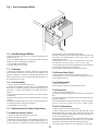
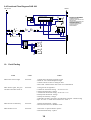
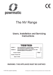
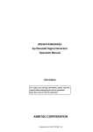
CE
The PAG Range
Installation and Servicing
Instructions
WARNING: THIS APPLIANCE MUST BE EARTHED
£2.50 When supplied separately.
PGUH Range Issue 2
CONTENTS
Section
Title
Page
1.
2.
3.
4.
5.
6.
7.
8.
9.
10.
11.
Introduction
Technical Data
General Requirements
Installation
Air Distribution System
Commissioning & Testing
Servicing
Connections to Powrmatic
External Controls
Electrical Details
Fault Finding
Short List of Parts
Tables
Title
1a.
1b.
2a.
2b.
3.
4.
Dimensions NCE-AG (S.I. Units)
Dimensions NCE-AG (Imperial Units)
Specifications (S.I. Units)
Specifications (Imperial Units)
Burner Pressures - Natural Gas
Group H - G20
Electrical Loadings
Figure
Title
1.
2.
3.
4.
5.
6.
7.
Pilot Flame Adjustment
SIT 820 Nova (PAG 60 - 100)
Honeywell V4605C (PAG 200)
Burner General Arrangement PAG 60 - 100
Cross Lighting Strip Assembly PAG 200
PAG 200 Electrode Settings
Heat Exchanger Baffles
2
3
4
6
7
7
9
12
12
14
15
Page
3
3
4
4
4
4
Page
1
7
8
8
9
10
10
11
1. INTRODUCTION
The Powrmatic PAG range of gas fired open flue, fanned
circulation air heaters cover a heat output range of 17.6 kW
(60000 Btu/h) to 58.6 kW (200000 Btu/h) and are intended
primarily for heating commercial or industry premises. They are
certified for use on Natural Gas, Group H - G20.
The heaters are for floor mounting only and are available in UF
and UD variants. (U - Upright; F - Freeblowing; D - Ducted).
PAG heaters have a centrifugal fan assembly fitted upstream of
the combustion chamber / heat exchanger assembly to circulate
the air being heated.
Heaters are fitted as standard with bar type atmospheric gas
burners. PAG 60 - 100 heaters use a permanent pilot together with
a multifunctional gas control whereas the PAG 200 has fully
automatic ignition.
Options include Deep V filters, proportional air dampers and
inlet and outlet duct spigots.
Each air heater must be connected to a open flue system only.
Gas Safety (Installation & Use) Regulations 1994
It is law that all gas appliances are installed, adjusted and, if
necessary, converted by qualified persons* in accordance with
the above regulations. Failure to install appliances correctly can
lead to prosecution. It is in your own interests and that of safety
to ensure that the law is complied with.
* e.g. Corgi Registered
2
2 Technical Data
2.1 Dimensions
F
G
D
H
D
C
F
G
K
C
J
B
A
E
SIDE
VIEW
FRONT
VIEW
L
B
A
FRONT
VIEW
SIDE
VIEW
PAG 80UF SHOWN
E
PAG 80UD SHOWN
F
G
D
H
C
F
G
K
C
J
B
A
FRONT
VIEW
SIDE
VIEW
E
L
B
A
FRONT
VIEW
SIDE
VIEW
PAG 200UF SHOWN
PAG 200UF SHOWN
Table 1a. Dimensions (S.I. Units)
A
PAG 60
PAG 80
PAG 100
B
C
477
682
PAG 200
569
674
D
E
255
1550
1200
285
303
220
F
H
J
K
389
125
150
270
G
110
200
494
L
378
475
599
1125
460
H
J
609
470
575
1100
Table 1b. Dimensions (Imperial Units)
A
PAG 60
PAG 80
PAG 100
PAG 200
B
C
18.7
26.8
22.4
26.5
47.2
D
E
10.0
61.0
11.2
11.9
8.6
F
K
15.3
5.0
6.0
10.6
G
4.3
8.0
19.4
NOTES:
(1) Rear inlet duct spigot - J x L; Top outlet duct spigot - H x K.
3
14.9
18.7
23.6
44.3
L
18.1
24.0
18.5
22.6
43.3
E
Table 2a - Specifications (S.I. Units)
MAXIMU M D U C T
FAN MOTOR
AIR
R ESISTAN C E
VOLU MMOD EL IN PU T
E
Standard L.H .P. Standard L.H .P.
OU TPU T
(N ett)
H IGH FIR E
kw
PAG 60
19.56
PAG 80
PAG 100
m³/s
17.6
0.3991
26.61
23.4
0.4936
32.81
29.3
0.5794
PAG 200 64.88
58.6
1.159
pa
kg
Refer to
Powrmati c
151
Refer to
Powrmati c
0.335
300
115
WEIGH T
kw
Refer to
Powrmati c
72
GAS
C ON N EC TION
SIZE
2 x 0.355
161
R¾
0.550
171
Refer to
Powrmati c
240
Table 2b - Specifications (Imperial Units)
H IGH FIR E
MOD EL IN PU T
OU TPU T
(Gross)
MAXIMU M D U C T
R ESISTAN C E
AIR
VOLU ME
B tu/h
Standard
ft³/m
FAN MOTOR
GAS
C ON N EC TION
L.H .P.
SIZE
L.H .P. Standard
in wg
74154
60000
846
PAG 80
100885
80000
1046
100000
1228
1.2
0.74
2456
Refer to
Powrmati c
Refer to
Powrmati c
PAG 100 124386
PAG 200 245704
Table 3
200000
0.46
mm
P ilot
R ate
marked
Main B urner
P ressure
kW
2.38
2 x 0.45
m³/h
ft³/h
10.0
4.0
2.07
73.1
11.0
4.4
2.81
99.2
11.0
4.4
3.47
122.5
12.0
4.8
6.86
242.3
N/A
Table 4
ph
PAG 200
376
528
Pilot Injector
Front Orifice dia 0.38 mm
Rear Orifice dia 0.355 mm
Larger H orsepower Motor
MOTOR
R .P.M.
P LATE
AMP S
(A)
S TAR T
AMP S
(A)
RUN
AMP S
(A)
1000
2.6
4.2
1.8
PAG 60
PAG 100
354
Electrical Loadings
S tandard
PAG 80
¾"BSP
Gas R ate
in wg
0.154
238
PAG 200
MOD E L
332
Refer to
Powrmati c
0.45
mbar
PAG 60
PAG 100
Refer to
Powrmati c
Burner Pressures - Natural Gas - Group H - G20 - Net CV (Hi) = 34.02MJ/m³
Injectors
Injector S iz e
PAG 80
lb
hp
PAG 60
0.28
WEIGH T
FU S E
R ATIN G
(A)
MOTOR
R .P.M.
1.7
1
2 x 915
2 x 2.6
10.0
4.9
S TAR T
AMP S
(A)
RUN
AMP S
(A)
FU S E
R ATIN G
(A)
Refer to P owrmati c
5
2.4
P LATE
AMP S
(A)
1250
10
5.0
11.0
4.0
10.0
Refer to P owrmati c
British Standards Code of Practice
3. General Requirements
BS 5588 Fire precautions in the design and construction of
buildings.
Part 2 : 1985 Code of Practice for Shops
Part 3 : 1983 Code of Practice for Office Buildings
BS 6230 : 1991 Installation of Gas Fired Forced Convection Air
Heaters for Commercial and Industrial Space Heating.
BS 5440 : Installation of flues and ventilation for gas appliances
of rated input not exceeding 60kW (1st, 2nd and 3rd family
gases).
Part 1 : 1990 Specification for installation of flues
Part 2 : 1989 Specification for installation of ventilation for gas
appliances.
BS 5864 : 1989 Specification for installation in domestic premises
of gas-fired ducted -air heaters of rated input not exceeding
60kW.
3.1 Related Documents
The installation of the air heater(s) must be in accordance with
the rules in force and the relevant requirements of the Gas Safety
Regulations, Building Regulations and the I.E.E. Regulations for
Electrical Installations.
It should be in accordance also with any relevant requirements
of the local gas region, local authority and fire authority and the
relevant recommendations of the following documents.
British Gas Plc Publications
IM/11 : 1989 Flues for Commercial and Industrial Gas Fired
Boilers and Air Heaters
IM/16 : 1988 Guidance notes for the installation of gas pipework,
boosters and compressors in Customer’s premises (excluding
domestic installation of 25mm and below).
4
3.2 Location
be released, preferably into a gully. The condensation pipe from
the flue to the disposal point should be of non-corrodible
material of not less than 22mm (1/2") size.
Facilities should be made for disconnecting the flue pipe(s) from
the air heater(s) for inspection and servicing purposes. Bends
with removable covers should be fitted for inspection and
cleaning purposes where considered appropriate.
The flue should terminate in a freely exposed position and must
be so situated as to prevent the products of combustion entering
any opening in a building in such concentration as to be
prejudicial to health or a nuisance.
An approved terminal must be fitted.
The location chosen for the air heater must permit the provision
of a satisfactory flue system and an adequate air supply. The
location must also provide adequate space for servicing and air
circulation around the air heater.
The heater(s) must not be installed in conditions for which it is
not specifically designed e.g. where the atmospheric is corrosive
or salty and where high wind speeds may affect burner operation,
and they are not suitable for outdoor use.
Where the location of the air heater is such that it might suffer
external mechanical damage e.g. from overhead cranes, fork lift
trucks, it must be suitably protected.
PAG units are designed to operate in a maximum ambient
temperature of 25 °C.
3.5 Air Supply
In buildings having a design air change rate of less than
0.5 /h, and where PAG heaters are to be installed in heated spaces
having a volume less than 4.7 m3 /kW of total rated heat input,
grilles shall be provided at low level as follows:(1)
for heaters of heat input less than 60 kW, the
total minimum free area shall not be less than
4.5 cm2 per kilowatt of rated heat input.
(2)
for heaters of heat input 60 kW or more, the
total minimum free area shall not be less than
270cm2 plus 2.25 cm2 per kilowatt in excess
of 60 kW rated heat input.
3.3 Gas Supply
3.3.1 Service Pipes
The local gas undertaking should be consulted at the installation
planning stage in order to establish the availability of an adequate
supply of gas. An existing service pipe must not be used without
prior consultation with the local gas undertaking.
3.3.2 Meters
A gas meter is connected to the service pipe by the local gas
undertaking or a local gas undertaking contractor. An existing
meter should be checked, preferably by the gas undertaking, to
ensure that the meter is adequate to deal with the total rate of gas
supply required.
Where the air heater(s) is to be installed in a plant room the plant
room housing it must have permanent air vents communicating
directly with the outside air, at high level and at low level. Where
communication with the outside air is possible only by means
of high level air vents, ducting down to floor level for the lower
vents should be used.
All air vents should have negligible resistance and must not be
sited in any position where they are likely to be easily blocked
or flooded or in any position adjacent to an extraction system
which is carrying flammable vapour.
Grilles or louvres should be so designed that high velocity air
streams do not occur within the plant room.
3.3.3. Installation Pipes
Installation pipes should be fitted in accordance with
IM/16:1988. Pipework from the meter to the air heater must be of
adequate size. Do not use pipes of a smaller size than the inlet
gas connection of the heater. The complete installation must be
tested for soundness as described in the above Code. The
complete installation must be tested for soundness as described
in BS 6230.
3.3.4. Boosted Supplies
The basic minimum effective area requirements of the air vents
are as follows:
(a)
Low Level (inlet)
(1)
for heaters of total rated heat input less than 60 kW:
9 cm2 per kilowatt of rated heat input
(2)
for heaters of total rated heat input 60 kW or more:
540 cm 2 plus 4.5 cm2 per kilowatt in excess of
60 kW total rated input.
(b)
High Level (outlet)
(1)
for heaters of total rated heat input less than 60 kW:
4.5 cm 2 per kilowatt of rated heat input;
(2)
for heaters of total rated heat input 60 kW or more:
270 cm2 plus 2.25 cm2 per kilowatt in excess of
60kW total rated input.
Where it is necessary to employ a gas pressure booster the
controls must include a low pressure cut off switch at the booster
inlet. The local gas undertaking must be consulted before a gas
pressure booster is fitted. The maximum inlet pressure is 60mb.
3.4 Flue System
Detailed recommendations for fluing are given in BS 5440, Part
1 (Flues) and IM/11.
The air heater must be connected to an open flue system. The
cross sectional area of the flue serving the appliance must be not
less than the area of the flue outlet of the draught diverter flue
socket.
Materials used for the flue system should be mechanically
robust, resistant to internal and external corrosion,
noncombustible and durable under the conditions to which they
are likely to be subjected.
Prevention of condensation within the flue should be an important
factor in the design of the flue system. In order to minimise
condensation the use of double walled flue pipe or insulation is
recommended. If double walled flue pipe is used it should be of
an acceptable type.
Where condensation in the flue is unavoidable provision should
be made for condensation to flow freely to a point at which it can
3.6 Air Distribution System
The following notes are of particular importance.
For free-blowing units it must be taken into account that the
buoyancy of the heated air leaving the heater and air patterns
within the space being heated will modify the air throw pattern
achieved. In buildings having a low heat loss where single units
are required to cover a large floor area and in buildings with high
roof or ceiling heights Calecon thermal economiser units should
be fitted to ensure even heat distribution and minimise
5
cellulose spraying is carried out, in wood working departments etc.
PAG heaters must not be installed in areas subjected to negative
pressures due to extract systems.
The following minimum clearances for installation and servicing
must be observed.
To the front
The depth of the heater
To the rear
0.5m (1.6ft)
To at least one side
1.0m (3.3ft)
Above the heater
1.00m (3.3ft)
stratification respectively. Care should be taken to avoid
impeding the air throw with racking, partitions, plant or machinery
etc.
For ducted units all delivery and return air ducts, including air
filters, jointing and any insulation or lining must be constructed
entirely of materials which will not contribute to a fire, are of
adequate strength and dimensionally stable for the maximum
internal and external temperatures to which they are to be
exposed during commissioning and normal operation. In the
selection of materials account must be taken of the working
environment and the air temperatures which will result when the
overheat limit thermostat is being commissioned. Where interjoist spaces are used as duct routes they should be suitably lined
with a fire-resisting material.
A full and unobstructed return air path to the air heater(s) must
be provided.
If the air heater(s) is installed in a plant room the return air
intake(s) and the warm air outlet(s) from the heater(s) must be
fully ducted, in to and out of the plant room to avoid interference
with the operation of the burner and flue by the air circulation
fan.
The openings in the structure of the plant room through which
the ducting passes must be fire stopped.
Care must be taken to ensure that return-air intakes are kept clear
of sources of smells and fumes, and in special circumstances
where there is any possibility of pollution of the air by dust,
shavings etc., precautions must be taken by carefully positioning
return air intakes and by the provision of screens to prevent
contamination.
In addition, where there is a risk of combustible material being
placed close to the warm air outlets, suitable barrier rails should
be provided to prevent any combustible material being within
900mm (3ft) of the outlets.
Any combustible material adjacent to the air heater and the flue
system must be so placed or shielded as to ensure that its
temperature does not exceed 65 °C (150 °F)
IMPORTANT:
1.
No air heater shall be installed where there is a foreseeable
risk of flammable particles, gases vapours or corrosion inducing
gases or vapours being drawn into either the heated air stream
or the air for combustion. In certain situations where only
airborne particles are present it may suffice to fit filters on the air
inlet ducts of the heater. Advice in these instances may be
obtained from Powrmatic Ltd.
4.2 Fitting the Air Heater
The heaters must be installed on a level noncombustible surface.
If noise levels are of particular importance the heater should be
insulated from the structure of the building by installing it on
suitable anti-vibration mountings. In all such cases it is essential
that all gas, duct, electrical and flue connections to the heater are
made with flexible connections to maintain continuity of
connection. In the case of the flue connection single wall
stainless steel flue is deemed to flex sufficiently to meet the
requirements.
4.3 Connection of Air Heater(s) to Flue
System
3.7 Electrical Supply
The draught diverter is integral with each heater. The flue system
connects directly on to the draught diverter and must have a
minimum length of 2.0m. For flue sizes refer to Tables 1a and 1b
Page 3 . Horizontal runs of flue are not permitted. If necessary
a single offset using two 45° bends can be included to avoid
obstructions.
Wiring external to the air heater must be installed in accordance
with the I.E.E. Regulations for Electrical Installations and any
local regulations which apply. Wiring should be completed in
flexible conduit.
PAG heaters are supplied by 230V - 1ph, 50Hz. The method of
connection to the main electricity supply must facilitate the
complete electrical isolation of the air heater(s) and the supply
should serve only the air heater(s).
The isolator must have a contact separation of at least 3mm in
all poles. The method of connection should be provided adjacent
to the air heater(s) in a readily accessible position.
See the accompanying wiring diagram for the heater electrical
connections
4.4 Condensate Drainage
The design of the flue system should minimise the formation of
condensation, however when this is envisaged to be a problem
provision should be made for condensation to flow to a joint
where it can be drained, preferably into a gully.
4.5 Gas Connection
A servicing valve and downstream union must be fitted at the
inlet to the air heater gas controls assembly to facilitate servicing.
The gas supply to the air heater must be completed in solid
pipework and be adequately supported.
WARNING: When completing the final gas connection to the
heater do not place undue strain on the gas pipework of the
heater.
4. Installation of Air Heater(s)
4.1 General
Before installation, check that the local distribution conditions,
nature of gas and pressure, and adjustment of the appliance are
compatible.
4.6 Electrical Connections
The air heater must be installed in accordance with the rules in
force and the relevant requirements of any fire regulations or
insurance company’s requirements appertaining to the area in
which the heater is located, particularly where special risks are
involved such as areas where petrol vehicles are housed, where
All units are fully pre-wired and only require final connections
for the incoming mains supply and completion of the control
circuit (230V) via a room thermostat, time clock etc. The electrical
supply must be run to a point adjacent to the heater and be
suitably terminated to provide an isolation point that will prevent
6
6.3 Air Distribution System
remote activation of the unit during servicing. The heater
electrical panel is located behind the lower front panel and cable
entry points are provided in the adjacent heater framework.
Reference must be made to Table 4 (Page 4) to ascertain the
electrical loading of the air heater(s) being installed so that
cables of adequate cross-sectional area to safely carry that load
are used for the electrical installation. The length of the
conductors between the cord anchorage and the terminals must
be such that the current carrying conductors become taut before
the earth conductor if the cable or cord slips out of the cord
anchorage. All external controls must be of an approved type.
The system should be checked to ensure that the installation
work has been carried out in accordance with the design
requirements.
Particular attention should be given to the correct arrangement
of delivery ducts and registers, return air ducts and grills and
general adequacy of return air paths.
For PAG ###UD heaters ensure that the total duct system
resistance does not exceed the available air pressure of the
equipment supplied refer to Table 2a & 2b (Page4). If the duct
system resistance is less than the available air pressure of the
equipment supplied additional resistance must be introduced
e.g. by adjustment of duct outlet nozzles and balancing of the
duct system.
5. Air Distribution System
5.1 General
6.4 Checks before lighting the Air Heater
PAG ###UD models are designed for use with duct work to more
precisely define the point of air delivery, and /or provide ducted
return air or ducted fresh air inlet. All ducting must be
independently supported of the air heater. Joints and seams of
supply ducts and fittings must be securely fastened and made
airtight.
The following preliminary checks should be made before lighting the heater(s)
a) Ensure that the ELECTRICAL supply to the heater is switched
OFF.
b) Check that all warm air delivery outlets are open.
c) Check that the thermostat is set at MAX.
d) Check that the clock control is set to an ON period.
e) Check that any other controls are calling for heat.
f) Ensure that the Summer/Winter switch is in the Winter
position.
g) Check that the overheat reset(s) has not operated.
5.2 Noise Reduction
If deemed necessary consideration should be given to mounting
the heater on resilient pads, or equivalent, to minimise transfer
of noise and vibration to the structure of the building.
It is recommended that ducting should be connected to the
heater spigots via an airtight flexible coupling of noncombustible
material. Before fitting coupling it must be ensured that a
maximum clearance of 13mm (1/2") will be maintained between
the ends of the ducting and the heater spigots.
If required sound attenuators may be fitted in inlet and outlet
ducts to reduce airborne fan noise. Materials used in outlet
sound attenuators must be capable of withstanding 100 °C air
temperature without any deterioration.
6.5 Lighting the Air Heater
IMPORTANT:
The internal pipework of the appliance has been tested for
soundness before leaving the factory. With the main burners
alight test round the gas inlet connection using a leak detection
fluid.
6.5.1 PAG 60 - 100
NOTES:
- When attempting to light the pilot at any time ensure that the
mains electricity supply is switched off.
- On initial lighting of the heater, it may take some time to purge
the internal pipework of air.
5.3 Room Thermostat Siting
The room thermostat should be fitted at a point which will be
generally representative of the heated area as far as temperature
is concerned. Draughty areas, areas subjected to direct heat e.g.
from the sun, and areas where the air movement is relatively
stagnant e.g. in recesses, are all positions to be avoided for siting
the thermostat.
The thermostat should be mounted about 1.5m (5ft) from the
floor.
Any room thermostat, frost thermostat, time clock etc. must be
suitable for switching 230V, 5A and must be of the 'snap action'
type to minimise contact bounce.
1. Remove the middle front panel.
2. Press the knob of the multifunctional
control (Fig.3a - 1) and rotate to Pilot.
3. Light the pilot flame by pressing the piezo unit button, located
on the heater frame at the right hand side, several times, keeping
the multifunctional control knob depressed. The pilot flame
may be viewed through the sight glass on the front of the unit.
4. Ensure that the pilot flame fully envelopes 9-12mm of the
thermocouple tip (See Fig. 1) and, if necessary adjust the pilot
regulating screw (Fig.2 - 3) .
6. Commissioning & Testing
6.1 Electrical Installation
Checks to ensure electrical safety must be carried out by a
qualified person.
9 - 12 mm
Fig.1
Pilot Flame
Adjustment
6.2 Gas Installation
The whole of the gas installation, including the meter, should be
inspected and tested for soundness and purged in accordance
with the recommendations of IM/16:1988.
5. Once the pilot has been established continue pressing the
7
6.5.2 PAG 200
control knob for approximately 30 seconds and then slowly
release. The pilot should remain alight.
WARNING: Should the pilot be extinguished at any time,
either intentionally or unintentionally, slightly depress the
control knob and rotate clockwise to Off. Wait 3 minutes
before attempting to relight the gas, then repeat steps 3-5
above.
1. Turn on the gas service valve.
2. Switch on the electrical supply at the isolator and the ignition
sequence will commence. After a delay of approximately 30
seconds the ignition spark will be generated and the main gas
valves energized. The burners will then light.
3. If the burners fail to light the control box will go to lockout
and the lockout reset switch at the right hand side of the heater
will be illuminated. To restart the ignition sequence press the
reset switch.
4. SHUT OFF
Switch OFF the electrical supply to the heater or set the clock
control to OFF or set the room thermostat to MIN.
6. Slightly depress the control knob and turn
to On.
7. Switch on the electricity supply at the isolator, and the main
burners will light.
8. SHUT OFF
To interrupt all gas flow through the
multifunctional control slightly depress the
control knob and rotate clockwise to Off.
6.6 Adjustments
6.6.1 Burner Gas Pressure
This is set for the required heat input before despatch. Pressures
should be checked in the following manner.
CAUTION
The restart interlock device prevents the heater from
re-igniting until the flame supervision device has interrupted
the gas flow. After waiting 3 minutes the heater may be relit by
following the previous instructions.
IMPORTANT:
The internal pipework of the appliance has been tested for
soundness before leaving the factory. After establishing the
pilot(s) and with the main burners alight test round the gas inlet
connection using a leak detection fluid.
1. Set external controls to ensure that the main burner is off.
Connect a pressure gauge to the outlet pressure test point on the
multifunctional control (Fig 2-7) or (Fig 3-7).
2. Set external controls so as to turn on the main burner.
Compare the measured burner gas pressure to that stated in
Section 2.
3. If necessary adjust the burner gas pressure by turning the
4a
Fig. 2 - SIT 820 Nova (PAG 60 - 100)
1.
2.
3.
4.
4a.
5.
6.
7.
8.
4
1
Control Knob.
Pressure Regulator cap screw.
Pilot gas rate adjuster.
Thermocouple connection.
Thermocouple interrupter connections.
Pilot connection.
Inlet pressure test point.
Outlet pressure test point.
Electrical connections for main valve
operator.
2
3
PIL
E
6
4
5
OT
A
7
8
1
3
Fig. 3 - Honeywell V4605C (PAG 200)
1.
2.
3.
4.
5.
6.
7.
Governor adjustment cover screw.
Electrical connections for main valve
operator.
Earth connection.
Safety shut off valve.
Safety shut off valve electrical
connections.
Inlet pressure test point.
Burner / outlet pressure test point.
2
5
6
8
7
and associated controls.
Adjust the automatic controls to those values required by the User.
Finally, advise the user or purchaser that, for continued efficient
and safe operation of the air heater, it is important that servicing
is carried out annually.
In the event that the premises are not yet occupied turn off the
gas and electricity supplies and leave instructional literature
adjacent to gas meter.
regulator screw (Fig 2-2) or (Fig 3-1)anticlockwise to decrease
the pressure, or clockwise to increase the pressure.
4. In addition it is advisable to check the gas rate using the gas
meter dial pointer. Ensure that no other appliances supplied
through the meter are in operation.
5. Turn off the main burner by turning the room thermostat to
MIN or the time clock to OFF and disconnect the pressure gauge
and replace the sealing screw. Turn on the main burner by
resetting the external controls and test for gas soundness
around pressure test joint using a leak detection fluid.
7. Servicing
WARNING: Always switch off and disconnect electricity supply
and close the gas service valve before carrying out any servicing
work or replacement of failed components.
6.6.2 Down Draught Diverter
1. Check that there is no spillage of products of combustion from
the air heater down draught diverter by carrying out a spillage
test, as detailed in BS 5440 Part 1.
7.1 General
Full maintenance should be undertaken not less than once per
year by a qualified engineer. After any servicing work has been
complete or any component replaced the air heater(s) must be
fully commissioned and tested for soundness as described in
Section 6.
6.6.3 Air Heater Controls
6.6.3.1
PAG 60 - 100
1. Check that the flame failure device will shut off the gas to the
main burner within 60 seconds by turning off the gas supply at
the gas service valve. A distinct click will be heard when the
thermocouple current is no longer sufficient to hold in the
magnetic unit.
2. Check that the room thermostat and all automatic controls are
operating satisfactorily.
6.6.3.2
7.2 Main Burner Assembly Removal
7.2.1 PAG 60 - 100
1. Ensure that the gas service valve is turned off and then
unscrew the union nut situated immediately down stream of it.
2. Remove the middle front panel.
3. Remove the inside cover plate (that includes the inner viewing
port) above the burner manifold.
4. Release the inlet pipe flange on the multifunctional control.
5. Disconnect electrical wiring from the multifunctional control.
6. Disconnect the ignition lead from the rear of the piezo igniter.
7. Release the two nuts securing the cross lighting strip support
brackets to the anti flame roll shield (See Fig. 4).
8. Release the cross lighting strip support brackets from the
cross lighting strip assembly, remove brackets and then remove
cross lighting strip assembley from burners.
PAG 200
1. Close the gas service tap and ensure that the gas valve is heard
to close within 1 second and that the lockout reset switch is
illuminated. Open the gas service tap and reset the unit from
lockout.
2. Check that the room thermostat and all automatic controls are
operating satisfactorily.
6.7 Handing over the Air Heater
Hand the Users Instructions to the user or purchaser for retention
and instruct in the efficient and safe operation of the air heater
Fig. 4 Burner General Arrangement PAG 60 - 100
HEAT EXCHANGER
CROSS LIGHTING
STRIP
ASSEMBLY
BURNER BARS
AIR GUIDE / BURNER SUPPORT
PLATES
ANTI FLAME ROLL
SHIELD
MANIFOLD
9
Fig. 5 Cross Lighting Strip PAG 200
Rectification
Electrode
Spark
Electrode
Cross Lighting Strip
securing nut and bolt
Cross Lighting Strip
clamping nuts
7.3 Pilot Burner Assembly Removal
PAG 60 - 100
9. Remove the anti flame roll shield from the manifold.
10. Remove four nuts securing burner manifold onto the heat
exchanger and remove manifold complete with pilot assembly
and multifunctional control.
11. The burner bars can now be disengaged from their rear
location slots and removed.
12. If required the air guide/burner support plates may now be
removed.
13. Reassembly is in reverse order. Ensure the burner bars are
located in the slots provided in the rear of the burner bar
supports and that the cross lighting strip assembly is correctly
located on the burners.
1. Complete steps 1 - 9 of Section 7.2.1.
2. Disconnect the thermocouple and pilot gas tube from the
multifunctional control.
3. Remove the two M5 screws securing the pilot assembly to its
mounting bracket.
4. Inspect pilot burner, thermocouple and electrode, making sure
that they are in a sound and clean condition.
In particular check that:
Ignition electrode is clean, undamaged and straight. Check that
the spark gap is 2.5-3mm. Clean the pilot injector, do not broach
out with wire.
5. Refit the pilot assembly and reassemble the burner in reverse
order. Note that the pilot assembly is mounted on top of the
manifold bracket. Ensure that the thermocouple nut at the
multifunctional control is secure, but not over tightened. Tighten
by hand, then tighten by spanner 1/6th of a turn. The terminal
must be clean to ensure a good electrical connection.
7.2.2 PAG 200
1. Ensure that the gas service valve is turned off and then
unscrew the union nut situated immediately down stream of it.
2. Remove the middle front panel.
3. Remove the inside cover plate (that includes the inner
viewing ports) above the burner manifold.
4. Release the inlet pipe flange on the multifunctional control.
5. Disconnect electrical wiring from the multifunctional control.
6. Release and remove the 3 brackets that attach the cross
lighting strip to the anti flame roll shield. Two of the brackets
also carry the ignition and rectification electrodes (See Fig 5).
8. Release the cross lighting strip fixings i.e. remove the 2 facing
nuts and slacken the 4 nuts underneath the assembly, and then
remove cross lighting strip assembley from burners.
9. Remove the anti flame roll shield from the manifold.
10. Remove four nuts securing burner manifold onto the heat
exchanger and remove manifold complete with multifunctional
control.
11. The burner bars can now be disengaged from their rear
location slots and removed.
12. If required the air guide/burner support plates may now be
removed.
13. Reassembly is in reverse order. Ensure the burner bars are
located in the slots provided in the rear of the burner bar
supports and that the cross lighting strip assembly is correctly
located on the burners.
7.4 Ignition and Rectification Electrodes
PAG 200
1. Remove the lower and middle front panels.
2. Release the fixing for the electrode to be replaced and
disconnect the electrode lead from the control box.
3. Reassemble in reverse order.
Fig. 6 PAG 200 Electrode Settings
3 - 4 mm
Spark Electrode
10
5 - 7 mm
Rectification Electrode
Fig. 7 Heat Exchanger Baffles
7.6 Heat Exchanger Baffles
pilot gas tube from the multifunctional control.
5. Remove four M4 screws from the outlet manifold on the right
hand side of multifunctional control and remove the
multifunctional control.
6. Reassemble in reverse order, ensuring the valve is correctly
orientated (See direction of flow arrows on valve body).
7.If necessary renew the inlet and outlet flange sealing gaskets
to ensure that sound joints are obtained.
8. Recommission the heater as described in section 6.
1. Remove the M5 taptite screws securing down draft diverter
baffle (See Fig 7).
2. Remove the M5 taptite screw securing each heat exchanger
baffle, and remove the baffle by sliding out.
3. Clean baffles with stiff brush.
4. Re-assemble in reverse order.
7.7 Flueways
1. Whilst the main burner assembly, burner bar supports and
heat exchanger baffles are removed from the appliance the
flueways should be cleaned by brushing upwards from the
burner compartment. A mirror and torch should be used to see
that the flueways are clean.
7.9.2 Burner Bars (Fig 3)
1. Remove burner assembly as described in section 7.2
2. Reassemble in reverse order and recommission the heater
as described in section 6.
7.9.3 Pilot Assembly
7.8 Fan Assembly
1. Refer to section 7.3.
2. Recommission the unit as described in section 6.
1. Remove the lower front and rear panels.
2. Inspect the fan blades to see that they are not damaged and
that there is no build up of dust to cause an imbalance. If it is
necessary to remove the assembly for cleaning proceed as
follows:
3. Disconnect the fan motors electrical wires from the heater
terminal strip.
4. Remove the two M8 set screws that lock the fan to the fan
shroud.
5. Withdraw the fan from the unit. To the rear if space permits to
avoid having to remove the electrical panel.
6. Reassemble in reverse order.
7.9.4 Piezo Unit
1. Remove the front middle panel.
2. Disconnect the spark ignition lead from the rear of the Piezo
unit.
3. Unscrew the backnut of the Piezo unit and withdraw the unit
from the side panel.
4. Re-assemble the new unit into the panel, reconnect the spark
ignition lead and replace the front middle panel.
7.9.5 Fan Thermostat
7.9 Replacement of Faulty Components
1. Remove the lower front and top panels.
2. The fan thermostat is located at the right hand side of the
heater behind the front edge of the side panel. Remove the
connections from the rear of the thermostat, and remove the two
screws securing the thermostat.
3. Remove the outlet heads, or first length of ductwork, unclip
the thermostat phial from the bracket set on top of the heat
exchanger and withdraw phial down through the heater.
4. Fit replacement thermostat, reassembling in reverse order.
7.9.1 Multifunctional Control
1. Isolate gas and electrical supply to the unit.
2. Remove middle front panel.
3. Release the inlet pipe flange on the multifunctional control.
4. Disconnect electrical supply from the multifunctional control. For PAG 60 - 100 heaters disconnect thermocouple and
11
7.5.6 Limit Thermostat(s)
8.2 Eurotrol
1. Remove the middle and top front panels.
2. The limit thermostat(s) is located at the right hand side of the
heater behind the front edge of the side panel. Remove the
connections from the rear of the thermostat, and remove the two
screws securing the thermostat.
3. Remove the outlet heads, or first length of ductwork, unclip
the thermostat phial from the bracket set on top of the heat
exchanger and withdraw phial down through the heater. On the
PAG 200 the phial of the upper limit thermostat is at the left hand
side of the unit and the phial of the lower limit thermostat is at
the right hand side.
4. Fit replacement thermostat(s), reassembling in reverse order
ensuring that the electrical connections are correct (see Section 9).
Ensure that the thermostat is set as follows
PAG 60, 200
100 °C
PAG 80, 100
90 °C
PAG
Terminals
8.
connect to
Eurotrol
Terminals
1
2
8
9
CTRL CCT
CTRL CCT
FAN CCT
FAN CCT
Connections to Powrmatic External
Controls
8.1 Powrtrol
connect to
PAG
Terminals
Powrtrol
Terminals
1
2
8
9
1
2
5
6
9.1 Wiring Diagram PAG 60, 80 & 100
MULTIFUNCTIONAL GAS VALVE
FAN CONTROL
CIRCUIT
(SUMMER/WINTER)
WHITE
WHITE
EARTH
NEUTRAL
4
6
5
LIVE
4
5
6
7
8
9
10
11
BROWN
BLUE
GR/YELLOW
WHITE
ORANGE
YELLOW
MAUVE
BLACK
1.5mm2
L
3
N
1
3
2
3
4
5
3
7
8
9
8
9 10 11 12 13 14 15 16
3
2
0.5mm2
6
4
9
CABLES
1 BROWN
2 BLUE
3 GR/YELLOW
LANDIS & GYR
LIMIT STAT
FAN STAT
2
CONTROL
CIRCUIT
MAINS SUPPLY
230V 1ph 50 Hz
LANDIS & GYR
3
2
1
2
1
1
10
9
7
4
5
6
12
L
N
E
M
1
3
1
2
3
1
9.2 Functional Flow Diagram PAG 60, 80 & 100
NEUTRAL
230V 1ph 50 Hz
L
N
MULTIFUNCTIONAL GAS VALVE
o
C
LIMIT STAT
o
C
12
16
2
1
6
15
7
13
ROOM STAT
o
C
8
8
L
9
FAN STAT
M
N
1
E
SUMMER/WINTER SWITCH
10
9.3 Wiring Diagram PAG 200
L&G RAK 21.4/2926 LIMIT THERMOSTAT
L&G RAK 20.7011.1 FAN THERMOSTAT
SUMMER/WINTER SWITCH
HONEYWELL V4605C1029B GAS VALVE
MAIN FAN MOTOR
PEKTRON ASS-0459G03A CONTROL BOX
REMOTE RESET/LOCKOUT SWITCH
P634 IGNITION ELECTRODE
P634 RECTIFICATION ELECTRODE
CONTACTOR (240V COIL)
A
°C
2
1
3
A
°C
2
3
F
1
H
PEKTRON ASS-0459G03A
B
1
°C
2
3
4
5
6
D
FAN CONTROL
CIRCUIT
(SUMMER/WINTER)
2
3
1
7 8
9 10 11 12
J
HONEYWELL V4605
CONTROL
CIRCUIT
G
EARTH
MAINS SUPPLY NEUTRAL
230V 1ph 50 Hz
LIVE
9
A
B
C
D
E
F
G
H
J
K
L
3
3
N
1
2
3
4
5
6
7 8
9 10 11 12 13 14 15 16
3
3
E
3
2
L
1
1
N
10
9
E
M
1
7
CABLES
1 BROWN
2 BLUE
1.5mm2
3 GR/YELLOW
4
5
6
7
8
9
10
11
BROWN
BLUE
GR/YELLOW
WHITE
0.5mm2
ORANGE
YELLOW
MAUVE
BLACK
K
13
14
1
2
3
5
A1
E
L
4
N
6
E
A2
13
M
1
9.4 Functional Flow Diagram PAG 200
230V 1ph 50 Hz
NEUTRAL
L
L
13
G
PEKTRON ASS-0459G03A
1 2 3 4 5 6
F
H
A L&G RAK 21.4/2926 LIMIT THERMOSTAT
B L&G RAK 20.7011.1 FAN THERMOSTAT
C SUMMER/WINTER SWITCH
D HONEYWELL V4605C1029B GAS VALVE
E MAIN FAN MOTOR
F PEKTRON ASS-0459G03A CONTROL BOX
G REMOTE RESET/LOCKOUT SWITCH
H P634 IGNITION ELECTRODE
J P634 RECTIFICATION ELECTRODE
K CONTACTOR (240V COIL)
X ROOM THERMOSTAT
J
7 8 9 10 11 12
D
HONEYWELL V4605
X
12
16
A
°C
A
°C
2
1
°C
6
7
15
B
8
8
9
C
10
13
13
K
L
13
14
1
2
3
4
5
A1
E
L
N
6
E
M
1
A2
E
L
N
E
M
1
10. Fault Finding
Fault
Cause
Action
Main burner will not light
Electrical
1. Check electrical and gas supplies are ON.
2. PAG 60 - 100 - Check that pilot is alight.
3. Check controls are ON or calling for heat.
4. PAG 200 - Check lockout reset switch is not illuminated.
Main burner lights, but goes
out before main fan comes on.
Electrical
1. Unit goes out on high limit a. Check fan thermostat setting - See Section 7.9.5.
b. Faulty fan thermostat - change
c. Check limit thermostat setting - See Section 7.9.5.
d. Faulty limit thermostat - change.
2. Faulty fan assembly - change.
3. (Ducted Units Only) -fan motor out on thermal overload. - Check running
amps. See table 4.- check duct resistance See Table 5.
Main fan runs continuously
Electrical
1. Faulty fan thermostat - change
2. Powrtrol or Eurotrol in 'Summer' mode
Main fan fails to run
Electrical
1. Fan motor or capacitor failed - replace.
2. Fan thermostat faulty - replace.
14
11. Short List of Parts
Refer to Powrmatic Ltd for the details of any parts not listed here.
ITEM
APPLICATION
PART NUMBER
MFC - Honeywell V 4600C 1359B
60 - 100
142400425
MFC - SIT Nova 820 0.820.063
60 - 100
142400439
Pilot Assembly Honeywell Q359A 1058
60 - 100
142403002
Pilot Injector - Honeywell 45.004108-001
60 - 100
142402801
Pilot Compression fitting - Honeywell 45.00 4098-002
60 - 100
142400404
Ignition Electrode Vernitron 60820
ALL
142423100
Thermocouple
60 - 100
142403827
60 - 100
142436010
Burner Bar - Bray AB 17510
ALL
142400212
Injector Carrier
ALL
142401701
Thermostat - Fan - Landis & Gyr Rak 20-7011-1
ALL
142403593
Thermostat - Limit - Landis & Gyr Rak 21-4-2924
60 - 100
142403595
Thermostat - Limit - Landis & Gyr Rak 21-4-2926
200
142403597
Fan Assembly - WDBM 09261-05
60 - 80
140210020
Fan Assembly - WDBM 10361-06
100/200
140210010
Full Sequence Control - Pektron ASS - 0459G01A
200
142400413
Piezo Unit
Honeywell Q309A (24" 1
Vernitron 60072
15
BSI Registered Firm
FM 414
Ind. & Comm. Air Heaters;
Air Moving Equipment;
Flues & Chimneys; Natural
Smoke & Heat Ventilators;
Powered Supply & Extract
HEATING DIVISION
Winterhay Lane
Ilminster, Somerset TA19 9PQ
Tel: 01460 53535 Fax: 01460 52341
Every effort is made to ensure accuracy at time of going to press. However as part of our policy of continual product improvement, we reserve the right to alter specifications without prior notice.