1
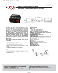
T-TSX3:TEMPLATE
11/25/09
9:43 AM
Page 1
Bulletin T-TSX3
Series TSX3 Digital Refrigeration Temperature Switch
Specifications - Installation and Operating Instructions
3 [76.20]
1-3/8
[35.08]
The Series TSX3 Digital Temperature Switch was designed to control the
compressor, fan, and defrost in refrigeration applications. This generation of
controls has field selectable engineering units and input temperature types in order
to reduce the combination of parts that need to be stocked. A built in real time clock
is used for HACCP logging of temperature alarms caused by temperatures out of
their set limits or loss of power. The Intelligent Defrost parameters manage the
defrost cycle in order to save energy cost. The digital input can be used to remotely
trigger a defrost cycle, monitor cooler door status, or act as an external alarm. For
programming multiple units, the model TS2-K configuration key can be used to
quickly download parameter settings.
INSTALLATION
NOTE: Unit must be mounted away from vibration, impacts, water and corrosive
gases.
• Cut hold in panel 71 x 29 mm (2.80 x 1.14 in).
• Use the supplied gasket or apply silicone around the perimeter of the hole to
prevent leakage.
• Insert unit into hole from the front side of the panel.
• Slide the mounting bracket securely against the panel from the rear of the unit.
• Wiring diagram is displayed on the top of the control.
2-5/8 [66.74]
2-7/16 [61.98]
2-3/4 [69.85]
1-3/64
[26.67]
SPECIFICATIONS
Probe Range:
PTC: -58 to 302°F (-50 to 150°C).
NTC: -58 to 230°F (-50 to 110°C).
Input: PTC (1000Ω @ 25°C) / NTC (10KΩ @ 25°C) Digital Input Contact.
Output: All Models SPST No Relay Resistive Load 16A, Inductive Load 5A, 10
FLA, 60 LRA @ 240 VAC; Dual Output Models also include 8A Resistive, 3A
Inductive SPDT @ 240 VAC; Three Output Models also include 8A Resistive
SPST NO @ 240 VAC, 5A Resistive SPST NO @ 240 VAC.
Horsepower Rating: 1HP @ 240 VAC.
Control Type: On/Off.
Power Requirement: 115 VAC, 230 VAC, 12 VAC/VDC, 24 VAC/DC (±10%)
depending on model.
Power Consumption: 3.6VA (115/230/24 V), 1.5VA (12V).
Accuracy: ±1% FS.
Display: 3 Digits Plus Sign.
Resolution: 0.1°.
Memory Backup: Non-Volatile Memory.
Ambient Temperature: 32 to 131°F (0 to 55°C).
Weight: 2.3 oz (65 g).
Front Protection: IP65.
Agency Approvals: CE, UL.
Wiring
Avoid installing the temperature probe cables and the digital input wires in close
proximity of any power cables. If the length of the probe cables is longer than 100
meters, a recalibration adjustment may be made using the P1 parameter.
LOVE CONTROLS DIVISION
DWYER INSTRUMENTS INC.
P.O. BOX 338 - MICHIGAN CITY, INDIANA 46361, U.S.A.
Phone: 219/879-8000 www.love-controls.com
Fax: 219/872-9057 e-mail:[email protected]
T-TSX3:TEMPLATE
11/25/09
9:43 AM
Page 2
Parameter List
Operation
Compressor/
Set Point
(COn)
Parameter
Set
r0
r1
r2
r4
r6
F0
F1
c0
c1
c2
c3
c4
c5
Defrost (DEF)
d0
d1
d2
d3
d4
d5
d6
d7
d8
d9
d10
d11
d12
d13
d14
d15
d16
d17
HdE
ndE
JdF
P0
P1
P2
P4
P5
P6
A0
A1
A2
A3
Display (Pro)
Alarm
(ALA)
Initial Setup
(Ini)
A4
A5
A6
A7
A8
Hor
nin
E0
H0
H1
H2
H3
H4
H5
H6
H7
H8
H11
dAt
td
Description
Set Point
Differential or Hysteresis
Minimum Value for Set Point
Maximum Value for Set Point
Night Set point Variation
Fan Operation
Fan Stoppage Temperature
Fan Stops when Door Open
Minimum Compressor Stoppage Time
Continuous Cycle Time
On Time of Fault Cycle
Off Time of Fault Cycle
Minimum On Time of Compressor
Minimum Time Between Compressor
Starts
Type of Defrosting
Temperature to Stop Defrosting
Maximum Defrosting Time
First Hour of Day for Defrost
Delay of First Defrost
Display During Defrost
Display Return Limit
Compressor Drip Time
Interval Between Defrosts
Fan works while Defrosting
Fan Drip Time
Minimum Defrosting Time
Fan/Defrosting Control Probe
Intelligent Defrosting
Units to Count Defrost Cycle
Evaporator Set
D2 Maximum Time %.
CiC Time Variation
Next Defrost Time
Next Defrost Time
Defrosts to Skip
Temperature Scale
Ambient Probe Adjustment
Defrosting Probe Adjustment
Decimal Point
Probe to Display
Probe 2 Present
Alarm Differential
Maximum Alarm Temperature
Minimum Alarm Temperature
Time Without Alarm After Continuous
Cycle
Time Without Alarm After Defrost
Time Without Alarm After Opening Door
Time Without Alarm After Power On
Alarm Verification Time
Probe for Alarm
Real Time Hours
Real Time Minutes
Configure Digital Input
Factory Default
Assign Master/Slave
Keypad Protection
Delay Time on Connecting
Serial Communication Address
Keypad Code
Type of Probe
Relay 2 Setup
Relay 3 Setup
HACCP Activated
Real Time Date
Display Refresh Rate
Units
Degrees
Degrees
Degrees
Degrees
Degrees
Range
Degrees
Option
Minutes
H-M
Minutes
Minutes
Minutes
Minutes
Range
R1 to R2
0.1 to 20
-99.9 to R2
R1 to 302
-20.0 to 20.0
On/Off/COn
-99.9 to 302
Yes/No
0 to 240
0.0 to 18
0 to 999
0 to 999
0 to 240
0 to 240
Factory Setting
3.0
1.0
-50.0
150
0.0
COn
28.0
Yes
1
1.0
5
5
0
1
Option
Degrees
Minutes
H-M
Minutes
Option
Minutes
Minutes
H-M
Option
Minutes
Minutes
Option
Option
Option
Degrees
%
Minutes
Hours
Minutes
Number
Option
Degrees
Degrees
Option
Option
Option
Degrees
Degrees
Degrees
H-M
Re/In
-99.9 to 302
0 to 240
00.0 to 18.0
0 to 999
Off/on/-d0 to 240
0 to 240
00.0 to 18.0
Yes/No
0 to 240
0 to 240
sd1/sd2
Off/JuP/CiC
CT/RT
-50.0 to 20.0
0 to 100
0 to 120
Read Only
Read Only
Read Only
F/C
-20.0 to 20.0
-20.0 to 20.0
Yes/No
sd1/sd2
Yes/No
0.1 to 20.0
0.1 to 99.9
0.1 to 99.9
0.0 to 18.0
Re
80.0
30
00.0
0
-d15
0
8.0
No
0
0
sd2
Off
RT
-10.0
50
10
H-M
H-M
H-M
H-M
Option
Hours
Minutes
Option
Range
Option
Option
Seconds
Range
Range
Option
Option
Option
Option
Range
Seconds
0.0 to 18.0
0.0 to 18.0
0.0 to 18.0
0.0 to 18.0
sd1/sd2
0 to 23
00 to 59
Off/A1/In/DEF/Rst
0 to 2
Mst/Slv
Yes/No
0 to 240
0 to 999
0 to 999
PTC/NTC
Lit/FAn/ALA/dEF
Lit/FAn/ALA/dEF
Yes/No
dxx, nxx, yxx
0-999
1.1
1.1
1.1
1.1
sd1
0
00
Def
0
Mst
No
0
0
0
PTC
dEF
Fan
No
d01, n01, y00
0
C
0.0
0.0
Yes
sd1
Yes
4.0
8.0
8.0
1.1
T-TSX3:TEMPLATE
11/25/09
9:43 AM
Page 3
Parameter Description
Compressor / Set Point Menu
SEt Sets the Ambient Temperature set point between r1 and r2
r0
Differential or hysteresis for set point
(For d0 = re)
Ambient temperature ≥ SEt + r0
Output On
Ambient temperature ≤ SEt
Output Off
(For d0 = in)
Ambient temperature ≤ SEt - r0
Output On
Ambient temperature ≥ SEt
Output Off
r1
Minimum value for set point
r2
Maximum value for set point
r4
Set point deviation from Set value during night setting
r6
Fan Relay Operation
On = Fan is always on while temperature < F0
Off = Fan is always off during regulation
CON = Fan is on when compressor is on
F0 Fan turns off when temperature is greater than this value.
Fan turns on when temperature is less than this value + A0
F1 Determines if fan stops when door is open
No = Fan does not stop working when door is open
Yes = Fan stops when door is open
c0 Minimum time compressor must remain off before being restarted
c1 Duration of continuous cold cycle
c2 During probe error, time that output is engaged
c3 During probe error, time that output is disengaged
c4 Minimum time compressor must stay on
c5 Minimum time between compressors starts
Defrost Menu
d0 Type of Defrosting
re = Defrosting without connecting the compressor
in = Defrosting by connecting compressor
d1 Defrosting stops when defrost probe temperature is above this value
d2 Maximum time the control will be in defrost cycle. If set to zero, control will
not defrost
d3 Hour of the day for the first defrost. No defrost cycles will take place before
this time
d4 Upon powering on the control, delay time before first defrost cycle
d5 Display during defrost cycle
Off = Current temperature displayed
On = Temperature at start of defrost cycle displayed until defrost cycle
ends and the temperature is less than or equal to starting temperature or
after the time is set in d6.
d6 Maximum time before the display returns to normal reading after a defrost
cycle
d7 Time after defrost cycle before the compressor can be started
d8 Time between defrost cycles. If set to 0, defrost must be manually actuated
d9 Determines if Fan operates during defrost
d10 Amount of time after defrost before the fan can restart
d11 Minimum duration the control remains in defrost cycle
d12 Determines which temperature probe to use to control the defrost cycle
d13 Selection of Intelligent Defrost Method
off = turns off intelligent defrost
JuP = Skips defrost cycles as necessary
CiC = Adjusts time of defrost cycle as necessary
d14 Units to count the defrost cycle
rt = according to the time the controller was on
ct = according to the time the compressor was on
d15 The time of the defrost cycle will not be counted if the evaporator
temperature is above this value
d16 Sets the normal defrost time as a percentage of d2.
d17 Value that d8 will be incremented or decremented during Intelligent defrost
when d13 = CiC
Hde Hours until next defrost cycle
nde Minutes until next defrost cycle
JdF Displays the adjustments to the defrost cycle during intelligent defrost
When d13 = JuP, displays number of defrost cycles to skip
When d13 = CiC, displays increments of d8.
Display Menu
P0 Selection of Engineering Unit (F or C)
P1 Ambient Probe Calibration Adjustment
P2 Defrosting Probe Calibration Adjustment
P4 Decimal Point Present
P5 Probe to display
P6 Probe 2 Present
Alarm Menu
A0 Alarm Differential or Hysteresis
A1 High Alarm Set Point (Deviation Value)
On when temperature reaches Set + A1 and off at Set + A1 - A0
A2 Low Alarm Set Point (Deviation Value)
On when temperature reaches Set - A2 and off as Set - A2 + A0
A3 Time of Alarm Inhibit after Continuous Cool Cycle
A4 Time of Alarm Inhibit after Continuous Defrost Cycle
A6 Time of Alarm Inhibit after Power Up
A7 Time since Alarm Initiated until Validated
A8 Probe to be used for Alarm Settings
Initial Setup Menu
Hor Real Time Hours
nin Real Time Minutes
E0 Assignment of Digital Input
Off = Digital Input disabled
A1 = External alarm condition when short circuited
In = Door open if short circuited
DEF = Defrost Cycle initiated when shirt circuited
Ndf = Defrost Cycle will be bypassed when shirt circuited
RSt = Night Set Points used when short circuited
H0 Restore Factory Configuration
H1 Assign Master/Slave for Defrost Cycles
Mst = Sends signal through digital input to initiate slave controls to start
defrost
Slv = Performs defrost when receives defrost signal through digital input
(E0 = DEF when using master/slave operation)
H2 Keypad Password Protected
Yes = code is necessary to start/stop defrost or continuous cold cycle.
One minute after entering the code, keypad is locked again
No = Keypad not protected
H3 Compressor delay time upon power up
H4 Address for serial communications (Need Model TS485 communication
module)
H5 Input code to Parameters (factory set at 0)
H6 Input Probe Types: PTC or NTC
H7 Assignment for Relay 2
Lit = Light
Fan = Fan
ALA = Alarm
dEF = Defrost
H8 Assignment for Relay 3 (only available on 3 output models)
Lit = Light
Fan = Fan
ALA = Alarm
dEF = Defrost
H11 HACCP Alarm recording enabled or disabled
dAt Real Time Date can be programmed by holding the set key for 3 seconds.
Then, use arrows to select day. Press set to store day; use arrows to
access month and year
td
The display refreshes at 1 degree if actual temperature is greater than 1
degree higher td seconds before during defrost and open door conditions
Front Panel Operation
Set Point Setup
• Press the Set key once and SEt will be displayed.
• Press Set key again and set point value will be shown.
• Uses the Up and Down arrows to adjust set point.
• Press the Set key to save the new set point.
• Press Set and Down arrow at same time to exit.
Time Setup
• Press the Set Key once and SEt will be displayed.
• Use the Up and Down arrow until Hor is displayed for adjusting the hours.
• Press the Set key to view the current value.
• Use the Up and Down arrow to adjust to current time.
• Press the Set key for 8 seconds to save the new time (PrO will flash on display
once the value is saved).
• Press the Set key to return to the previous menu.
• Use the Up and Down arrow until nin is displayed for adjusting the minutes.
• Repeat steps 3 through 6.
• Press the Set and Down arrow at the same time to exit.
T-TSX3:TEMPLATE
11/25/09
9:44 AM
Page 4
Parameter Programming
The parameters are organized into 6 programming menus (COn, dEF, PrO, ALA,
HAC, and Ini) (HAC is only accessible when H11 = yes).
• Press the Set key for 8 seconds until 0 is displayed.
• Use the Up and Down arrows to reach the assigned security code
(factory setting for this code is 0).
• Press the Set key to accept the code.
• Use the Up and Down Arrows to select programming menu to enter.
• Press the Set key to reach the parameters under each programming
menu.
• Use the Up and Down Arrows to scroll through the parameters.
• Press the Set key to view the value of the parameters.
• Use the Up and Down Arrows to change the values of the parameters.
• Press the Set key to save the changes.
• Press the Set and Down Arrow to go back to the programming menu selection.
• Press the Set and Down Arrow a second time to exit.
Date Setup
• Access the Data Parameter (dAt) in the Initial Setup Menu.
• Press the Set key once to display the day (dXX).
• Press and hold the Set button for 8 seconds will cause the digits to flash and
allow the value to be changed.
• Use the Up or Down arrow to adjust the value for the day.
• Press and hold the Set button for 8 seconds to store the value (Pro will flash
when the value has been stored).
• Use the Up or Down arrows to switch from day (dxx) to month (nxx) or year
(yxx).
• Follow the same steps to adjust the month and year values.
Factory Default
• Go to H0 menu in the Initial Setup Menu.
• Adjust value to 1 for two output models or 2 for three output models.
• Press the Set key for 8 seconds.
• Press the Set key and Down Arrow simultaneously to exit menu.
Manual Default
Press the
key for 8 seconds to activate/deactivate defrost cycle.
Continuous Cold Cycle
Press the Down key for 8 seconds to activate or deactivate a continuous cold cycle.
(CON will flash upon starting cycle and COF will flash upon completion of cold
cycle).
Resetting Keypad Security Code
Press the Set key during power up will reset the security code to 0.
Alarm Validation
Pressing the Down Arrow and the Set Key simultaneously will acknowledge an
alarm condition. The Alarm indicator and the buzzer will turn off after
acknowledging the alarm condition.
On/Off Lights
If one of the relays is set up to control a light, pressing the
will turn on or off the light.
button for 3 seconds
LED Indicators
Indicates that the Compressor is engaged. It will blink when there is a
call for the compressor to turn on during minimum compressor stoppage.
Indicates defrost cycle is active.
Indicates that the Fan in engaged.
Indicates an error or Alarm or error condition.
HACCP Indicates that a HACCP event is being recorded.
Display Messages
In normal operation the probe temperature will be displayed. The display blinks
when waiting for a parameter to be saved or when there is an error saving a
parameter to memory. The following messages can also appear:
Err
ERP1, ERP2
Eri
ALH
ALL
Memory Reading Error
Probe Error (check wiring or replace probe)
Internal Parameter Error (factory default programming)
High Temperature Alarm
Low Temperature Alarm
©Copyright 2009 Dwyer Instruments, Inc.
LOVE CONTROLS DIVISION
DWYER INSTRUMENTS INC.
P.O. BOX 338 - MICHIGAN CITY, INDIANA 46361, U.S.A.
ALE
AEH
AEL
ooo
--DON
DOF
CON
COF
-d-
External Alarm Condition
High Temperature and External Alarm
Low Temperature and External Alarm
Open Probe Error
Short Circuited Probe Error
Defrosting Activated
Defrosting Finished
Continuous Cold Cycle Activated
Continuous Cold Cycle Finished
Defrosting Cycle
During Probe error, the compressor will be cycled according to parameters c2 and
c3. Manual defrosting and manual continuous cold cycle operations can be
activated.
During memory error, the compressor will be cycled 5 minutes on and 5 minutes
off. Manual defrosting and manual continuous cold cycle operations can not be
activated.
HACCP
If this option is activated, the digital temperature switch can register up to 5 alarms
which could be high, low, or blackout. These alarms can be seen in the menu
registry of alarms (HAC).
This first value that appears is the number of registered alarms. Afterwards, for
each alarm (if any have occurred), the value of the temperature and time the alarm
occurred will be displayed. Once the alarm returns to normal state, the temperature
will be recorded along with the amount of time it took to return to this temperature
will be displayed.
When the elapsed time is shown, it will appear as xxd for the number of days.
Pressing the Up arrow will display xxH for the number of hours, followed by xxn for
the number of minutes. Pressing the Up and Down Arrows together for 2 seconds
will delete the current record being displayed. If the Up and Down arrows are
pressed for 2 seconds while in the HAC menu, all of the records will be erased.
Defrosting Cycles
The amount time between defrost can be based off the total time that the
instrument is on or it can be limited to the amount of time the compressor is
running. The first defrost will be performed at the hour of the day set with d3 and
the following cycles will occur in intervals of d8 after the initial defrost.
Intelligent Defrost
By turning on the intelligent defrost, the time between defrost will vary. This time is
only counted if the evaporator temperature is below the value of d15.
Selecting d13 = JuP, some of the defrosts may be skipped. After a defrost, the next
defrost(s) will be skipped based on the value of JdF. JdF is initially 0 and
increments if a defrost ends before a time d16*d2, otherwise it is decremented until
the value is 0. Maximum value for JdF is 3. After JdF = 3, if the next defrost ends
before d16*d2, JdF will be set to 1. Otherwise, JdF will be set to 0.
Selecting d13 - CiC, the defrosting cycle may vary. If a defrost ends before d16*d2,
then the time between defrosts is incremented d17 minutes, otherwise it is
decremented d17 minutes. The initial and minimum value for the time between
defrost is set by parameter d8. The number of time that the time between defrost
has been incremented can be viewed in parameter JdF.
Communication Connector
The communication connector can be used with the TS2-K to read or write the
parameter configuration to the Series TSX3. The connector can also be used with
a TS485 module to communicate with a computer or other device.
MAINTENANCE
After final installation of the Series TSX3 Digital Temperature Switch, no routine
maintenance is required. Clean the surface of the display controller with a soft and
damp cloth. Never use abrasive detergents, petrol, alcohol or solvents. Upon final
installation of the TSX3 Temperature Digital Controller, no routine maintenance is
required. A periodic check of the system calibration is recommended. The Series
TSX3 is not field serviceable and should be returned if repair is needed (field repair
should not be attempted and may void warranty). Be sure to include a brief
description of the problem plus any relevant application notes. Contact customer
service to receive a return goods authorization number before shipping.
Printed in U.S.A. 11/09
FR# R7-443733-00
Phone: 219/879-8000 www.love-controls.com
Fax: 219/872-9057 e-mail:[email protected]