1
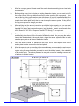
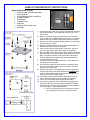
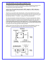
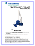
AQUATRAM TM LT POOL LIFT USER MANUAL WARNING IMPORTANT SAFETY INSTRUCTIONS 1. WARNING - TO REDUCE RISK OF INJURY, DO NOT PERMIT CHILDREN TO PLAY ON THIS PRODUCT. 2. WARNING - DO NOT PERMIT CHILDREN TO OPERATE OR USE THIS PRODUCT. 3. SAVE A COPY OF THESE INSTRUCTIONS. © 2011 Pentair Water Pool and Spa, Inc. All rights reserved 1620 Hawkins Ave., Sanford, NC 27330 • (919) 566-8000 10951 West Los Angeles Ave., Moorpark, CA 93021 • (805) 553-5000 AquaTRAM™ and Pentair Water Commercial Pool and Spa are trademarks and/or registered trademarks of Pentair Water Pool and Spa, Inc. and/or its affiliated companies in the United States and/or other countries. Unless noted, names and brands of others that may be used in this document are not used to indicate an affiliation or endorsement between the proprietors of these names and brands and Pentair Water Pool and Spa, Inc. Those names and brands may be the trademarks or registered trademarks of those parties or others. P/N 11239 Rev A - 04/18/11 AQUATRAMTM LT POOL LIFT 300 LB. [136 kg] MAXIMUM CAPACITY MANDATORY – LEAVE THIS MANUAL WITH LIFT OWNER - READ CAREFULLYCheck entire box and inside all packing materials for parts. Before beginning assembly, read the instructions and identify parts using the figures and parts listed in this document. It is critical that all parts be carefully inspected by the installer prior to installation to ensure that no damage occurred in transit and that a damaged part is not used. If any damage occurred in transit, Pentair Water Commercial Pool and Aquatics (“Pentair”) must be notified within three days of receipt of unit. Proper installation cannot be overstressed, as an improper installation voids Pentair’s warranty and may affect the safety of the user. WARNING IMPORTANT SAFETY INSTRUCTIONS 1. READ AND FOLLOW ALL INSTRUCTIONS. LIFT SAFETY CAN ONLY BE ENSURED IF THE LIFT IS INSTALLED AND OPERATED PROPERLY – ACCORDING TO THESE INSTRUCTIONS. 2. WARNING- TO REDUCE RISK OF INJURY, DO NOT PERMIT CHILDREN TO USE OR OPERATE THIS PRODUCT. 3. WARNING- DO NOT PERMIT CHILDREN TO PLAY ON THIS PRODUCT. 4. WARNING- NEVER APPLY DIRECT WATER PRESSURE TO ELECTRONIC COMPONENTS. 5. DO NOT USE THE AQUATRAMTM LT LIFT FOR WATER-DRAFTS OVER 9” (DECK TO WATERLINE). 6. NEVER OPERATE THIS LIFT UNDER LOAD WITH NO WATER (DRY POOL). 7. SAVE A COPY OF THESE INSTRUCTIONS. WARNING MAKE SURE THE AREA AROUND THE LIFT IS CLEAR BEFORE OPERATING. NEVER OPERATE THE LIFT WITH ANY PERSON WITHIN THE OPERATING RANGE OF THE LIFT, INCLUDING ON THE DECK OR IN THE WATER. NEVER MOVE THE LIFT DOWN WHILE OVER THE DECK. IF THE LIFT COMES INTO CONTACT WITH THE DECK OR A WALL, RELEASE THE BUTTON IMMEDIATELY OR PRESS THE EMERGENCY STOP BUTTON. DO NOT ALLOW CHILDREN TO OPERATE THE LIFT WITHOUT SUPERVISION. CHECK ALL NUTS AND BOLTS FOR TIGHTNESS AND FOR WORN PARTS BEFORE EACH USE. AquaTRAMTM LT Technical Support Contact Technical Support at: Sanford, North Carolina (8 A.M. to 5 P.M.) Phone: (800) 831-7133 Fax: (919) 566-8920 Web sites: visit www.pentaircommercial.com 2 AQUATRAMTM LT POOL LIFT TABLE OF CONTENTS PAGE DESCRIPTION 5 PACKING LIST 6 SITE AND POOL DECK REQUIREMENTS 7-8 CORE-DRILL RETROFIT INSTRUCTIONS 9 SAW-CUT RETROFIT INSTRUCTIONS 10 NEW-CONSTRUCTION INSTRUCTIONS 11 AQUATRAMTM LT LIFT ASSEMBLY INSTRUCTIONS 12 24V BATTERY OP & INSTALL INSTRUCTIONS 13 BATTERY MAINTENANCE 14 AQUATRAMTM LT LIFT OPERATING INSTRUCTIONS 15-16 SAFETY & CARE FOR YOUR LIFT 17-19 TROUBLESHOOTING GUIDE 20 AQUATRAMTM LT PARTS LIST 21 SEAT ASSEMBLY PARTS LIST 22 OPTIONS 23 WARRANTY 3 THE AQUATRAMTM LT POOL LIFT 1. 2. 3. 4. AQUATRAMTM LT POOL LIFT W/ FOOTREST (P/N 11230) 24V BATTERY (P/N 11211) BATTERY CHARGER W/ MOUNTING PLATE (P/N 11277) SAFETY BELT (P/N 11215) NOTE: The AquaTRAMTM LT pool lift requires a concrete anchor system (P/N 11231). 4 SITE & POOL DECK REQUIREMENTS This lift is designed for commercial or residential use on in ground pools and spas. This lift is not designed to clear a wall or obstacle. The lift should be installed on the pool deck where a straight linear section of the pool wall is at least six (6) feet long. The lift should be installed at a pool depth (pool deck to pool floor) of no less than 42” but not more than 48 inches. If the edge of the pool deck curves the anchor system will need to be anchored differently than what these instructions outline; contact Pentair Water Commercial Pool and Aquatics for assistance in this case. The front anchors of the lift need to be mounted a maximum of 14 inches and no closer than 4 inches from the inside pool wall. If your pool or spa has hand rails or other extensions on the inside of the pool wall, the set back distance must take these into account. Contact Pentair Water Commercial Pool and Aquatics for assistance in these types of applications. In order to properly install this anchor system into an existing pool deck, your pool deck MUST be at least 3 feet long, by three feet wide and 6 inches thick. It must also be reinforced with #4 rebar on 10 inch centers in both directions. There may be instances where your existing pool deck may not be structurally sound enough or does not meet the minimum requirements outlined above for the safe installation of this anchor system. In those circumstances it is recommended that you follow the Saw Cutting Retro-fit Instructions on page 9. If you are installing this lift in a new application where the pool deck has not been poured yet, then go to the New Construction instructions on page 10. FIGURE 1 5 CORE DRILLING RETRO-FIT INSTRUCTIONS Required Materials & Tools: Core drill and 1 ¼” core drill bit Tape Measure Marking Pen suitable for writing on concrete Hammer Cold Chisel Torpedo Level High Strength 2 part construction epoxy* Black electrical tape (Optional) Masking tape *Pentair recommends either Hilti™ Brand HIT HY-150 or Simpson™ brand ET22 Strong Tie or equivalent 1) Locate the anchor plate, four (4) anchor inserts with nuts and mounting hardware. (Sold separatelyP/N 11231 - See picture). 2) Using the larger holes in the anchor plate as a template, mark the four hole locations with a marking pen on the pool deck. Verify that the CENTER LINE of the front anchors are no more than 14 inches from the pools edge. See FIGURE 1, page 6. 3) Using the core drill and the 1 ¼” core drill bit, drill out the four hole locations marked on the pool deck to a depth of about 4 ½”. a. NOTE: You can use black electrical tape on the end of the drill bit as a visual marker to indicate the proper depth that you need to drill to. b. NOTE: Depending on your local grounding requirements, you may need to drill one hole larger than the others so that you can ground at least one of the anchor inserts. In some cases saw cutting a portion of the deck out completely might be required. In this case, follow the “Saw Cutting Retro-Fit Instructions”. 4) Remove the core from the holes using a hammer and chisel. The holes should be completely dry and clear of any debris before installing the anchors into them. 5) Remove the nuts from the threaded anchor inserts and the black protective cover from the end of the anchor insert exposing the internal threads that will accept the mounting hardware. 6) Using the smaller holes in the anchor plate, thread the mounting hardware through the anchor plate holes and into the ends of the four anchor inserts so that the tops of the inserts are flush with the BOTTOM of the plate (see diagram on left). IMPORTANT: Use the enclosed packet of anti seize on the threads of the hardware to prevent the hardware from seizing in the anchor inserts. a. NOTE: It is recommended that you apply tape to the bottom of the anchor plate around the holes so that when and if the two part epoxy oozes out of the holes that it does not secure the anchor plate to the pool deck. 6 7) Allow for a way to ground at least one of the anchor inserts according to your local code requirements. 8) Before putting epoxy into the holes and setting the anchor inserts, you will want to test fit the anchor inserts in the pre-drilled holes first to make sure they line up properly. You can do this by picking up the anchor plate with the four (4) anchor inserts attached to the underside and carefully place them into the four holes drilled in the deck. Using a torpedo level on the plate, verify that you can level up the anchor system. If they do not line up you may have to enlarge your holes. 9) After verifying that the anchor inserts line up with the holes properly and you can level the anchor assembly, remove the anchor assembly and fill each hole in the pool deck at least half full of two part construction epoxy (not included). Pentair recommends either Hilti™ Brand HIT HY-150 or Simpson™ brand ET22 Strong Tie or equivalent. 10) Pick up the anchor assembly with the four (4) anchor inserts attached to the underside and carefully place them into the four holes drilled in the deck. As you place the anchor inserts that are attached to the anchor plate, wiggle the anchor system a little to make sure the epoxy gets on all sides of the anchor inserts. 11) Once the anchor inserts are placed into the holes, use a small torpedo level on the anchor plate to make sure you are level and plumb. 12) Allow the epoxy to set up according to the manufacturers recommendations and remove the hardware and the anchor plate. You can now safely mount the lift to the anchor system using the same hardware you used to mount the anchor inserts to the underside of the anchor plate. The anchor plate can be recycled or used for installing a second set of anchors in another location. 7 SAW-CUTTING RETRO-FIT INSTRUCTIONS Required Materials & Tools: Concrete saw with Diamond blade Tape Measure 4’ long Straight edge or chalk line Sledge Hammer Cold Chisel Torpedo Level Sting line Concrete & Concrete tools #4 Rebar 1) Locate the anchor plate, four (4) anchor inserts with nuts and mounting hardware). (Sold separately from lift, P/N 11231 See picture). 2) Mark out a section of the pool deck that you are removing using a chalk line or straight edge and a marker. You should plan on removing at least a Three foot by three foot section. 3) Using the saw with the diamond blade, make your cuts along the lines that you marked. 4) Using the sledge hammer, break up the concrete within the area that you cut and remove the pieces. 5) After you have removed the portion of the deck, verify that your new deck will be able to be at least 6 inches deep. 6) Remove ONE of the nuts from each of the anchor inserts and place the anchor inserts through the larger holes in the anchor plate. Thread the nut back on the other side of the anchor insert so that the anchor plate is sandwiched between the nuts. (See diagram on left). 7) Install rebar in the open area of the deck. Tie the rebar into the existing deck if possible. 8) Set the anchor system in place making sure that the center line of the front anchor inserts are no more than 14 inches away from the pools edge. 9) Using the string line or a straight edge, make sure the top of each anchor body is level and flush with the FINISHED deck surface. Each anchor body can be adjusted individually by turning the nuts with a large wrench. 10) Ground the anchor system using the grounding lug on the anchor plate according to your local code requirements. 11) Pour your concrete and finish the pool deck surface. 12) Once the concrete has cured, install the lift by aligning the holes in the lifts base with the anchors installed in the deck. Secure the lift to the deck using the stainless steel hardware that comes with it. (See drawing below) a. NOTE: Use Anti Seize on the hardware to prevent the hardware from seizing in the anchor inserts. 8 ANCHOR INSTALLATION: NEW CONSTRUCTION For installations where a new deck is being poured, or where a dedicated pad is being poured just for the pool lift, the concrete must satisfy the requirements outlined on page 6. For convenience here are the requirements again; YOUR POOL DECK MUST BE AT LEAST 3-FEET LONG BY 3-FEET WIDE BY 6INCHES THICK. IT MUST BE REINFORCED WITH #4 REBAR ON 10-INCH CENTERS IN BOTH DIRECTIONS. Obviously you may make the deck larger than this – which is almost always the case when putting in a deck that surrounds the pool. Note that the entire deck does not need to be 6” thick, but that the area around the installed lift, 3’ by 3’, should be 6” thick at a minimum. The rest of the deck may be thinner – 4” is typical – as long as it is 6” thick around the lift. The entire deck should be reinforced with #4 rebar on 10” centers in both directions, which is also common for this type of structure. Our minimum requirement is that the 3’ by 3’ section be reinforced accordingly, but it is good practice to extend the rebar grid over the entire deck. Commonly, the rebar grid is used for grounding/bonding also. Grounding of the lift can usually be accomplished with a length of bare, solid, copper wire, 14 or 16GA, wrapped tightly around a piece of the rebar and then connected to the grounding lug on the anchor plate. Note that this is only effective when the rebar grid itself has been grounded. CHECK YOUR LOCAL ELECTRICAL CODE: GROUNDING REQUIREMENTS FOR POOL EQUIPMENT. ALWAYS GROUND THE UNIT PER LOCAL ELECTRICAL CODES. 9 AQUATRAMTM LT POOL LIFT - ASSEMBLY INSTRUCTIONS 1. Attach seat belt as shown in FIGURE 7. 2. Install the AquaTRAMTM LT pool lift onto the four (4) anchors using 1/2 x 1-1/2” stainless steel hex-head bolts and 1/2" stainless steel flat washers. Make sure all bolts are tight before using the lift. (FIGURE 9) 3. Plug the handset cable into the large handset socket on the bottom of the control box. Be sure you press the cord end firmly into the socket until you are sure it is all of the way into the socket. Failure to fully push the remote cord into the socket may result in faulty or interrupted operation. (FIG. 8) 4. Before installing the battery, put it on the charging unit and let it charge for 24 hours. Make sure the orange “charge” light illuminates when the battery is being charged. 5. Remove the fully-charged battery from the charger and install it on top of the Control Box as shown in FIGURE 9. The battery will line up square with the control box, and will ‘click’ when it locks in place properly. The lift will only operate when the battery is mounted properly. WHEN LIFT IS NOT IN USE STORE THE BATTERY ON THE CHARGER. DO NOT LEAVE THE BATTERY ON THE LIFT WHEN NOT IN USE! 10 24-VOLT BATTERY SYSTEM OPERATING AND INSTALLATION INSTRUCTIONS The AQUATRAMTM LT Pool Lift comes with a 24v sealed rechargeable battery, wall mount charging unit (with mounting bracket), control box, and a waterproof handset controller. The control box is mounted to the AQUATRAMTM LT Pool Lift and has a plug-in socket for both the actuator and the handheld controller. The battery mounts directly above the control box with a quick-release clip. To operate the AQUATRAMTM LT Pool Lift, plug in the handset controller to the control box and push the corresponding button to either lower or raise the unit. The lift should be able to complete approximately 10-20 full cycles before the low battery indicator tone will sound. The low battery tone indicates that there is approximately 20% battery life remaining. At this point, DO NOT ATTEMPT TO OPERATE THE LIFT, remove the battery from the unit and recharge on the wall mounted charging unit. To recharge the battery, simply grip the top of the battery and depress the clip on the back of the battery. This will unclip the battery from the control box bracket and the battery can then be clipped into the wall mount charger. When the charger is plugged in the green ON light will illuminate. When the battery is correctly mounted to the charger, the orange CHARGE light will illuminate. When the battery is fully charged, the CHARGE light will GO OFF and the battery is ready for use. WHEN THE BATTERY IS NOT BEING USED IT SHOULD BE STORED ON THE CHARGER AND NEVER ON THE LIFT. 11 BATTERY MAINTENANCE 1. WHEN LIFT IS NOT IN USE STORE BATTERY ON CHARGER. The battery power unit is a sealed lead acid battery pack. Frequent recharges will prolong the battery life and maintain a high cold amperage capacity. THE BATTERY CAN BE STORED ON THE CHARGER WHEN NOT IN USE. 2. Do NOT expose the battery to freezing temperatures. 3. Do NOT expose the battery to prolonged periods of extreme heat or severe cold temperatures. 4. Do NOT expose the battery to long periods of direct sunlight. Heat will shorten your battery life. Optimum operating temperature is below 68 degrees F (20 degrees C). 5. Never drop or bump the battery pack. This may result in loose or damaged internal connections, and may bend the battery terminals. 6. Keep battery terminals clean and free from dirt and corrosion to ensure good contact. The terminals may be cleaned using a Scotch Brite pad or any similar product. Clean off any corrosion or discoloration on the very top surfaces of the battery contacts and then apply dielectric grease (supplied with lift) as shown in the figure below. 12 AQUATRAMTM LT POOL LIFT OPERATING INSTRUCTIONS: NOTE: CHECK ALL NUTS & BOLTS FOR TIGHTNESS AND FOR WORN PARTS BEFORE EACH USE. NEVER OPERATE THE LIFT WITH THE ARMRESTS FLIPPED UP. LOADING FROM A WHEELCHAIR: The AQUATRAMTM LT Pool Lift should always be in the fully upright position when transferring into the chair. Before transferring, check to make sure the lift is operating by making a short test run: move the chair at least part way in and out of the pool. The armrest on either side will flip up to allow for easier lateral transfers. Transfer into the chair and then lower the flip-up armrest back into its normal position. Secure the adjustable lap belt around the waist so that the belt is snug, but not uncomfortably tight. OPERATING THE AQUATRAMTM LT POOL LIFT: The HANDSET CONTROL is used to raise and lower the lift during operation. To lower the chair into the pool, press and hold the ▼ “MOVE DOWN” button (see diagram to the left). The lift will move “DOWN” towards the water as long as the ▼ “MOVE DOWN” button is pressed. To stop moving, simply release the button. To “MOVE UP” back to the fully upright position, press and hold the ▲ “MOVE UP” button. Again, the lift will move only as long as the button is pressed and held. When you are sufficiently submerged into the water, release the ▼ “MOVE DOWN” button. Now remove the lap belt by grasping the end of the belt that is protruding above the lap belt and tugging gently. To create more room in front of the chair, the footrest may be flipped inwards, under the chair. Exit the chair by sliding straight forward until you are clear of the seat and the footrest. When you are ready to return to the lift, make sure that the chair is lowered (submerged) sufficiently to allow you to easily slide into the chair. Next, resecure the adjustable lap belt snugly around your waist. Raise the chair out of the pool by pressing and holding the ▲ “MOVE UP” button, until the lift is once again fully upright. 13 SAFETY & MAINTENANCE INSTRUCTIONS DO NOT PLAY ON OR AROUND THIS LIFT 1. Check the AquaTRAMTM Series Pool Lifts before each use to assure there are no worn parts and that all hardware is properly tightened. If there are any worn parts, replace them BEFORE using the AquaTRAMTM Series Pool Lifts. You can call our customer service at 1-888-687-3552 to order any parts. 2. Pentair Water Commercial Pool and Aquatics lifts shall be grounded per local codes. 3. At least ONCE A WEEK, the AquaTRAMTM Series Pool Lifts must be cleaned with fresh water. Do not spray the AquaTRAMTM Series Pool Lifts 24v battery unit directly with any pressure. Wipe all surfaces clean with a damp, nonabrasive cloth. When cleaning the AquaTRAMTM Series Pool Lifts, use nonabrasive soap and water. Avoid harsh chemicals and disinfectants. 4. Always read the label instructions on any cleaner carefully before applying it to a surface. 5. The WARNING & INTENDED USE labels on the AquaTRAMTM Series Pool Lifts must be maintained in readable fashion. If they become unreadable or faded, please replace the label immediately. Replacement labels are available from Pentair Water Commercial Pool and Aquatics. 1-800-831-7133. CARE OF YOUR LIFT Routine cleaning is an absolute necessity to ensure the integrity of the lift. Note that the AquaTRAMTM LT Pool Lift should not be stored in a pump room or in a storage room where pool chemicals are kept. Storing the lift near pool chemicals may cause rusting and other damage to occur. Your AquaTRAMTM LT stainless steel lift is powder coated to protect the stainless steel from rusting. Most rusting will occur at weld points, crevices, under gaskets, rivets or bolt heads. The choice of a proper cleaning product is up to the consumer and there are many to choose from. Depending on the type of cleaning and the degree of contamination (rusting), some products are better than others. For routine cleaning the products most recommended are gentle soaps or detergents or dilute mixtures of ammonia. For stubborn spots and stains try using soft scrub with some brisk rubbing. DO NOT USE POOL WATER TO CLEAN USE ONLY FRESH WATER If the lift is used DAILY make sure to wash the lift at the end of the day. Wash the lift off using a mild soap and a soft cloth. Make sure to pay special attention to weld points and crevices. Do not use a bristled brush or steel wool to clean the lift. Check that the lift is working properly and then place the battery on the charger. It is recommended that the battery be charged after every day of use. If the lift is used WEEKLY follow the same steps as above. Also be sure to check all of the contact points (terminals) for damage or corrosion. If you notice corrosion gently clean the terminals. To clean corrosion from the terminals use a Q-tip and some rubbing alcohol. If the corrosion is particularly stubborn try using a 3M scotch brite pad, but be careful not to damage the terminals. Apply dielectric grease to the terminals after cleaning them. This will help to prevent further corrosion. Do not leave the battery on the lift. Always store the battery on the charger whenever the lift is not being used. 14 If the lift is used MONTHLY follow the same steps as above. Also check the nuts and bolts to make sure they are securely fastened (this is always a good idea, no matter how often or infrequently the lift is used). Also make sure to store the battery on the charger and not on the lift. Leaving the battery on the lift for extended periods will significantly shorten the battery’s lifespan. If the lift is being STORED for an extended period of time follow all of the steps above. Check for rusting at all crevice and weld points. If you notice rusting spray some WD-40 on the affected area and take a 3M scotch brite pad and rub briskly. Afterwards be sure to wash and rinse the lift again with soap and water. When storing the lift make sure it is in a dry area and covered. DO NOT STORE in or around pool chemicals. 15 TROUBLESHOOTING GUIDE Before troubleshooting make sure the battery is fully charged. If the lift doesn’t move when the handset button is pressed: When you can’t get the lift to move check the following things: 1. Make sure the battery is fully charged: A. Before charging the battery first make sure the green light on the front of the charger is illuminated (this means that the charger is on). Then check to make sure the silver contact points on the battery and charger are not damaged or corroded, and that they are clean. Then place the battery on the charger and look for the orange charge light to illuminate on the front of the charger. When the orange light goes off the battery is fully charged. B. The top green light will always be illuminated indicating that it has power. When charging the battery the bottom orange light will illuminate, until fully charged. C. When the battery is correctly installed on the charger or control box you should hear a “click” indicating the battery is properly seated on the unit. Also note that when the battery is properly seated there should not be any gaps between the battery and the control box/charger. Not attached properly. Note the white bracket is in front of silver clip, which will not allow for an electrical connection. Properly Attached. Note that the white bracket is behind the silver clip. Not allowing movement. 16 If the battery is fully charged and the lift is not moving then: 2. Check all cords: A. Check that the cords are properly plugged in. Start by unplugging the remote and the actuator cord from the control box. Once these cords are removed check the ends for corrosion or damage. Plug the remote cord back in by lining up the raised tab on the plug to the grooved line on the control box outlet. Note that these cords require some force to plug them in fully. You will know they a correctly inserted when you here a “popping sound”. The cords will be recessed into the outlet. If they are flush with the outside of the outlet they are not plugged in fully and the lift will not function. Make sure you do this for both cords. NOT inserted fully. Fully inserted. If you have checked all the cords and the lift still doesn’t move: 3. Check the contact points: A. After you have fully charged the battery and checked the cords to make sure they are properly plugged in, check to make sure the contact points are not corroded or bent. If the contact points are corroded take some rubbing alcohol and a q-tip and clean off the points. After cleaning the contact points it is recommended to put some dielectric grease on the contact points (terminals) to help ensure good electrical contact and prevent corrosion. Then reinstall the battery on top of the control box. Make sure you hear a “click”, which indicates that the battery is correctly seated. The lift will not work if the battery is not seated correctly. Silver tabs are the contact (terminal) points. 17 If the lift stops moving over the water and is stuck: 4. Then try pushing the emergency button: A. If the lift gets stuck out over the water use a pen or pencil tip and stick it into the emergency button on the front of the control box to retract the lift. Note the lift will not retract if the battery is not fully charged or if the control box is not working. The emergency button only overrides the remote in case it has gone bad. If this does not retract the lift then chances are the remote is fine and you either have a problem with the battery, the control box, or the cords are damaged or not plugged in properly. Use a pen or pencil tip to push in the small black circle located next to the word emergency, on the front of the control box. USING THE “EMERGENCY BUTTON” on the AquaTRAMTM LT Pool Lift Control Box On the front side of the control box is a small recessed button marked “emergency”. Take a pen or pencil or other pointed object and depress the “emergency” button. This will bypass the remote control and send a signal directly to the actuator to raise the seat out of the pool and back to the deck or up position. NOTE: This function will only work if there is sufficient power in the battery, the battery is properly attached to the control box, and the control box must be operating properly. 18 AQUATRAM LT POOL LIFT PARTS LIST 19 SEAT ASSEMBLY: PARTS LIST ITEM # QTY DESCRIPTION 1 1 SEAT BODY 2 2 SEAT ARMREST TUBE 3 2 SEAT ARMREST HANDGRIP 4 2 1/4"-20 x 3" HEX BOLT, S.S. 5 2 1/4" FLAT WASHER, S.S. 6 1 1/4" QUICK RELEASE PIN, S.S. 7 1 LANYARD FOR QRP 8 1 SHEET METAL SCREW, S.S. 20 Options for AquaTRAM™ LT: Adjustable Head Rest (P/N 11205) Includes: • Padded head rest mounted to adjustable bracket with mounting hardware Adjustable Chest Strap (P/N 11206) Includes: • Adjustable hook and loop style chest strap and mounting hardware Pullout Leg Rest (P/N 11208) Includes: • Pullout leg rest (to be factory installed) Cycle Attachment (P/N 11207) Includes: • Pedal attachment and mounting hardware (cannot be used on lifts equipped with Pullout Leg Rest 11208) • 90° up turned hand grips for better support Protective Cover (P/N 11204) Transport Cart (P/N 11232) 21 AquaTram™ LT Swimming Pool Lift TWO (2) YEAR LIMITED WARRANTY A Division of Pentair Water Pool and Spa, Inc. AquaTram™ LT Lift has a Limited TWO-YEAR Warranty on the frames, not including the powder coat finish. Pentair Water Pool and Spa, Inc. (“Pentair”) also warrants to the original end user purchaser that the AquaTram™ LT Lift (“Lift”), when properly installed in accordance with assembly and installation instructions, and properly used and maintained, shall be free from defects in material and workmanship for a period of two (2) years from the date of original purchase, provided that Pentair receives prompt notice in writing of any claim and satisfactory proof thereof. This warranty specifically excludes reimbursement for labor to remove, repair, replace or install the Lift or component part thereof and any return freight charges. These warranties do not cover any damages due to accident, misuse, abuse, negligence or failure to properly maintain any Lift or component part thereof, or normal wear and tear from day to day operations. In the event that any Lift or component part thereof are altered, repaired, or improperly installed or improperly used by anyone without the prior written approval by Pentair, all warranties are void. IMPORTANT: AMOUNT OF WEIGHT PLACED ON LIFT SHALL NOT EXCEED THE RATED LIFT CAPACITY OF 300 POUNDS (136 KG). To initiate a warranty claim, the owner of an AquaTram™ Lift must provide the place of purchase, in writing, with a full description of the Lift, its serial number, the dates of purchase and installation, and the exact nature of the claim. Within thirty (30) days after receipt of a written warranty claim by Pentair, and barring any unforeseen delays, the place of purchase will be notified of Pentair’s decision regarding the claim. If requested by Pentair, any Lift or component part thereof must be returned, freight prepaid, to Pentair’s designated factory location or duly appointed distributor for inspection and/or repair or replacement. Pentair will, at its option, refund the purchase price, or repair or replace the Lift or component part thereof, and deliver the repaired Lift or component part thereof or replacement to the buyer of the Lift, freight prepaid to the destination provided for in the original order. Lift or component part thereof returned to Pentair for which Pentair provides replacement under this limited warranty shall become the property of Pentair. A new warranty period shall NOT be established for the repaired or replaced Lift or component part thereof. Such Lift or component part thereof shall remain under warranty only for the remainder of the original warranty period on the original Lift purchased. This written limited warranty constitutes the final, complete and exclusive statement of warranty terms. No person or organization is authorized to make any other specific or implied warranties or representations on behalf of Pentair. THE WARRANTIES SET FORTH HEREIN ARE IN LIEU OF ALL OTHER WARRANTIES, EXPRESSED OR IMPLIED, WHICH ARE HEREBY DISCLAIMED AND EXCLUDED, INCLUDING WITHOUT LIMITATION ANY WARRANTY OF MERCHANTABILITY OR FITNESS FOR A PARTICULAR PURPOSE OR USE. THE SOLE AND EXCLUSIVE REMEDIES FOR BREACH OF ANY AND ALL WARRANTIES WITH RESPECT TO THE LIFT OR COMPONENT PART THEREOFSHALL BE LIMITED TO REPAIR OR REPLACEMENT AT PENTAIR’S DESIGNATED FACTORY LOCATION, OR DULY APPOINTED DISTRIBUTOR, OR SUCH OTHER PLACE AT PENTAIR’S SOLE OPTION. IN NO EVENT SHALL PENTAIR’S LIABILITY EXCEED THE ENTIRE AMOUNT PAID TO PENTAIR BY THE ORIGINAL PURCHASER FOR THE LIFT OR COMPONENT PART THEREOF. IN NO EVENT SHALL PENTAIR BE LIABLE FOR ANY INCIDENTAL, CONSEQUENTIAL, SPECIAL, INDIRECT, PUNITIVE OR EXEMPLARY DAMAGES OR LOST PROFITS FROM ANY BREACH OF THIS LIMITED WARRANTY OR OTHERWISE. Pentair Water Commercial Pool and Aquatics™, A Division of Pentair Water Pool and Spa, Inc. 1620 Hawkins Ave., Sanford, NC 27330 1351 Route 55, LaGrangeville, NY 12540 22 PENTAIR WATER POOL AND SPA, INC. 1620 Hawkins Ave. Sanford, NC 27330 - 10951 W. Los Angeles Ave. Moorpark, CA 93021 - Phone 800-831-7133 - Fax 800-284-4151 P/N 11239 Rev A 23