1
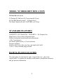
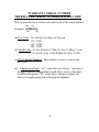
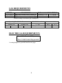
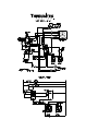
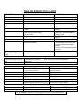
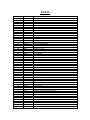
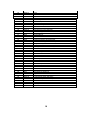
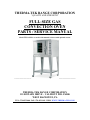
THERMA-TEK RANGE CORPORATION
“QUALITY AND STRENGTH”
FULL-SIZE GAS
CONVECTION OVEN
PARTS / SERVICE MANUAL
Model TFCO-GM-1 covered in this manual is shown with optional casters.
_____________________
________________
THERMA-TEK RANGE CORPORATION
115 ROTARY DRIVE – VALMONT IND. PARK
WEST HAZLETON, PA
TEL: 570-455-3000 FAX: 570-455-9491 WEB: WWW.THERMA-TEK.COM
INTRODUCTION
The Full-Size Gas Convection Oven Parts / Service Manual contains
Installation and Operation Recommendations. It also includes
Troubleshooting and Technical Data such as Orifice Hood Sizing and Gas
Pressure Requirements.
The material presented should be used in conjunction with the Owner’s
Manual, Professional Training, Service Experience, and Industry Standard
Practices.
TABLE OF CONTENTS__________PAGE
Model Number Identification………………………………….3
Full-Size Gas Convection Oven Standard Features...…………3
Rating Plate Location……………………………………….....3
Identifying the Age of Equipment by Warranty Number……..4
Gas and Electrical Requirements.……….,…………………....5
Wiring Diagram………………………………………………..6
Troubleshooting Guide………………………………………...7
Parts – Exploded View and Detail List…………………..8 – 10
Notes………………………………………………………….11
2
MODEL NUMBER IDENTIFICATION
TFCO-GM-1 (N OR L)
T (Therma) F (Full-size) C (Convection) O (Oven)
G (Gas) M (Manual control) – 1 (Single deck)
The Final Character N or L (NATURAL or LP Gas).
STANDARD FEATURES
60,000 BTU’s /Hr. Natural Gas. 54,000 BTU’s / Hr. Propane Gas.
Single door w/ heavy duty refrigerator latch.
Electro-mechanical control snap-action thermostat.
½ Hp 2 speed motor.
Six chrome plated racks w/ 12 rack positions.
Pressure regulator.
Stainless steel front, sides, top, legs, and single deck shelf.
3 wire, 15 amp cord and plug provided.
RATING PLATE LOCATION
The rating plate is located on the right – front of the oven – above the
control panel. It contains the warranty serial number, installation clearances,
and gas pressure information.
3
WARRANTY SERIAL NUMBER
THERMA-TEK SERIAL NUMBER & DATE CODE
Date of manufacture is a date code and is part of the serial number.
(a) (c)
Example: 09J00001A
(b)
(d)
(a)Year Code: Use the last two digits of the year.
07 = 2007
08 = 2008
09 = 2009
(b) Month Code: A=Jan, B=Feb, C=Mar, D=Apr, E=May, F=Jun,
G=Jul, H=Aug, I=Sep J=Oct, K=Nov, L=Dec
(c)5 Digit Serial Number: This number is reset to zero on the
new year.
(d) Engineering Digit: “A” is used for new release. Anytime a
design element is changed that would affect service, this digit
would be changed to “B”. Each time a change is made, the
letter is changed going down through the alphabet.
4
GAS REQUIREMENTS
MODEL
TFCO-GM-1N
TFCO-GM-1L
DESCRIPTION
TOTAL GAS CONSUMPTION
Single deck, manual control, natural gas
60,000 BTU’s / Hr.
17.59 kW
Single deck, manual control, propane gas 54,000 BTU’s / Hr.
15.82 kW
(Double decking ovens doubles gas consumption.)
Operating Manifold Gas Pressure
Natural Gas
5” WC
12.45 mbar
Manifold Connection
Propane Gas
10” WC
24.9 mbar
¾” NPT
¾ “Regulator Provided
ELECTRICAL REQUIREMENTS
120v / 1 PHASE. 6.4 AMPS per oven
________________________________
3 Wire 15 AMP Cord & Plug provided
A wiring diagram is provided on the next page
5
Burner Orifice Drill Size
Nat #
LP #
L 44 R 41
L 55 R 53
6
TROUBLESHOOTING GUIDE
PROBLEM
Oven will not light.
POSSIBLE CAUSE
Gas turned off.
Oven is not plugged in.
Circuit breaker tripped.
Power switch on control panel is off.
SOLUTION
Turn gas valve ON.
Plug in the electrical supply cord.
Reset the breaker.
Turn the power switch to Cook.
Thermostat set lower than temperature in the
oven
Door switch not activating.
Switch is bad.
Solenoid valve not opening.
Set the thermostat to desired
setting.
Check door switch mechanism.
Change switch.
Check for loose wires, if bad
replace.
Adjust gas pressure.
Check ignition cable is attached
securely to igniter and ignition
module.
Check all wires on ignition module
are secure.
Realign igniter until proper
ignition occurs.
Low Gas Pressure
Igniter not sparking.
Igniter sparking and gas
flow present, burner won’t
light
Misalignment of igniter.
Oven Ready light won’t go
off.
Oven has not reached set
temperature
Oven burners did not light.
Fan does not run.
Wait for oven to reach set temperature.
See solutions above.
Oven is not plugged in.
Oven is not set to cook mode.
Circuit breaker tripped.
Door is open.
Loose wire connections
Check fan switch for continuity.
Check power switch for continuity.
Check door switch for continuity.
Power supplied, but motor won’t run.
Oven lights won’t come on
Plug in the electrical supply cord.
Turn the power switch to Cook
Reset the breaker.
Close door.
Check Connections
If bad replace switch.
If bad replace switch.
If bad replace switch.
Failed motor, replace motor.
Oven not plugged in.
Plug in the electrical supply cord.
Switch not activated
Turn light switch to ON position.
Bulb burned out.
Replace bulb.*
* CAUTION: REPLACE LIGHT BULB & LENS WITH OEM PARTS.
7
8
PARTS
Item Number
1
2
3
4
5
6
7
8
9
10
11
12
13
14
15
16
17
18
19
20
21
22
23
24
25
26
27
28
29
30
31
32
33
34
35
36
37
38
39
40
41
42
43
44
45
46
47
Part No.
30573
30571-02
30571-01
30574
30556
30557
30638
80060
30561
80053-01
80063-03
80063-02
80063-01
80064
80059-01
80000-02
80000
30562
80075
30566
80057
80068
80071-01
80073
30605-01
80065
80071-02
81036-01
80061
80026-01
80026-02
81040
30635
81027-01
80062
81038-02
81045-01
30538-01
30536-01
30535-01
30537-01
80076
30586
30639
80074
30585
30584
81041
81006-03
81006-04
81006-05
81006-06
Description
Main Top
Right Side Panel
Left Side Panel
Main Oven Back Panel
Flue Cap Outer
Flue Cap Inner
Splice Plate Stacked Units
Thermostat - Mechanical
Control Panel - Mechanical
Control Panel Overlay - Mechanical
Rocker Switch - Power
Rocker Switch - Fan Speed
Rocker Switch - Lights
Indicator Light
Timer 1 HR
Knob - Thermostat/Timer
Knob - Gas Valve
Right Side Trim
Microswitch - Door
Mounting Brkt Ignition Control/Terminal Block
Terminal Block
Ignition Module
Electrode Wire Right - 2'
Door Latch Includes Handle
Door Catch Mounting Brkt Weld Assy
Buzzer
Electrode Wire Right - 4'
Pipe Nipple
Gas Valve
Regulator NAT
Regulator LP
Manifold
Manifold Assembly (includes items 28, 29, 31, 32, 33, 34, 35)
Fitting Brass Tee
Solenoid Valve
Pipe Elbow
Pipe Reducer
Door Seal Top
Door Seal Left
Door Seal Bottom
Door Seal Right
Light
Door Frame Weld Assy
Hold Down Top Door Bushing Weld Assy
Bushing Door
Burner Box Weld Assy
Burner Tube Weld Assy
Orifice Fitting
Orifice Left LP #55
Orifice Right LP #53
Orifice Left NAT #44
Orifice Right NAT #41
9
48
49
50
51
52
53
54
55
56
57
58
59
60
61
62
63
64
65
66
67
68
69
70
71
72
73
74
75
76
77
78
79
80
81
82
83
84
85
86
87
88
89
90
82005-01
80073
80072
80070-01
80070-02
30546
90054
90055
30598
30617
30582-02
30631
30526-01
80079
80048-01
80074
30555
30640
30614-01
30597-01
30524-02
80067
30633
30525-01
30548
30547
30595-01
30551-01
80058
30570
30086
80052-01
80051-01
30527-01
30628
30614
30613
80025-05
80025-06
30644
80025-02
80025-01
30642
80056
Burner
Door Handle Includes Latch
Window
Electrode Left
Electrode Right
Rear Tube Top Filler Plate
Right Burner Tubing
Left Burner Tubing
3" Tube
Rear Baffle Brkt
Rear Tube Flue Cover Weld Assy
Door Assembly (includes items 41, 42, 43, 49, 50, 60, 61, 63, 64, 65, 80)
Door Panel
Door Rod Spacer
Bullet Feet Insert
Bushing Door
Bottom Door Bushing Anti Rotate Brkt
Bottom Door Bushing Plate Weld Assy
6" Leg Weld Assy
Baffle Weld Assy
Front Right Corner Panel Weld Assy
Fan Motor
Motor Assembly (includes items 69, 70, 75)
Motor Mounting Plate
Rear Flue Tube Bracket Cover Plate
Rear Flue Tube Bottom Mounting Bracket
Bypass Panel Air Baffle
Bypass Angle Bracket
Blower Wheel
Combustion Cover
Oven Rack Clip
Oven Side Rack
Oven Center Rack
Door Liner
Leg Mounting Spacer
Single Deck Leg Weld Assy
Single Deck Shelf
3" Insert Swivel Caster Without Brake
3" Insert Swivel Caster With Brake
Caster Mounting Plate Weld Assy
5" Swivel Caster With Brake
5" Swivel Caster Without Brake
Shelf Leg Brkt
Power Cord
10
NOTES
11