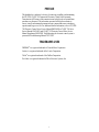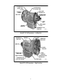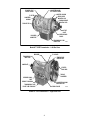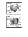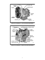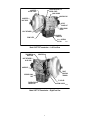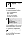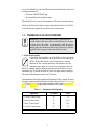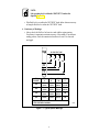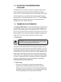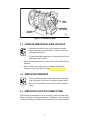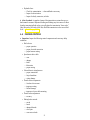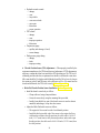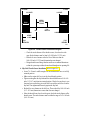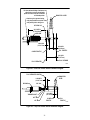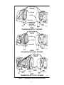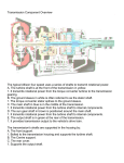
1
Mechanic’s Tips
HT, HTB, CLT, CLBT 700 Series
Electronic Control Transmissions
MT1958EN
MT1958EN
Mechanic’s
Tips
Allison Transmission
HT, HTB, CLT, CLBT 700 Series
Division of General Motors Corporation
P.O. Box 894 Indianapolis, Indiana 46206-0894
Printed in U.S.A.
March, 1995
Revision 1, 1999 April
Copyright © 1995 General Motors Corp.
i
WARNINGS, CAUTIONS, AND NOTES
IT IS YOUR RESPONSIBILITY to be completely familiar with the warnings and
cautions described in this handbook. It is, however, important to understand that these
warnings and cautions are not exhaustive. Allison Transmission could not possibly
know, evaluate, and advise the service trade of all conceivable ways in which service
might be done or of the possible hazardous consequences of each way. Consequently,
Allison Transmission has not undertaken any such broad evaluation. Accordingly,
ANYONE WHO USES A SERVICE PROCEDURE OR TOOL WHICH IS NOT
RECOMMENDED BY ALLISON TRANSMISSION MUST first be thoroughly
satisfied that neither personal safety nor equipment safety will be jeopardized by the
service methods selected.
Proper service and repair is important to the safe, reliable operation of the equipment.
The service procedures recommended by Allison Transmission and described in this
handbook are effective methods for performing service operations. Some of these
service operations require the use of tools specially designed for the purpose. The
special tools should be used when and as recommended.
Three types of headings are used in this manual to attract your attention. These
warnings and cautions advise of specific methods or actions that can result in personal
injury, damage to the equipment, or cause the equipment to become unsafe.
WARNING: A warning is used when an operating procedure, practice,
etc., if not correctly followed, could result in personal injury or loss of life.
CAUTION: A caution is used when an operating procedure,
practice, etc., if not strictly observed, could result in damage to or
destruction of equipment.
NOTE:
A note is used when an operating procedure, practice, etc., is
essential to highlight.
ii
TABLE OF CONTENTS
Paragraph
Description
SECTION I
PREVENTIVE MAINTENANCE
1–1.
1–2.
1–3.
1–4.
1–5.
1–6.
1–7.
1–8.
1–9.
1–10.
1–11.
1–12.
1–13.
SECTION II
2–1.
2–2.
2–3.
2–4.
2–5.
2–6.
SECTION III
3–1.
3–2.
3–3.
3–4.
3–5.
Page
Periodic Inspection and Care . . . . . . . . . . . . . . . . . . . . . . . . . . .
Importance of Proper Transmission Fluid Level . . . . . . . . . . . .
Transmission Fluid Check Procedures. . . . . . . . . . . . . . . . . . . .
Keeping Transmission Fluid Clean . . . . . . . . . . . . . . . . . . . . . .
Automatic Transmission Fluid Recommendations . . . . . . . . . .
Transmission Fluid and Filter Change Intervals . . . . . . . . . . . .
Fluid Temperatures . . . . . . . . . . . . . . . . . . . . . . . . . . . . . . . . . .
High-Efficiency, Main-Pressure External Filter Change . . . . . .
Transmission Fluid Contamination . . . . . . . . . . . . . . . . . . . . . .
Transmission Fluid and Filter Change Procedure . . . . . . . . . . .
Auxiliary Filter. . . . . . . . . . . . . . . . . . . . . . . . . . . . . . . . . . . . . .
Breather . . . . . . . . . . . . . . . . . . . . . . . . . . . . . . . . . . . . . . . . . . .
Transmission Stall Test and Neutral Cool-Down Check . . . . . .
1
1
2
5
5
6
7
8
8
9
9
10
10
REMOVING TRANSMISSION FROM VEHICLE
Draining Transmission . . . . . . . . . . . . . . . . . . . . . . . . . . . . . . . .
Disconnecting Controls . . . . . . . . . . . . . . . . . . . . . . . . . . . . . . .
Uncoupling From Driveline, Engine, and Vehicle. . . . . . . . . . .
Removing the Transmission. . . . . . . . . . . . . . . . . . . . . . . . . . . .
Removing Input and Output Flanges or Yokes . . . . . . . . . . . . .
Rebuild, Overhaul Instructions . . . . . . . . . . . . . . . . . . . . . . . . .
13
13
14
14
14
15
PREPARING THE TRANSMISSION
FOR INSTALLATION
Checking Input Components . . . . . . . . . . . . . . . . . . . . . . . . . . .
Installing Output Flange and Input Flange
(Remote-Mounted Transmission) . . . . . . . . . . . . . . . . . . . . . . .
Installing PTO . . . . . . . . . . . . . . . . . . . . . . . . . . . . . . . . . . . . . .
Installing Transmission Fill Tube and Seal . . . . . . . . . . . . . . . .
Checking Plugs, Openings . . . . . . . . . . . . . . . . . . . . . . . . . . . . .
iii
16
16
17
18
18
Paragraph
Description
SECTION IV
PREPARING VEHICLE FOR TRANSMISSION
INSTALLATION
4–1.
4–2.
4–3.
4–4.
4–5.
4–6.
SECTION V
5–1.
5–2.
5–3.
5–4.
5–5.
5–6.
5–7.
5–8.
5–9.
5–10.
5–11.
5–12.
5–13.
5–14.
SECTION VI
6–1.
6–2.
SECTION VII
7–1.
7–2.
Page
Engine, Transmission Adaptation Requirements. . . . . . . . . . . .
Checking Flexplate Drive Assembly . . . . . . . . . . . . . . . . . . . . .
Checking Input Drive Components
(Remote-Mounted Transmissions). . . . . . . . . . . . . . . . . . . . . . .
Chassis and Driveline Inspection . . . . . . . . . . . . . . . . . . . . . . . .
Cooler, Filter, and Lines . . . . . . . . . . . . . . . . . . . . . . . . . . . . . .
Checking Controls . . . . . . . . . . . . . . . . . . . . . . . . . . . . . . . . . . .
19
20
20
22
22
23
INSTALLING TRANSMISSION INTO VEHICLE
Handling. . . . . . . . . . . . . . . . . . . . . . . . . . . . . . . . . . . . . . . . . . .
Mounting to Engine . . . . . . . . . . . . . . . . . . . . . . . . . . . . . . . . . .
Installing Transmission Mounting Components . . . . . . . . . . . .
Coupling to Driveline. . . . . . . . . . . . . . . . . . . . . . . . . . . . . . . . .
Coupling to Engine (Remote-Mounted Transmission) . . . . . . .
Connecting Input Retarder Control . . . . . . . . . . . . . . . . . . . . . .
Connecting Output Retarder Control . . . . . . . . . . . . . . . . . . . . .
Connecting Power Takeoff Controls . . . . . . . . . . . . . . . . . . . . .
Connecting Parking Brake Control . . . . . . . . . . . . . . . . . . . . . .
Connecting Cooler, Filter. . . . . . . . . . . . . . . . . . . . . . . . . . . . . .
Installing Auxiliary Filter. . . . . . . . . . . . . . . . . . . . . . . . . . . . . .
Connecting Speedometer Drive . . . . . . . . . . . . . . . . . . . . . . . . .
Installing Temperature and Pressure Sensors,
Connecting Electrical Components . . . . . . . . . . . . . . . . . . . . . .
Filling the Hydraulic System . . . . . . . . . . . . . . . . . . . . . . . . . . .
27
27
28
28
28
29
29
29
30
30
30
30
32
32
CHECKS AND ADJUSTMENTS
Installation Checklist . . . . . . . . . . . . . . . . . . . . . . . . . . . . . . . . . 33
Road Test and Vehicle Operation Checklist . . . . . . . . . . . . . . . 35
CUSTOMER SERVICE
Owner Assistance. . . . . . . . . . . . . . . . . . . . . . . . . . . . . . . . . . . . 37
Service Literature . . . . . . . . . . . . . . . . . . . . . . . . . . . . . . . . . . . . 39
iv
PREFACE
This handbook is a mechanic’s reference for removing, installing, and maintaining
the HT, HTB, CL(B)T 700 Commercial Electronic Control Series Automatic
Transmissions. All features of the transmission and vehicle involved in installation
procedures are discussed. The information presented will help the mechanic to
remove, install, and maintain the transmission in a manner that assures satisfactory
operation and long service life. For additional detailed information, refer to HT, HTB
700 Electronic Control Series Service Manual SM2004EN or CL(B)T 700 Series
Service Manual SM1314EN and CL(B)T 755 Electronic Control Series Service
Manual Supplement SM1992EN. Troubleshooting the electronic control system is
presented in Troubleshooting Manual TS2712EN.
TRADEMARKS USED
DEXRON® is a registered trademark of General Motor Corporation.
Loctite® is a registered trademark of the Loctite Corporation.
Teflon® is a registered trademark of the DuPont Corporation.
Pro-Link® is a registered trademark of Micro Processor Systems, Inc.
v
FLYWHEEL BOLT
ACCESS COVER
CONVERTER-DRIVEN
PTO ACCESS COVER
TO FILTER
REAR COVER
MOUNTING PAD
CONVERTER
HOUSING
PARKING BRAKE
MOUNTING PAD
FROM FILTER
OUTPUT
SHAFT
SPEED SENSOR
PICKUP
BULKHEAD
CONNECTOR
TRANSMISSION FLUID
H01932
DRAIN PLUG
Model HT 741, 748 Transmission — Left-Rear View
TRANSMISSION
MAIN CASE
BREATHER
TO COOLER
TEMPERATURE
SENSOR PORT
NAMEPLATE
STARTER
RING GEAR
REVERSE SIGNAL
SWITCH PORT
TORQUE
CONVERTER
PREHEAT PROVISION
CONVERTER HOUSING
MOUNTING PAD
TRANSMISSION FLUID
FILLER TUBE PROVISION
FROM COOLER
Model HT 741, 748 Transmission — Right-Front View
vi
H01933
FLYWHEEL BOLT
ACCESS COVER
CONVERTER-DRIVEN
PTO ACCESS COVER
ADAPTER HOUSING
TO FILTER
REAR COVER
MOUNTING PAD
PARKING BRAKE
MOUNTING PAD
CONVERTER
HOUSING
FROM FILTER
OUTPUT
SHAFT
SPEED SENSOR
PICKUP
BULKHEAD
CONNECTOR
TRANSMISSION FLUID
DRAIN PLUG
H01934
Model HT 755CR Transmission — Left-Rear View
TRANSMISSION
MAIN CASE
BREATHER
TO COOLER
TEMPERATURE
SENSOR PORT
NAMEPLATE
STARTER
RING GEAR
TORQUE
CONVERTER
REVERSE SIGNAL
PORT
PREHEAT PROVISION
CONVERTER HOUSING
MOUNTING PAD
FROM COOLER
H01935
TRANSMISSION FLUID
FILLER TUBE PROVISION
Model HT 755CR Transmission — Right-Front View
vii
ENGINE-DRIVEN TOP
PTO ACCESS COVER
INPUT RETARDER BRAKE OPTION
CONVERTER-DRIVEN PTO
ACCESS COVER
REAR COVER
MOUNTING PAD
TO FILTER
CONVERTER
HOUSING
PARKING BRAKE
MOUNTING PAD
FROM FILTER
OUTPUT
SHAFT
ENGINE-DRIVEN
LEFT SIDE PTO
ACCESS COVER
BULKHEAD
CONNECTOR
SPEED SENSOR
PICKUP
ADAPTER HOUSING
TRANSMISSION FLUID
DRAIN PLUG
H01936
Model HT 755DR Transmission — Left-Rear View (With Input Retarder)
TRANSMISSION
MAIN CASE
BREATHER
STARTER RING
GEAR
TEMPERATURE
SENSOR PORT
FLYWHEEL
NAMEPLATE
TORQUE
CONVERTER
REVERSE SIGNAL
PORT
PREHEAT PROVISION
TRANSMISSION FLUID
FILLER TUBE PROVISION
INPUT RETARDER
VALVE BODY
CONVERTER HOUSING
MOUNTING PAD
TO COOLER
H01937
FROM COOLER
Model HT 755DR Transmission — Right-Front View (With Input Retarder)
viii
CONVERTER
HOUSING
TO FILTER
PTO ACCESS COVER
ADAPTER HOUSING
FLYWHEEL
GOVERNOR
COVER
STARTER
RING GEAR
BULKHEAD
CONNECTOR
FROM FILTER
H01938
Model HTB 748 Transmission — Left-Front View (With Output Retarder)
RETARDER PISTON
APPLY LINE
RETARDER CONTROL AIR PRESSURE ADAPTER
FROM COOLER
SENSOR
TO COOLER
(CONVERTER-OUT)
RETARDER
HOUSING
LUBE PORT
(FROM COOLER)
NAMEPLATE
TO COOLER
ACCUMULATOR
TRANSMISSION FLUID
FILLER TUBE PROVISION
RETARDER VALVE BODY
TEMPERATURE PROBE
PROVISION
REGULATOR VALVE BODY
H01939
Model HTB 748 Transmission — Right-Rear View (With Output Retarder)
ix
CONVERTER-DRIVEN PTO
ACCESS COVER
MAIN HOUSING
CONVERTER
ACCESS COVER
MOUNTING PAD
CONVERTER
INPUT DRIVE
OUTPUT
FLANGE NUT
SPEED SENSOR
PICKUP
INPUT RETARDER
BULKHEAD
CONNECTOR
FROM FILTER
8 1⁄ 2 in. CASTIRON
OIL PAN
H01940
Model CLBT 755 Transmission — Left-Front View
TRANSMISSION
MAIN CASE
BREATHER
INPUT RETARDER
VALVE BODY
NAMEPLATE
FRONT
MOUNTING
TRUNNION
REVERSE SIGNAL
PORT
TO COOLER
TEMPERATURE
SENSOR PORT
FROM COOLER
H01941
Model CLBT 755 Transmission — Right-Front View
x
PREVENTIVE
MAINTENANCE
S ECTION
I
1–1. PERIODIC INSPECTION AND CARE
Clean and inspect the exterior of the transmission at regular intervals. Severity of
service and operating conditions determine the frequency of these inspections.
Inspect the transmission for:
•
•
•
•
•
•
loose bolts — transmission and mounting components
fluid leaks — repair immediately
loose, dirty, or improperly adjusted throttle sensor linkage
damaged or loose hoses
worn, frayed, or improperly routed electrical harnesses
worn or out-of-phase driveline U-joints and slip fittings
CAUTION: When welding on the vehicle:
• DO NOT WELD on the vehicle without disconnecting from
the ECU all control system wiring harness connectors.
• DO NOT WELD on the vehicle without disconnecting ECU
battery power and ground leads.
• DO NOT WELD on any control components.
• DO NOT CONNECT welding cables to any control components.
A label describing on-vehicle welding precautions is available from your authorized
Allison service dealer and should be installed in a conspicuous place. A vehicle used
in a vocation that requires frequent modifications or repairs involving welding must
have an on-vehicle welding label.
1–2. IMPORTANCE OF PROPER TRANSMISSION FLUID LEVEL
Because the transmission fluid cools, lubricates, and transmits hydraulic
power, it is important that the proper fluid level be maintained at all times.
If the fluid level is too low, the torque converter and clutches will not
receive an adequate supply of transmission fluid, and the transmission
will overheat. If the fluid level is too high, the fluid aerates — causing the transmission
to shift erratically and overheat. Fluid may be expelled through the breather or
dipstick tube when the fluid level is too high.
1
A severely low fluid level causes the Allison Transmission Electronic Control to do
two things automatically —
• Turn on the CHECK TRANS light
• Prevent upshifting into the highest range
When the fluid level is corrected, the transmission will return to normal operation.
Do not use the Electronic Control to replace regular fluid level checks. Check the
level at the intervals specified in your vehicle service instructions.
1–3. TRANSMISSION FLUID CHECK PROCEDURES
WARNING: Take the following precautions so that unexpected,
possible sudden vehicle movement is avoided. Whenever it becomes
necessary to leave the vehicle, even momentarily, while the engine is
running, place the transmission shift selector in Neutral, set the parking brake and/or emergency brakes and chock the wheels.
a. Fluid Check Procedure.
Clean all dirt from around the end of the fill tube before removing the
dipstick. Do not allow the dirt or any foreign matter to enter the
transmission. Dirt or foreign matter may cause undue wear of the
transmission parts, make valves stick, and clog passages. Check the
fluid level, manually, using the following procedure and record the level in your
maintenance log. To perform the fluid level check, the engine must be running at
idle speed and the transmission must be in N (Neutral).
Add transmission fluid to the transmission through the fill tube opening. Be sure to
use proper transmission fluid and fluid containers as discussed in Sections 1–4 and
1–5. Refer to Table 1–1 for approximate transmission fluid capacity.
Table 1–1. Transmission Fluid Capacity
Application
U.S. Quarts
Liters
34
32
6 inch (152 mm) oil pan
30
28.5
7 inch (178 mm) oil pan
30
28.5
81 ⁄ 2
43
41
41 ⁄ 2
inch (114 mm) oil pan
inch (215 mm) oil pan
NOTE: Does not include external circuits.
2
b. Cold Check.
NOTE:
The purpose of the Cold Check is to determine if the transmission
has enough fluid to be safely operated until a hot check can be
made.
• Park the vehicle on a level surface. Apply the parking brake, and chock the
wheels.
CAUTION: The fluid level rises as fluid temperature increases.
DO NOT fill above the “COLD RUN” band if the transmission fluid is
below normal operating temperatures.
• Run the engine for at least one minute. Shift to D (Drive) and then to
R (Reverse) to clear the hydraulic circuits of air. Then shift to N (Neutral) and
allow the engine to idle (500–800 rpm).
• Insert the dipstick into the tube and remove. Check the fluid level reading.
Repeat the check procedure to verify the reading.
• If the fluid level is within the “COLD RUN” band, the transmission may be
operated until the fluid is hot enough to perform a “HOT RUN” check. If the
fluid level is not within the “COLD RUN” band, add or drain as necessary to
bring it to the middle of the “COLD RUN” band.
• Perform a hot check as soon as the normal operating temperature of
160–200°F (71–93°C) is reached.
c. Hot Check.
CAUTION: The transmission fluid must be hot to ensure an accurate
check. The fluid level rises as temperature increases.
• Operate the transmission in D (Drive) until normal operating temperature is
reached:
160–200°F (71–93°C) sump temperature
180–220°F (82–104°C) converter-out temperature
• Park the vehicle on a level surface and shift to N (Neutral). Apply the parking
brake, and chock the wheels. Allow the engine to idle.
• With the engine running, remove the dipstick from the tube and wipe it clean.
• Insert the dipstick into the tube and remove. Check fluid level reading. Repeat
the check procedure to verify the reading.
3
NOTE:
Safe operating level is within the “HOT RUN” band on the
dipstick, Figure 1–1.
• If the fluid level is not within the “HOT RUN” band, add or drain as necessary
to bring the fluid level to within the “HOT RUN” band.
d. Consistency of Readings.
• Always check the fluid level at least twice and with the engine running.
Consistency is important to maintain accuracy of the reading. If inconsistent
reading persists, check the transmission breather to be sure it is clean and
unclogged.
OIL PAN SPLIT LINE
B
D
✽C
COLD
RUN
HOT
RUN
A
HT/CT
PAN SIZE
4.50"
6.00"
7.00"
8.50"
DIM
A
25.4 mm
(1.00 IN.)
38.1 mm
(1.50 IN.)
63.5 mm
(2.50 IN.)
63.5 mm
(2.50 IN.)
DIM
B
38.1 mm
(1.50 IN.)
63.5 mm
(2.50 IN.)
88.9 mm
(3.50 IN.)
88.9 mm
(3.50 IN.)
DIM
C✽
50.8 mm
(2.00 IN.)
95.3 mm
(3.75 IN.)
120.7 mm
(4.75 IN.)
120.7 mm
(4.75 IN.)
✽ Approximate Dimension, OEM/Customer is to establish
COLD RUN BAND at installation.
Figure 1–1. Typical Dipstick Markings
4
DIM
D
44.5 mm
(1.75 IN.)
76.2 mm
(3.00 IN.)
N/A
N/A
V01889
1–4. KEEPING TRANSMISSION FLUID CLEAN
CAUTION: Containers or fillers that have been used for any antifreeze or engine coolant solution must not be used for the transmission fluid. Antifreeze and coolant solutions contain ethylene glycol
which, if introduced into the transmission, can cause the clutch plates
to fail.
Transmission fluid must be handled in clean containers, fillers, etc., to prevent
foreign material from entering the transmission. Clean around the filler tube before
removing the dipstick. Lay the dipstick in a clean place while filling the
transmission.
1–5. AUTOMATIC TRANSMISSION FLUID RECOMMENDATIONS
• Hydraulic fluids (oils) used in the transmission are important influences on
transmission performance, reliability and durability. DEXRON®-III fluid is
recommended for light-duty applications. Type C-4 fluids are recommended
for severe-duty applications.
• Some DEXRON®-III fluids are also qualified as Type C-4 fluids. To ensure the
fluid is qualified for use in Allison transmissions, check for a DEXRON®-III or
C-4 fluid license, or approval numbers on the container, or consult the lubricant
manufacturer. Consult your Allison Transmission dealer or distributor before
using other fluid types; fluid types such as Type F, and universal farm fluids may
or may not be properly qualified for use in your Allison transmission.
CAUTION: Disregarding minimum fluid temperature limits can
result in transmission malfunction or reduced transmission life.
• When choosing the optimum viscosity grade of fluid to use, duty cycle,
preheat capabilities, and/or geographical location must be taken into
consideration. Table 1–2 lists the minimum fluid temperatures at which the
transmission may be safely operated. Preheat with auxiliary heating
equipment or by running the vehicle with the transmission in N (Neutral) for a
minimum of 20 minutes before attempting range operation.
5
Table 1–2.
Operating Temperature Requirements for Transmission Fluid
Viscosity Grade
DEXRON®-III
SAE 10W
SAE 15W-40
SAE 30
SAE 40
Ambient Temperature Below
Which Preheat Is Required
Fahrenheit
Celsius
–17
–27
–4
5
32
50
–20
–15
0
10
Ref. 13-TR-90.
1–6. TRANSMISSION FLUID AND FILTER CHANGE INTERVALS
a. Frequency.
Transmission fluid and filter change frequency is determined by severity of
transmission service and by the filter equipment installed. Table 1–3 is a
general guide. More frequent changes may be required when operating
conditions create high levels of contamination or overheating.
Table 1–3. Transmission Fluid and Filter Change Intervals
Fluid Change Interval
50,000 miles (80 000 km)
or 12 months or 1200
hours*
Internal Sump
and Governor
Filter
At overhaul
Standard Main Pressure
External Filter**
After first 5000 miles (8 000 km) and
at each 25,000 miles (40 000 km) or
6 months or 600 hours, thereafter*
* Whichever occurs first.
** An Allison high efficiency filter may be used until the change filter light indicates it is
contaminated or until it has been in use for three years, whichever occurs first. No mileage
restrictions apply.
b. Abnormal Conditions. Transmission fluid must be changed whenever there
is evidence of dirt or a high temperature condition. A high temperature condition is
indicated by the transmission fluid being discolored or having a strong odor, or by
fluid analysis. Local conditions, severity of operation, or duty cycle require more or
less frequent fluid or filter change intervals.
6
c. Fluid Analysis. Transmission protection and fluid change intervals can be
optimized by monitoring fluid oxidation according to the tests and limits shown in the
Table 1–4. Consult your telephone directory for fluid analysis firms. To ensure consistent
and accurate fluid analysis, select only one fluid analysis firm. Refer to
the latest edition of GN2055EN, Technician’s Guide for Automatic Transmission Fluids.
Table 1–4.
Fluid Oxidation Measurement Limits
Measurement
Limit
Viscosity
±25% change from new fluid
Carbonyl absorbance
+0.3 A*/0.1 mm change from new fluid
Total acid number
+3.0 change from new fluid
Solids
2% by volume maximum
* Note: A = Absorbance units.
1–7. FLUID TEMPERATURES
• If the sensor is located in the converter housing or input retarder valve, the
critical temperatures are listed in the converter-out column. If the sensor is
located in some other area, refer to the vehicle manual for the critical
temperatures. If the maximum fluid temperature is reached, follow this
procedure:
— Stop the vehicle and shift the transmission into N (Neutral) and
operate the engine at 1500 rpm to reduce the transmission fluid
temperature.
— If the transmission fluid does not cool in approximately 30 seconds,
or if it continues to overheat after operation is continued, stop the
vehicle and engine and locate the problem.
Table 1–5.
Fluid Temperatures
Condition
Converter-Out
Converter Operation
— CLBT 700 Series
— HT 700 Series
275˚F (135˚C) max
300˚F (149˚C) max
Retarder Operation
— Intermittent
330˚F (166˚C) max
Lockup Operation
250˚F (121˚C) max
Normal Operation
180–220˚F (82–105˚C)
7
1–8. HIGH-EFFICIENCY, MAIN-PRESSURE EXTERNAL
FILTER CHANGE
Allison high-efficiency external filters, which have a change filter indicator, do not
need to be changed when the transmission fluid is changed unless restriction is
indicated. There is no mileage limitation with the use of Allison high-efficiency filters.
An Allison high-efficiency external filter element must be changed if the engine
and transmission are at operating temperature (over 160°F; 71°C) and the Change
Filter light is illuminated for any length of time or the element has not been
changed for three years, whichever occurs first.
1–9. TRANSMISSION FLUID CONTAMINATION
a. Examine At Fluid Change. At each transmission fluid change, examine the fluid
that is drained for evidence of dirt or water. A normal amount of condensation will
emulsify in the fluid during operation of the transmission. However, if there is evidence of water, check the cooler (heat exchanger) for leakage between the water and
fluid areas. Fluid in the water side of the cooler (heat exchanger) is another sign of
leakage. This, however, may indicate leakage from the engine oil system.
b. Metal Particles.
CAUTION: If excessive metal contamination has occurred, replace
the cooler and all bearings within the transmission.
Metal particles in the transmission fluid or on the magnetic drain plug (except for
the minute particles normally trapped in the filter) indicate damage has occurred in
the transmission. When these particles are found in the sump, the transmission must
be disassembled and closely inspected to find the source. Metal contamination will
require complete disassembly of the transmission and cleaning of all internal and
external circuits, cooler, and all other areas where the particles could lodge. During
the repair of a major internal failure of a transmission, it should be dismantled into
as many serviceable detail parts as possible and thoroughly cleaned. Do not
disassemble the unit just to the problem area.
c. Coolant Leakage.
• The presence of ethylene glycol coolant in the transmission fluid is
detrimental to the reliability and durability of the internal components.
Ethylene glycol has a deteriorating effect on friction-faced clutch plates and
nonmetallic components (seals, gasket, etc.) and on highly loaded steel parts,
such as bearings and gears, due to reduced lubricity of the fluid.
8
d. If the presence of ethylene glycol in the fluid is suspected, immediately perform
a verification test. A Gly-Tek test kit is available and is a quick and easy method to
determine the presence of glycol. If glycol is found, disassemble and inspect the
transmission, and remove all traces of coolant and varnish deposits resulting from
coolant contamination. Replace all seals, gaskets, and friction-faced clutch plates.
Repair or replace the cooler prior to installation of the new or rebuilt transmission.
1–10. TRANSMISSION FLUID AND FILTER CHANGE PROCEDURE
NOTE:
Do not drain the transmission fluid if only filters are being
replaced.
a. Drain Fluid.
• Drain the fluid when the transmission is at operating temperature —
160–200°F (71–93°C). Hot fluid flows quicker and drains thoroughly.
• Remove the drain plug from the oil pan and allow the fluid to drain into
a suitable container.
• Examine the fluid as described in the Section 1–8.
b. Replace Filters.
• Refer to the latest edition of the HT 700 Series Service Manual SM2004EN
for complete procedures for replacement of the filter.
• Remove the oil pan, and replace the old filter with the new one.
c. Refill Transmission. The amount of refill fluid is less than the amount used
for the initial fill. Fluid remains in the external circuits and transmission cavities
after draining the transmission. After refill, check the fluid level using the procedure
described in Section 1–3.
1–11. AUXILIARY FILTER
• If a condition occurs that introduces debris into the transmission hydraulic
system, a complete cleanup of the cooler and lines is required.
• Because repeated cleaning and flushing may not remove all debris, install an
auxiliary filter in the cooler-out circuit (models without an output retarder), or
in the lubrication circuit (models with an output retarder). This
recommendation applies whether the transmission is overhauled or replaced
by a new or rebuilt unit.
• If any doubt exists about the cleanup of the cooler, replace the cooler.
9
• The auxiliary filter must have at least a 40-micron filter element or finer and a
maximum filter pressure drop of 2 psi (14 kPa) at 15 gpm (57 liters/minute) at
180˚F (82˚C). The maximum external circuit pressure drop must not exceed
30 psi (207 kPa) at 15 gpm (57 liters/minute) at operating temperature, in
D (Drive) at full throttle stall.
• The following auxiliary filters are recommended:
Table 1–6.
Auxiliary Filter Recommendations
Filter Assembly
Allison 29510921*
AC PM 13-16
AC PM 16-1
FX 11583
Fram HP 1-1
Purolator OF-15C-1
Purolator 20-10
Filter Element
Allison 29510918*
PF 897
PF141
HF6520
HP 1 or AC HD 222
OF-2C-1
PER-20
* High-efficiency filter and element are available from your authorized Allison distributor.
Ref: SIL 12-TR-93 (latest revision)
1–12. BREATHER
a. Location and Purpose. The breather is located on top of the transmission hous-
ing. The breather prevents air pressure buildup within the transmission and its passage must be kept clean and open.
b. Maintenance. The amount of dust and dirt encountered will determine the fre-
quency of breather cleaning. Use care when cleaning the transmission. DO NOT
SPRAY STEAM, WATER, OR CLEANING SOLUTION DIRECTLY AT THE
BREATHER. Spraying steam, water, or cleaning solution directly at the breather
can force the water or cleaning solution into the transmission.
c. Replacement. Always use a wrench of the proper size to remove or replace the
breather. Pliers or a pipe wrench can crush or damage the stem and produce metal chips
which could enter the transmission. Tighten the breather to 9–12 lb ft (12–16 N·m).
1–13. TRANSMISSION STALL TEST AND NEUTRAL
COOL-DOWN CHECK
WARNING: When conducting a transmission stall test, the vehicle
must be prevented from moving. Apply the parking brake and service
brakes and block the vehicle securely. Warn personnel to keep clear of
the vehicle and its travel path. Failure to do so can cause serious injury.
10
a.
Purpose.
The stall test provides a method for determining if the malfunction
is in the engine or in the transmission when a vehicle is not performing
satisfactorily.
The neutral cool-down check utilizes the two-minute cooling period on the stall test
to gather transmission fluid temperature data for troubleshooting reference.
b. Transmission Stall Test Procedure. The engine stall point (rpm) under load
is compared to the engine manufacturer’s specified rpm for the stall test.
NOTE:
The engine manufacturer’s test data must be available for the
stall test. This data can be obtained from the engine
manufacturer, or from your equipment dealer or distributor.
• Connect a tachometer of known accuracy to the engine and install a
temperature probe into the converter-out (to cooler) line. Bring the
transmission to the normal operating temperature 160–200°F (71–93°C).
CAUTION: Do not attempt to stall test any transmission in reverse
range. Do not attempt to stall test the 755DR Series transmission in
first (low) gear. The torque produced in that gear can damage the
vehicle driveline.
• On the 755 Series transmissions, shift the selector to D (Drive) range or utilize
the optional stall check feature. On the 741 or 748 Series, shift to any forward
range.
CAUTION: Never maintain the stall condition for more than 30
seconds at any one time because of the rapid rise in transmission fluid
temperature. Do not let the converter-out temperature exceed 300°F
(149°C). Do not rely on converter-out temperature to limit stall
duration. During stall conditions, internal temperatures rise much
faster than converter-out temperature. If the stall test is repeated, do
not let the engine overheat.
• With the vehicle blocked, parking brake and service brake applied, hold the
engine at wide-open throttle. When the converter-out temperature reaches
a minimum of 255°F (124°C), record the engine speed.
• Reduce engine speed to idle and shift to N (Neutral).
11
c. Neutral Cool-Down Check Procedure. The neutral cool-down check determines
if the transmission fluid cools following an engine load condition. Perform this check
immediately after the engine speed has been recorded in the stall test.
• Record the converter-out temperature.
• With the transmission remaining in Neutral, run the engine at 1200–1500 rpm
for two minutes to cool the transmission fluid.
• At the end of two minutes, record the converter-out temperature.
d. Results.
NOTE:
Environmental conditions, such as ambient temperature, altitude,
engine accessory loss variations, etc., affect the power input to the
converter. Under such conditions, a stall speed deviation within
±150 rpm of specification can be accepted as within normal range.
If engine stall speed is more than 150 rpm below the stall speed specified by the
engine manufacturer, an engine problem is indicated, such as need for tune-up.
If engine stall speed is more than 150 rpm above specification, a transmission
problem is indicated, such as slipping clutches, cavitation, or torque converter
failure. Refer to Section 2–6 for the applicable service manual number.
An extremely low stall speed, such as 33 percent of the specified engine stall rpm,
during which the engine does not smoke, could indicate a freewheeling stator.
If the engine stall speed conforms to specification, but the transmission fluid
overheats, refer to the cool-down check. If the transmission fluid does not cool
during the two-minute cool-down check, a stuck stator can be indicated.
If the engine stall speed conforms to specification and the cool-down check shows
that transmission fluid cools properly, refer to Troubleshooting Manual TS2712EN.
12
REMOVING
TRANSMISSION
FROM VEHICLE
S ECTION
II
2–1. DRAINING TRANSMISSION
Drain the transmission fluid before the transmission is removed from the vehicle.
• Remove the drain plug from the oil pan. Examine the drained transmission
fluid for evidence of contamination (see Section 1–9). Reinstall the drain
plug.
• Remove transmission fluid fill tube if it interferes with transmission removal.
NOTE:
A significant amount of transmission fluid may drain from the
hydraulic lines when they are disconnected from the transmission.
• Disconnect all other hydraulic lines from the transmission. Remove the lines
from the vehicle if they will interfere with the transmission removal. Plug all
hose openings to keep dirt from entering the hydraulic system.
2–2. DISCONNECTING CONTROLS
• Disconnect or completely remove the electronic controls. If controls are not
removed from the transmission, position them so they do not interfere with
transmission removal.
• Disconnect the electronic control chassis harness from the transmission main
connector and from the speed sensor connector (Figure 2–1).
• If an external pressure switch for a reverse signal is used, disconnect vehicle
harness from switch.
• Disconnect the speedometer drive cable, if used.
• Disconnect the air supply line at the output retarder control valve (if output
retarder is used).
• Disconnect the input retarder control linkage (if input retarder is used).
13
SPEED
SENSOR
SPEEDOMETER
DRIVE OPENING
BULKHEAD
CONNECTOR
L01498.01
Figure 2–1. Disconnect Locations
2–3. UNCOUPLING FROM DRIVELINE, ENGINE, AND VEHICLE
• Disconnect the vehicle driveline from the transmission output
flange. Position the disconnected shaft to avoid interference when
removing the transmission.
• If transmission mounts support the rear of the engine, place a jack or
other support under the engine.
• Support the transmission securely on a hoist, jack, or other suitable removal
equipment.
• Remove all bolts, nuts, washers, spacers, and supports that attach the
transmission to the vehicle and to the engine (reference Figure 4–1).
2–4. REMOVING THE TRANSMISSION
• Move the transmission away from the engine until it is completely
clear of the engine. If used, remove the adapter ring and/or gasket.
• Raise or lower the transmission as necessary to remove it from the
vehicle.
2–5. REMOVING INPUT AND OUTPUT FLANGES OR YOKES
When replacing the transmission, it may be necessary to transfer input and output
flanges or yokes to the replacement transmission. If the flanges or yokes are retained
by a large self-locking nut, follow specific procedures below for removal of the nut.
14
CAUTION: The use of an impact wrench for removing the input or
output nut requires a means to hold the flange. Failure to hold the
flange can cause internal damage to the transmission.
• Before removing the self-locking nut, check to see if there are any notches cut
into the wrenching flats. If there are five notches, remove the nut and throw it
away.
• If there are less than five notches or none at all, remove dirt and burrs from the
shaft thread. Then loosen the nut until there is about 1⁄16 inch gap between the
nut and flange.
• Check the running torque as the nut is being removed. The first time the nut is
removed (no notches), running torque must be at least 400 lb in. (45 N·m).
Each additional time the nut is removed (one to four notches), running torque
must be at least 300 lb in. (34 N·m). Discard the nut if it does not meet the
running torque limit.
2–6. REBUILD, OVERHAUL INSTRUCTIONS
Refer to the latest edition of the following Service Manuals for rebuild or overhaul
of the transmission:
— HT, HTB 700 Electronic Control Series Service Manual SM2004EN
— CL(B)T 700 Series Service Manual SM1314EN, with CL(B)T 755
Electronic Control Series Service Manual Supplement SM1992EN
15
S ECTION
III
PREPARING THE
TRANSMISSION FOR
INSTALLATION
3–1. CHECKING INPUT COMPONENTS
a. Bolt Holes. Check all bolt holes on the front of the flywheel/converter/flexplate
adapter. The threads must be undamaged, and the holes must be free of any chips or
foreign materials.
b. Pilot Boss. Check the pilot boss (at center of flywheel) for damage or raised
metal which could prevent bolt free entry into the flex disk hub (adapter).
c. Starter Ring Gear. Check the starter ring gear for excessive wear or damage.
d. Transmission Mounting Flange. Check the transmission mounting flange for
raised metal, dirt, or pieces of gasket material.
e. Transmission-To-Engine Mounting Flange. Inspect the transmission-to-engine
mounting flange for raised metal, burrs, or pieces of gasket material. Also inspect
the threaded holes for damaged threads.
3–2. INSTALLING OUTPUT FLANGE AND INPUT FLANGE
(REMOTE-MOUNTED TRANSMISSION)
a. Output Oil Seal. Check the output flange rear oil seal and input front flange oil
seal for leaks or damage. Replacement instructions are in the HT, HTB 700 Electronic Control Series Service Manual SM2004EN, and CL(B)T Series Service Manual SM1314EN with CL(B)T 755 Electronic Control Series Service Manual
Supplement SM1992EN. Lubricate the oil seals with high-temperature grease or
transmission fluid.
b. Check Yoke. Inspect each flange or yoke for damage or wear. The oil seal contact surface must be smooth and regular to prevent transmission fluid leaking past
the seal. Rotate the flange during installation to avoid seal lip damage.
c. Installing the Parking Brake. Install the parking brake assembly on the parking
brake mounting pads on the transmission, and tighten the bolts to the vehicle manufacturer specifications.
d. Installing Output Yoke. Install the rear output yoke on the rear output shaft.
16
3–3. INSTALLING PTO
Access to the PTO mounting pads and the space available to maneuver the
transmission determine whether the PTO should be installed before or after the
transmission is installed.
CAUTION: DO NOT use cork or other soft gaskets to install the
PTO. Use only the shims/gaskets listed in the appropriate parts
catalog of your transmission model.
NOTE:
DO NOT use sealing compounds — they are usually incompatible
with automatic transmission fluid.
a. Install Guide Pins — Included in the PTO Installation Kit. Determine the re-
quired position of the guide pins in relation to the mounted position of the PTO. The
guide pins must align with the two blind holes in the PTO. Install two headless guide
pins into the converter-housing PTO pad. Tighten the pins.
b. Determine the Backlash and Proper Gasket/Shim. You might have a turbine-
driven PTO or an engine-driven PTO.
• For the turbine-driven PTO, the prescribed backlash between the drive gear
(in the transmission) and the driven gear (in the PTO) is 0.018–0.024 inch
(0.46–0.60 mm) prior to S/N 32404, and 0.006–0.029 inch (0.16–0.73 mm)
after S/N 32403 models.
• For the engine-driven PTO, the prescribed backlash is 0.006–0.029 inch
(0.16–0.73 mm).
• Refer to the latest edition of Service Manual SM2004EN for the description
of the method to determine the backlash. Establish proper backlash by
selecting proper thickness of shims (gaskets).
c. Mount the PTO. Mount the PTO on the guide pins, meshing the PTO driven
gear with the PTO drive gear. Retain the PTO by installing a bolt in the top bolt hole.
Install the remaining bolts. Tighten the bolts to 51–61 N.m (38–45 lb ft).
CAUTION: PTO units using transmission main pressure to engage
the PTO driven gear must have a positive main pressure shut-off at the
solenoid valve when the PTO is not engaged.
17
3–4. INSTALLING TRANSMISSION FILL TUBE AND SEAL
a. Inspection. Inspect the fill tube for proper vent location and vent hole diameter;
a vent hole should be located on the underside of the tube and just below the seal of
the dipstick, and the diameter should measure 0.060–0.080 inch (1.6–2.0 mm).
b. Location. The filler tube may be mounted on either the left or the right side. The
unused fill tube provision must have an expansion plug installed in the fill tube
opening.
CAUTION: Install the fill tube brackets with the correct length bolt.
Too long a bolt may cause cracks and leaks in the main housing. Refer
to the appropriate HTB 700 Series Parts Catalog PC1965EN or CLT
700 Series Parts Catalog PC1993EN.
c. Installation. Install the fill tube into the main housing. Insert the fill tube
through the seal. Align the tube bracket with its bolt location. Install the fill tube
bolts and tighten to 14–18 lb ft (19–24 N·m).
3–5. CHECKING PLUGS, OPENINGS
Check carefully at all sides of the transmission for loose or missing hydraulic
pressure check plugs.
• The 1⁄8 inch pipe plugs should be tightened to 48–60 lb in. (5.5–6.7 N·m).
• Check the four openings into which the cooler and filter lines connect, for
cleanliness. Remove any closures or obstructions.
• Check the drain plug for tightness. The drain plug must be tightened to 15–20
lb ft (21–27 N·m).
• Check the main electrical connector in the transmission housing for
cleanliness.
18
PREPARING VEHICLE
FOR TRANSMISSION
INSTALLATION
S ECTION
IV
4–1. ENGINE, TRANSMISSION ADAPTATION REQUIREMENTS
You must ensure that a new transmission installation can be adapted to the vehicle’s
engine. The explained measurements in this section ensure correct transmission-toengine adaptation. Refer to Figures 4–1, 4–2, and 4–3.
a. Measuring Equipment. Refer to the following list for the required measuring
equipment.
• 24.0 inches (600 mm) precision caliper
• 2–4 inches (50–100 mm) telescoping gauge
• 1–3 inches (25–76 mm) outside micrometer
• 0–6 inches (0–150 mm) depth micrometer
• Dial indicator and mounting attachments — base, posts, and clamps
b. Flywheel Housing Pilot Bore Diameter. The flywheel housing pilot bore diameter must measure from 20.125–20.130 inches (511.18–511.30 mm).
c. Flywheel Housing Bore Runout. Flywheel housing bore runout cannot exceed
0.020 inch (0.51 mm) TIR.
d. Flywheel Housing Face Squareness. The flywheel housing face cannot be
out-of-square more than 0.020 inch (0.51 mm) TIR.
e. Crankshaft Hub Pilot or Adapter Diameter. The crankshaft hub pilot or hub
adapter pilot diameter must measure between 2.437–2.439 inches (61.90–61.95 mm).
f. Crankshaft Hub Pilot or Adapter Squareness. The crankshaft hub or hub adapt-
er cannot be out-of-square more than 0.005 inch (0.13 mm) TIR.
g. Crankshaft Hub Pilot or Adapter Eccentricity. The crank shaft hub pilot or the
hub adapter cannot be out-of-square more than 0.005 inch (0.13 mm) TIR.
h. Flexplate Bolt Hole Flatness. Flexplate flatness in the area of the bolt holes is not
a measurement required for HT and CT 700 Series flexplates.
i. Torque Converter Axial Location. Refer to Figure 4–2. Using a depth gauge,
measure from the torque converter housing to the torque converter’s flexplate adapter
mounting face. The torque converter axial location should measure 3.592–3.413 inches
(91.24–86.69 mm).
19
4–2. CHECKING FLEXPLATE DRIVE ASSEMBLY
a. Flexplate Inspection. Inspect the flexplate for cracks, wear, distortion, and elon-
gated bolt holes. Replace a damaged part.
b. Engine Crankshaft End Play. Ensure that the crankshaft end play is within the
engine manufacturer’s specifications.
c. Flexplate Assembly Installation. Install the flexplate onto the engine crankshaft
hub using the bolts and torque values specified for that engine.
4–3. CHECKING INPUT DRIVE COMPONENTS
(REMOTE-MOUNTED TRANSMISSIONS)
• Inspect shaft condition. The shaft must not be dented or bent. Welds must be
sound.
• Remove any accumulation of grease and dirt.
• Inspect universal joints, yokes, coupling flanges, and slip-joint splines for
wear or damage.
• Lubricate universal joints and slip-joints using the vehicle manufacturer’s
recommended lubricants.
NOTE:
Misindexing of driveline can cause failure of the transmission.
FLYWHEEL HOUSING
CONVERTER
HOUSING
STARTER RING GEAR
FLYWHEEL
3.554 in. (90.27 mm)
3.451 in. (87.67 mm)
DRIVE BOLT (12)
FLEXPLATE ASSEMBLY
INNER WEAR PLATE
CRANKSHAFT
FLEXPLATE-TO-ADAPTER BOLT
CRANKSHAFT HUB ADAPTER
ADAPTER-TO-CRANKSHAFT BOLT
L01499.01
Figure 4–1. Typical Method Of Coupling Transmission To Engine
20
;;
V01717
Figure 4–2. Converter Axial Location Measurement
ENGINE
CRANKSHAFT
HUB ADAPTER
STARTER
RING GEAR
WEARPLATE
FLYWHEEL
HOUSING
FLEXPLATE
ASSEMBLY
FLEXPLATE
ADAPTER
TRANSMISSION
L02764
Figure 4–3. Arrangement of Adaptation Components
21
4–4. CHASSIS AND DRIVELINE INSPECTION
Inspect the chassis and driveline components for the following conditions, and
correct them as appropriate.
•
•
•
•
•
•
•
•
•
•
•
•
Transmission mounts — broken or worn-out
Bolts and other hardware — damaged, missing, or incorrect
Isolators (rubber mounts) — damaged or missing
Driveline angles — runout, balance, or offsets which do not conform to the
manufacturer’s recommendations
Driveline yoke slip joints:
— freedom of movement
— damaged or worn-out
— correctly lubricated
— correctly indexed
Driveline midship or hanger bearings — damaged or misaligned
Universal joints:
— freedom of movement
— damaged or worn-out
— correctly lubricated
— correctly indexed
Vehicle differential backlash — manufacturer’s specification
Universal joint coupling — alignment and differential damage
Cross-frame members and rear support members — condition and location
PTO driven equipment shafts and couplings — damaged or misaligned
Auxiliary transmission:
— shaft alignment
— alignment of yoke or flange
— backlash
— fluid leaks
4–5. COOLER, FILTER, AND LINES
a. Inspection. Perform the following and correct any faulty conditions:
• Transmission fluid cooler and related coolant lines:
— Check for contamination — clean and flush as necessary
— Inspect for deterioration
— Inspect for faulty connectors or kinks
— Clean and flush transmission fluid cooler, both coolant and oil sides.
Pressure check both sides using a 40 psi (276 kPa) air supply.
22
• Hydraulic lines:
— Check for contamination — clean and flush as necessary
— Inspect for deterioration
— Inspect for faulty connectors, or kinks
b. After Overhaul. A complete cleanup of the transmission system after an over-
haul cannot be assumed. Repeated cleaning and flushing may not remove all debris
from the transmission fluid cooler system. Replace the transmission “from cooler”
(lube) filter after 5000 miles (8000 km). Refill the transmission to the correct fluid
level — refer to Paragraph 1–4.
4–6. CHECKING CONTROLS
a. Inspection. Inspect the following control components and correct any faulty
conditions:
• Shift selector:
— proper operation
— proper electrical connection
— proper harness routing
• Speedometer drive cable:
— wear
— damage
— kinks
— lubrication
— proper routing
• Cab and chassis wiring harness:
— proper connections
— frayed insulation
— wiring damage
• Throttle sensor components:
— freedom of movement
— improper routing
— bellows damage
— improper or loose cable mounting
• Throttle sensor adjustment:
— accuracy
• Parking brake controls:
— cracks
— bends
— damaged threads
— clevis pins
— worn-out rod ends
23
• Hydraulic retarder control:
— damage
— wear
— frayed cable
— worn-out rod ends
— cotter pins
— lubrication
— proper operation
• PTO control:
— damage
— wear
— improper operation
— lubrication
• Temperature gauge:
— capillary tube damage (if used)
— sensor damage
• Fluid pressure gauge tubing:
— damage
— kinks
— improper routing
b. Throttle Position Sensor (TPS) Adjustment — When properly installed by the
equipment manufacturer, the TPS should not need adjustment. If TPS adjustment is
necessary, confirm that it has been installed to ATD specifications. The TPS is selfcalibrating, and therefore has no optimum close throttle or full throttle count value.
Idle count should be 50 or higher and full throttle should be 200 or lower. As long as
the counts are in the 50 and 200 range, with a difference of 85 to 130 counts between
closed and full throttle, the TPS is set correctly. Refer to Figure 4–4.
c. Hitch-Pin Throttle Position Sensor Installation. Refer to Figure 4–5.
• Install the throttle sensor body as follows:
— Clamp cable end, using clamp and shims
— Secure the sensor body, using the mounting holes provided.
— Install a heat shield if any part of the throttle sensor is near the exhaust
manifold, turbocharger, or any other heat source.
• Adjust the Hitch-Pin throttle sensor as follows:
— The engine fuel lever must be at the closed throttle position.
— Install the hitch-pin cable end of the sensor to the engine fuel lever
with brackets so that at the idle position, the cable end is 0.44–0.67
inch (11–17 mm) from its fully retracted position, and at wide open
throttle position, the cable end is 0.60–0.90 inch (15–22.9 mm) from
the idle position.
24
255 COUNT
0 COUNT
233 COUNTS
14 COUNTS
APPROX.
0.75 INCH
STROKE
ERROR
ZONE
IDLE
0
ERROR
ZONE
FULL
THROTTLE
0.2 INCH
1.8 INCHES
1.9 INCHES
APPROX.
0.5 INCH
FULLY
RETRACTED
FULLY
EXTENDED
V01942
Figure 4–4. Throttle Position Determination Diagram
— Check the stroke distance of the throttle sensor, from closed to wide
open. Stroke distance must be from 0.60–0.90 inch (15–22.9 mm).
— Recheck for zero clearance at the fuel lever. Make sure that the
0.60–0.90 inch (15–22.9 mm) dimension has not changed.
— Design throttle sensor linkage brackets and levers to nominal dimensions
so that the system stays within tolerance band throughout its operating life.
d. Slip-Link Throttle Sensor Installation. Refer to Figure 4–6.
• Loosen 1⁄4–20 nuts A and B enough to let the threaded shaft move to its fully
retracted position.
• Make sure the engine fuel lever is at the closed throttle position.
• Tighten nut A against the slip-link until the threaded shaft moves 0.44–0.66
inch (11.2–16.7 mm) from its retracted position. Check to be sure there is zero
clearance between the drive pin on the fuel lever and the end of the slot in the
slip-link. Then tighten nut B securely against the slip-link.
• Recheck for zero clearance at the fuel lever. Then recheck the 0.44–0.66 inch
(11.2–16.7 mm) dimension to ensure that it has not changed.
• Move the throttle from closed to wide open to check the stroke distance of the
throttle sensor. The stroke distance must be within the range of 0.63–0.86 inch
(16.0–21.8 mm).
25
Fuel lever attachment linkage or bracket must
allow fuel lever to return to closed throttle
position even when sensor rod is maintained
at full throttle position.
ENGINE FUEL LEVER
Attach to engine or governor housing
using clamp and shims as required. Clamp
must positively lock in cable groove.
HITCH-PIN CLIP
3.431–3.679 IN.
(87.15–93.44 mm)
BELLOWS
0.44–0.66 IN.
(11.2–16.7 mm)
0.63–0.86 IN.
(16.0–21.8 mm)
FULL THROTTLE
CLOSED THROTTLE
1.86–1.88 IN.
(47.3–47.7 mm)
FULLY EXTENDED
FULLY RETRACTED
V01501
Figure 4–5. Hitch-Pin Throttle Sensor Installation Diagram
FULLY RETRACTED POSITION
ENGINE FUEL
LEVER
0.44–0.66 IN.
(11.2–16.7 mm)
BELLOWS
SLIP LINK
0.63–0.86 IN.
(16.0–21.8 mm)
THREADED SHAFT
NUT
B
NUT
CLOSED
THROTTLE
A
FULL
THROTTLE
V01500
Figure 4–6. Slip-Link Throttle Sensor Installation Diagram
26
INSTALLING
TRANSMISSION
INTO VEHICLE
S ECTION
V
5–1. HANDLING
a. Preventing Damage. Carefully handle the transmission to prevent damage to
components in the installation path.
b. Control of Transmission Movements. Use a hoist or transmission jack that al-
lows precise control of transmission movement during installation.
5–2. MOUNTING TO ENGINE
• Align one of the flexplate’s bolt holes in the flexplate with the access
opening at the front of the engine flywheel housing.
•
•
•
•
• Install a headless guide bolt into one of the flexplate bolt holes in the
flywheel (Figure 4–1). Align the guide bolt with the flexplate hole at
the access opening.
Lubricate the center pilot boss with molybdenum disulfide grease.
Push the transmission toward the engine while guiding the pilot boss on the
flywheel into the flexplate hub (adapter), and the guide bolt into the hole in
the flexplate.
Seat the transmission squarely against the engine flywheel housing. No force
is required — if interference is encountered, move the transmission away
from the engine and investigate the cause.
Align the bolt holes in the converter housing with those in the engine flywheel
housing. Install all of the bolts, finger tight, that retain the transmission to the
engine.
CAUTION: The converter housing must be flush against the engine
flywheel housing before tightening any bolts. Do not use the bolts to
seat the housing.
• Tighten four bolts at 90 degree intervals around the converter housing bolt
circle. Then tighten the remaining bolts. Use the torque recommended by the
vehicle or engine manufacturer.
27
• Remove the guide bolt through the access opening in the engine flywheel
housing. Replace it with a 1⁄2–20 x 1 inch self-locking bolt. Tighten the bolt
finger tight at this time.
NOTE:
Do not tighten any flywheel bolts until all of the bolts have been
installed and tightened finger tight.
• Rotate the engine drive shaft enough to install the eleven remaining 1⁄2–20 x 1
inch self-locking bolts into the flywheel, finger tight. When all bolts including
twelve 1⁄2–20 x 3⁄4 inch self-locking bolts are in place, tighten them to 96–115
lb ft (131–155 N·m).
• Install the flywheel housing access cover.
5–3. INSTALLING TRANSMISSION MOUNTING COMPONENTS
• Install all bolts, washers, spacers, isolators, brackets, and supports required to
support the transmission in the vehicle frame.
CAUTION: Use the type and grade of mounting bolts recommended
by the vehicle manufacturer.
• Tighten the bolts to the torque recommended by the vehicle manufacturer.
5–4. COUPLING TO DRIVELINE
• Couple the driveline companion flange or universal joint yoke to the flange or
yoke on the transmission. Use the bolts and torque recommended by the
vehicle manufacturer.
• Check the universal joint angularity (all joints in driveline) to determine if
they are within the specifications of the vehicle manufacturer.
5–5. COUPLING TO ENGINE (REMOTE-MOUNTED TRANSMISSION)
• Install (if removed) the input drive shaft components that connect the engine
and transmission.
• Couple the flange or yoke to the flange or yoke at the front of the
transmission. Use the bolts and torque recommended by the vehicle
manufacturer.
• Check the transmission to engine alignment against the vehicle
manufacturer’s specifications.
28
5–6. CONNECTING INPUT RETARDER CONTROL
• Place the operator’s control at the OFF (disengaged) position.
• Check the input retarder control valve. The valve is spring-loaded to retract
into the valve body when the retarder is OFF. Lift the valve upward, to the ON
position, to check for the full travel of 1.5 inches (38 mm) from OFF to ON
position.
• Release the valve, permitting the spring to retract the valve. Be sure the valve
is fully retracted.
• Adjust the linkage so that rod end or clevis registers with the pin hole in the
retarder valve. Connect the linkage to the retarder valve and check the
operation of the valve. The valve must be fully extended when the operator’s
control is at ON.
• The valve must be fully retracted when the control is at OFF.
NOTE:
Failure to ensure a full off stroke will result in low vehicle power and
transmission overheating. Failure to ensure a full on stroke will
result in less than rated retarder performance.
5–7. CONNECTING OUTPUT RETARDER CONTROL
The output retarder (when used) is connected to the vehicle braking system by an air
supply line.
• Connect the air supply hose fitting to the retarder control valve. Tighten the
fitting to 7–10 lb ft (10–13 N·m).
5–8. CONNECTING POWER TAKEOFF CONTROLS
• If not previously installed, mount the PTO on the transmission. Refer to
Paragraph 3–3 for instructions.
• Connect controls to the PTO. Check for proper operation of the controls.
• Check cable or linkage rod routing. Kinks, sharp bends, and close proximity
of the cable to exhaust pipes or manifold must be avoided. Rods or linkage
must not rub or interfere with adjacent parts.
CAUTION: PTOs using main transmission oil pressure to apply the
PTO must have main pressure dead-headed at the PTO control valve
when not in use.
• Couple the PTO output to its driven equipment. Check couplings or universal
joints for proper assembly and alignment.
29
5–9. CONNECTING PARKING BRAKE CONTROL
• Connect and properly adjust the parking brake linkage.
• Adjust the brake shoe-to-drum clearance as specified by the manufacturer.
5–10. CONNECTING COOLER, FILTER
Figure 5–1 shows typical cooler and filter line locations.
• Be sure that the hydraulic lines are of the proper size and type recommended.
Use new O-ring seals where required.
• Secure the filler tube bracket(s) as required.
• Connect the hydraulic lines to the transmission and to the cooler and external
filter, checking to see that the lines are clean and unobstructed.
• Tighten the line fittings at the transmission to the torque values shown on
Figure 5–1.
• Check for sharp bends, kinks, twists and for contact with components that will
chafe or collapse the oil lines.
• Check to ensure that the hydraulic lines are not in close proximity to
manifolds or exhaust pipes. Excessive heat will hasten the deterioration of
hydraulic lines.
5–11. INSTALLING AUXILIARY FILTER
It is recommended that an auxiliary filter be installed in the cooler-circuit following
cleanup. The auxiliary filter must have a 40 micron (max) filter element and a
maximum filter pressure drop of 2 psi (13 kPa) at 15 gpm (57 liters/minute)
at 180º F (82º C). The maximum cooler circuit pressure drop must not exceed
30 psi (206 kPa) at 15 gpm (57 liters/minute) at operating temperature and full
throttle stall.
• Install the auxiliary filter.
5–12. CONNECTING SPEEDOMETER DRIVE
NOTE:
An electronic speed signal is provided by the ECU to operate an
electronic speedometer. The mechanical speedometer driven gear
assembly is required only if the vehicle is equipped with a
mechanical speedometer.
30
TIGHTEN FITTINGS
TO 40–50 LB FT
(54–68 N•m)
TO COOLER
TO FILTER
FROM COOLER
AUXILIARY FILTER
(RECOMMENDED
AFTER DEBRISCAUSING FAILURE)
FROM
FILTER
VIEW A
TRANSMISSIONS WITHOUT RETARDER
TIGHTEN FITTINGS
TO 40–50 LB FT
(54–68 N•m)
TO FILTER
TO COOLER
FROM COOLER
FROM
FILTER
VIEW B
TRANSMISSIONS WITH INPUT RETARDER
TIGHTEN FITTINGS
TO 40–50 LB FT
(54– 68 N•m)
AUXILIARY
FILTER
TO
COOLER
TO
FILTER
FROM
COOLER
FROM
FILTER
VIEW C
TRANSMISSIONS WITH OUTPUT RETARDER
Figure 5–1. Torque Values of Typical Filter and Cooler Lines
31
L02543
• Install the speedometer driven gear assembly into the transmission
(if required). Tighten the gear assembly in the transmission rear cover to
45–50 lb ft (62–67 N·m). If no speedometer drive is provided, be sure the plug
is installed to close the hole in the housing (torque is same as for gear
assembly).
• Install the speedometer drive cable onto the driven gear assembly. Tighten the
nut to 52 lb inch (6 N·m). Avoid kinks or sharp bends in the cable assembly.
Bends must have a minimum radius of 6 inches (150 mm). No more than one
90° bend is allowed.
5–13. INSTALLING TEMPERATURE AND PRESSURE SENSORS,
CONNECTING ELECTRICAL COMPONENTS
• Connect the electronic control chassis harness to the transmission main
connector and to the speed sensor connector. Be sure the main connector is
turned until a positive snap is felt.
• Install temperature probe (capillary tube and bulb, or thermocouple), if so
equipped, into the converter housing or hydraulic retarder valve.
— If equipped with capillary tube and bulb, tighten the 1⁄2 inch pipe thread
adapter sufficiently to prevent leakage.
— Install the bulb into the adapter and tighten the nut into the adapter.
— Check the capillary tube for interference with other parts that might chafe
or damage the tube. Long tubes may require clips or brackets for support.
— If equipped with electrical temperature sensor, install thermocouple and
connect electrical leads.
• Install and connect other electrical components such as heaters, winterization
equipment, and pressure sensors.
• Install the pressure gauge tube, or line, if so equipped.
• If a reverse pressure switch is mounted on the transmission at the reverse
pressure port, make the appropriate connection.
• Check that all unused hydraulic openings are plugged.
5–14. FILLING THE HYDRAULIC SYSTEM
• Select the transmission fluid.
• Fill the transmission with the required amount of fluid (refer to
Section 1–9).
• Run the engine for about one minute and check the transmission fluid level
(refer to Section 1–3).
32
CHECKS AND
ADJUSTMENTS
SECTION
VI
6–1. INSTALLATION CHECKLIST
Use this list after transmission installation. As items are checked, mark
them off this list.
• Torque Values
❑ Flexplate bolts — 96–115 lb ft (131–155 N·m)
❑ Transmission-to-engine bolts*
❑ Transmission-to-frame or mounting bolts*
❑ Input flange nut — 450–550 lb ft (611–745 N·m)
❑ Output flange nut — 600–800 lb ft (814–1084 N·m)
❑ Companion flange or universal joint bolts*
❑ Speedometer cable nut — 52 lb in. (6 N·m)
❑ Speedometer body — 45–50 lb ft (62–67 N·m)
❑ Hydraulic lines-to-transmission — 40–50 lb ft (55–67 N·m) max
❑ Cooler lines to and from retarder — 50–59 lb ft (68–79 N·m)
❑ Drain plug — 15–20 lb ft (20–27 N·m)
❑ Speed sensor bolt — 20–23 lb ft (28–31 N·m)
❑ PTO mounting bolts* (if PTO used)
❑ Reverse signal switch to transmission, if so equipped
❑ 48–60 lb in. (5.5–6.7 N·m)
❑ Parking brake bolts to transmission — 117–140 lb ft (159–189 N·m)
❑ Center bolt external filter — 75 lb in. (8.5 N·m)
• Cooler Fluid Lines and Air Hose
❑ No Leaks
❑ Connection Tightness
❑ Correct Routing
* Tighten to vehicle manufacturer’s recommendation
33
• Throttle Position Sensor
❑ Proper Adjustment
❑ Correct routing of cable and harness
• Parking Brake
❑ Proper clearance
❑ Adjustment for full application
❑ Check for full release
• Input Retarder
❑ Adjustment for full open, closed
❑ Ease of operation
• Driveline
❑ Proper indexing of universal and slip-joints
❑ Proper drive shaft angles
❑ Driveline backlash
❑ Lubricated universals and slip-joints
• Hydraulic System
❑ Recommended fluid
❑ Proper fluid level in transmission
❑ Proper calibration of the dipstick
❑ Properly vented filler tube
❑ Proper filler tube and oil pan connection
❑ Clean and free of obstruction breather
❑ Transmission fluid leak
• Instruments and Electrical Equipment
❑ Proper wiring and electrical connections
❑ Instruments, gauges, and light work correctly
❑ Shift selector display is on and DO NOT SHIFT light is off
❑ Fluid temperature gauge is working correctly
• Power Takeoff
❑ Proper control connection and operation
❑ Correctly coupled to driven equipment
❑ Properly connected and routed lubrication line — if used
34
6–2. ROAD TEST AND VEHICLE OPERATION CHECKLIST
NOTE:
Refer to HT/CT Transmission Operator’s Handbook for operating
instructions.
a. Driveability. Drive-away checks are performed to verify proper transmission and
support equipment installation and operation. The following steps outline driveaway check procedures:
• Check Fluid — fill the transmission with the appropriate fluid.
•
•
•
•
•
• Start the Vehicle — check for proper system response during start-up.
— Turn on the vehicle master/ignition switch.
— The DO NOT SHIFT light should come on.
— Start the engine.
— The DO NOT SHIFT light should go off.
Clear Trouble Codes — during installation, it is common for “false” codes to
be stored in the electronic control’s ECU. These codes must be cleared prior
to road testing the vehicle.
Road Test the Vehicle — allow the electronic control time to “converge”
shifts.
Check for Proper Operation — check all components for proper mounting and
operation, and check for transmission fluid leaks at gasket surfaces, lines, and
hoses.
Re-check for Trouble Codes — use the Pro-Link® or Diagnostic Data Reader
(DDR) to determine if codes were set during the road test. Connect the ProLink® or DDR to the ECU through the Diagnostic Data Link (DDL).
Troubleshoot — if codes exist after the road test, problems must be found and
corrected. Refer to the latest edition of HT/CT Troubleshooting Manual
TS2712EN.
b. Service and Maintenance. Refer to the latest edition of the HT 700 Series
Electronic Control Service Manual for detailed transmission service and maintenance instructions. Refer to the latest edition of the HT 700 Series Electronic
Control Troubleshooting Manual for detailed electronic control system troubleshooting. Refer to Section 7–2 for the latest publication number.
35
c. Road Test Checklist. Complete the following checklist.
• Neutral Start Circuit
❑ Starts only in neutral
• Instruments
❑
❑
❑
❑
❑
•
•
•
•
•
•
DO NOT SHIFT light and CHECK TRANS light
Transmission fluid pressure gauge — if used
Speedometer
Temperature gauge — if used
Reverse warning system — if used
Transmission Fluid
❑ Fluid level meet specifications — cold, neutral, level
❑ No leaks
❑ Warm-up and check fluid level — hot, neutral, level
No-Load Governed Engine Speed
❑ No-load governed speed of engine
❑ Adjust governor as necessary — refer to the manufacturer’s specifications
for the engine-transmission being tested.
PTO
❑ PTO operation — refer to HT 700 Series Operator’s Manual or to the
vehicle manufacturer’s specific instructions.
Shift Sequence
❑ Transmission upshifts and downshifts smoothly through all ranges
Other Checks
❑ Stall test
❑ Shift quality
Comments
_________________________________________________________
_________________________________________________________
_________________________________________________________
_________________________________________________________
_________________________________________________________
36
CUSTOMER
SERVICE
SECTION
VII
7–1. OWNER ASSISTANCE
The satisfaction and good will of the owners of Allison transmissions are of primary
concern to Allison Transmission Division (ATD), its distributors, and their dealers.
As an owner of an Allison transmission, you have service locations throughout the
world that are eager to meet your parts and service needs with:
•
•
•
•
•
Expert service by trained personnel
Emergency service 24 hours a day in many areas
Complete parts support
Sales teams to help determine your transmission requirements
Product information and literature
Normally, any situation that arises in connection with the sale, operation, or service
of your transmission will be handled by the distributor or dealer in your area (check
the telephone directory for the Allison Transmission service outlet nearest you).
Reference the Sales and Service Directory (SA2229EN) for the current listing of
Allison Transmission authorized distributor and service dealers.
We recognize, however, that despite the best intentions of everyone concerned,
misunderstandings may occur. To further assure your complete satisfaction, we have
developed the following three-step procedure to be followed in the event a problem
has not been handled satisfactorily.
Step One — Discuss the problem with a member of management from
the distributorship or dealership. Frequently, complaints are the result of a
breakdown in communication and can quickly be resolved by a member of
management. If you have already discussed the problem with the Sales or Service
Manager, contact the General Manager. All ATD dealers are associated with an ATD
distributor. If the problem originates with a dealer, explain the matter to a
management member of the distributorship with whom the dealer has his service
agreement. The dealer will provide his ATD distributor’s name, address, and
telephone number on request.
37
Step Two — When it appears the problem cannot be resolved readily at the
distributor level without additional assistance, contact the Allison Transmission
Regional Office responsible for the local distributor. You will be assisted by a
member of the Regional Service Manager’s staff, depending on the nature of your
problem.
For prompt assistance, please have the following information available.
• Name and location of authorized distributor or dealer
• Type and make of equipment
• Transmission model number, serial number, and assembly number (if
equipped with electronic controls, also provide the ECU assembly number)
• Transmission delivery date and accumulated miles and/or hours of operation
• Nature of problem
• Chronological summary of unit’s history
Step Three — If you contacted a regional office and you are still not satisfied,
present the entire matter to the Home Office by writing to the following address
or calling the phone number below:
Manager, Warranty Administration — PF9
Allison Transmission
P.O. Box 894
Indianapolis, Indiana 46206–0894
Phone: (317) 242–3538
The inclusion of all pertinent information will assist the Home Office in expediting
the matter. If an additional review by the Home Office of all the facts involved
indicates that some further action can be taken, the Regional Office will be advised.
When contacting the Regional or Home Office, please keep in mind that ultimately
the problem will likely be resolved at the distributorship or dealership utilizing their
facilities, equipment, and personnel. Therefore, it is suggested the above steps be
followed in sequence when experiencing a problem.
Your purchase of an Allison Transmission product is greatly appreciated, and it is
our sincere desire to assure complete satisfaction.
38
7–2. SERVICE LITERATURE
Additional service literature is available. This service literature provides
fully illustrated instructions for the operation, maintenance, service,
overhaul, and parts support of your transmission. To ensure that you get
maximum performance and service life from your unit, see your dealer or
distributor for the following publications. Check the telephone directory for the
Allison Transmission service outlet nearest you.
Table 7–1.
Publication
Service Manual
Parts Catalog
Troubleshooting Manual
Operator’s Manual
Technician’s Guide
*
**
***
****
Service Literature
HTB 700 Series
SM2004EN
SM1992EN*
PC1965EN
TS2712EN
OM1957EN
GN2009EN****
GN2033EN***
GN2055EN**
Electronic Control Service Manual Supplement
Automatic Transmission Fluid
HT/CLBT Series Inspection/Analysis
HTB Series Hydraulic Output Retarder Inspection/Analysis
39
CLT, CLBT 700 Series
SM1314EN
SM1992EN*
PC1993EN
TS2712EN
OM1957EN
GN2055EN**
GN2033EN***
PC1958EN 199503
Printed in U.S.A. 199904