1
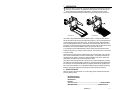
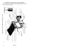
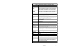
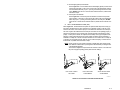
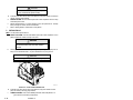
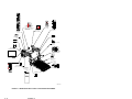
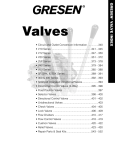
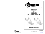
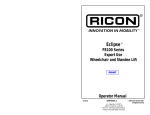
® S-SERIES™AND K-SERIES™ Export Use Wheelchair and Standee Lift with Folding Platform -PRINT- S -S e rie s™ K -S erie s™ Operator Manual 04/12/10 32DSKE01.C -HOME- ® ©2010 RICON CORPORATION All Rights Reserved U.S. Patent Nos: 4,534,450; 5,228,538; 5,308,215; 5,373,915; 5,445,488; 5,605,431; 5,944,473 Australian Patent No: 661127; 687,066 Canadian Patent No: 1,245,603 German and U.K. EP0625896B1 Other U.S. and foreign patents pending. Printed in the United States of America THIS RICON PRODUCT MUST BE INSTALLED BY A RICON DEALER. PRODUCT USERS MUST REFER TO THIS MANUAL FOR OPERATING AND GENERAL MAINTENANCE INSTRUCTIONS. RETAIN THIS MANUAL IN THE VEHICLE FOR FUTURE REFERENCE. This lift may be installed on all vehicles appropriate for the size and weight of the lift, but must be installed in accordance with Ricon’s installation instructions and any statutory and regulatory requirements applicable in the country of use. Customer Information Customer name Installing dealer Date installed Serial number 32DSKE01.C -i- REVISION RECORD REVISION 32DSKE01. C 04-12-10 - ii - PAGES DESCRIPTION OF CHANGE 1-3 Added General Safety Precautions note. 1-4 Updated Figure 1-1. 1-5 Updated Table 1-1. 1-6 Updated Figure 1-2. 1-7 Updated Table 1-2. 2-1 Added Caution. 2-3 Added Safety Precautions. 2-7 Added Safety Alarm Warning System. 32DSKE01.C ECR/ECO 6501 TABLE OF CONTENTS Chapter Page I. INTRODUCTION ........................................................................................................ 1-1 A. PRODUCT SUPPORT ....................................................................................... 1-1 B. PRODUCT WARRANTY .................................................................................... 1-2 C. SHIPMENT INFORMATION ............................................................................... 1-3 D. GENERAL SAFETY PRECAUTIONS ................................................................ 1-3 E. MAJOR LIFT COMPONENTS ............................................................................ 1-4 II. OPERATING INSTRUCTIONS .................................................................................. 2-1 A. SAFETY PRECAUTIONS .................................................................................. 2-1 B. DAILY SAFETY CHECK .................................................................................... 2-3 C. PLATFORM MOTIONS ...................................................................................... 2-4 D. CONTROLS AND INDICATORS ........................................................................ 2-5 • CONTROL PENDANT ................................................................................ 2-5 • LED STATUS INDICATORS, CIRCUIT BREAKERS AND MAIN FUSE ASSEMBLY ................................................................................................ 2-6 • SAFETY ALARM WARNING SYSTEM ...................................................... 2-7 • MANUAL BACK-UP PUMP ........................................................................ 2-8 • LIFT CYCLE COUNTER ............................................................................ 2-8 E. NORMAL LIFT OPERATION ............................................................................. 2-9 1. ENTERING VEHICLE................................................................................. 2-9 2. EXITING VEHICLE ................................................................................... 2-10 3. STOWING PLATFORM ............................................................................ 2-11 F. MANUAL OPERATION .................................................................................... 2-11 1. DEPLOY PLATFORM .............................................................................. 2-11 2. LOWER PLATFORM ................................................................................ 2-13 3. STOW PLATFORM .................................................................................. 2-13 G. EMERGENCY RELEASE SYSTEM (OPTION) ................................................ 2-14 1. DEPLOY PLATFORM .............................................................................. 2-14 2. LOWER PLATFORM ................................................................................ 2-15 3. STOW PLATFORM .................................................................................. 2-15 H. MAINTENANCE AND REPAIR NOTE ............................................................. 2-16 III. MAINTENANCE .............................................................................................. 3-1 A. ADDITIONAL MAINTENANCE INFORMATION ................................................. 3-1 B. CLEANING ......................................................................................................... 3-1 C. MAINTENANCE SCHEDULE ............................................................................. 3-1 D. DECAL PART NUMBERS AND LOCATIONS.................................................... 3-3 32DSKE01.C - iii - This page intentionally left blank. - iv - 32DSKE01.C I. INTRODUCTION T he Ricon S-Series™ and K-Series™ Export Use Wheelchair and Standee lifts provide wheelchair access for road vehicles. The patented movement provides a smooth, safe entry and exit and easily lifts up to 364 kilograms (800 pounds). The platforms on both S- and KSeries™ Export Use Wheelchair lifts have a rated load capacity of 364 kilograms (800 pounds). S -S e rie s™ K -S erie s™ The S-Series™ Export Wheelchair lift has two platforms options. One platform option splits and folds into the vehicle when stowed and the other platform option is a solid, one-piece platform that is raised and folded into the vehicle when stowed. The K-Series™ platform splits horizontally to reduce overall lift height when stowed. This results in a less obstructed view, either into or out of the vehicle. The mechanical linkages provide smooth movement to both non-skid platforms where the wheelchair and occupant are situated during the “Up” and “Down” lift motions. S- and K-Series™ Export Use Wheelchair lifts contain an electro-hydraulic pump with a built-in manual back-up pump and an emergency release (optional). If the lift loses power, it can be raised or lowered manually. Trained personnel or personal users, operate the lift by using a control pendant. The control pendant is used to unfold the platform out from the vehicle (deploy). The passenger boards the nonskid platform and an operator or personal user lowers the platform to the ground. After the passenger departs, the platform may be stowed back into the vehicle. This manual contains warranty information, safety precautions, optional configurations, operating and maintenance instructions that apply to both Ricon S- and K-Series Export Use wheelchair lifts. It is important to user safety that the lift operator be completely familiar with the operating instructions. Once the lift is installed, it is very important that the lift be properly maintained by following the Ricon recommended maintenance and inspection instructions provided in Chapter III. A. PRODUCT SUPPORT If there are questions about this manual, or you need copies, please contact Ricon Product Support at the following location: Vapor Ricon Europe Ltd Littlemoss Business Park Littlemoss Road Droylsden Manchester, M43 7EF .........................................................................................+44 (0)161 3016000 World Wide Website: .............................................................................. www.RiconCorp.com 32DSKE01.C 1-1 B. PRODUCT WARRANTY RICON CORPORATION FIVE-YEAR LIMITED WARRANTY Ricon Corporation (Ricon) warrants to the original purchaser of this product that Ricon will repair or replace, at its option, any parts that fail because of defective material or workmanship as follows: y y y Repair or replace parts for a period of two years from the date of purchase. A complete list of parts covered by this warranty can be obtained from Vapor Ricon Europe. Labor cost for a period of two years from the date of purchase. A Vapor Ricon Europe rate schedule determines parts covered and labor allowed. Repair or replace lift powertrain parts only for a period of five years from date of purchase. A complete list of parts covered can be obtained from Vapor Ricon Europe product support. If You Need to Return a Product: Return this product to Vapor Ricon Europe, following the Vapor Ricon Europe warranty procedure. Please give as much advance notice as possible, and allow a reasonable amount of time for repair. This Warranty Does Not Cover: y Malfunction or damage to product parts caused by accident, misuse, lack of proper maintenance, neglect, improper adjustment, modification, alteration, the mechanical condition of the vehicle, road hazards, overloading, failure to follow operating instructions, or acts of nature (i.e., weather, lightning, flood). Any travel costs associated to effect a repair. NOTE: Ricon recommends that this product be inspected by an authorized Vapor Ricon Europe dealer or qualified service technician at least once every six months or period as defined in the service manual, or sooner if necessary. Required maintenance should be performed at that time. WARNING THIS PRODUCT HAS BEEN DESIGNED AND MANUFACTURED TO EXACT SPECIFICATIONS. ~ ANY MODIFICATION OF THIS PRODUCT CAN BE HAZARDOUS ~ This Warranty is Void If: y y The product has been installed or maintained by someone other than an Vapor Ricon Europe dealer or qualified service technician. The product has been modified or altered in any respect from its original design without written authorization by Vapor Ricon Europe or Ricon Corporation. Ricon disclaims liability for any personal injury or property damage that results from operation of a Ricon product that has been modified from the original Ricon design. No person or company is authorized to change the design of this Ricon product without written authorization by Ricon. Ricon's obligation under this warranty is exclusively limited to the repair or exchange of parts that fail within the applicable warranty period and the authorized labor to accomplish said repair. Ricon assumes no responsibility for expenses or damages, including incidental or consequential damages. Some states do not allow the exclusion or limitation of incidental or consequential damages, so the above limitation or exclusion may not apply. Important: The warranty registration card must be completed and returned to Ricon within 20 days after installation of this Ricon product for the warranty to be valid. The warranty is not transferable. Your statutory rights are not affected by this warranty. 1-2 32DSKE01.C C. SHIPMENT INFORMATION When the product is received, unpack the product and check for freight damage. Claims for damage should be made to the freight carrier immediately. Be sure the installation kit contains all items listed on the kit packing list. Please report any missing items immediately to Ricon Product Support. The warranty and owner registration cards must be completed and returned to Ricon within 20 days to validate the warranty. The sales or service personnel must review the Warranty and Operator Manual with the user to be certain that they understand how to safely operate the product and instruct the user to follow the operating instructions without exception. D. GENERAL SAFETY PRECAUTIONS The following safety precautions apply to both S-Series and K-Series Export Use wheelchair lifts and must be followed during operation and maintenance: Read and thoroughly understand the operating instructions before attempting to operate the lift. Inspect product before each use. If unsafe conditions, unusual noises or movements, do not operate lift until the problem is corrected. Exercise caution when operating lift to avoid injury, and be certain that hands, feet, legs or clothing are not in the path of product movement. Stand clear of doors and platform and keep others clear during operation. The lift requires regular periodic maintenance. A thorough inspection is recommended at least once every six months. The product should be maintained at the highest level of performance. Deploying wheelchair lift onto gravel or loose sand is not recommended. Leaving the wheelchair lift deployed out of vehicle in inclement weather may cause the outer barrier (rollstop) to jam or not work properly. Wheelchair lift is intended for operation on flat level. 32DSKE01.C 1-3 1. R EA R CYCLE COUNTER AUDIBLE ALARM (OPTION) MANUAL BACK-UP PUMP (INSIDE) HYDRAULIC POWER UNIT WITH COVER SERIAL NUMBER SKI ACTUATOR RSM0013001 FRONT ROLLSTOP (OUTER BARRIER) RIGHT PLATFORM SECTION BRIDGEPLATE (INBOARD ROLLSTOP) HANDRAIL HANDRAIL LIGHT (RIGHT) (OPTION) R IG H T VERTICAL ARMS TOP AND BOTTOM ARMS EMERGENCY RELEASE (OPTION) HANDRAIL LEFT PLATFORM SECTION HANDRAIL LIGHT (LEFT) (OPTION) TOGGLE SWITCH (OPTION) LEFT HYDRAULIC CYLINDERS BASEPLATE MINI-FIT CONNECTION CONTROL PENDANT FIGURE 1-1: S-SERIES EXPORT USE WHEELCHAIR LIFT MAJOR COMPONENTS 32DSKE01.C 1-4 MAJOR LIFT COMPONENTS S-SERIES EXPORT USE WHEELCHAIR LIFT MAJOR COMPONENTS E. The major components of the S-Series Export Use wheelchair lift are in Figure 1-1. A description of each of the components is in Table 1-1. TABLE 1-1: S-SERIES EXPORT USE MAJOR COMPONENT TERMS TERM DESCRIPTION Left, right, front, rear Position references when installed lift is viewed from outside of vehicle. Audible alarm (Option) Audible alarm is activated when rollstop is not completely closed or when ski actuator is jammed and requires maintenance or adjustment. Baseplate Bolts to vehicle floor; provides secure foundation for lift structure. Bridgeplate (inboard rollstop) Plate that bridges gap between platform and baseplate when platform is at floor level. Also acts as a rear rollstop when platform is in motion. Control pendant Hand-held device used to control platform motions. Cycle counter Visible at top rear of housing, it records number of times platform has moved from floor to ground and back to floor. Emergency release (Option) Enables emergency release mechanism that opens manual release valve (located on hydraulic pump), disengages stow-lock latch (located on baseplate) then allows platform to lower to ground level. Front rollstop Front barrier prevents wheelchair from inadvertently rolling off of platform during platform movement. Handrail (left and right) Provides handhold for standing passenger. Handrail light (Option) (left and right) Directs light onto platform surface. Hydraulic cylinder (left and right) Telescoping single-acting cylinders convert hydraulic pressure into platform lifting and folding force. Hydraulic power unit Contains hydraulic pump driven by electric motor that produces pressure to raise and fold platform, and a pressure release valve to unfold and lower it. Manual back-up pump handle (located inside housing of hydraulic unit) Used to operate manual back-up pump. Platform Sections (left and right) Component of lift where the wheelchair and occupant are situated during “UP” and “DOWN” lift motions. Serial number Location of lift serial number decal. Ski Actuator and Sensors Each Ski Actuator activates the front rollstop to open and close and are each installed with a sensor. The sensors activate the audible alarm when the front rollstop is not completely closed or ski actuator is jammed and requires maintenance or adjustment. Stow-Lock catch Engages latch located on bottom of bridgeplate when platform is fully stowed. Top and bottom arms (left and right) Upper and lower links that connect vertical arms to baseplate. Toggle Switch (Option) Alternative switch for passenger to raise and lower the platform. Vertical arm (left and right) Connects platform to top and bottom arms. END OF TABLE 32DSKE01.C 1-5 The major components of the K-Series Export Use wheelchair lift are in Figure 1-2. A description of each of the components is in Table 1-2. REAR CYCLE COUNTER AUDIBLE ALARM (OPTION) MANUAL BACK-UP PUMP (INSIDE) HYDRAULIC POWER UNIT WITH COVER LEFT HYDRAULIC CYLINDER BASEPLATE MINI-FIT CONNECTORS CONTROL PENDANT HANDRAIL TOGGLE SWITCH (OPTION) SERIAL NUMBER R IG H T PLATFORM HINGES SKI ACTUATOR FRONT ROLLSTOP FRO NT RSM0013101 FRONT PLATFORM SECTION PLATFORM FOLDING LINKAGE BRIDGEPLATE (INBOARD ROLLSTOP) HANDRAIL VERTICAL ARM TOP AND BOTTOM ARMS EMERGENCY RELEASE (OPTION) REAR PLATFORM SECTION FIGURE 1-2: K-SERIES EXPORT USE WHEELCHAIR LIFT MAJOR COMPONENTS 32DSKE01.C 1-6 K-SERIES EXPORT USE WHEELCHAIR LIFT MAJOR COMPONENTS 2. TABLE 1-2: K-SERIES EXPORT USE MAJOR COMPONENT TERMS TERM DESCRIPTION Left, right, front, rear Position references when installed lift is viewed from outside of vehicle. Audible alarm (Option) Announces when something passes through the threshold area while the lift platform is below floor level. The alarm is activated by threshold beams (optional). Also beeps when ski actuator is jammed or requires maintenance. Bridgeplate (inboard rollstop) Plate that bridges gap between platform and baseplate when platform is at floor level. Also acts as a rear rollstop when platform is in motion. Control pendant Hand-held device used to control platform motions. Cycle counter Visible at top rear of housing, it records number of times platform has moved from floor to ground and back to floor. Emergency release (Option) Enables emergency release mechanism that opens manual release valve (located on hydraulic pump), disengages stow-lock latch (located on baseplate) then allows platform to lower to ground level. Front platform section Front portion of platform that unfolds during deploy and folds during stow. See “Platform folding linkage”. Front rollstop Front barrier prevents wheelchair from inadvertently rolling off of platform during platform movement. Handrail (left and right) Provides handhold for standing passenger. Handrail light (Option) (left and right) Directs light onto platform surface. Hydraulic cylinder (left and right) Telescoping single-acting cylinders convert hydraulic pressure into platform lifting and folding force. Hydraulic power unit Contains hydraulic pump driven by electric motor that produces pressure to raise and fold platform, and a pressure release valve to unfold and lower it. Manual back-up pump handle (located inside housing of hydraulic unit) Used to operate manual back-up pump. Platform folding linkage (left and right) Links that cause front platform section to unfold as it deploys or fold as it stows. Platform hinges Three hinges provide connection between front and rear platform sections. Rear platform section Rear portion of platform that is folded by linkage located within the vertical arms. Serial number Location of lift serial number decal. Ski Actuator and Sensors Each Ski Actuator activates the front rollstop to open and close and are each installed with a sensor. The sensors activate the audible alarm when the front rollstop is not completely closed or ski actuator is jammed and requires maintenance or adjustment. CONTINUED 32DSKE01.C 1-7 TABLE 1-2: K-SERIES EXPORT USE MAJOR COMPONENT TERMS (CONT’D) TERM Stow-Lock catch DESCRIPTION Engages latch located on bottom of bridgeplate when platform is fully stowed. Toggle Switch (Option) Alternative switch for passenger to raise and lower the platform. Top and bottom arms (left and right) Upper and lower links that connect vertical arms to baseplate. Vertical arm (left and right) Connects platform to top and bottom arms. END OF TABLE 1-8 32DSKE01.C II. OPERATING INSTRUCTIONS T his chapter contains safety precautions, daily safety check instructions, control and indicator descriptions, and operating instructions that apply to RICON S-Series™ and K-Series™ Export Use wheelchair lifts. This chapter must be thoroughly understood by the operator before using lift. A. SAFETY PRECAUTIONS The following safety precautions must be complied with at all times when operating lift: Refer to Figure 2-1. Deploying lift when vehicle is on sloped ground is hazardous. Operate lift with vehicle parked on level ground. CAUTION Deploy wheelchair lift platform onto a flat and level ground. Alarm may sound if wheelchair lift is deployed on to gravel, loose sand or uneven ground. RSM0015600 FIGURE 2-1: SLOPED PARKING HAZARD Vehicle must be safely parked with parking brake ON before using lift. Inspect lift before use. Do not use lift if any unsafe condition exists, or unusual noises or movements are noticed, and contact an authorized Ricon dealer or qualified service technician for repair. Read and comply with all warning labels and symbols affixed to wheelchair lift. Refer to Figure 2-2. Wheelchair occupant should preferably face outward on platform when entering or exiting vehicle to minimize the possibility of the large rear wheels rolling up and over the front rollstop. 32DSKE01.C 2-1 RSM0015700 FIGURE 2-2: NEVER ENTER OR EXIT VEHICLE WHILE FACING BACKWARDS ON THE LIFT It is never safe for a wheelchair occupant to exit a vehicle backwards. It is not safe to rely on a threshold-warning device (optional), audible or other, to confirm that it is safe for a passenger to exit backwards. This device may be inoperative or unheard, and they might exit backwards when the platform is on the ground! When exiting vehicle, verify that platform is at same height as floor and front rollstop is up and locked. Do not place equipment or furniture inside vehicle that may prevent pivoting of your wheelchair. Being able to pivot assures that you can safely exit facing outward. Be certain wheelchair fits safely on platform; it must not extend beyond edges or interfere with operation of rollstop. The raised front rollstop prevents slow and unintentional rolling off of the platform. It is not intended to stop a fast-moving wheelchair, which might tip forward if the small front wheels collide with the rollstop. Do not operate with a load in excess of 364 kgs (800 lbs). Keep arms, legs, and clothing away from moving lift parts. The lift is intended for one wheelchair and its occupant (and additionally one assistant dependant upon lift type) or one standee only. Do not overload lift. Refer to Figure 2-3. Do not stand in front of lift while deploying platform. RSM0015800 FIGURE 2-3: STAND CLEAR OF LIFT 2-2 Keep others clear while operating lift. Do not allow an untrained person to operate lift. Careful supervision is necessary if used near children. 32DSKE01.C Do not allow anyone to stand on bridgeplate. A bent bridgeplate can interfere with the platform as it raises and lowers. Lock wheelchair brakes before moving platform (power chair users should turn off power and set brake). Use great care in wet conditions, because the wheelchair brakes are less effective if wheels or platform are wet. Never leave platform outside of vehicle. Return platform to stowed position after use. Do not load an oversize wheelchair into vehicle if it is too large to pivot freely inside vehicle. Deploying wheelchair lift onto gravel or loose sand is not recommended. Leaving the wheelchair lift deployed out of vehicle in inclement weather may cause the outer barrier (rollstop) to jam or not work properly. Wheelchair lift is intended for operation on flat level. Read and understand these safety precautions. Review them periodically and ask other operators to read them as well. Contact an authorized Ricon dealer or qualified service technician or call Ricon Product Support if there are questions. In addition to these recommendations, it may be necessary for additional safety measures to be employed to ensure adequate reduction of risks. It is the responsibility of the operator to ensure that any suitable risk assessments are conducted. B. DAILY SAFETY CHECK Inspect lift before use and meet the following conditions: All functions operate properly. Do not use lift if unusual noises or movements exist, and contact an authorized Ricon dealer or qualified service technician for repair. Vehicle interlock is operating properly. Objects that may interfere with operation are not present. General appearance and lubrication are satisfactory and fasteners are tight. 32DSKE01.C 2-3 C. PLATFORM MOTIONS TABLE 2-1: PLATFORM MOTIONS MOVEMENT S-Series™ DESCRIPTION K-Series™ D E P L O Y Platform unfolds, or deploys, out of vehicle from stowed position to floor level position. If equipped with a power door operator, the doors automatically open before lift deploys. D O W N Platform lowers from vehicle floor level towards ground level. The front rollstop automatically lowers (opens) when platform reaches ground level. U P Platform rises from ground level towards vehicle floor level. The front rollstop automatically rises (closes) when platform leaves ground level. S T O W Platform folds, or stows, from vehicle floor level to the stowed position. If equipped with a power door operator, the doors automatically close after lift stows. END OF TABLE NOTE: The up and down functions do not operate if platform is in stowed position. RSM0015900 FIGURE 2-4: PLATFORM POSITIONS 2-4 32DSKE01.C D. CONTROLS AND INDICATORS WARNING THE LIFT CAN OPERATE ONLY WHEN THE VEHICLE MANUFACTURER INTERLOCK CIRCUITRY IS ACTIVATED. IF NECESSARY, REFER TO VEHICLE OPERATOR MANUAL FOR INTERLOCK INSTRUCTIONS. DO NOT ATTEMPT TO OPERATE LIFT WITH INTERLOCK BYPASSED. CONTROL PENDANT Refer to Figure 2-5. The lift is operated with four push-button switches and an ON-OFF switch located on the hand-held, hard-wired remote-control pendant. Turn on the POWER switch and then press an appropriate push-button switch to control each lift motion. The POWER switch enables the pendant by providing power to it and must be turned on before the lift can be operated. When turned on, the power switch will illuminate. Pressing the DEPLOY push-button switch unfolds the platform from the vehicle, and pressing the STOW push-button switch folds the platform back into the vehicle. Pressing the DOWN push-button switch lowers the platform towards the ground, and pressing the UP push-button switch raises the platform towards the floor. A push-button switch must be held depressed until the motion is completed. Movement of the platform can be halted at any time by releasing the push-button switch. The pendant is typically stowed on a wall-mounted clip inside the vehicle, near the lift. P O W ER EN AB LE S TO W D EP LO Y UP DOWN RSM0013800 FIGURE 2-5: CONTROL PENDANT 32DSKE01.C 2-5 LED STATUS INDICATORS AND MAIN FUSE ASSEMBLY y Pump Solenoid LED Status Indicators Refer to Figure 2-6. The pump has two solenoids that provide a margin of safety if one of them fails with its contacts closed. Green and red LED status indicators monitor the condition of the two solenoids, and are located between two circuit breakers. The green LED is normally off when the pump is not operating and will illuminate when the pump operates. When the pump is not operating and the second solenoid has failed the red LED will illuminate. The green LED will illuminate if the first solenoid has failed. For more information on both indicator lights refer to Service manual 32DSKE02. 8 AMP CIRCUIT BREAKER RESET 30 AMP CIRCUIT BREAKER RESET LED STATUS INDICATOR SOLENOID RSM0013700 FIGURE 2-6: LED STATUS INDICATORS & CIRCUIT BREAKERS y Fuse Assembly Refer to Figure 2-7. The main Fuse assembly is located in the vehicle engine compartment (or as specified by the installer) and is used to interrupt electrical power to the lift electrical system when a major short circuit occurs. In such event, the fuse will rupture and permanently isolate the electrical supply to the lift. Any fault should be identified and rectified prior to replacement of new fuse. Contact a Ricon authorized dealer or qualified service technician for repair. FIGURE 2-7: MAIN FUSE ASSEMBLY 2-6 32DSKE01.C y Handrail Lights (Optional) Circuit Breaker Refer to Figure 2-6. The circuit breaker for the handrail lights (optional) is located on the hydraulic pump assembly. In the event of a short circuit in the handrail lights (optional), the circuit breaker button will “pop-out”. If pressing and releasing button does not reset power, DO NOT press and hold. Contact a Ricon authorized dealer or qualified service technician for repair. y Control System Circuit Breaker Refer to Figure 2-6. The Control System Circuit Breaker is located on the hydraulic pump assembly. In the event of a short circuit in the control system, the circuit breaker button will “pop-out”. If pressing and releasing button does not reset power, DO NOT press and hold. Contact a Ricon authorized dealer or qualified service technician for repair. SAFETY ALARM WARNING SYSTEM (79dB) Refer to Figure 2-8. The wheelchair lift incorporates an optional audible safety alarm warning system which is activated when one of the ski actuators is not operating correctly or if the ski is separated from the actuator. Each actuator employs a microswitch that is attached to each rollstop ski and sends a signal to the audible alarm if the rollstop ski and actuator are not operating properly. If rollstop ski and actuator are in good working order, alarm will not beep and lift will stow or deploy properly. If rollstop ski and actuator are separated, alarm will beep and may prevent platform from deploying or raising which indicates that one or both rollstop ski switches requires adjustment or maintenance. Rollstop ski or actuator will require maintenance if a microswitch fails or if rollstop ski or actuators are not operating correctly, which may cause continuous beeping. Contact a Ricon authorized dealer or qualified service technician for repair. NOTE: Uneven ground may cause continuous beeping of audible safety alarm warning system and is utilized to indicate caution to passenger and attendant before proceeding to board or exit wheelchair lift platform. The maximum A-weighted sound pressure levels located at a distance of one meter from the power unit (typical operating position) will be less than 79dB(A). OPEN OPEN ROLLSTOP CLOSED NO ALARM ROLLSTOP OPEN ALARM BEEPS OPEN SKI/ACTUATOR OPEN ALARM BEEPS RSM0024200 FIGURE 2-8: ROLLSTOP AND ACTUATOR/SKI ALARM POSITIONS 32DSKE01.C 2-7 MANUAL BACK-UP PUMP Refer to Figure 2-9. The manual back-up pump is used to operate the lift if electrical power is not functioning. Controls for the pump are located inside housing of hydraulic unit and consist of a pump handle to raise platform, and a pump pressure release valve to lower it. Instructions for operating manual pump are provided in the “Manual Operation” section later in this chapter. RSM0014000 FIGURE 2-9: MANUAL BACK-UP PUMP & HANDLE LIFT CYCLE COUNTER Refer to Figure 2-10. The cycle counter is located inside the hydraulic pump housing and visible through a slot on the rear side. The counter advances each time the platform moves through a complete cycle, which consists of the platform moving from the vehicle floor to the ground and back to the floor. The number of cycles displayed is used to schedule maintenance operations. For maintenance schedule refer to Chapter III of this document. HYDRAULIC POWER UNIT CYCLE COUNTER RSM0014100 FIGURE 2-10: CYCLE COUNTER 2-8 32DSKE01.C E. NORMAL LIFT OPERATION WARNING IMPROPER USE OF LIFT CAN RESULT IN PERSONAL INJURY. USERS MUST READ AND FOLLOW OPERATING INSTRUCTIONS. ADDITIONAL COPIES OF OPERATOR MANUAL ARE AVAILABLE FROM: VAPOR RICON EUROPE LTD LITTLEMOSS BUSINESS PARK LITTLEMOSS ROAD DROYLSDEN MANCHESTER M437EF DO NOT EXCEED RATED LOAD CAPACITY OF 364 KGS (800 POUNDS) . PRIOR TO USE, INSPECT WHEELCHAIR LIFT FOR PROPER FUNCTION, REQUIRED MAINTENANCE, OR DAMAGE. IF A PROBLEM EXISTS, DO NOT USE LIFT AND CONTACT A RICON AUTHORIZED DEALER OR QUALIFIED SERVICE TECHNICIAN FOR REPAIR. THIS LIFT IS FOR USE BY WHEELCHAIR OCCUPANTS AND STANDEES. RICON CORPORATION DISCLAIMS LIABILITY FOR DAMAGE OR PERSONAL INJURY RESULTING FROM MODIFICATION TO LIFT, LACK OF MAINTENANCE OR REPAIR, NEGLIGENCE, ABUSE, OR FAILURE TO FOLLOW LIFT OPERATING INSTRUCTIONS. Before operating lift, be certain vehicle is safely parked on a level area away from traffic. Provide space for lift operation and passenger boarding. The lift operator must take special care to be certain that area is clear before deploying lift. Be certain there are no obstacles beneath platform. Open doors completely if lift is not equipped with a power door operator. If so equipped, the vehicle doors will automatically open before platform deploys and close after platform is stowed. If equipped with a safety interlock mechanism (e.g. transmission, parking brake, etc) be certain that it is properly engaged before attempting to operate lift. The lift will not operate until this feature has been engaged properly. A person that uses the wheelchair lift while standing (does not require mobility aid equipment) is referred to in this manual as a Standee. WARNING ATTENDANT MUST REMAIN NEAR PASSENGER TO RENDER IMMEDIATE ASSISTANCE WHEN NECESSARY. 1. ENTERING VEHICLE: NOTE: Turn the pendant power switch on. a. b. c. DEPLOY PLATFORM - Push and hold DEPLOY push-button switch until platform is completely unfolded from vehicle and stops at floor level. LOWER PLATFORM - Push and hold DOWN push-button switch until platform is at ground level and front rollstop is fully lowered. Carefully place wheelchair in center of platform, preferably facing outward (away from vehicle), and lock wheelchair brakes. If a power wheelchair is used, turn power off. 32DSKE01.C 2-9 CAUTION Be certain wheelchair is clearly within perimeter of platform and does not interfere with operation of rollstop. Ù d. e. f. 2. A Standee must stand near the center of the platform, facing in the direction of travel (into vehicle), and firmly grasp handrails. RAISE PLATFORM - Push and hold UP push-button switch until platform rises and stops automatically at floor level. Release wheelchair brakes. If a power wheelchair is used, turn power back on. Carefully board passenger into vehicle, and secure wheelchair. Refer to “Stowing Platform” section below to stow platform. EXITING VEHICLE: NOTE: Turn the pendant power switch on. a. DEPLOY PLATFORM - Push and hold DEPLOY push-button switch until platform is completely unfolded from vehicle and stops at floor level. WARNING VERIFY THAT PLATFORM IS AT VEHICLE FLOOR LEVEL AND THAT FRONT ROLLSTOP IS UP AND LOCKED IN POSITION. b. Carefully place wheelchair in center of platform, preferably facing outward (away from vehicle), and lock wheelchair brakes. If a power wheelchair is used, turn power off. CAUTION Do not stand on bridgeplate as platform lowers. Lift damage may occur. RSM0014900 FIGURE 2-11: DO NOT STAND ON BRIDGEPLATE Ù c. 2 - 10 A Standee must stand near the center of the platform, facing in the direction of travel (away from vehicle), and firmly grasp handrails. LOWER PLATFORM - Push and hold DOWN push-button switch until platform is at ground level and front rollstop is fully lowered. 32DSKE01.C d. e. 3. Release wheelchair brakes. If a power wheelchair is used, turn power back on. Carefully assist passenger off platform. Refer to “Stowing Platform” section to stow platform. STOWING PLATFORM: NOTE: If platform is at ground level, push and hold UP push-button switch until platform rises and stops automatically at floor level. a. Push and hold STOW push-button switch until platform folds completely into vehicle. CAUTION Verify that platform has folded completely before closing doors. To avoid damage to doors, do not release switch until lift has folded completely and lift pump motor has stopped automatically. b. F. Close vehicle doors if lift is not equipped with a power door operator. If so equipped, the vehicle doors may close automatically after platform is stowed. MANUAL OPERATION The lift can be operated manually if the lift electrical power source is absent. Ricon recommends that manual operation be used only for exiting passengers from vehicle. Preparation: Be certain vehicle is on a level area and away from traffic. Allow space for platform movement plus space to exit from platform. The vehicle operator must summon assistance to move vehicle to a safe area if a break down situation exists where vehicle cannot be moved under its own power. Open doors manually if vehicle is not equipped with a power door operator. If equipped with a power door operator, refer to its operator manual for manual operation directions. WARNING FOLLOW PRECAUTIONS IN “LIFT OPERATION” SECTION WHEN USING MANUAL BACKUP SYSTEM TO ENTER OR EXIT VEHICLE. NOTE: If unit has an optional Threshold Warning System, it will not active during manual operation and cannot be used to indicate platform height. NOTE: If unit has been equipped with an Emergency Release System (Optional), refer to “Operating Emergency Release System section (Refer to Page 2-13). The following instructions are for units that are not equipped with an Emergency Release System (Optional). 1. DEPLOY PLATFORM a. Refer to Figure 2-12. Override the Stow-Lock feature by lifting bridgeplate by hand. This will separate the Stow-Lock catch (fastened to underside of bridgeplate) from Stow-Lock latch (fastened to baseplate). If Stow-Lock is difficult to separate, use manual backup pump to raise platform slightly to remove tension from catch; refer to “Stowing Platform” paragraph in this section. 32DSKE01.C 2 - 11 RSM0014200 FIGURE 2-12: RAISE BRIDGEPLATE b. Refer to Figure 2-13. Remove hydraulic unit cover to locate pump handle. Insert notched end of pump handle into shaft with roll pin crossing on hydraulic pump unit and engage pump release valve while holding bridgeplate. Once platform starts to deploy, release bridgeplate. CAUTION Do not open pump release valve more than ¼-turn. Opening valve further may cause it to completely disengage from pump body, which will disable its pumping ability. RSM0014300 c. d. FIGURE 2-13: OPEN PRESSURE RELIEF VALVE (CCW) Refer to Figure 2-13. Turn valve 1/4 turn counter-clockwise to begin lowering platform. Refer to Figure 2-14. When platform reaches level of interior floor turn valve clockwise to close; do not over-tighten valve. Do not lower platform below vehicle floor level. The rear edge of bridgeplate must rest flat on vehicle floor. WARNING VERIFY THAT PLATFORM IS AT VEHICLE FLOOR LEVEL AND THAT FRONT ROLLSTOP IS UP AND LOCKED IN POSITION. e. 2 - 12 Load passenger. Carefully place wheelchair in center of platform, facing outward (away from vehicle), and lock wheelchair brakes. If a power wheelchair is used, turn power off. 32DSKE01.C CAUTION Do not stand on bridgeplate as platform lowers. Ù Refer to Figure 2-11. A Standee must stand near the center of the platform, facing in the direction of travel (away from vehicle), and firmly grasp handrails. RSM0014400 FIGURE 2-14: CLOSE PRESSURE RELIEF VALVE (CW) 2. LOWER PLATFORM a. b. c. 3. Refer to Figure 2-13. Turn valve 1/4 turn counter-clockwise to begin lowering platform. Hold valve open until platform settles at ground level. Turn handle clockwise to close valve; do not over-tighten valve. Release wheelchair brakes. If a power wheelchair is used, turn the power back on. Carefully assist passenger off platform. STOW PLATFORM a. b. Refer to Figure 2-14. Verify that pump release valve is closed; do not over-tighten valve. Refer to Figure 2-15. Insert notched end of pump handle into pump shaft with roll pin crossing. Operate pump to begin raising and folding platform. RSM0014500 FIGURE 2-15: PUMP HANDLE TO RAISE PLATFORM 32DSKE01.C 2 - 13 c. d. e. Operate pump until platform is completely folded inside vehicle and Stow-Lock has engaged. Stow pump handle and replace pump cover. Close vehicle doors. G. EMERGENCY RELEASE SYSTEM (OPTION) The Emergency Release System is an option that is available through Ricon. Read and understand the Emergency Release System section before attempting to operate unit. The lift can be operated manually with an Emergency Release System (Optional) if the lift electrical power source is absent. Ricon recommends that use of the Emergency Release System be used only for exiting passengers from vehicle. Preparation: Be certain vehicle is on a level area and away from traffic. Allow space for platform movement plus space to exit from platform. The vehicle operator must summon assistance to move vehicle to a safe area if a break down situation exists where vehicle cannot be moved under its own power. Open doors manually if vehicle is not equipped with a power door operator. If equipped with a power door operator, refer to its operator manual for manual operation directions. WARNING FOLLOW PRECAUTIONS IN “LIFT OPERATION” SECTION WHEN USING MANUAL BACK-UP SYSTEM TO ENTER OR EXIT VEHICLE. NOTE: If unit has an optional Threshold Warning System, it will not active during manual operation and cannot be used to indicate platform height. 1. DEPLOY PLATFORM a. Refer to Figure 2-16. Pulling the yellow emergency release handle will release system pressure and disengage stow-lock device which allows the lift to deploy. NORMAL OPERATING POSITION DEPLOY POSITION HOLD-OPEN POSITION RSM0014600 FIGURE 2-16: EMERGENCY RELEASE HANDLE 2 - 14 32DSKE01.C NOTE: Pull handle far enough to begin deployment and maintain grasp on emergency release handle until platform has reached floor level. Releasing handle during deploy position will halt platform deployment. NOTE: Emergency Release System is equipped to automatically spring handle back to original position and will halt deployment of platform once handle is released from grasp. b. Do not lower platform below vehicle floor level. The rear edge of bridgeplate must rest flat on vehicle floor. WARNING VERIFY THAT PLATFORM IS AT VEHICLE FLOOR LEVEL AND THAT FRONT ROLLSTOP IS UP AND LOCKED IN POSITION. c. Load passenger. Carefully place wheelchair in center of platform, facing outward (away from vehicle), and lock wheelchair brakes. If a power wheelchair is used, turn power off. CAUTION Do not stand on bridgeplate as platform lowers. Ù 2. A Standee must stand near the center of the platform, facing in the direction of travel (away from vehicle), and firmly grasp handrails. LOWER PLATFORM a. Refer to Figure 2-16. Pull and hold emergency release handle until is has reached ground level. NOTE: Pull emergency release handle to the end of its travel to engage emergency release holdopen feature. Emergency release handle will remain in hold-open position until operator disengages hold-open feature by simply pushing handle back to the normal operating (vertical) position. b. Release wheelchair brakes. If a power wheelchair is used, turn the power back on. Carefully assist passenger off platform. 3. STOW PLATFORM a. b. c. d. e. f. Refer to Figure 2-16. Verify that the emergency release handle is in normal operating (vertical) position. Refer to Figure 2-9. Remove hydraulic unit cover to locate pump handle. Insert notched end of pump handle into shaft with roll pin crossing on hydraulic pump unit and engage pump release valve. Turn clockwise to ensure that pump relief valve is closed. Refer to Figure 2-15. Insert notched end of pump handle into pump shaft with roll pin crossing. Operate pump to begin raising and folding platform. Operate pump until platform is completely folded inside vehicle and Stow-Lock has engaged. Stow pump handle and replace pump cover. Close vehicle doors. 32DSKE01.C 2 - 15 H. MAINTENANCE AND REPAIR NOTE Follow the lubrication, cleaning, and maintenance instructions in the following chapter, “Maintenance”. These instructions apply to Ricon S-Series™ and K-Series™ Public Use wheelchair lifts. The instructions are meant to optimize the operating condition of the wheelchair lift. Ricon has performed type and routine testing to demonstrate compliance with the requirements defined in EN 1756-2:2004, for static and dynamic testing as specified in Section 7, Table 2-Verification of the Safety Requirements and/or Measures and as required to be undertaken by the manufacturer defined as “Visual Examination”, “Functional Examination” and “Manufacturers Type Test”. These tests have been conducted and controlled through the Ricon Quality System. The relevant type testing has been recorded under Engineering Test Reports (ETR081011 & ETR206005) and the relevant routine testing is performed in accordance with Routine Test Procedure (FR 824-065_3). Any maintenance and adjustments must be performed by Ricon authorized dealer or qualified service technicians and must comply with these requirements. 2 - 16 32DSKE01.C III. MAINTENANCE T his chapter contains cleaning instructions, a maintenance schedule, and decal information that applies to RICON S-Series™ and K-Series™ Export Use wheelchair lifts. Regular maintenance of the RICON S- and K-Series Export Use wheelchair lifts will provide optimum performance and reduce the need for repairs. A. ADDITIONAL MAINTENANCE INFORMATION Additional maintenance information is available in the RICON S-Series and K-Series Export Use service manual, part number 32DSKE02. This manual is available from Ricon in printed hard copy, or at the Ricon website in PDF format. The website is located at www.RiconCorp.com. At the website, click on “Technical Documents”, “I agree”, and then “Service Manuals”. WARNING THIS RICON PRODUCT IS HIGHLY SPECIALIZED. MAINTENANCE AND REPAIRS MUST BE PERFORMED BY A RICON AUTHORIZED DEALER OR QUALIFIED SERVICE TECHNICIAN USING RICON REPLACEMENT PARTS. MODIFYING OR FAILING TO PROPERLY MAINTAIN THIS PRODUCT WILL VOID THE WARRANTY, AND MAY RESULT IN UNSAFE OPERATING CONDITIONS. B. CLEANING Regular cleaning with mild soap (i.e. liquid hand soap or car wash liquid) and drying thoroughly will protect lift painted surfaces. Cleaning is especially important in areas where roads are salted in winter. Make sure that lift pivot points are clean and dry prior to lubrication. C. MAINTENANCE SCHEDULE Refer to cycle counter located on rear side of hydraulic power unit. Under normal operating conditions, maintenance inspections are required at the frequencies listed in Table 3-1. Ten cycles is considered an average number of cycles for one day. TABLE 3-1: MAINTENANCE SCHEDULE SERVICE POINT ACTION TO PERFORM 10 CYCLES Overall condition Listen for abnormal noises as lift operates (i.e. grinding or binding noises.) Electrical Wiring Inspect electrical wiring for frayed wires, loose connectors, etc. Control pendant Verify that control pendant is undamaged and cable connector is tight. Verify that switch and buttons are illuminated. Safety Alarm Warning Verify that rollstop and ski actuators are working properly. Rollstop and ski actuators System must be properly maintained. 150 CYCLES Overall condition Listen for abnormal noises as lift operates (i.e. grinding or binding noises). Electrical wiring Inspect electrical wiring for frayed wires, loose connectors, etc. Decals Verify that lift decals are properly affixed, clearly visible, and legible. Replace if necessary. Inspect underside of vehicle for anything that is out of place. CONTINUED 32DSKE01.C 3-1 TABLE 3-1: MAINTENANCE SCHEDULE SERVICE POINT ACTION TO PERFORM 150 CYCLES (CONT.) Vehicle interlock Place vehicle in non-interlock mode and verify that lift does not operate. Handrails Lift mounting points Verify that handrail fasteners are properly tightened. Verify that vehicle mounting and support points are undamaged. Verify that mounting bolts are sufficiently tight and corrosion free. Main lifting pivots Platform pivot points Verify that link pins on arms are properly installed, free from damage, and locked in position. Verify that platform moves freely, without binding, and does not wobble. (If applicable) Verify that bridgeplate operates without binding during lift functions. Verify that bridgeplate deploys fully when platform stops at floor level. Verify bridgeplate rests flat against baseplate. Verify that rollstop is opened completely when platform is at ground level. Verify that rollstop closes and locks when platform leaves ground. Verify that cables connected to hydraulic pump are not frayed or binding. Verify that platform fully deploys when emergency release lever is set to full deploy (90° from vertical). If emergency release handle is not set to full deploy (90° from vertical), platform should stop when emergency release handle automatically springs back in position. Bridgeplate Front rollstop Emergency Release (Option) Hydraulic power unit CAUTION Check and add fluid when platform is at fully stowed position. Ensure that the ‘Max’ level mark is not exceeded. Verify that pump hydraulic fluid level is between ‘Min’ and ‘Max’ mark when platform is at fully stowed position. Add Texaco 01554 Aircraft Hydraulic Oil or equivalent U.S. mil spec H5606G fluid. Verify there are no hydraulic fluid leaks. Verify that manual back-up pump operates properly. 1800 CYCLES Cleaning and lubrication 1. Clean lift with mild soap and water and wipe dry. Prevent rust by coating all surfaces with a lightweight oil. Remove excess oil. 2. Spray penetrating oil (Curtisol® Red Grease 88167 or WD-40®) where specified in the service manual 32DSKL02 following directions on container. Remove excess grease from surrounding areas. 3. Verify that the manual release valve is securely tightened. CAUTION A Ricon authorized dealer or qualified service technician must perform the annual safety check. 3600 CYCLES Hydraulic cylinder, hoses and fittings 3-2 Check hydraulic cylinder for evidence of leaks. Inspect hydraulic hoses for damage and verify that all fittings are tight. END OF TABLE 32DSKE01.C D. DECAL PART NUMBERS AND LOCATIONS Inspect decals at intervals in Table 3-1. Inspect for chipping, peeling, fading, and illegibility. Order replacement decals with part number given in Figure 3-1 and Figure 3-2, and apply where shown. Manual Operation 2 2 3 4 1 DE P LO Y A N D DOW N R A IS E A ND S TOW 4209 0 .A M A NUAL O P E R A TIO N C O R P O R A T IO N 7900 N els on R oad , Panora m a C ti y, C A 9140 2 mfg . date: M ade in U .S.A. C O R P O R A T IO N 7900 Ne ls on R oad , P anora ma City , C A 9140 2 mfg. date: M ade in U.S .A. MAX LOAD S-SE RIES LIF T T h is p r od u c t is co v er e d b y o ne or m o re o f th e f oll ow ing pa ten t n o ' s U .S : 4 ,53 4 ,4 5 0 ; 5 ,2 28 , 53 8 ; 5 ,3 0 8 ,2 15 ; 5, 373 ,915 ; 5 ,4 4 5 ,4 88 ; 5, 60 5 ,4 3 1; 5 ,9 44 , 47 3 ; 6 ,043 ,74 1 A us tra li a n : 6 612 7 ; 6 9 706 6 C ana d ian : 1, 245 ,6 03 ; 2, 12 9 ,8 2 1; 2 ,16 8 ,76 1 G e rm an and U .K : EP 0625896 B 1 O th e r U .S . a n d fo re ig n pa t en ts pe n d ing . 350 K g P A R T O F S E R IA L N U M BE R D E C A L (LOCATED ON INNER SIDE OF HYDRAULIC CYLINDER; ONLY RICON REPLACEABLE) 32-10-173.G S -S E R IE S PA T E N T N O . Emergency Release P A R T O F S E R IA L NU M BE R D E C A L (ONLY RICON REPLACEABLE) CLOSED OPEN HOLD-OPEN POSITION DEPLOY AND DOWN 42087.A - M A IN T EN A NC E R E Q U IRE D I F C O N T INU O US LY IL LU M IN ATED - M A IN T E N ANC E D O IT E T RE F A IT E S I CE T T E L U MI ER E RE S T E A LL U M EE E N P E R M A N ENC E E M E RGEN CY R E L E AS E - M A T E N IM IEN T O E S R E Q U ER ID O S I PER M ANEC E C O N T I NU A M E N TE IL U MI NAD O - B E I U NU N T E R BR O CH E NE R W A RN LI C H T ANZE W A R T U N G ER F OR D ER LIC H IGE IST 36932 .A SE C O N D S O L E N O ID 42089 .A P R O PE R LO A D IN G U P CU T OFF A D J U S T M EN T S CRE W D O W N C U T OFF A D J U S T M EN T S CRE W U . S . and f o re ign pa t en ts pend ing . 32-10-171 U S A ND F O R E IG N PA T E N T S PE ND IN G L IM IT S W IT CH E S (INSIDE PUMP COVER) 42079.A NO STANDING ON BRIDGEPLATE (TOP EDGE O F P L A T F O R M ) S TANDEE INSTR UCT IONS S tandee s must stand in center of platform , af cing direc tion of trav el (into or outof vehicle)and firmly gras p han drails. MANUAL OP ERAT ION 1.) See manua l operatingins truc tions andrefer to the Operator M anual. C O NN E C T O R ID CAUTION Keep othe rs clear of w heelc hair liftw hen ope rating. Be certain v ehic el si safely parked before us ing wheelchairlift. M obili ty aid sys tem shou ld bepos itioned incenter of platform s o it does not interferew ti hou ter r olls top ope ration (prev entingit fromlocking). 42092.A (INSIDE PUMP COVER) STA N DEE IN S T RUC T IO N S P RESSUR STAN D EE IN S T RUC T IO N S E S W ITC H P R ESS UR E S W IT C H OIL FILL DECAL ST AND EE MUST R IDE IN C ENTER O F THE PL ATF OR M (IN S ID E P U M P C O V E R ) 42094 .A S /K E X P O R T U S E O P E R A TI N G IN S T RUC T IO N S S/K-SERIES EXPORT USE W H E E L C H A I R & S T A N D E E L I FTS W AR N IN G R IC O N LOG O 1 .) I m p r ope r use o f lift can r esu lt i n p er sona l i n ju ry . U se r m us t r ead and f o ll o w ope r a ti ng i ns truc ti ons i n Ow ne r M anua l. A dd iti ona l cop ie s of Ow ne r M anua l a re ava il ab le fr o m : S T A ND C LEA R C A U TIO N (B O T T O M O F P L A T F O R M ) R I C O N C O R P O RA T IO N 7 9 00 NE L SO N RD. PAN OR AM A CI T Y, CA 9140 2 ( 800 ) 3 22 - 28 8 4 o r (8 1 8) 267 - 300 0 2 .) D o no t exceed r a t ed load . 3 .) P r io r t o use , i nspec t w hee lcha i r lift f or p rope r func ti on , r equ ired m a in tenance , o r da m age . If a p r ob le m ex is t s , do no t use lift. R e t ur n lift t o a n S T A N D C LEA R au t ho ri zed dea le r f o r r epa ir. R ic on Co rpo r a tio n di sc lai ms liabili t y for da m ag e o r pe r s onal inju r y r e sul t ing f r om li ft m odi fica tion , la ck of m ain tenan ce , r epai r, negli gen c e, abu se o r O F M O V I N G P L A TF O R M failu r e t o f ollo w lift ope r a t ing in str uc tion s . OPERATINGINSTRUCTIONS 42091 .A 1 .) Fu lly open doo r s . 2 . ) U se pendan t s w it ch t o app l y po w e r t o pendan t. 3 . ) P r e ss D EP L O Y bu tt on t o un f o ld p la tf o r m to veh icle fl oo r le ve l. 4 .) P r e ss D OW N bu tt on t o l ow e r p la tf o r m t o g r oun d leve l. E NT E R VE H ICL E: 1 .) P lace w hee lcha ir in cen te r o f p la tfo rm , f ac ing ou tw a r d if poss ib le. Lo ck Wh ee l ch a ir b rake s . ( STA N D E E S s e e b e lo w ) . 42 093 .A 2 . ) P r e ss UP bu tt on t o r a ise p la tf o rm t o v eh icle fl oo r leve l. 3 . ) R el ease w hee lcha ir b r akes E X IT V E HI CL E: 1 .) P lace and en t er veh ci le . w hee lcha ir in cen te r o f p la tfo rm , f ac ing ou tw a r d if poss ib le . Lo ck Wh ee l c h a ir b rake s ( STA N D E E S s e e b e lo w ) . 2 . ) P r e ss D OW N bu tt on t o l ow e r p la tf o r m t o g r oun d leve l. 3 . ) R el ease w hee lcha ir b r akes and ex it pla tfo rm . S T O W LI FT: 1 .) P r ess S T O W bu tton t o f o ld p la tf o r m , w h ich w ill sto p au to m a ti ca ll y w hen co m p le tely fo lded . 2 . ) Tu r n pendan t s w itch O FF . 3 . ) C lose d oo r s . S TAN D EES: S tandees m us t s tand i n cen te r o f p latf or m , f ac ing d ir ec ti on o f tr ave l (I n t o o r ou t o f veh ic le), and fir m ly g rasp hand r ail s . M AN UA L O P ERA T IO N S ee M anua M anua l O pe r a ti on i ns tr uc ti o ns in O pe ra to r l o r nea r pu m p cove r . C AU T I ON : K eep o the rs c lea r o f lift w hen ope ra t ing . B e ce rta in veh ic l e i s sa fe ly pa r ked be fo r e us ing lift. W hee lcha ir shou ld be pos iti oned i n cen t e r o f pl a tfo rm so it doe s no t i n te rf e r e w it h ou te r r o lls top ope r a tion (p reven ting it f r o m l ock ing . ) 4 2088 . A RSM0014701 FIGURE 3-1: S-SERIES EXPORT USE LIFT DECAL LOCATIONS AND PART NUMBERS 32DSKE01.C 3-3 Manual Operation 2 2 3 4 1 M AX LO AD 3 5 0Kg DE PL OY Emergency Release A ND D OWN CLOSED OPEN C O R PO R A TI O N 7900 N els on Road , P ano rama City , CA 91402 mf g. da te: HOLD-OPEN POSITION M ade in U .S .A . DEPLOY AND DOWN C O R PO R A TIO N 7900 N elson R oad , P ano ram a City , CA 9140 2 mf g. date: PA R T O F SE R IA L NU M BE R D E C A L (LOCATED ON INNER SIDE OF HYDRAULIC CYLINDER; ONLY RICON REPLACEABLE) R AI SE AN D S TOW 4209 0. A 42087.A Made ni U.S .A. E M E R G ENC Y R E LE AS E P /N 4208 7 P AR T O F S E R IAL NU M BE R D EC AL (ONLY RICON REPLACEABLE) M A N U AL O P E RA TIO N P N 4209 0 420 89.A P R O PE R LO A D ING P /N 4208 9 K-SER IES LIFT T his p ro du ct is c o v e re d by o ne o r m o re o f t he fo llo w in g pa te n t no ' s U .S : 4 ,53 4 ,4 5 0; 5, 228 , 53 8 ; 5 ,3 08 ,2 15 ; 5,373 ,915 ; 5 ,44 5 ,4 88 ; 5 ,60 5 ,4 3 1; 5, 944 , 47 3 ; 6 ,043 ,74 1 A u s tr alia n : 6 61 2 7; 69 7 06 6 U .S . a nd f ore ign pa ten ts pe n ding . C an a dia n : 1 ,2 45 ,60 3 ; 2, 12 9, 821 ; 2 ,168 ,76 1 G e rm an and U .K : EP 0 625896 B1 O th er U .S . an d fo re ig n pa ten ts pend ing . 32-10-171 19518 U S A ND FO R EIG N PA TE N T S PE ND IN G P /N 32 -10 -17 1 K-SE R IE S PA TE N T NO . 19518 - M AI N T E N A N C E R E Q U I R E D I F C O N T IN U OU S LY IL LU M IN A T E D - M AI N T E N A N C E D O IT ET R E F A IT E S I C E TT E LU M IE R E R ES T E A LL U M EE E N PE R M A N E NC E - M A T E N IM I E N T O ES R E Q U ER I D O S I PE R M A N E C E ST AND C LEA R C O N T IN U A M E N T E I LU MI N A D O - BE I UNUN O F M O V IN G P L ATF OR M T E R B R O CH E N E R W A RN LI CH T A N Z EI GE IS T W A R T U N G E R F O R D E R L IC H 36932.A SE C O N D S O LE N O ID P N 3693 2 42099.A S TA ND C LEA R (SQ U A RE ) C A U TIO N P /N 4209 9 U P C U T O FF ADJ UST M ENT S CR EW D O W N C U T OFF ADJ UST M ENT S CR EW LIM IT S W IT C HE S P N 3694 8 (INSIDE PUMP COVER) 42079.A NO STANDING ON BRIDGEPLATE (TOP EDGE O F P L A T F O R M ) P /N 4 2079 ST ANDEE I NS TRUC TIONS S tandees mu st stand in cen ter of platform , fac ni g directio n of trav el(into or out ofveh ic el ) and firmly grasp handrails. MANUA LO PERAT ION 1.) See manu aloperating ni struct oi ns and refer to the Ope rator Manua l. C O NN E C T O R ID C AU T IO N K eep others c el ar of wheelchair lift w hen operating. Be certain vehic le si s af ely parked before us ni g wheelchair lift. M obility aid system s hould be positioned ni center of platform so it do es not interfere wit h outer rollsto p opera tion (preve nting it fromlocking). 42092 .A (INSIDE PUMP COVER) S TA N D EE IN S TRUC TIO N S P /N 4209 2 S T AN D C E N T ER P /N 4209 4 P R E S S UR E S W IT C H 3694 7.A P R ESS UR E SW ITC H P /N 2694 7 (IN SID E P U M P C O VE R ) OIL FILL DECAL STANDEE MUS T RIDE IN CENTER O F T HE PLAT FORM 42094.A S/K EXP O R T US E O PE R AT IN G IN S TRUC TIO N S P /N 4208 8 S/K-SERIES EXPORT USE W H E E LC H A IR & S T AN D E E L I FT S WARNI NG 1 . ) I m proper u s e o f li ft c an re s u lt in per s ona l in jur y . U s er m u s t read O w ner are M anua and f o ll o w oper a ting in s tru c tion s ni l. A dd i tiona l c op ie s o f O w ner M anua l R IC O N L O G O (S Q U A R E) P N 42 09 1 a v a il ab le f ro m : R I C O N C O R PO RA T I O N 7 9 00 N ELS ON RD. P A NO RA M A CITY , C A 9 1402 ( 80 0 ) 3 2 2- 28 8 4 o r ( 8 18 ) 26 7- 3000 2. ) D o no t exc eed ra ted load . 3. ) P r i or t o us e , in s pe c t w hee l cha ir lift f or prope r f un c t ion , requ ired prob m a in t enan c e, or da m age . If a le m e x is t s, do no t u s e li ft. R e turn lift t o a n au thor iz ed dea l er for repa ir . R i con C or po rat ion d isc la im s liab ility fo r da m ag e o r pe r s ona l in ju r y r e su lt ing f ro m lift m odif ica tion , l ack o f m ai nt enan c e , r epa ir , n eg ligenc e, abus e o r f a ilu r e t o f oll o w lift ope r a ting ins tr uc tion s. OPERATING INSTRUCTIONS 42091.A 1 .) F u lly op en door s . 2. ) U s e pendan t s w i tc h t o app ly po w er t o pendan t . 3. ) P re ss DEP LO Y bu tt on t o un f ol d p la tf or m to v ehic le floor le v e l. 4. ) P re ss DO W N bu tt on t o lo w er p la tf or m to groun d le v e l. E NT E R VE HI CL E: 1 .) P la c e w hee lc ha ir in c en t er of pla tfor m , f ac ing ou t w ard i f p oss ible . (S T A ND EES Lo ck W h ee lc ha ir b rake s . se e be low ). 2. ) P re ss UP bu tt on t o ra i s e p la tf or m t o v eh icle floo r le v e l. 3. ) R e lea se w hee lc ha i r bra k e s and en ter v eh ic le . EX I T VE H ICL E: 1 .) P la c e w hee lc ha ir in c en t er of pla tfor m , f ac ing ou tw ard if p oss ib le. (S T A ND EES Lo ck W h ee lc ha ir b rake s se e be low ). 2. ) P re ss DO W N bu tt on t o lo w er p la tf or m to groun d le v e l. 3. ) R e lea se w hee lc ha i r bra k e s and ex it p latf or m . ST O W LI FT: 1 .) P re ss S T O W bu tt on t o f ol d p latf or m , w hic h w ill st op au t o m a tic a lly w hen 2. ) T urn pendan c o m p lete ly f olded . t s w itc h O FF . 3. ) C l os e door s . ST AND EES : S t andee s m u s t s tand in c en te r o f pla tfor m , f a c ing di re c t ion o f t ra v e l ( I n to or ou t of veh ic le) , and f irm ly gra s p han dra il s. M ANUA L O PE RA T IO N S ee M anua l O pera M anua l or near tion in s t ru c t oi n s in Opera t or pu m p cov er . CAU TIO N: K eep ot her s c lear o f lift w hen o pera ting . B e c er ta in veh ic le is s a fe ly par k ed be f or e u s ing li ft. W hee lc ha ir shou ld be po s it ioned no t in t er f ere i n c en t er o f p latf or m s o it doe s w i th ou t er ro ll s top opera tion (pre v en ting i t f ro m l oc k i ng .) 42088 . A RSM0014801 FIGURE 3-2: K-SERIES EXPORT USE LIFT DECAL LOCATIONS AND PART NUMBERS 3-4 32DSKE01.C