1
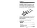
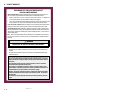
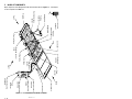
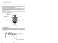
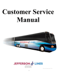
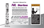
® MIRAGE F9TF MOTORCOACH DOT - PUBLIC USE LIFT PRINT OPERATOR MANUAL 12/23/04 ® 32DF9T15.A 95-2004 RICON CORPORATION All Rights Reserved U.S. Patent Nos. 5,228,538; 5,253,973; 5,373,915; 5,556,250; Australian Patent Nos. 661127, 680501; Canadian Patent No. 2,129,821; French Patent No. 0-446-224; German Patent Nos. 68925368.0-08, EP 0625896 B1; U.K. Patent Nos. EP 0625896 B1, EP 0703766, GB 2,224,992 B; Other U.S. and foreign patents pending. Printed in the United States of America This RICON product must be installed and serviced by authorized RICON service technicians. The operator must refer to this manual for operating instructions, then retain it for future reference by authorized RICON service technicians who perform service and repair. “DOT – Public Use Lift” verifies that this platform lift meets the public use lift requirements of FMVSS no. 403. This lift may be installed on all vehicles appropriate for the size and weight of the lift, but must be installed on buses, school buses, and multi-purpose passenger vehicles other than motor homes with a gross vehicle weight rating (GVWR) that exceeds 10,000 lbs (4,536 kgs). Customer Information Customer name Installing dealer Date installed Serial number 32DF9T15.A i REVISION RECORD REV PAGES 32DF9T15. A All DESCRIPTION OF CHANGE New release. NA END OF TABLE ii ECR/ ECO 32DF9T15.A CHAPTER I. TABLE OF CONTENTS PAGE INTRODUCTION .......................................................................................1-1 A. PRODUCT SUPPORT .............................................................................1-1 B. PRODUCT WARRANTY ..........................................................................1-2 C. SHIPMENT INFORMATION ....................................................................1-3 D. GENERAL SAFETY PRECAUTIONS..........................................................1-3 E. MAJOR LIFT COMPONENTS...................................................................1-4 II. OPERATING INSTRUCTIONS....................................................................2-1 A. B. C. D. E. III. A. B. C. SAFETY PRECAUTIONS .........................................................................2-1 PRE-OPERATION LIFT INSPECTION........................................................2-2 PLATFORM MOTIONS............................................................................2-3 CONTROLS AND INDICATORS ...............................................................2-4 LIFT OPERATION ...................................................................................2-7 1. NORMAL LIFT OPERATION ................................................................2-8 a. To Enter Vehicle .........................................................................2-8 b. To Exit Vehicle............................................................................2-8 2. MANUAL LIFT OPERATION ..............................................................2-10 a. Manual Lift Controls .................................................................2-10 b. Manually Deploy Platform .........................................................2-11 c. Manually Raise Platform ...........................................................2-12 d. Manually Lower Platform ..........................................................2-13 e. Manually Stow Platform............................................................2-14 MAINTENANCE .......................................................................................3-1 ADDITIONAL MAINTENANCE INFORMATION...........................................3-1 DRIVER CHECKLIST ..............................................................................3-1 DECAL MAINTENANCE ..........................................................................3-1 32DF9T15.A iii -RETURN TO FRONT COVER- -GO TO NEXT CHAPTER- This page intentionally left blank. iv 32DF9T15.A I. INTRODUCTION Safe and easy access to motorcoaches is provided by the Ricon Mirage F9TF Public Use wheelchair and standee lift. The Mirage F9TF is a dedicated entry model, which is intended for installation in a vehicle baggage compartment, or similar location. An electric-motor driven hydraulic pump provides a maximum platform lifting capacity of 660 pounds (300 kilograms). A trained attendant or the vehicle operator operates it. For a boarding passenger, the operator uses control switches to withdraw the platform from the vehicle (deploy) and lower it to ground level. The passenger is placed on the platform and then lifted to floor height. After the passenger enters the vehicle, the operator lowers the platform and retracts it back into the vehicle (stow). For an exiting passenger, the operator withdraws the platform from the vehicle (deploy) and raises it to floor height. The passenger is placed on the platform and then lowered to the ground. The passenger departs, and the operator returns the platform to the stowed position in the vehicle. One individual can manually operate the lift when normal power is not present. A manual release mechanism is provided to ease the task of pulling the platform out of its enclosure. The hydraulic pump assembly includes a manually operated back-up pump to raise the platform, and a pressure release valve to lower it. The front platform rollstop, normally power operated, has a manual override knob for back-up use. This manual contains complete operating instructions for the lift, and a brief maintenance chapter. It is important to passenger safety that the lift operator be familiar with the Operating Instructions chapter. It is also important to properly maintain the lift by following the recommended cleaning, lubrication, and inspection directions in the Maintenance chapter. A. PRODUCT SUPPORT Please contact Ricon Product Support if you have questions about this manual, or need additional copies: Ricon Corporation 7900 Nelson Road Panorama City, CA 91402........................................................................................(818) 267-3000 Outside (818) Area Code...........................................................................................(800) 322-2884 World Wide Website ..........................................................................................www.riconcorp.com Littlemoss Business Park, Littlemoss Road Droylsden, Manchester United Kingdom, M43 7EF............................................................................... (+44) 161 301 6000 32DF9T15.A 1-1 B. PRODUCT WARRANTY RICON MIRAGE F9TF PUBLIC USE WHEELCHAIR LIFT TWO-YEAR LIMITED WARRANTY Ricon Corporation (Ricon) warrants to original purchaser of this product that Ricon will repair or replace, at its option, any part that fails due to defective material or workmanship as follows: • Repair or replace parts for a period of two-years from the date of purchase. A complete list of parts covered by this warranty can be obtained from Ricon Product Support. • Labor costs for specified parts replaced under this warranty for a period of two-years from the date the lift is put into service. A Ricon rate schedule determines parts covered and labor allowed. If you need to return a product: Return this product to Ricon, following the Ricon RMA procedure. Please give as much advance notice as possible, and allow a reasonable amount of time for repair. This warranty does not cover: Malfunction or damage to product parts caused by accident, misuse, lack of proper maintenance, neglect, improper adjustment, modification, alteration, the mechanical condition of vehicle, road hazards, overloading, failure to follow operating instructions, or acts of nature (i.e., weather, lightning, flood). Note: Ricon recommends that this product be inspected by a Ricon authorized service technician at least once every six months, or sooner if necessary. Any required maintenance should be performed at that time. WARNING THIS PRODUCT HAS BEEN DESIGNED AND MANUFACTURED TO EXACT SPECIFICATIONS. MODIFICATION OF THIS PRODUCT IN ANY RESPECT CAN BE HAZARDOUS. This warranty is void if: • The product has been installed or maintained by someone other than a Ricon authorized service technician. • The product has been modified or altered in any respect from its original design without written authorization by Ricon. Ricon disclaims liability for any personal injury or property damage that results from operation of a Ricon product that has been modified from the original Ricon design. No person or company is authorized to change the design of this Ricon product without written authorization by Ricon. Ricon's obligation under this warranty is exclusively limited to the repair or exchange of parts that fail within the applicable warranty period. Ricon assumes no responsibility for expenses or damages, including incidental or consequential damages. Some states do not allow the exclusion or limitation of incidental or consequential damages, so the above limitation or exclusion may not apply. Important: The warranty registration card must be completed and returned to Ricon within 20 days after installation of this Ricon product for the warranty to be valid. The warranty is not transferable. The warranty gives specific legal rights, and there may be other rights that vary from state to state. 1-2 32DF9T15.A C. SHIPMENT INFORMATION When the product is received, unpack the product and check for freight damage. Claims for any damage should be made to the carrier immediately. Be sure the installation kit contains all items listed on the kit packing list. Please report any missing items immediately to Ricon Product Support. The warranty and owner registration cards must be completed and returned to Ricon within 20 days to validate the warranty. D. GENERAL SAFETY PRECAUTIONS CAUTION The sales or service personnel must review the Warranty and Operator Manual with the user to be certain that they understand how to safely operate the product. Instruct the user to follow the operating instructions without exception. The following general safety precautions must be followed during installation, operation, service, and maintenance: To avoid injury, always exercise caution when operating and be certain that hands, feet, legs, and clothing are not in the path of product movement. Read and thoroughly understand the operating instructions before attempting to operate. Inspect the product before each use. If an unsafe condition, unusual noises or movements exist, do not use it until the problem is corrected. Stand clear of doors and platform and keep others clear during operation. The product requires regular periodic maintenance. A thorough inspection is recommended at least once every six months. The product should be maintained at the highest level of performance. 32DF9T15.A 1-3 ON STOW POWER DOWN OFF UP Control pendant Platform release shaft Bridgeplate Hydraulic cylinder Deployment system Carriage Lifting frame Rollstop control knob Controller Left Front rollstop Cycle counter Rear Enclosure Pull box Electric circuit breakers Manual pump handle Hydraulic pump assembly Fluid reservoir FIGURE 1-1: LIFT COMPONENTS FOR MIRAGE F9TF MODEL DEPLOY Safety belt Folding handrail Handrail release button Platform Front Right Hydraulic pump enclosure 32DF9T15.A 1-4 MAJOR LIFT COMPONENTS E. Major components of the Mirage F9TF Public Use wheelchair lift are in Figure 1-1. A description of each component is in Table 1-1. TABLE 1-1: LIFT TERMS FOR F9TF PUBLIC USE MODEL TERM DESCRIPTION Left, Right, Front, Rear Reference points from outside vehicle looking inward at lift. Hydraulic pump enclosure Contains lift hydraulic and electrical control components. Also houses manual backup pump handle. Electric circuit breakers Prevent high-current damage to electrical control components. Do not protect hydraulic pump motor. Hydraulic pump assy Electro-hydraulic unit provides hydraulic pressure used to raise platform. Also mounts components for manual operation. Manual pump handle Used to manually operate hydraulic backup pump and pressure release valve when electrical power is not available. Also used to rotate platform release shafts. Pull box Houses electrical termination points to lift, and a hydraulic line disconnect point. Also accepts input harness from control pendant. Control pendant Hand-held device used to control platform motions. Carriage Part of traveling frame that is mounted on rollers; moves on rails located inside enclosure. Supports lifting frame and platform. Cycle counter Located on rear frame of carriage. Visible when platform is fully deployed. It records number of times platform has moved from floor to ground and back to floor. Deployment system Located within carriage. Employs an electric gear-motor to propel platform out of enclosure, or pull it back into enclosure. Hydraulic cylinder Located within carriage and connected to lifting frame. Receives pressurized fluid from hydraulic pump to lift platform. Platform release shaft (left and right) Used during manual operation of lift. Disengages platform from enclosure to facilitate manual deployment. Engage and rotate either shaft with manual pump handle. Fluid reservoir Container holds hydraulic fluid that is used by hydraulic system. Lifting frame Assembly is hinged to front of carriage and to center of platform; raised by single hydraulic cylinder attached to carriage. Rollstop control knob Provides manual control of rollstop if electrical power is not available. Front rollstop Front barrier prevents wheelchair from inadvertently rolling off platform during platform movement. Platform Curbed area where passenger resides while being raised to vehicle or lowered to ground. Safety belt Safety restraint belt that spans between handrails to help confine passenger to platform area. Folding handrail (left and right) Provides a handhold for standing passenger (standee). 32DF9T15.A 1-5 TABLE 1-1: LIFT TERMS FOR F9TF PUBLIC USE MODEL TERM DESCRIPTION Bridgeplate Plate bridges gap between platform and vehicle floor when platform is at floor level. Acts as barrier during up and down platform motions to prevent wheelchair from rolling off rear of platform. Enclosure Platform housing that is rigidly attached to vehicle chassis. Controller Receives electrical input signals from pendant and lift sensors and sends control signals to lift electrical and hydraulic components. Travelling frame (not shown as unit) Assembly comprised of carriage, lifting frame, and platform. END OF TABLE -RETURN TO TABLE OF CONTENTS- 1-6 32DF9T15.A -GO TO NEXT CHAPTER- II. OPERATING INSTRUCTIONS T his chapter contains safety precautions, a daily safety check, a description of lift functions, control and indicator descriptions, plus individual operating instructions for the Ricon Mirage F9TF Public Use wheelchair and standee lift. This chapter must be thoroughly understood by the operator. A. SAFETY PRECAUTIONS The following safety precautions must be complied with at all times when operating lift: Refer to Figure 2-1. Operate lift with vehicle parked on level ground. Deploying lift when vehicle is on sloped ground is hazardous. FIGURE 2-1: VEHICLE INCLINED DUE TO SLOPE Vehicle must be safely parked with parking brake on before using lift. Inspect lift before use. Do not use lift if an unsafe condition exists, or if unusual noise or movement is noticed. Contact a Ricon authorized service technician for repair. Read and comply with all warning labels and symbols affixed to wheelchair lift. Wheelchair occupant should face outward when entering or exiting vehicle. Do not back onto platform when exiting vehicle. Face outward, if possible, and verify that platform is at the same height as floor. Check that front rollstop is up and locked. The front rollstop is intended to prevent slow, unintentional, rolling off of platform. The front rollstop is not intended to stop a quick moving wheelchair. A quick moving wheelchair could tip if the small front wheels collide with the rollstop. Also, the large rear wheels of a quick moving wheelchair could roll over the rollstop. Possible injury to the occupant might occur in either case. Verify that wheelchair fits safely on platform; it must not extend beyond edges or interfere with operation of rollstop. Do not operate with a load in excess of 660 lbs (300 kg). Keep arms, legs, and clothing away from moving lift parts. The lift is intended for one wheelchair and its occupant, or one standee. Do not overload lift. Keep others clear while operating lift. Do not allow an untrained person to operate lift. 32DF9T15.A 2-1 Do not allow anyone to stand on bridgeplate. A bent bridgeplate can interfere with the platform as it raises and lowers. Lock wheelchair brakes before raising or lowering platform (power chair users should turn off power and set brake). Use great care in wet conditions; the wheelchair brakes are less effective if its tires or the platform are wet. Do not leave deployed platform unattended. Return to stowed position after use. Read and understand the preceding safety precautions. Review them periodically and ask attendants or other operators to read them as well. Contact a Ricon authorized service technician or call Ricon Product Support if there are questions. B. PRE-OPERATION LIFT INSPECTION Refer to the “Driver Checklist” section in Chapter 3. Ricon recommends that the listed inspection points be performed each time the vehicle is put into service, or when a driver change occurs during a work-shift. This inspection can be part of the normal pre-use walk-through done by the vehicle operator. 2-2 32DF9T15.A C. PLATFORM MOTIONS Refer to Table 2-1 and Figure 2-2. The table describes the four platform motions, and the figure shows the four typical platform heights plus the stow position. TABLE 2-1: PLATFORM MOTIONS MOTION DESCRIPTION OUT Platform extends out of vehicle, or deploys. Platform lowers from present height towards ground; front rollstop DOWN * lowers when platform contacts ground. UP * IN Platform rises from present height towards vehicle floor; rollstop rises before platform leaves ground. Platform retracts into vehicle, or stows. END OF TABLE * The UP and DOWN motions operate only when platform is fully deployed. NOTE: HANDRAILS OMITTED FOR CLARITY. FLOOR HEIGHT STOWED POSITION INTERMEDIATE HEIGHT DEPLOYED POSITION GROUND LEVEL FIGURE 2-2: PLATFORM POSITIONS 32DF9T15.A 2-3 D. CONTROLS AND INDICATORS Control Pendant Refer to Figure 2-3. The lift is operated with a hand-held, hard-wired remote-control pendant. Turn on the POWER ENABLE switch and then control each lift motion by pressing an appropriate button. The POWER ENABLE switch provides power to the pendant and thereby enables the lift. When turned on, the power switch and each button illuminate. Pressing the DEPLOY button extends the platform from the lift storage compartment, and pressing the STOW button retracts the platform back into the storage compartment. Pressing the DOWN button lowers the platform towards the ground, and pressing the UP button raises the platform towards the vehicle floor. A button must be held depressed until the motion is completed. Movement of the platform can be halted at any time by releasing the button. POWER ENABLE POWER OFF ON STOW DEPLOY DEPLOY STOW UP DOWN UP DOWN FIGURE 2-3: CONTROL PENDANT Electric Circuit Breakers Refer to Figure 2-4. The circuit breakers shown interrupt electric power to specific sections of the lift if a malfunction causes an abnormally high current flow. The Control System and In/Out Motor circuit breakers are mounted on a common bracket, which is located at the top of the hydraulic pump enclosure. IN/OUT MOTOR CIRCUIT BREAKER CONTROL SYSTEM CIRCUIT BREAKER 2-4 FIGURE 2-4: LIFT CIRCUIT BREAKERS 32DF9T15.A Control System Circuit Breaker Refer to Figure 2-4. The five-amp control system circuit breaker is in the pump box. The circuit breaker button will “pop-out” when a control system short circuit occurs. Press button to reset. Do not press button and hold it if pressing and releasing does not restore power. Contact a Ricon authorized service technician for repair. In/Out Motor Circuit Breaker Refer to Figure 2-4. The 30 amp In/Out motor circuit breaker is also in the pump box. The circuit breaker button will “pop-out” when a short circuit occurs in the motor circuit that extends and retracts the platform. Press button to reset. Do not press button and hold it if pressing and releasing does not restore power. Contact a Ricon authorized service technician for repair. Main Lift Circuit Breaker Refer to Figure 2-5. The main circuit breaker is mounted in the vehicle engine or battery compartments, and will interrupt electrical power if a major short circuit occurs, particularly in the hydraulic pump motor circuit. The reset tab rotates clockwise when a short occurs. Rotate the reset tab counter-clockwise to reset breaker (as shown). Do not rotate tab and hold it if rotating and releasing does not restore power. Contact a Ricon authorized service technician for repair. RESET TAB FIGURE 2-5: MAIN CIRCUIT BREAKER – SHOWN RESET Vehicle Interlock System The purpose of the vehicle interlock system is to prevent lift operation if it is unsafe to do so. Typical requirements are that the vehicle transmission be in neutral, the parking brake be applied, and the passenger door be opened before power is supplied to the lift. Before the vehicle can depart, the lift must be stowed, and both the lift compartment door and passenger door must be closed. Bridgeplate Load Sensor A sensor switch is located in the hydraulic line connected to the bridgeplate hydraulic cylinder. When the sensor detects that an object is present on the bridgeplate it inhibits raising or lowering of the platform. This protects the passenger from possible injury when the cylinder raises the bridgeplate. It also protects the bridgeplate from damage, which could interfere later with proper operation of the lift. 32DF9T15.A 2-5 Lift Cycle Counter Refer to Figure 1-1 in Chapter I. The cycle counter is mounted inside the carriage, on the rear frame member, just to the right of the hydraulic cylinder. The platform must be fully deployed to view the counter. The counter advances each time the platform moves through a complete cycle, which consists of the platform moving from the vehicle floor to the ground and back to the floor. The number of cycles displayed is used to schedule maintenance operations. Threshold Warning System Refer to Figure 2-6. The threshold warning system is installed at the top of the doorway above the lift compartment. The module is turned on when the lift is powered, and the status indicator will then light. The acoustic sensors are enabled when the door is open and the lift-vehicle interlock system requirements are met. Acoustic sensors (transmitter and receiver) monitor the doorway threshold area for the presence of a passenger (or object, such as a wheelchair). If someone is detected in the threshold area when the platform is one inch, or more, below the floor an audible buzzer and flashing red light are actuated. This system provides a margin of safety for lift passengers by warning them when the platform is below floor level. The platform must be at floor level when a passenger is boarding or exiting the platform. NOTE: An optional installation method can disable the buzzer and flashing light when the door is closed. In this case, the status indicator flashes when the presence of a passenger is detected. STATUS INDICATOR BUZZER FLASHING LIGHT ACOUSTIC SENSORS FIGURE 2-6: THRESHOLD WARNING SYSTEM MODULE (VIEWED FROM INTERIOR OF VEHICLE) 2-6 32DF9T15.A E. LIFT OPERATION WARNING IMPROPER USE OF LIFT CAN RESULT IN PERSONAL INJURY. USERS MUST READ AND FOLLOW OPERATING INSTRUCTIONS IN THIS MANUAL. ADDITIONAL COPIES OF THE OPERATOR MANUAL ARE AVAILABLE FROM: RICON CORPORATION 7900 NELSON ROAD PANORAMA CITY, CA 91402 (818) 267-3000 or (800) 322-2884 DO NOT EXCEED RATED LOAD CAPACITY OF 660 POUNDS (300 KG). INSPECT WHEELCHAIR LIFT FOR PROPER FUNCTION, REQUIRED MAINTENANCE, AND DAMAGE PRIOR TO USE. DO NOT USE LIFT IF A PROBLEM EXISTS, AND CONTACT AN AUTHORIZED RICON SERVICE TECHNICIAN FOR REPAIR. THIS LIFT IS TO BE USED BY ONE WHEELCHAIR OCCUPANT OR ONE STANDEE, ONLY. RICON CORPORATION DISCLAIMS LIABILITY FOR DAMAGE OR PERSONAL INJURY RESULTING FROM MODIFICATION TO THE LIFT, LACK OF MAINTENANCE OR REPAIR, NEGLIGENCE, ABUSE, OR FAILURE TO FOLLOW THE OPERATING INSTRUCTIONS. Before operating lift, be certain vehicle is safely parked on a level area away from traffic. Provide space for lift operation and passenger boarding. The lift operator must take special care to ensure that area is clear before deploying platform. Be certain there are no obstacles beneath platform. Open lift compartment doors completely and secure. Open passenger entry door directly above lift compartment. This does not apply to models that stop upward platform movement prior to reaching floor level. The entry door on these models is opened after the platform reaches intermediate height (refer to Figure 2-2). If the vehicle and lift are equipped with a safety interlock system (e.g. transmission, parking brake, etc) be certain that it is in the proper mode before attempting to operate lift. The lift will not operate until this feature has been properly engaged. Turn on lift power switch located on or near vehicle dashboard, if so equipped. Enable lift control pendant by turning on Power switch located on pendant. A person that uses the wheelchair lift while standing (does not require mobility aid equipment) is referred to in this manual as a Standee. WARNING THE ATTENDANT MUST REMAIN NEAR LIFT PASSENGER TO PROVIDE ASSISTANCE, IF NECESSARY. WARNING THE LIFT CAN ONLY BE OPERATED WHEN ENABLED BY THE VEHICLE INTERLOCK CIRCUITRY. DO NOT BYPASS THE INTERLOCK TO OPERATE LIFT. REFER TO VEHICLE SERVICE MANUAL FOR INTERLOCK INFORMATION BEFORE OPERATING LIFT. WARNING CAUTION PASSENGERS TO STAY CLEAR OF PASSENGER ENTRY DOOR WHILE IT IS OPENED. 32DF9T15.A 2-7 1. NORMAL LIFT OPERATION a. To Enter Vehicle: 1) ACTIVATE INTERLOCK: Refer to vehicle manufacturers operator manual to enable vehicle interlocks; i.e. set parking brake, place transmission in neutral, etc. 2) DEPLOY PLATFORM: Press and hold OUT button until platform is fully deployed. NOTE: Platform cannot be moved up or down unless platform is fully extended. 3) RAISE HANDRAILS: Lift right handrail to vertical and push firmly down into its socket. Repeat for left handrail. Verify that both handrails are latched in place by attempting to pull upward on them. 4) LOWER PLATFORM: Press and hold DOWN button until platform stops at ground level and rollstop opens completely. 5) BOARD PLATFORM: Position wheelchair in center of platform, facing outward if possible, and advise occupant to lock wheelchair brakes. Power should be turned off on electric-powered wheelchairs. Standee must stand near the center of the platform, facing in the direction of travel (into vehicle), and firmly grasp handrails. Do not stand on bridgeplate. 6) BUCKLE SAFETY BELT. Pull safety belt from retractor on left handrail and fasten to other handrail. NOTE: The next two steps apply only to F9TF models that stop upward platform movement at an intermediate level (refer to Figure 2-2). Other models continue at step 9. 7) PARTIALLY RAISE PLATFORM: Press and hold UP button until platform stops at intermediate height. 8) OPEN VEHICLE DOOR: Fully open vehicle sliding door located above lift. The lift operator, or attendant should do this. 9) RAISE PLATFORM: Press and hold UP button until platform stops at floor height and bridgeplate lowers onto vehicle floor. CAUTION Verify that rear edge of bridgeplate lies flat on floor along its entire edge and does not create a tripping hazard. 10) EXIT PLATFORM: Advise passenger to carefully enter vehicle. 11) UNBUCKLE SAFETY BELT. 12) LOWER HANDRAILS: Press release button at base of handrail and lift the left handrail upward out of its socket. Lower handrail to platform. Repeat for right handrail. 13) STOW PLATFORM: Press and hold IN button until platform reaches STOW height and then fully retracts into vehicle. NOTE: Do not use DOWN button to lower platform partway prior to stowing, and then complete the stowing process by using IN button. This method may not properly stow platform. b. To Exit Vehicle: 1) 2) 2-8 DEPLOY PLATFORM: Press and hold OUT button until platform is fully deployed. RAISE HANDRAILS: Lift right handrail to vertical and push firmly down into its socket. Repeat for left handrail. Verify that both handrails are latched in place by attempting to pull upward on them. 32DF9T15.A 3) BUCKLE SAFETY BELT. Pull safety belt from retractor on left handrail and fasten to other handrail. NOTE: The next two steps apply only to F9TF models that stop upward platform movement at an intermediate level (refer to Figure 2-2). Other models continue at step 6. 4) PARTIALLY RAISE PLATFORM: Press and hold UP button until platform stops at intermediate height. 5) OPEN VEHICLE DOOR: Fully open vehicle sliding door located above lift. The lift operator, or attendant should do this. 6) RAISE PLATFORM: Press and hold UP button until platform stops at floor height and bridgeplate lowers onto vehicle floor. CAUTION Verify that rear edge of bridgeplate lies flat on floor along its entire edge and does not create a tripping hazard. 7) BOARD PLATFORM: Position wheelchair in center of platform, facing outward if possible, and advise occupant to lock wheelchair brakes. Power should be turned off on electric-powered wheelchairs. Standee must stand near the center of the platform, facing in the direction of travel (out of vehicle), and firmly grasp handrails. Do not stand on bridgeplate. 8) LOWER PLATFORM: Press and hold DOWN button until platform stops at ground level and rollstop opens completely. 9) UNBUCKLE SAFETY BELT. 10) EXIT PLATFORM: Carefully assist passenger off of platform. 11) LOWER HANDRAILS: Press release button at base of handrail and lift the left handrail upward out of its socket. Lower handrail to platform. Repeat for right handrail. 12) STOW PLATFORM: Press and hold IN button until platform reaches STOW height and then fully retracts into vehicle. 32DF9T15.A 2-9 2. MANUAL LIFT OPERATION The lift can be operated manually if it loses electrical power. The following sections describe the lift controls associated with manual operation, important safety preparations to be followed before using the lift, and operating procedures to deploy, raise, lower, and stow the lift. Ricon recommends that manual operation be used only to exit from vehicle, not to enter vehicle. a. Manual Lift Controls Manual operation components used are a hydraulic backup pump, platform release mechanism, and a rollstop control knob. Hydraulic Backup Pump Refer to Figure 2-7. The manual back -up pump is part of the hydraulic pump assembly, and is operated with a separate pump handle. Pumping the handle raises the platform when the release valve is closed. A pump pressure release valve for bleeding pressure from the hydraulic system is also on the hydraulic pump assembly and is rotated with the pump handle. Opening the release valve lowers platform. The handle is also used to rotate the platform release shafts. Note that handle can be unfolded to gain greater leverage when rotating release shafts. BACKUP PUMP SOCKET PUMP RELEASE VALVE PUMP HANDLE FIGURE 2-7: MANUAL BACKUP PUMP & HANDLE Platform Release Shafts Refer to Figure 2-8. The stowed platform is difficult to withdraw against the resistance of the deployment system. For that reason, a release mechanism is provided to disengage the platform when manual deployment is necessary. The platform is released by rotating either keyed release shaft in the direction shown on the adjacent decal. The shafts are located behind cutouts at the left and right sides of the front rollstop. KEYED RELEASE SHAFTS ROT STE ATE 90 M CW UNL TO PLATOCK FOR MANUAL PUMP HANDLE ROT ATE STEM 90 CW UNL TO PLATOCK FOR M DECAL 2 - 10 FIGURE 2-8: PLATFORM RELEASE SHAFTS 32DF9T15.A Rollstop Control Knob Refer to Figure 2-9. The manual rollstop control knob operates the platform rollstop directly. It is located on the right side of the platform. Lower platform to ground before attempting to lower, or open, the rollstop. Pull the control knob out and turn it counterclockwise to lower the rollstop. Close, or raise, the rollstop by pulling the control knob out and turning it clockwise. Sometimes, closing the rollstop is easier if you lift the rollstop with one hand, while turning the knob with the other hand. CONTROL KNOB FIGURE 2-9: MANUAL ROLLSTOP CONTROL KNOB Preparation: Park vehicle on a level surface, away from traffic. Allow sufficient space for lift operation and passenger boarding. The operator must summon assistance to move vehicle to a safe operating area if a breakdown situation exists and vehicle cannot be moved under its own power. Check to be certain obstacles are not in path of platform movement. Open vehicle doors by hand and secure. Caution people in vicinity that platform is about to deploy. Follow the Safety Precautions at the beginning of this chapter when a passenger enters or exits the platform. Manually Deploy Platform: b. 1) Refer to Figure 2-10. Obtain manual pump handle from its storage location, unfold, and engage either keyed release shaft located behind access holes in rollstop. Rotate the shaft ¼ turn clockwise. FIGURE 2-10: ROTATE PLATFORM RELEASE SHAFT 32DF9T15.A 2 - 11 WARNING AN ABLE-BODIED PERSON MUST DEPLOY THE PLATFORM. USE CAUTION AND AVOID INJURY. 2) Grasp the top edge of the front rollstop with two hands and pull firmly. The platform moves smoothly after an initial resistance. Pull platform straight out to the end of its travel. 3) Lift right handrail to vertical and push firmly down into its socket. Repeat for left handrail c. Manually Raise Platform: 1) Refer to Figure 2-11. Engage pump release valve with pump handle. Note that the notches in handle must engage the pin on the stem of the release valve. Turn valve lightly clockwise to verify that valve is closed (valve should have been closed previously). Remove handle. FIGURE 2-11: CLOCKWISE CLOSES RELEASE VALVE 2) Refer to Figure 2-12. Verify that rollstop is up (closed). Pull rollstop control knob out and rotate fully clockwise, if it isn’t up. FIGURE 2-12: CLOCKWISE CLOSES ROLLSTOP 3) 4) 2 - 12 Refer back to Figure 2-11. Insert handle into backup pump socket, then pump handle to raise platform to floor height. Position wheelchair in center of platform, facing outward if possible, and advise occupant to lock wheelchair brakes. Power should be turned off on electric-powered wheelchairs. 32DF9T15.A STANDEE must stand near the center of the platform, facing in the direction of travel (out of vehicle), and firmly grasp handrails. Do not stand on bridgeplate. Manually Lower Platform: d. 1) Refer to Figure 2-12. Verify that rollstop is up (closed). Pull rollstop control knob out and rotate clockwise, if it isn’t up. CAUTION Do not open pump release valve more than 1/4-turn. The valve will separate from the pump body if unthreaded too far, which will disable both the automatic and manual pump functions. 2) Refer to Figure 2-13. Engage pump release valve with handle. Slowly rotate valve counter-clockwise (1/4-turn max) until platform begins to lower; do not open further. Allow platform to settle on the ground, and then rotate valve clockwise to close. NOTE: Do not over-tighten valve! FIGURE 2-13: COUNTER-CLOCKWISE LOWERS PLATFORM 3) Refer to Figure 2-14. Pull rollstop control knob out and rotate fully counterclockwise. Rollstop must lie flat on ground. FIGURE 2-14: COUNTER-CLOCKWISE OPENS ROLLSTOP 4) Carefully assist passenger off of platform. 32DF9T15.A 2 - 13 e. Manually Stow Platform: 1) 2) Refer to Figure 2-15. Verify that pump pressure release valve is closed (CW). FIGURE 2-15: CLOCKWISE CLOSES RELEASE VALVE Refer to Figure 2-16. Raise the platform to stow height; position the top surface of the platform lifting frame arm at the same height as the top surface of the carriage. If the exact height cannot be obtained, a slightly low platform is preferred to slightly high. This alignment eliminates interference between the platform and enclosure when pushing the platform into the enclosure. TOP SURFACE OF CARRIAGE TOP SURFACE OF LIFTING ARM PLATFORM FIGURE 2-16: LIFTING ARM AND CARRIAGE AT SAME HEIGHT 3) Refer to Figure 2-17. Verify that rollstop is closed (fully up). Pull rollstop control knob out and rotate clockwise, if it isn’t up. FIGURE 2-17: CLOCKWISE CLOSES ROLLSTOP 2 - 14 32DF9T15.A 4) Lift the left handrail upward out of its socket and then lower handrail to platform. Repeat for right handrail. WARNING AN ABLE-BODIED PERSON MUST STOW THE PLATFORM. USE CAUTION AND AVOID INJURY. 5) Refer to Figure 2-18. Obtain manual pump handle from its storage location and engage either keyed release shaft located behind the access holes in the rollstop. Rotate the shaft ¼ turn clockwise. FIGURE 2-18: ROTATE PLATFORM RELEASE SHAFT 6) Grasp the top edge of the rollstop, or the handrails, with two hands and push firmly. The platform moves smoothly after an initial resistance. Push platform in fully. CAUTION The platform must lock in place when fully stowed. Check platform retention by attempting to pull platform outward; it must not move. 7) If platform does not lock, rotate either platform release shaft ¼ turn counterclockwise. Platform must be fully stowed before rotating shaft. 32DF9T15.A 2 - 15 -RETURN TO TABLE OF CONTENTS- -GO TO NEXT CHAPTER- This page intentionally left blank. 2 - 16 32DF9T15.A III. MAINTENANCE R egular maintenance of the Ricon Mirage F9TF Public Use wheelchair and standee lift will provide optimum performance and reduce the need for repairs. This chapter contains a driver checklist, and decal maintenance information. A. ADDITIONAL MAINTENANCE INFORMATION Additional maintenance information is available in the Mirage F9TF Public Use service manual, part number 32DF9T16. This manual is available from Ricon in printed hard copy, or at the Ricon website in PDF format. The website is located at www.riconcorp.com. At the website, click on “Technical Documents”, “I agree”, and then “Service Manuals”. B. DRIVER CHECKLIST Ricon recommends that the listed inspection points be performed each time the vehicle is put into service, or when a driver change occurs during a shift. This inspection can be part of the normal pre-use walk-through done by the vehicle operator. F9TF DRIVER CHECKLIST Any safety issue checked requires sign off by mechanic before coach is returned to service. Date Vehicle # Lift Serial # Service at end Repair before of shift. Yes No returning to service. Safety Issue Safety Issue Safety Issue Safety Issue 9 Refer to vehicle owner manual for proper inter-lock operation / inspection. Platform deploys and lowers to ground, front rollstop opens. Raise platform, check that front rollstop is closed and locked by pulling against rollstop. Check all decals. Decals should be readable and attached securely. Remove / clean away debris. Bridgeplate (rear barrier) is up, approximately 90° to platform. Raise platform to floor level, bridgeplate must overlap floor a minimum of 1-2". Stow platform from floor level. Lift should stow completely, without binding or stopping. 9 9 9 Notes: Print Name: Signature: FIGURE 3-1: F9TF DRIVER CHECKLIST C. DECAL MAINTENANCE Refer to Figure 3-2 for decal placement and part numbers. Check condition of decals daily for chipping, peeling, fading, and illegibility. Replace as necessary. Locate and orient decals as shown. Part numbers for individual decals are given here, with the exception of the serial number decal, which must be replaced by Ricon. 32DF9T15.A 3-1 1. 2. 3. 4. 5. DECALS AFFIXED TO VEHICLE TO EXIT VEHICLE Ricon Wheelchair Lift Operating Instructions 1. TO ENTER VEHICLE ACTIVATE INTERLOCK: Please refer to the manufacturer operating instructions manual to activate the interlock system, i.e., apply parking brake, set transmission in "Park", etc. Turn pendant power switch to "ON". DEPLOY PLATFORM: Press DEPLOY button until platform is fully deployed. RAISE HANDRAILS: Lift handrails to vertical and push down into slots until locks are fully engaged. BUCKLE OCCUPANT RESTRAINT BELT . RAISE PLATFORM: Press UP button until platform stops at floor level. UNBUCKLE OCCUPANT RESTRAINT BELT. BOARD PLATFORM: Position wheelchair in center of platform, facing outward if possible, and advise occupant to lock wheelchair brakes. 32160.A 8. BUCKLE OCCUPANT RESTRAINT BELT. 9. LOWER PLATFORM: Press DOWN button until platform stops at ground level and rollstop opens completely. 10. UNBUCKLE OCCUPANT RESTRAINT BELT. 11. EXIT PLATFORM: Advise passengers to carefully exit the platform. 12. LOWER HANDRAILS: Press release button at base of handrails and pull up, then lower. 13. BUCKLE OCCUPANT RESTRAINT BELT. 14. STOW PLATFORM: Press STOW button until platform is fully stowed inside enclosure. STANDEES 6. 7. 4. 5. 3. 2. Ricon Wheelchair Lift Operating Instructions ACTIVATE INTERLOCK: Please refer to the manufacturer operating instructions manual to activate the interlock system, i.e., apply parking brake, set transmission in "Park", etc. Turn pendant power switch to "ON". DEPLOY PLATFORM: Press DEPLOY button until platform is fully deployed. RAISE HANDRAILS: Lift handrails to vertical and push down into slots until locks are fully engaged. BUCKLE OCCUPANT RESTRAINT BELT . LOWER PLATFORM: Press DOWN button until platform stops at ground level and rollstop opens completely. UNBUCKLE OCCUPANT RESTRAINT BELT. BOARD PLATFORM: Position wheelchair in center of platform, facing outward if possible, and advise occupant to lock wheelchair brakes. STANDEES: Stand in center of platform and firmly grasp handrails. 6. 7. 8. BUCKLE OCCUPANT RESTRAINT BELT. 9. RAISE PLATFORM: Press UP button until platform stops at floor level. 10. EXIT PLATFORM: Advise passengers to carefully enter vehicle. 11. UNBUCKLE OCCUPANT RESTRAINT BELT. 12. LOWER HANDRAILS: Press release button at base of handrails and pull up, then lower. 13. BUCKLE OCCUPANT RESTRAINT BELT. 14. STOW PLATFORM: Press STOW button until platform is fully stowed inside enclosure. 32159.A 4. 5. Ricon Wheelchair Lift (RWL) & Sliding Door Operating Instructions WARNING! Verify that passengers are clear of wheelchair access door! Turn RWL dash key to "OFF". Lock upper sliding wheelchair access door with Ford-like key. 32155.A SECURE FOR TRAVEL: 1. Return RWL pendant to mounting clip on right side. 2. Turn RWL switch to "OFF"; the air latches engage the wheelchair access door. 3. Close RWL flip-door, lock door, and remove key. CAUTION! Verify that RWL flip-door is latched securely! 9. CLOSE WHEELCHAIR ACCESS DOOR : Close door 3 to 4 inches; door will then close automatically. Push door to latch. 10. LOWER PLATFORM : Press DOWN button until platform stops at ground level, and rollstop opens completely. 11. UNBUCKLE OCCUPANT RESTRAINT BELT. 12. EXIT PLATFORM : Advise passengers to carefully depart platform. 13. PARTIALLY STOW PLATFORM : Press STOW button until platform reaches STOW level and begins to move inward. Release button. 14. LOWER HANDRAILS : Press release button at base of handrails and pull up, then lower. 15. STOW PLATFORM : Press STOW button until platform is fully stowed inside enclosure. Turn pendant power "OFF". 8. 6. 7. 5. 3. 4. TO EXIT VEHICLE: 1. DEPLOY PLATFORM : Press DEPLOY button until platform is fully deployed. 2. RAISE HANDRAILS : Lift handrails to vertical and push down into slots until locks are fully engaged. BUCKLE OCCUPANT RESTRAINT BELT. PARTIALLY RAISE PLATFORM: Press UP button until platform stops just below floor level. OPEN WHEELCHAIR ACCESS DOOR: Unlatch wheelchair access door and pull open 3 to 4 inches; door will then open automatically. RAISE PLATFORM : Press UP button until platform stops at floor level. BOARD PLATFORM : Position wheelchair in center of platform, facing outward if possible, and advise occupant to lock wheelchair brakes. STANDEE : Stand in center of platform and firmly grasp handrails. PARTIALLY LOWER PLATFORM : Press DOWN button until platform stops just below floor level. PREPARATION FOR USE: Follow the preparations described on the "ENTRY" instructions decal. EXIT- LIFT OPERATING INSTRUCTIONS, ENTRY AND EXIT ENTRY-32159, EXIT-32160 Ricon Wheelchair Lift (RWL) & Sliding Door Operating Instructions ENTRYPREPARATION FOR USE: Verify that parking brake is set, transmission is in "N", and RWL dash key is turned "ON" before operating RWL. The small RWL flip-door must be unlocked and fully open ; floodlights will illuminate door opening. NOTE : Flip-door key cannot be removed when door is unlocked. Turn RWL lift switch at right side of lift "ON"; this unlatches upper sliding wheelchair access door. Stand at rear of RWL wheelchair access door with RWL pendant; turn pendant power switch to "ON". TO ENTER VEHICLE: 1. DEPLOY PLATFORM : Press DEPLOY button until platform is fully deployed. 2. RAISE HANDRAILS : Lift handrails to vertical and push down into slots until locks are fully engaged. 3. BUCKLE OCCUPANT RESTRAINT BELT. 4. LOWER PLATFORM: Press DOWN button until platform stops at ground level and rollstop opens completely. 5. UNBUCKLE OCCUPANT RESTRAINT BELT. 6. BOARD PLATFORM : Position wheelchair in center of platform, facing outward if possible, and advise occupant to lock wheelchair brakes. STANDEE : Stand in center of platform and firmly grasp handrails. 7. BUCKLE OCCUPANT RESTRAINT BELT. 8. PARTIALLY RAISE PLATFORM : Press UP button until platform stops just below floor level. 9. OPEN WHEELCHAIR ACCESS DOOR : Unlatch sliding wheelchair access door and pull open 3 to 4 inches; door will then open automatically. 10. RAISE PLATFORM : Press UP button until platform stops at floor level. 11. EXIT PLATFORM : Advice passengers to carefully enter vehicle. 12. LOWER PLATFORM : Press STOW button; lower platform to just below floor level. WARNING! Verify that passengers are clear of wheelchair access door! 13. CLOSE WHEELCHAIR ACCESS DOOR : Close door 3 to 4 inches; door will then close automatically. Push door to latch. 14. PARTIALLY STOW PLATFORM : Press STOW button until platform reaches STOW level and begins to move inward. Release button. 15. UNBUCKLE OCCUPANT RESTRAINT BELT. 16. LOWER HANDRAILS: Press release button at base of handrails and pull up, then lower. 17. STOW PLATFORM : Press STOW button until platform is fully stowed inside enclosure. 32154.A MANU AL OPERATING INSTRUCTIONS INS TR UC TI ONS P OUR OP ERA TIONS MANUELLES P ARK SAF E L Y , CLE AR ARE A,OPEN DOORS S TATIONNE Z P RUDEMME NT , DE GAGE Z LA Z ONE, O UV RE Z LA PORTE C AUT ION /AVERT ISSEMENT R ICON M IRAGE F9 T STEPWELL WHEELCHAI R AND STANDEE LIFT MANUAL OPERATING INSTRUCTIONS ENGLISH-FRENCH (29254) 2 92 5 4.B NO PARKING (26119) LIFT OPERATING INSTRUCTIONS, ENTRY AND EXIT, FOR LIFTS WITH A STOP AT INTERMEDIATE HEIGHT ENTRY-32154, EXIT-32155 MANUAL OPERATING INSTRUCTIONS (19551) 19550.B PLATFORM STOW HEIGHT PLATFORM STOW HEIGHT (19550) WARNING WARNING IMPROPER USE 26217 RICON LOGO 32-10-158 ROTATE UNLOCK PLATFORM STEM 90 CW TO mf g. date: Made in U.S.A. CORPORATION UPPER PART OF SERIALNUMBER DECAL (ONLY RICON REPLACEABLE) MANUAL ROLLSTOP OPERATION (26207) RAISE & LOWER HANDRAILS INSTRUCTION 33095 (BOTH SIDES) UNLOCK PLATFORM INSTRUCTION - CW 19520 ROTATE STEM 90 CC W TO UNLOCK PLATFORM (BOTH SIDES) UNLOCK PLATFORM INSTRUCTION - CCW 19524 ECLIPSE/MIRAGE LIFT This product is covered by one or more of the following patents: U.S. Pa tents No s. x,xxx,xxx; x,xxx,xxx; x,xxx,xxx; Austrailian Patent No. xxxxxx; GB 2,xxx,xxx, B(UK ); German Patent No. xxxxxxxx.x-xx; F rench patent No. x-xxx-xxx; Other U.S. and foreign patents pending xx-xx-xxx mfg. date: Made in U.S.A. CORPO RA TI ON N OT E: T ER MIN AL #1 I S ALWAYS LOCATED T OWARD THE FRON T OF T HE LIFT. LIFT PULLBOX LOWER PART OF SERIAL NUMBER DECAL P UMP (INSIDE) PULLBOX TO PUMP WIRING DIAGRAM 18063 OIL LEVEL WARNING 32-10-154 TERMINAL STRIP NUMBERS 26248 (INSIDE) TERMINAL STRIP NUMBERS 15533 (FAR SIDE) RESTRAINT BELT CAUTION 26155 MAXIMUM LOAD 26213 ECLIPSE/MIRAGE PATENT NOS. 32-10-170 32113.A DOT - Public Use Lift (BOTH SIDES) DOT - PUBLIC USE 32113 -RETURN TO TABLE OF CONTENTS32DF9T15.A 3-2 The Threshhold Warning System is not active if the wheelchair lift is not in operation. 31997.A TWS WARNING (31997) FIGURE 3-2: DECALS – F9TF MODEL