1
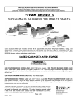
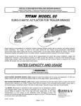
INSTALLATION INSTRUCTION AND SERVICE MANUAL Actuator/Trailer
Dealer - Please provide these instructions to the consumer. Consumer - Read and follow
these instructions. Keep them with the trailer for future reference.
_
TITAN MODEL 6 SURG-O-MATIC
ACTUATOR FOR TRAILER BRAKES
2492800 Multi-fit A
Frame
4744901 leveler
Channel
Surge actuators of this type provide a service life of approximately five years with proper installation, usage, and
maintenance. However, a well cared-for actuator can often exceed this estimate. To get the most benefit from your
_ surge actuator, follow the instructions given in-this manual and use common sense in caring for the TITAN
TITAN
MODEL 6 actuator and your entire trailer brake system.
WARNING:
Do not exceed these ratings.
RATED CAPACITY AND USAGE
7,500 POUNDS MAXIMUM GROSS LOAD with 2 5/16" coupler, 3" lunette eye or leveler channel. This is the weight
of the trailer fully loaded with all cargo and equipment. To find your trailer's Gross Load, use a commercial vehicle
scale at a truck weigh station, grain elevator, etc.
6000 POUND MAXIMUM GROSS LOAD with multi-fit ball coupler.
600 POUND MAXIMUM TONGUE LOAD with any Model 6 actuator. This is the weight applied downward by the
fully loaded trailer's coupler on the tow vehicle's hitch. Measure your trailer's Tongue Load with the tongue in a
horizontal towing position, using a commercial scale. Upward tongue loads are not permissible.
The Model 6 actuator is intended for use with recreational trailers subject to more
frequent use, light utility trailers, and light occasional-use industrial trailers, which are
towed by passenger cars and pickups. The actual in-service rating is limited to that of
the ball and hitch being used or the trailer manufacturer's G.V.W.R. shown on the
certification label, whichever is lower.
#24034 8-01
Page 1 of 6
TITAN
A Titan Wheel Company
2345 East Market Street
Des Moines, IA 50317
PH: 800-832-8781
FAX: 515-265-9201
MODEL 6 ACTUATOR INSTALLATION INSTRUCTIONS
Surge braking requires the installation of an actuator at the tongue of the trailer.
The “surge" or “push" of the trailer toward the tow vehicle automatically synchronizes the trailer brakes with the tow vehicle
brake. As the trailer pushes against the tow vehicle the actuator telescopes together and applies the force to the master cylinder,
supplying hydraulic pressure to the brakes.
The Model 6 Actuator is completely assembled and ready to bolt or weld into place.
1. Bolt or weld the actuator to the tongue. Light weight tongues require spacer tubes inside for
reinforcement when bolting. Attachment strength should equal 1-1/2 times trailer G.V.W.R.
2. Install hydraulic brake lines on the trailer as described in the installation manual supplied with the brakes. Be sure
to use a flexible hose when connecting the master cylinder to the hydraulic line on the trailer. This is necessary
because the master cylinder is spring mounted to provide overload protection.
3. Fill the system with DOT-3 heavy duty hydraulic fluid using a pressure type brake bleeder. (This type of
brake bleeder is available at your local automotive jobber.) Follow manufacturer's directions.
Install bleeder hose on first wheel cylinder to be bled; if tandem axle trailer, bleed rear axle first. Have loose end
of hose submerged in a glass container of brake fluid to observe bubbling.
By loosening the bleeder screw located in the wheel cylinder one turn, the system is open to the atmosphere
through the passage drilled in the screw. The bleeding operation is complete when bubbling stops. Be sure to
close bleeder screw securely.
Repeat bleeding operation at each wheel cylinder. During the bleeding process, replenish the brake fluid so the level does
not fall below half full level in the master cylinder reservoir.
4. After bleeding is completed, make sure master cylinder is filled to 3/8" below the top of the reservoir
and filler cap is securely in place.
HITCHING TRAILER
1. The towing hitch and ball must have a rating equal to or greater than trailer GVWR.
2. Multi-fit Ball coupler will accept 1-7/8", 50MM and 2" trailer balls. Tighten hand wheel to secure ball in socket.
Make certain ball latch is in correct position to retain the ball, and that the hand wheel lock is clicking while
tightening. You must depress the lock to loosen hand wheel in order to un-hitch trailer. Do not tow trailer if
coupler is damaged.
3. Connect safety chains using crossed pattern under tongue, or follow trailer manufacturer's directions.
4. Connect breakaway S-hook.
5. The breakaway system should only operate after both the coupling and safety chains have failed. The
breakaway is not a parking brake.
6. Should the breakaway be accidentally applied while un-hitching, pry the spring clip out of notch to
release lever.
7. Sway control devices that restrict operation of the actuator cannot be used. The actuator must be free
to telescope in response to braking requirements.
#24034
Page 2 of 6
MODEL 6 ACTUATOR INSTALLATION INSTRUCTIONS
8. Weight distributing (equalizing) hitches have been an important part of trailering for many years. They shift
excess tongue weight from the end of the tow vehicle by distributing it across all vehicle and trailer axles.
Leveling the tow vehicle and the trailer reduces the stress on the suspension components and increases towing
stability.
All TITAN surge brake actuators are fully compatible with equalizing hitches. When using weight distributing
hitches with TITAN actuators, observe the following rules:
1)
Allow six to eight inches of free chain length,
2)
The chains must be vertical (straight up and down) under pulling load, and
3)
Tongue weight beyond the specified actuator rating WILL interfere with brake
performance.
The above statement summarizes TITAN's three "rules of thumb" for equalizer/actuator compatibility. Each rule
contributes to optimum trailer braking.
RULE #1: Allow six to eight inches of free chain length. This means that the equalizer's chains must be at least
six to eight inches long between the spring bars and the hook-up brackets (which attach the chains to the
trailer). Surge brake actuators must be free to compress their internal master cylinder. Shorter lengths of
chain will limit the distance the actuator can move, and this restricts the unit's braking.
RULE #2: The chains must be vertical (straight up and down) under pulling load. During towing, these chains
must be aligned straight up and down. This should be confirmed on level ground with the trailer coupled (using
the equalizing hitch) to the tow vehicle. After checking that the actuator is in its towing position (not
compressed), adjust the position of the hook-up brackets on the trailer until the chains are vertical. If the chains
are angled forward or back on the TITAN actuator, they have a tendency to either impede the braking action by
limiting the distance the actuator can stroke or prematurely apply the brakes by pulling the trailer forward
relative to the tow vehicle_.
RULE #3: Tongue weight beyond the specified actuator rating WILL interfere with brake performance. Weight
distributing hitches spread tongue weight over the axles of both the tow vehicle and the trailer by applying
leverage against the trailer tongue and actuator/coupler. This additional force and torque on the trailer system
approximately doubles the load on the actuator, potentially exceeding its load rating.
For example, a fully-loaded trailer with a hitched tongue weight of 250 pounds might be equipped with a TITAN
Model 6 actuator. A weight distributing hitch would then cause the actuator to receive the equivalent of a 500
pound tongue load. Since 500 pounds is less than the TITAN Model 6 actuator's 600 pound tongue load rating,
this set-up would be acceptable. If a similar trailer has a 350 pound tongue weight, and once again an equalizer
is hooked up, the actuator would perceive a 700 pound tongue load. That would put the system above the 600
pound tongue load rating of the actuator. Since the excess tongue load on a surge actuator can cause it to
stroke less freely (resulting in less effective braking), this would be an inappropriate set-up.
Two factors in selecting towing equipment are gross trailer weight (GTW) and tongue load (TL). GTW is the
weight of the trailer fully loaded in its actual towing condition. This can be measured by placing the fully loaded
trailer on a vehicle scale. TL is the downward force exerted on the trailer hitch ball by the trailer coupler. In most
cases it is 10% to 15% of the GTW.
With a heavier tongue load, roller kits are available. The roller kit attaches directly to the actuator, and extends
back to a roller which rides on the trailer's tongue, allowing a higher tongue weight by shifting the equalizer's
added load to the tongue roller instead of the actuator/coupler. Consult your trailer manufacturer, or your
equalizer manufacturer for more information on roller kits.
9. The actuator is designed for use with Free-Backing trailer brakes. Do not block action in order to back
up with other type of brakes. Failure to remove block will also prevent forward braking.
#24034
Page 3 of 6
MODEL 6 ACTUATOR INSTALLATION INSTRUCTIONS
MAINTENANCE
1. Before towing check that brake fluid reservoir is at least half full. If not, re-fill to 3/8 inch below the top
of the reservoir with DOT 3 brake fluid. Check for leaks and repair as required.
2. A film of grease on the coupler will extend coupler and ball life while eliminating squeaking. Wipe
clean and renew film each time trailer is used.
3. Before towing, examine the actuator for bent parts or wear. Replace parts as necessary. Check to
determine that mounting bolts are tight and welds not cracked.
4. There are no adjustments on the actuator.
5. Actuator travel (over one inch) shown by front roller path indicates a need to adjust the brakes. Adjust per instructions found in
brake installation manual. In general, back-off adjusters 10 clicks from locked
rotation. Adjust Free-Backing brakes by rotating in forward direction only. Failure to adjust may result in loss of braking.
WARNING
Saltwater, granular fertilizers and other corrosive materials are destructive to metal. To prolong the life of a braking system
used under corrosive conditions, we recommend that the Actuator be flushed after use with a high pressure water hose. Be
sure to re-grease bearings and oil all moving parts after the unit has dried. At the end of the season, when unit is to be stored,
remove the brake drums and clean inside the brakes. Pack wheel bearings before drum is installed. Failure to properly and
adequately grease and maintain the actuator could weaken it and/or cause it to fail and result in serious injury and/or property
damage.
MODEL 6 ACTUATOR PRODUCT LIST
Part # Drum
4079200
Part # Disc
4747200
4079200317
2 5/16" coupler
Inner
4067700183
Outer
2480100183
2 5/16" coupler
4067700183
2480100183
2 5/16" coupler
4067700317
2480100317
4067600
2 5/16" coupler, A frame
4067700183
2493000
4093200
3" lunette eye
4045600183
2480100183
2480100183
4748000
3" lunette eye
4045600183
4045500
3" lunette eye, A frame
4045600183
2480000
multi fit coupler
4391600
2480100183
multi fit coupler
4391600
2480100183
multi fit coupler, A frame
4391600
2493000
leveler channel
4717600317
4745100317
leveler channel
4717600317
4745100317
leveler channel
4717600183
4745100183
4747900
2492800
4744900
4748100
4744901
4748101
2493000
leveler channel
4717600183
4745100183
4022300
multi fit coupler
4391600
2493201
4057900
less coupler, A frame
1776900
2493000
1777401
master cylinder w/mtg brackets
1777405
#24034
Description
master cylinder w/mtg brackets
Page 4 of 6
KEY NO.
1
1A
2
3
4
5
6
6
7
8
9
10
11
12
13
14
*15
16
17
18
19
20
21
22
23
24
25
26
27
28
29
*30
*31
*32
*33
*34
*35
*36
*37
38
39
PART NO.
2480100183
2493000
1020900
1776300
1776600
0799700
1776700
4350700183
4594100
1055500
1780300
1781500
1861900
1776200
1027300
4390500
2496400
1027100
1755600
1209800
0797600
0782000
1027400
1242600
0829100
1777300
0815200
1777200
4391600
1831600
1806600183
2338100
1809000
4335800
4336800
2338300
2420000
2339000
2339100
4045600
4067700183
1502600
4045400
1848700
480800
DESCRIPTION
Outer Case Assembly
Outer Case Assembly
Bearing
Front Roller
Front Roller Pin
Cotter Pin 1/8 x 3/4
Front Roller Cover #6000
Front Roller Cover #7500
Breakaway Lever with Pin
S-Hook - Part of 4594100
Breakaway Spring
Hex Bolt 5/16 x 1/2 Self Tapping
Washer
Cylinder Mounting Plate
Hex Bolt 3/8 NC x 5
Push Rod Assembly
Lock-Ring
Master Cylinder
Master Cylinder Cap with Gasket
Connector, 1/64 Orifice
Nut - Hex 3/8 NC
Washer 3/8
Spring
Damper
Rear Roller
Master Pin
Cotter Pin
Damper Pin
Inner Slide Assembly with Bolt & Locknut
Washer
Cover
Latch Bolt
Lock Plate
Ball Latch
Compression Spring
Hand Wheel Lock
Hand Wheel
Bolt - Hex 7/16 NF x 2-5/8
Locknut - Hex 7/16 NF Thin
Inner Slide w/3" Lunette Eye
Inner Slide w/2-5/16" Ball Coupler
Master Cylinder Repair Kit Wagner #13634
Multi-Fit Coupler Repair Kit (Bolt and Locknut Replace Riveted
Pin)
2-5/16" Ball Coupler Repair Kit
Back Up Valve Kit
*These parts are included in the 40454 Coupler Repair Kit.
Page 5 of 6
QUANTITY
REQUIRED
1
1
2
1
1
2
1
1
1
1
1
4
1
1
2
1
1
1
1
1
2
2
2
1
2
1
1
1
1
1
1
1
1
1
1
1
1
1
1
1
1
1
1
1
1