1
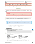
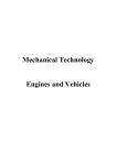
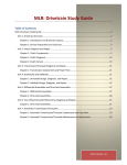
Name_________________________________________________________ Date__________________
Instructor______________________________________________________ Period_________________
Project 3: Job 12—Remove, Inspect, and Reinstall a CV Axle
After completing this job, you will be able to remove, inspect, and reinstall a CV axle.
Instructions
As you read the job instructions, answer the questions and perform the tasks. Print your answers
neatly and use complete sentences. Consult the proper service literature and ask your instructor for help as
needed.
Warning
Before performing this job, review all pertinent safety information in the text and
discuss safety procedures with your instructor.
Procedures
1. Obtain a vehicle to be used in this job. Your instructor may direct you to perform this job on a
shop vehicle.
2. Gather the tools needed to perform the following job. Refer to the tools and materials list at the
beginning of the project.
Note
The following is a general procedure for CV axle service, including typical CV
joint repair and CV joint boot replacement. Some Rzeppa and tripod joints cannot
be repaired; the entire assembly, including the boot, must be replaced. Also, some
boots are made in two pieces and can be changed without removing the axle from the
vehicle. Always consult the manufacturer’s service manual for exact CV joint repair or
boot replacement procedures.
Remove a CV Axle
1. Disconnect the battery negative cable.
2. Place the vehicle transmission in neutral.
3. Loosen the nut holding the CV axle stub shaft to the wheel hub and bearing assembly.
4. Raise the vehicle.
III.D.4
III.E.3.3
Warning
The vehicle must be raised and supported in a safe manner. Always use an approved
lift or jack and jack stands.
5. Remove the wheel from the axle to be serviced.
6. Cover the outer CV boot with a shop cloth or boot protector.
7. If needed, remove the tie rod end nut and use a ball joint separator to free the tie rod end from the
steering knuckle.
Copyright
by Goodheart-Willcox Co., Inc.
71
Project 3: Job 12—Remove, Inspect, and Reinstall a CV Axle (continued)
8. Remove the stub shaft nut. A special deep socket may be needed to remove the nut, Figure 12-1.
Note
On some vehicles, it is necessary to remove the brake rotor, caliper, and wheel speed
sensor to gain access to the CV axle shaft assembly.
9. Remove the CV axle shaft assembly from the steering knuckle. Some shafts slide from the hub,
while others must be pressed out.
Note
Removal of the CV axle shaft assembly from the steering knuckle may require the
removal of the tie rod end, strut assembly, or lower ball joint. Consult the proper
manufacturer’s service manual for exact procedures.
10. Remove the CV axle shaft assembly from the transaxle with a suitable puller or pry bar. If the
transaxle uses a stub shaft that is attached to the CV axle by flanges, remove the bolts attaching
the flanges.
Note
Cap the transaxle opening to prevent oil loss.
Figure 12-1. A special deep socket is sometimes needed to remove the stub shaft nut. These sockets are
usually sold in sets of three—30 mm, 32 mm, and 36 mm.
72
Copyright by Goodheart-Willcox Co., Inc.
Name_________________________________________________________
Project 3: Job 12 (continued)
Repair a CV Joint and Replace the Boot
1. Lightly clamp the axle shaft in a vise with soft jaws.
2. Remove the clamps from the boot of the CV joint to be serviced (or from the boot to be
replaced).
3. Pull the boot back from the CV joint and remove enough grease to further disassemble the
CV joint.
4. If applicable, remove the clip holding the CV joint to the axle shaft.
5. Place alignment marks on the joint housing and the axle shaft to aid in reassembly.
6. Pull or tap the CV joint from the axle shaft.
7. Remove the CV joint boot from the axle shaft.
III.D.1
III.D.4
III.E.3.4
Note
Proceed to step 14 to continue with boot replacement only.
8. Disassemble the CV joint by one of the following procedures, depending on the CV joint type.
List the type of joint(s) to be serviced:________________________________________________
Rzeppa Joint
a. Tap the bearing cage downward with a brass drift, Figure 12-2, until the ball on the opposite
side can be removed through the cage opening.
b. Repeat the previous step until all balls are removed.
c. Remove the cage and inner race from the housing.
Figure 12-2. Tap the bearing cage downward until the first ball can be removed. Repeat the process until all
balls are out.
Bearing cage
Copyright
by Goodheart-Willcox Co., Inc.
Inner
race
Brass drift
73
Project 3: Job 12—Remove, Inspect, and Reinstall a CV Axle (continued)
Tripod Joint
a. Remove the snap ring or clip holding the joint together, Figure 12-3.
b. Pull the tripod assembly from the housing.
c. Remove the tripod assembly from the shaft. Tripod joints may be held in place by a clip or may
be pressed on the shaft. Consult the service information for exact procedures to avoid damaging
the joint or shaft.
Note
Some CV joints are not serviceable and must be replaced as a unit.
9. Wash all parts in solvent and dry with compressed air.
10. Inspect all internal CV joint parts for excessive wear, crack or chips, and scoring.
Describe their condition:___________________________________________________________
11. Check the joint splines and threads for damage.
Describe their condition:___________________________________________________________
12. Report any CV joint component defects to your instructor. Then, determine which parts must be
replaced.
13. Obtain the proper replacement parts and compare them with the old parts to ensure that they are
the correct replacements.
14. Lightly lubricate all CV joint parts before proceeding.
Figure 12-3. Many tripod joints are held in place by a clip, as shown here, or a retaining collar.
(DaimlerChrysler)
Wire ring tripod retainer
Housing
74
Copyright by Goodheart-Willcox Co., Inc.
Name_________________________________________________________
Project 3: Job 12 (continued)
15. Align and install all CV joint parts according to the manufacturer’s instructions.
16. If the CV joint boot has a one-piece clamp, slide the clamp onto the axle shaft. Often, it is easier
to place the clamps on the boot before installing it.
17. Install the CV joint boot on the axle shaft.
Note
It may be necessary to position the small end of the boot lip face in line with a mark or
groove on the shaft.
18. Place the small clamp over the groove at the small end of the boot and tighten it by hand.
19. Place sufficient grease in the boot cavity to provide lubrication for the CV joint during vehicle
operation.
Caution
CV joints must be lubricated with special grease, usually supplied with the
replacement joint parts or boot. Do not use ordinary chassis or wheel bearing grease.
20. Position the CV joint over the splines of the axle shaft.
21. Engage the splines and tap the joint into position with a wooden or rubber hammer.
22. Install the joint-to-shaft clip, if used.
23. Pull the CV joint boot over the CV joint housing. Ensure that the boot end fits snugly into the
matching groove in the housing.
Caution
Ensure that the boot is not twisted or otherwise deformed during the installation
process.
24. Place the large clamp over the groove in the boot. Tighten the clamp by hand.
25. Fully tighten both boot clamps using the correct special tool.
Caution
Do not cut through the boot by overtightening the clamp.
26. Check for free movement of the CV joint and otherwise ensure that it is properly assembled.
Install a CV Axle
1. Install the inboard stub shaft of the CV axle assembly into the transaxle.
2. Install the outboard stub shaft of the CV axle assembly into the steering knuckle.
3. Install the stub shaft nut on the outboard shaft.
4. Adjust front wheel bearing preload, if necessary.
5. Install the brake rotor, caliper, and wheel speed sensor as needed.
Copyright
by Goodheart-Willcox Co., Inc.
III.D.4
III.E.3.3
75
Project 3: Job 12—Remove, Inspect, and Reinstall a CV Axle (continued)
6. Reinstall the wheel.
7. Lower the vehicle.
8. Install the battery negative cable.
9. Start the engine.
10. Check for proper brake operation.
11. Road test the vehicle.
Job Wrap-Up
1. Clean the work area and return any equipment to storage.
2. Did you encounter any problems during this procedure? Yes ___ No ___
If Yes, describe the problems:_______________________________________________________
What did you do to correct the problems?_ ____________________________________________
3. Have your instructor check your work and sign this job sheet.
Performance Evaluation—Instructor Use Only
Did the student complete the job in the time allotted? Yes ___ No ___
If No, which steps were not completed? ____________________
How would you rate this student’s overall performance on this job?_________________________
1–Excellent, 2–Good, 3–Satisfactory, 4–Unsatisfactory, 5–Poor
Comments:___________________________________________________________________
____________________________________________________________________________
____________________________________________________________________________
INSTRUCTOR’S SIGNATURE_ _________________________________________________
76
Copyright by Goodheart-Willcox Co., Inc.