1
Installing the Electricity and Gas to the Appliance
A
D
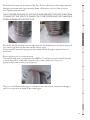
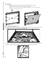
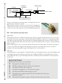
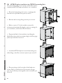
In order to install gas to the fireplace, check the operating pressure or install the network cable, the
glass and burner tray needs to be removed.
D1
Power Supply
B
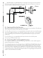
Whilst the cavity is being created consideration should be given to appropriate location of a standard
3 pin, EARTHED 230/240V power outlet. This must be within 1.0m of the rear bottom right hand
corner of the appliance.
C
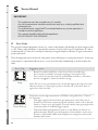
IMPORTANT: Locating the power outlet within the cavity makes the installation very neat but
the provision MUST be made to be able to switch the power supply off and on (electrical isolation
switch) and MUST be accessible after the heater has been installed. This is normally done by means
of a separate switch which must be located adjacent to the appliance as per AS/NZS 5601.1.2010.
This will allow service technicians to isolate the power supply before performing service work on the
appliance.
This appliance must not be located directly below a socket outlet.
D
This appliance will draw a maximum of 2 Amps from a 230/240V supply.
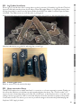
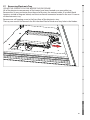
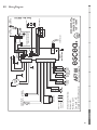
An electrical wiring diagram is located underneath the electronic tray, and also in the rear of this
manual (Service section).
D2
Removing the Glass
E
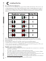
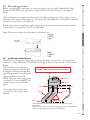
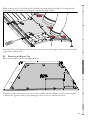
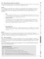
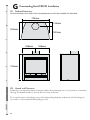
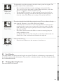
The AF700 fireplace has two layers of glass; the inner glass seals the firebox and is called the primary glass, the outer glass is called the secondary glass.
Secondary Glass
2
SERVICE
1
G
F
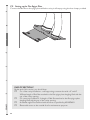
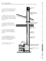
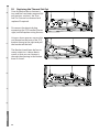
1. Turn the upper glass brackets towards the centre of the fire to release the glass.
2. Pull the top of the glass toward you slightly, lift the glass out of the bottom glass retainer and
carefully set glass aside.
25