1
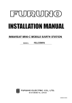
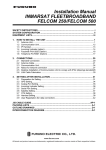
INMARSAT B MOBILE EARTH STATION
FELCOM 82A ... (For Class 1)
FELCOM 82B ... (For Class 2)
Your Local Agent/Dealer
9-52 Ashihara-cho,
Nishinomiya, Japan
Telephone :
0798-65-2111
Telefax :
0798-65-4200
All rights reserved.
Printed in Japan
FIRST EDITION : DEC. 2000
D
PUB.No. IME-56240-D
( TENI
) FELCOM 82A/B
: MAY. 07,2002
*00080907701*
*00080907701*
*00080907701*
*IME56240D00*
*IME56240D00*
*IME56240D00*
SAFETY INSTRUCTIONS
WARNING
WARNING
Do not open the equipment
unless totally familiar with
electrical circuits and
service manual.
Ground the equipment to
prevent electrical shock
and mutual interference.
ELECTRICAL Only qualified personnel
should work inside the
SHOCK
equipment.
HAZARD
Confirm that the power supply voltage
is compatible with the voltage rating
of the equipment.
Do not approach the radome closer than 6 meters
when it is transmitting.
Connection to the wrong power supply
can cause fire or equipment damage. The
voltage rating appears on the label at the
rear of the display unit.
The radome emits radio
waves which can be harmful
to the human body, particularly the eyes.
Use the correct fuse.
Use of a wrong fuse can cause fire or
equipment damage.
RF power density
on antenna aperture distance
100W/m2
1.0 m
10W/m 2
6.0 m
Keep the following compass safe
distances.
Standard Steering
Turn off the power at the
mains switchboard before
beginning the installation.
Post a sign near the switch
to indicate it should not be
turned on while the equipment is being installed.
Fire, electrical shock or
serious injury can result if the
power is left on or is applied
while the eqiuipment is being
installed.
i
Antenna Unit
1.60 m
1.10 m
Communication Unit
2.10 m
1.40 m
Terminal Unit
1.10 m
0.80 m
Junction Box
1.10 m
0.90 m
Handset
2.05 m
1.40 m
Telex Distress Alert Button
Telephone Distress Button
Incoming Indicator
0.80 m
0.60 m
Printer
1.00 m
0.80 m
Facsimile
1.60 m
1.20 m
Telephone
0.50 m
0.40 m
TABLE OF CONTENTS
EQUIPMENT LISTS..................................iii 3 INITIAL SETTINGS ................................34
3.1 Hatch Direction and Heading Adjustment 34
3.2 Setting of Telephone (option) ..................35
SYSTEM CONFIGURATION ....................v
3.3 Facsimile PFX-50 Setting........................36
1 MOUNTING OF UNITS..........................1
1.1 Antenna Unit...........................................1
1.2 Communication Unit ...............................9
4 SYSTEM SETUP....................................38
1.3 Terminal Unit (for class 1 only)................11
1.4 Printer ....................................................12
1.5 Junction Box IB-313................................13
1.6 Telex Distress Alert Button IB-352...........14
4.1 Setting Up ..............................................38
4.2 Registering Answerback Code
(Class 1 only)............................................39
4.3 OID/DID Setting......................................40
4.4 Setting of Gyro Converter .......................42
1.7 Telephone Distress Button IB-362...........14
5 9.6K DATA COMMUNICATIONS ...........50
1.8 Handset Hanger RB-2721B or
5.1 Installation ..............................................50
RB-2721B/362 ..........................................15
5.2 Checking Operation ................................50
1.9 Mounting of Optional Equipment .............16
5.3 Modem Setup .........................................51
2 WIRING..................................................20
5.4 Dial-up Setup..........................................54
2.1 Standard Wiring......................................20
2.2 Handset IB-882/IB-882-362 ....................24 6 CHANGING POWER SPECIFICATIONS
.............................................................58
2.3 Junction Box IB-313................................25
2.4 Wiring at the Antenna Unit ......................26
2.5 Telephone FC755D1 (option) ..................26 PACKING LISTS.......................................A-1
2.6 Facsimile PFX-50 (option) ......................27
OUTLINE DRAWINGS ..............................D-1
2.7 Incoming Indicator IC-372 (option) ..........28
2.8 Gyrocompass .........................................29
SCHEMATIC DIAGRAMS.........................S-1
2.9 Telex Distress Alert Button IB-352/
Telephone Distress Button IB-362............30
2.10 DGPS Decoder.....................................31
2.11 Checking the Installation .......................32
ii
EQUIPMENT LISTS
Standard Supply
Name
Type
Code No.
Qty
Remarks
Antenna Unit
IB-182
-
1 set
Communication Unit
IB-282
-
1 set
Terminal Unit
IB-582
-
1 set
Junction Box
IB-313
-
1 set
Handset
IB-882
-
1 set
IB-882-362
-
IB-352
-
1 set
Class 1 only
IB-362
-
1 set
Only when handset IB-882 is selected
Printer
PP-510-82
-
1 set
Installation Materials
CP16-01300
Telex Distress Alert
Class 1 only
with handset hanger RB-2721B
with handset hanger RB-2721B-362
Button
Telephone Distress
Button
CP16-01310
000-043-215
1 set
Supplied with antenna
No antenna cable,
unit
w/CP16-01101
000-043-216
w/30m antenna
cable, CP16-01101
CP16-01320
000-043-217
w/50m antenna
cable, w/CP1601101
CP16-01330
000-043-218
w/100m antenna
cable, w/CP1601101
CP16-01811
004-444-210
1 set
Supplied with
For CP16-
Communication Unit
01310/01320
CP16-01812
004-444-220
For CP16-01330
CP16-01813
004-444-230
For CP16-01300
CP16-01820
000-043-387
CP16-01830
004-444-260
1 set
1 set
Supplied with Terminal
Cable assy, Power
Unit
cable, CP16-01821
Supplied with Handset
Connector assy
(5m), CP05-08002
CP16-01840
004-444-270
Connector assy
(10m), CP05-08002
CP16-01850
004-444-280
Connector assy
(20m), CP05-08002
Accessories
CP16-01701
004-444-290
1 set
Supplied with Printer
CP16-01102
004-441-450
1 set
Supplied with Junction Box
CP16-01801
004-444-300
1 set
Supplied with Telex Distress Alert Button
CP16-01801
004-444-300
1 set
Supplied with Telephone Distress Button
FP16-00400
000-043-388
1 set
Supplied with Terminal Unit
Mini keyboard,
FP16-00401
FP16-00100
000-043-258
1 set
Supplied with Printer
Recording
paper
iii
Optional Supply
Name
Type
Incoming Indicator
IB-372
Code No.
-
1 set
Qty
w/CP16-01801
Remarks
Printer
PP-510-82
-
1 set
w/CP16-01701, FP16-00100
Facsimile
PFX-50
-
1 set
w/CP16-00590
Telephone
FC755D1
-
1 set
w/CP16-00511, 00512
Antenna Cover
QB05-1801
100-079-480
1
Modular Jack Box
OP16-10
000-043-278
1
Box type
Modular Jack Box
OP16-11
000-043-279
1
Flush mount type
Modular Jack Set
OP16-13
000-043-228
1
Lifting Metal
OP16-15
004-442-460
1
5-pair cable
CO-SPEVV-SB-C
000-560-452
1
0.2x5P
000-103-868
For junction box, 20m
000-103-869
For junction box, 30m
000-132-829
For junction box, 40m
000-132-828
For junction box, 50m
1-pair cable
1
For junction box, 10m
CO-SPEVV-SB-C
000-110-681
0.2x1P
For junction box, 10m
000-138-789
For junction box, 20m
000-138-790
For junction box, 30m
000-138-791
For junction box, 40m
000-138-792
For junction box, 50m
Ribbon Cartridge
SP-16051NB
000-133-029
1
Printer Paper
A2 1PLYW
000-134-903
1 set
12 rolls
A2 2PLYWW
000-134-780
1 set
12 rolls
K52
000-806-564
1 set
12 rolls, B4 size
000-806-565
1 set
12 rolls, A4 size
Recording paper
257X50M25TRU
K52
216X50M25TRU
Transformer
FIT-100
000-139-903
1
220 VAC→100 VAC
HSD I/F
KLASHOPPER
000-142-952
1
For laptop computer, PMCIA
PCMCIA400
KLASHOPPER
card type II, w/cable
000-142-951
PCI-400
For desktop computer, built-in
type
iv
MJ-2S
v
MJ-2S
INCOMING INDICATOR IB-372
Max. 3 units
100 VAC
FACSIMILE PFX-50
TELEPHONE FC755D1
100 VAC FACSIMILE PFX-50
MJ-2S
FACSIMILE PFX-50
TELEPHONE FC755D1
100V AC
TELEPHONE FC755D1
Standard supply
Option
Local supply
HSD
PC
HSD IF
DGPS
DECODER
GYROCOMPASS
PC
PC-AT compatible
9.6K DATA
HANDSET
IB-882/IB-882-362
JUNCTION
BOX
IB-313
COMMUNICATION
UNIT
IB-282
ANTENNA
UNIT
IB-182
*: For use with Handset IB-882.
TELEPHONE DISTRESS BUTTON IB-362*
TELEX DISTRESS ALERT BUTTON IB-352
(FELCOM 82A only)
NAVIGATOR
(FELCOM 82A only)
TERMINAL
UNIT
IB-582
PRINTER
PP-510
Ship's mains
100-115/
220-230 VAC
1∅, 50/60 Hz
SYSTEM CONFIGURATION
This page is intentionally left blank.
1 MOUNTING OF UNITS
This chapter describes how to mount the units of the system, including optional equipment.
1.1 Antenna Unit
1.1.1 Mounting considerations
General
Interfering objects (especially metallic objects such as masts) near the antenna can, in the
worst case, prevent reception or transmission. Further, RF radiation from the antenna will
affect the human body. Keep these and the following guidelines in mind when selecting a
mounting location for the antenna unit.
Secure unobstructed path in all directions
The ideal mounting location secures an unobstructed path between the antenna unit and the
satellites, from horizontal to zenith. In order words, whatever the direction the antenna unit is
pointing there are no interfering objects within the main beam (12 degrees). While this might
be feasible on some vessels, on others it is impossible due to space considerations. The
antenna unit should be located at least 3 meters away from masts having a diameter less
than 15 centimeters.
Beam
Direction
12
4300 mm
Beam direction
Select a location low in vibration
The maximum permissible vibration amplitude in three axis direction should be as shown in
the table at the top of the next page. Consult with the shipyard to determine the mounting
location which meets the requirements shown in the table.
The table at the top of the next page is taken from Inmarsat’s System Definition Manual
(SDM) and defines frequency and maximum vibration amplitude.
1
Freq. Range
4 to 10 Hz
Max. Amplitude
2.54 mm (max. 9.8 m/s²)
10 to 15 Hz
0.76 mm (max. 6.86 m/s²)
15 to 25 Hz
0.40 mm (max. 9.8 m/s²)
25 to 33 Hz
0.23 mm (max. 9.8 m/s²)
Half Vibration
Max. amplitudes
Locate away from passengers and crew
Radio waves can be harmful to the human body. Since safe distances vary by country and
ship construction there is no uniform formula for calculating safe distance. However, below
are general guidelines.
• Unprotected persons should not approach an area in which the radiation level is higher than 100
W/m2. For an Inmarsat B antenna, the radiation level is less than 100 W/m2 at 1 meter distance from
the radome surface.
• Unprotected persons should not approach within 6 meters of a transmitting Inmarsat antenna.
WARNING
Do not approatch within 6 meters of the
antenna radome when it is transmiting.
Microwave radiation can be harmful to
the human body, particularly the eyes.
Minimum distance from other antennas
HF antennas, communication/navigation antennas:
The FELCOM 82 antenna should be at least 5 meters from a HF antenna. VHF, satellite
navigation antenna and other communication antennas should be at least 4 meters away.
Radar:
The antenna for the FELCOM 82 should be at least 5 meters away to protect the low noise
amplifier in the radar antenna. However, if this distance cannot be secured be sure the
FELCOM 82 antenna unit is not within the radar beam.
2
More than 5 m
30
20
If installed within 5 m of
radar antenna, the antenna
unit must not be within the
radar beam.
Distance from antenna radar
Compass safe distance
Locating the antenna unit too close to a compass can affect compass performance. The
compass safe distance is 1.10 meters, steering compass, 1.60 meters, standard compass.
Other mounting guidelines
Other important mounting guidelines are
• Locate the antenna unit away from exhaust stacks (foreign material on the radome can interfere
with reception and transmission).
• Keep the unit away from heat sources.
• Locate the unit away from places where fuels and chemical solvents are stored.
• Keep in mind the length of the cable from the communication unit is maximum 100 meters.
1.1.2 General mounting (construction of mast)
General
To facilitate servicing, construct a mast more than 1 meter in height from the deck. The
paragraphs which follow provide guidelines for selection and construction of the mast.
Refer to the drawing at back of this manual.
Guardrail, platform
When the mast is tall, fit it with a guardrail and platform (or steps), for serviceman’s safety
and convenience.
For servicing ease, the distance between hatch and the deck (or platform) to the antenna
unit should be about 1 meter. (In most installations the serviceman stands on the platform
while checking the radome. Thus this distance should be secured for ease of servicing.)
The guardrail should be as high as possible for sufficient safety.
3
Mast strength
The mast material must be sufficiently strong to meet the demands of the marine
environment. It should satisfy the following requirements.
• It must be able to support radome mass plus at least 2.5 centimeters of ice and snow. Special
consideration should be given if the unit is operated in areas of heavy snow or freezing
temperature.
• Mast bending moment must be able to withstand expected maximum pitching, rolling and wind
pressure.
To prevent resonance at low frequencies (about 5 Hz), four stays can be fixed between the
mast and the mounting base.
Wind
Pressure
Mass
Mast
Bending
Moment
Fixing radome
Item
Mass
87 kg ± 10%
Antenna unit mass
Platform, guardrail mass
Expected ice and snow
Maximum wind pressure (at wind speed 75 m/s)
2083 N
Maximum bending moment (at wind speed 75 m/s)
1354 N•m
Maximum bending moment
1450 N•m
(at wind speed 75 m/s, muximum rolling angle)
Maximum bending moment
1730 N•m
(at wind speed 75 m/s, maximum rolling angle including 0.5 G speed added by rolling.)
4
Mounting base
A mounting base is installed between the mast and the antenna unit. Below are guidelines
for installation of the mounting base.
1. The face of the mounting base should be flat as possible (tolerance: within 2 millimeters
of the horizontal plane).
2. The mounting base should be parallel with ship’s horizontal plane (tolerance: ±1 degree).
3. The fixing bolts of the mounting base should be parallel with the ship’s keel line
(tolerance: ±2 degrees).
4. Weld a ground bolt (stainless steel, M12x40, local supply) to the mast within 50 cm of the
ground terminal on the antenna unit. The length of the ground wire (supplied) is 50
centimeters.
5. Make four holes on the mounting base to face drain holes of the antenna unit.
Make drain holes.
Mounting base
Drain holes
Changing hatch direction
The standard hatch direction is stern, as shown in 1 in the figure below. If the hatch cannot
face the stern, it may face port, starboard or bow direction as shown in 2, 3 and 4 in the
figure below. Note that the location of the cable gland changes with hatch direction. After
changing hatch direction, change the disk position setting for the limit switch. See Chapter 3.
1 Stern (standard)
2 Starboard
3 Bow
4 Port
Cable Gland
Hatch
Hatch
Hatch
Hatch
Hatch directions (view: top view)
5
Unpacking
• Check that if the antenna unit is damaged by shipment.
• Unpack the antenna unit carefully so as not to damage it.
Remove hex nut, spring washer, flat washer, large washer and fixing material to dismount
the antenna unit. This hardware can be discarded.
Eye bolt
Antenna
Fixing plate
Fixing material
Large washer
Flat washer
Spring washer
Hex. nut
Palette
Unpacking antenna unit
6
1.1.3 Mounting
Unpacking, visual inspection
Carefully unpack the radome and
check for damage.
Procedure
Lifting Rope
(Can be
supplied
together with
snackles.)
4 Radome
1. Run lifting rope through eye bolts
and shackles.
2. Cover the portion of the radome
which contacts the lifting rope with
protective material (rubber mat,
etc.), to prevent damage to the
radome when hoisting it to the
mounting location.
3. Hoist the antenna unit to the
mounting location.
4. Fix the antenna unit to the
mounting base (see note below)
with nuts, keeping in mind hatch
direction (standard direction is
stern).
Flat Washer
2 Protective
Material
Mounting Base
Spring Washer
10 mm Nut
Coat here with
silicone sealant.
13 mm Nut
FIXING OF RADOME
Shackle
1 Eye Bolt
Eye Bolt
5. If necessary, replace eye bolts
with hex. bolts (supplied).
Antenna Bottom
Mounting Base
Note1: Coat all bolts and nuts with
silicone sealant to prevent electrolytic
corrosion.
Note2: Do not use a rubber gasket on the mounting base. The face of the mounting base
should be flat as possible (tolerance: within 2 mm of the horizontal plane).
If tolerance is more than 2 mm, insert a metal spacer between the antenna bottom
and the mounting base. For earth wiring, see Chapter 2.
7
Attach electromagnetic wave caution label
Labels which warn of electromagnetic waves are supplied with the installation materials.
Attach them as follows.
1. To the radome mast where it can easily be seen.
2. In a conspicuous location in the stairwell leading to the deck where the antenna unit is
installed.
Removing ropes
The stabilizer in the radome is tied by two ropes to prevent damage to it during shipment and
installation. Cut and remove them after finishing the installation.
Rope
Rope
HPA
Antenna unit
Note 1: Turn on the switch on the HPA case after mounting the antenna unit.
Note 2: The antenna cable for FELCOM 81 may be used in case of retrofit.
8
1.2 Communication Unit
1.2.1 Mounting considerations
Vibration conditions
The mounting location should satisfy the condition of vibration amplitude tabulated below.
Freq. Range
4 to 15 Hz
Max. Amplitude
0.76 (max. 6.86 m/s²)
15 to 25 Hz
0.40 (max. 9.8 m/s²)
25 to 33 Hz
0.23 (max. 9.8 m/s²)
33 to 40 Hz
0.13 (max. 8.23 m/s²)
40 to 50 Hz
0.07 (max. 6.86 m/s²)
Half Vibration
Max. amplitudes
Environmental conditions
The mounting location should satisfy the following conditions. This unit can be mounted on
the top or underside of a table.
• The usable temperature range is –15 to +55 °C.
• Select a location which is well ventilated.
• The location should be clean, and moderate and stable in temperature and humidity.
• Be sure to leave sufficient space around the unit for maintenance and checking.
• Locate the unit well away from high power HF band radiotelephones and antenna feeders.
• Be sure the mounting location is strong enough to support the weight of the unit under conditions of
vibration normally encountered on the vessel.
9
1.2.2 Mounting
Procedure
Before mounting the unit, lay cables, fabricate connectors and establish the ground system.
Then, mount the unit as follows.
Note:Do not install the communication unit on a bulkhead because of its weight.
1. Fix the arms at both sides of the equipment to the mounting location with four tapping
screws (5x20, supplied as installation materials). The tapping screws should be fastened
loosely.
2. Slide the equipment away, and then fasten tapping screws tightly.
50/60 Hz
100-115 VAC
220-230 VAC BREAKER
GYRO
JUNCTION BOX
VDU
HANDSET
GYRO
Table top mounting
PRINTER
PRINTER VDU
24 VDC 24 VDC
MSD(9.6k)
DGPS
50/60 Hz
100-115 VAC
220-230 VAC BREAKER
Mounting on underside of table
426±0.5
4- 6 Fixing Hole
50
#: Service Space
200±0.5
#150
(required for air vent)
#100
HSD(56k/64k)
HANDSET
PRINTER VDU
24 VDC 24 VDC
VDU
DGPS
ANT
PRINTER
JUNCTION BOX
ANT
MSD(9.6k)
HSD(56k/64k)
#100
Air vent
Mounting dimensions for the communication unit
10
#150
1.3 Terminal Unit (for class 1 only)
1.3.1 Mounting location
• Leave sufficient space around the unit to permit checking and maintenance.
• Locate the unit where temperature and humidity are stable and moderate.
• Locate the unit at least 5 meters from high power communications equipment and its feeder and
antenna to prevent mutual interference.
Mounting main unit
1. Fix the hanger to the table with five tapping screws.
2. Attach connectors to bottom panel.
3. Fix the unit to the hanger by two knobs.
Mounting keyboard
To permanently fix the keyboard, do the following:
1. Attach the four “hook loop fastener 3” (small ones) to the bottom of the keyboard.
2. Attach the four “hook loop fastener 4” (large ones) to the “hook loop fastener 3” attached
to the keyboard bottom.
3. Remove seals from the hook loop fastener 4.
4. Set the keyboard on the mounting location and press down firmly.
5. Attach labels as shown on the next page.
5- 7.5 Fixing hole
125±0.5
80±0.5
125±0.5
40±0.5
#: Service space
#80
170
300
#80
POWER
ON
BRILL
BRILL
OFF
OFF
B
Label for INMAR "B"
30
35
Mounting dimensions for the terminal unit
11
#100
Label for key operation for
INMARSAT-B (16-011-5803, supplied)
Label for compass safe distance
(16-011-5804-0, supplied)
Keyboard, attaching labels
1.4 Printer
Fix the printer to the mounting location with the two mounting fixtures (supplied). See the
outline drawing at back of this manual for details.
Printer fixture 2
Printer
fixture1
200
405
Attach label for INMAR "B".
Attach label for
compass safe distance.
Printer PP-510
12
1.5 Junction Box IB-313
The usual mounting location is behind the communication unit on the bulkhead. The junction
box connects to the communication unit with a 2 meter cable, which is attached to the IB-313
at the factory. Keep this length in mind when selection a mounting location.
Be sure to leave sufficient space around the unit as shown below.
To fix the unit, open the cover and fix the unit to the mounting location with four tapping
screws.
#50
Fixing hole
4- 6
Fixing hole
#50
140
100±0.5
260
210±0.5
Fixing hole
#10
#10
Cable
entrance
#: Service space
Mounting dimensions for the junction box
13
1.6 Telex Distress Alert Button IB-352
The IB-352 is usually installed near the terminal unit. For location away from the
communications room, install it where it can be easily seen. Fix it to the mounting location
with tapping screws.
The location of the cable gland depends on the type of unit.
Pass the cable through the bushing (supplied as installation materials) at the bottom or the
rear of the unit and connect it to the terminal board referring to the interconnection diagram.
Cover the unused hole with the hole plug (supplied). Attach the sticker (supplied) to the front.
5 Fixing Hole
Terminal
Board
Cable Entry
Bulkhead type
IB-352, cover opened
1.7 Telephone Distress Button IB-362
Mounting location should be near the handset because this button changes the priority of
handset (telephone) to DISTRESS. When using the handset IB-882-362, the telephone
distress button IB-362 is not installed.
14
1.8 Handset Hanger RB-2721B or RB-2721B/362
The length of the handset cable is 5 m/10 m/20 m, so locate the handset hanger within 5
m/10 m/20 m from the communication unit. The RB-2721B/362 has a distress telephone
button.
Make a cable hole in the bulkhead referring to the figure below. Remove six screws to
detach the hanger cover, and fasten the hanger with two tapping screws (supplied) on the
desktop or bulkhead.
Note1: The magnet inside the hanger may pull the screwdriver when mounting the hanger.
Note2: Be careful not to pinch the cables at the locations marked with stars in the
illustration below when closing the hanger cover.
(77)
65
Screws
(six)
42
22
145 ± 0.5
208
12 Cable entrance hole
57
2-
4.5 Fixing hole
Fixing the hanger
Hanger cover
#
#
#
#
#
Cable entrance
#
PH10P
J1
Fixing holes
RB-2721B or RB-2721B/362
Handset, cover removed
15
1.9 Mounting of Optional Equipment
1.9.1 Mounting the Facsimile PFX-50
Refer to the drawing below. Use only the installation materials supplied.
Note: When ship’s main is 220/230 VAC, the optional transformer FIT-100 is required.
1. Attach the “rough” velcro fasteners to the mounting location as shown in the drawing
below.
2. Attach the “smooth” velcro fasteners to the underside of the PFX-50 as shown in the
drawing below.
3. Set the PFX-50 on the mounting location and press down firmly. (Equipment should not
move by ship’s vibration.)
4. Attach PFX key label (for English) to facsimile key panel.
5. Attach INMAR “B” and compass safe distance labels to a side of facsimile.
Attach label for INMAR "B".
Attach label for compass
safe distance here.
Facsimile PFX-50, side view
16
Velcro fastener (1)
(x2) for PFX-50
Velcro fastener (2)
(x2) for mounting location
Attach the velcro
fastener to the
underside.
Velcro fastener (3)
(x1) for PFX-50
Velcro fastener (4)
(x1) for mounting location
Mounting dimensions for facsimile PFX-50
1.9.2 Incoming Indicator IB-372
The IB-372 alerts shipboard personnel (by aural alarm) to incoming telephone calls and telex
and facsimile messages. For location away from the communications room, install it where it
can be easily seen. Fix it to the mounting location with tapping screws or wood screws.
The IB-372 can be installed maximum three units. For details, refer to the description for the
telex distress alert button IB-352 (page 14).
17
1.9.3 Telephone
General
The telephone can be installed on a tabletop or a bulkhead. Select a location where the unit
can easily be operated.
• For installation on a wooden table, use the mounting base and tapping screws (supplied).
• For installation on a steel table, fix the telephone with nuts and bolts.
• For bulkhead mounting, use the bulkhead mounting base (supplied with telephone accessories).
Mounting location
Select a location where temperature and humidity are moderate and stable. Secure sufficient
space around the unit for ease of operation and maintenance.
Mounting base
(Table top: Use installation materials,
Mounting
Bulkhead: Use telephone accessories.)
The mounting dimensions are given in
the outline drawing at the back of this
manual. Determine the mounting
location, leaving sufficient space
Secure mounting
around the unit, and then fix the
base with tapping
Catches
screws.
mounting base to the mounting
location. The mounting base is
different for bulkhead and tabletop
Attach handset
mounting, however the mounting
fixture here.
procedure is the same for all.
Unfasten this screw.
1. Fix the mounting base to the
mounting location with four tapping
screws (4x16).
2. On the underside of the telephone,
unfasten the screw shown in the
figure.
(The screw may be
Bottom view
discarded.) Attach vulcanizing tape
Mounting base stopper
(supplied) to the handset fixture.
Fasten the handset fixture to the
underside of the telephone with a
screw (3x14, supplied).
Handset fixture
3. The catch in the receiver cradle
functions to hang up the handset
Catch
completely. Set the catch in the
upward position as shown in left.
(To detach the handset from the
hanger, slide the handset upward.)
4. Set the telephone to the four catches in the mounting base and then slide it toward you
until you hear a click.
18
5. Attach the “SLIDE” label (supplied) to the handset.
6. Attach English language label (supplied) to the telephone.
7. Attach the label for compass safe distance (16-007-6927-0) and INMAR “B” as shown
below.
Attach label for INMAR "B".
Label (16-007-6927-0)
Telephone, attaching the label
1.9.4 HSD I/F (KLAS bland)
The optional KLASHOPPER HSD I/F, which is connected to PC, provides communication
between FELCOM 82 and a terrestrial ISDN line, at the speed of 56/64 Kbps. There are two
types of HSD I/F, PCMCIA400 (for laptop computer) and PCI-400 (for desktop computer).
For details, see the operator’s manual for KLASHOPPER.
PCMCIA400
Insert the PCMCIA Type II card to the slot of the laptop type personal computer.
Connect to the HSD(56k/64k)
port on communication unit.
MSD(9.6k)
HSD(56k/64k)
ANT
PRINTER
HANDSET
VDU
Laptop
personal
compter
GYRO
JUNCTION BOX
PRINTER VDU
24 VDC 24 VDC
DGPS
KLASHOPPER
PCMCIA400
50/60 Hz
100-115 VAC
220-230 VAC BREAKER
2m
(Attached)
D-sub 25P
(male)
Insert the PCMCIA
card to the slot.
Card
D-sub 25P0.9 m connector
(female) (Attached)
D-sub 37P
(male)
PCI-400
Remove the desktop personal computer cover, and then attach the PCI extension card to the
unused port.
Connect to the HSD(56k/64k)
port on communication unit.
MSD(9.6k)
HSD(56k/64k)
ANT
PRINTER
VDU
HANDSET
GYRO
JUNCTION BOX
DGPS
PRINTER VDU
24 VDC 24 VDC
50/60 Hz
100-115 VAC
220-230 VAC BREAKER
KLASHOPPER
PCI-400
2m
(Attached)
D-sub 37P(male)
19
Attach the PCI extension card.
2 WIRING
2.1 Standard Wiring
Antenna Unit
IB-182
0.5m
Earth wire 16S0116
*2
Terminal Unit
IB-582
(FELCOM 82A only)
*4
16S0068, 5m
*2
COM1
COM2
PRINTER
24 VDC
KEYBOARD
+
8D-FB-CV*30m*
8D-FB-CV*50m*
12D-SFA-CV*100m*
-
*2 VCTF0.75x2C, 3m
*2
*2
FELCOM 82A
only
Keyboard
BTC-5100C PS/2
Printer PP-510
*3
Handset
IB-882/IB-882-362
2m
Earth wire
08S0087
BREAKER
*2
17JE23150-02 (D8C)
5/10/20m
FELCOM 82B
only
*2
*2
MSD(9.6k)
HSD(56k/64k)
*1
ANT
VDU
PRINTER
JUNCTION BOX
HANDSET
1.2m
Pinch cores.
*2
*1
Modular jack box
Modular jack box
*1
FAX
*2
10/20/30/40/50m
CO-0.2×5P
CO-0.2×5P
Earth wire
2m
08S0087
CO-0.2×5P
Junction Box
IB-313
Communication Unit
IB-282
100/115 VAC,
16S0277, 3m 220/230 VAC,
1 . 50/60 Hz
Telephone
16S0084, 5m
*2
GYRO
50/60 Hz
100-115 VAC
220-230 VAC BREAKER
PRINTER VDU
24 VDC 24 VDC
Copper strap
*1 : Requires attachment of connector.
*2 : Connector factory-fitted.
*3 : The antenna cable for FELCOM 81
may be used.
*4 : For 30m or 50m cable, connector
factory-fitted.
Run the cable 600 + 20mm from the
cable entry on the antenna base.
*5 : When selecting IB-882-362,
IB-362 is not necessary.
*1
*1
DGPS
16S0312, 2m
Gyrocompass
*2
*2
16S0184, 3m
*1
(Crimp-on lug)
Telephone Distress
*5
Button
IB-362
10/20/30/40/50m *1 (Crimp-on lug)
Incoming Indicator
IB-372
*1 (Crimp-on lug)
Wiring diagram
20
Telex Distress
Alert Button
IB-352
2.1.1 How to attach the antenna cable connector N-P-8DFB and
N-P-12DSFA
Fabricate the antenna cable as shown below to connect the antenna unit to the
communication unit.
N-P-8DFB connector
Note: The length of the antenna cable 8D-FB-CV must not be less than 20 m.
(Dimensions in millimeters.)
Outer Sheath
Armor
Inner Sheath Shield
30
50
Cover with heat-shrink tubing and heat.
Cut off insulator and core by 10 mm.
10
Twist shield end.
Slip on clamp nut,
gasket and clamp as shown left.
Clamp Nut
Gasket Clamp
(reddish
brown)
Aluminum Foil
Fold back shield over clamp and trim.
Trim shield here.
Cut aluminum foil at four places,
90 from one onother.
Insulator
Fold back aluminum foil onto shield
and trim.
Trim aluminum
tape foil here.
1
Expose the insulator by 1 mm.
5
Expose the core by 5 mm.
Pin
Clamp Nut
Shell
Slip the pin onto the conductor.
Solder them together through the
hole on the pin.
Insert the pin into the shell.
Screw the clamp nut into the shell.
(Tighten by turning the clamp nut.
Do not tighten by turning the shell.)
Solder through
the hole.
How to attach the antenna cable connector N-P-8DFB
21
N-P-12DSFA connector
Note: The length of the antenna cable 12D-5FA-CV must not be less than 40 m.
(Dimensions in millimeters.)
Outer Sheath
Armor
Inner Sheath Shield
Remove outer sheath and armor by the
dimensions shown left.
Expose inner sheath and shield by the
dimensions shown left.
12
80
Twist shield end.
Slip on clamp nut, gasket and clamp
as shown left.
1.8
Expose the insulator by 1.8 mm.
4.5
Expose the core by 4.5 mm.
Pin
Clamp Nut
Shell
Slip the pin onto the conductor.
Solder them together through the hole
on the pin.
Solder through the hole.
Insert the pin into the shell.
Screw the clamp nut into the shell.
(Tighten by turning the clamp nut.
Do not tighten by turning the shell.)
How to attach the antenna cable connector N-P-12DSF
22
2.1.2 Power cable for printer and terminal unit
Fabricate the RM12BPG-2PH connectors and power cables for terminal unit and printer to
connect to the communication unit.
12
3
Remove outer sheath by 15 mm,
core cable by 3 mm.
Cable from Printer
Red: 1(+24V)
Black: 2(GND)
White: Cut off.
Cable from Terminal unit
White: 1 (+24V)
Black: 2 (GND)
Fabrication of power cables
2.1.3 Internal wiring change for handset IB-882-362
For the handset IB-882-362, change the wiring in the communication unit as below.
1.
2.
3.
4.
5.
Remove the upper cover from the communication unit.
Disconnect the connector J18 from the CPU Board (16P0182).
Unfasten the cable clip shown below and pass the cable removed at step 2 through it.
Refasten the cable clip.
Attach the PH5P connector coming from the HANDSET port to J18 on the CPU Board
(16P0182).
HANDSET
JUNCTION BOX
J17 J18
Cable clip
CPU Board
16P0182
Communication unit, upper view
6. Close the cover of the communication unit.
23
2.2 Handset IB-882/IB-882-362
Take appropriate measures to ensure water does not penetrate through hole in bulkhead
made for the handset cable.
2.2.1 8-pair cable between the hanger and communication unit
8-pair cable (supplied, 5 m/10 m/20 m) should be fabricated as below.
Unused cables should be cut.
BRN GRN RED GRYORG BLU YEL BLK
80
Connect to the appropriate
terminal block in the hanger.
Anticorrosive
Sheath
Drain wire
Push the appropriate switch down
to insert/pull out the cable.
6
Connect to the terminal block #16
in the hanger.
1
9
2
10
3
4
11 12
5
13
6
7
14 15
8
16
Drain wire should be covered by
vinyl sheath, or soldered to the
shield in the cable to be grounded.
Cable Fabrication
WHT
Drain
ORG, GRN, BRN,
PPL PNK BLU,
WHT
WHT WHT
RED
RB-2721B/362 only
Terminal Block Arrangement
Cable arrangement and terminal block arrangement on handset
Pass the above cable through the entrance hole at the back of the hanger, and attach to the
appropriate block. Cover the hole with soft putty, from the inside of the hanger.
2.2.2 Handset cable
Connect the handset cable to the connector at the bottom of the hanger.
24
2.3 Junction Box IB-313
You will need a small slotted-head screwdriver to open terminals. Insert the screwdriver in
terminal to open it. Then insert wire core. For cables with shields be sure the shields are well
grounded in the cable clamps.
1
2
3
Cover
Core 7 mm
Terminal
Board
Cable clamp for
grounding cable shield
To Communication Unit
Nylon clamp for
fixing cable
Procedure
Use this screw for
grounding.
1. Insert driver from direction 1 .
2. Tilt slightly toward 2 .
3. Insert cable core to 3 .
Earth wire
Telephone/Facsimile
Navigator
Telex Distress
Alert Button
Telephone Distress Button
Incoming Indicator
Junction box terminal
25
2.4 Wiring at the Antenna Unit
2.4.1 Fixing of antenna cable
Lead in the antenna cable 600 ± 20 mm (marked with vinyl tape) from the cable entry in the
antenna base. Connect the coaxial connector and fix it by the cable clamp.
2.4.2 Ground
A ground wire (IV-14SQ, 500 mm) comes with the antenna unit. Connect it to fixing bolt at
the base of the radome and the ground bolt on the mast.
Ground wire
(500 mm)
Connect the
coaxial connector.
Fix the
antenna cable.
Antenna Base
Mast
Cable entry
Weld bolt.
Coat here with
silicone sealant.
Antenna cable, fixing and grounding
2.5 Telephone FC755D1 (option)
Connect the cable from the telephone to TEL1, 2, or 3 in the junction box. Use the modular
jack box (supplied as installation material). Connect the CO-SPEVV-SB-C 0.2x1P cable
(option, 1-pair cable, 10/20/30/40/50m) or TTYCS-1 (Japan Industrial Standard (JIS) cable,
or equivalent, local supply) between the modular jack box and junction box. Attach two
crimp-on lugs (FV1.25-3 red, supplied with modular jack box) to the modular jack box side of
the above cable.
Armor
Shield
Conductor
S =1.25 mm
=1.35 mm
Vinyl sheath
2
Painting
(Sectional view)
TTYCS-1 cable (Twisted pair)
26
Modular jack box
MJ-2S
JUNCTION BOX IB-313
Telephone
FC755D1
TEL1
TEL2
TEL3
Cable with
modular plug
Two telephones
can be connected
to each terminal.
Telephone
FC755D1
Cable
(CO-SPEVV-SB-C 0.2X1P or TTYCS-1)
Connecting telephone to junction box
2.6 Facsimile PFX-50 (option)
Connect the cable from the facsimile to TEL1, 2, or 3 in the junction box. Use the modular
jack box (supplied as installation material). Connect the CO-SPEVV-SB-C 0.2x1P cable
(option, 1-pair cable, 10/20/30/40/50m) or TTYCS-1 (Japan Industrial Standard (JIS) cable,
or equivalent, local supply) between the modular jack box and junction box. Attach two
crimp-on lugs (FV1.25-3 red, supplied with modular jack box) to the modular jack box side of
the above cable.
Armor
Shield
Conductor
S =1.25 mm
=1.35 mm
Vinyl sheath
2
Painting
(Sectional view)
TTYCS-1 cable (Twisted pair)
27
FAX
PFX-50
Modular jack box
MJ-2S
Junction box
IB-313
TEL1
TEL2
TEL3
Cable with
modular plug
Cable
(CO-SPEVV-SB-C 0.2X1P
or TTYCYS-1)
A facsimile can
be connected to
each terminal.
Wiring of facsimile
Earth
Use earth wire(08S0087).
terminal
Facsimile PFX-50, rear view
2.7 Incoming Indicator IB-372 (option)
Three IB-372 units can be mounted. For connections on the terminal board, see the
interconnection diagram at the back of this manual.
1. Unfasten four screws to remove the cover.
2. Pass the cable (CO-SPEVV-SB-C 0.2x5P, option) trough the cable entry at the bottom or
back of the indicator.
3. Attach crimp-on lugs (FV1.25-3 red x5, FV2-3 x1) to cable cores. Crimp-on lug FV2-3 is
for ground (#6 on the terminal board).
28
2.8 Gyrocompass
Connect the gyrocompass to the GYRO port at the rear of the communication unit by using
NJC-207-PF connector (supplied as installation material for communication unit) and
MPYC-5 cable (Japan Industrial Standard (JIS) cable or equivalent).
Tape
Armor
Conductor
Vinyl sheath
S =1.25 mm
=1.35 mm
2
Painting
(Sectional view)
25
3
Fabrication of MPYC-5
NJC-207-PF
gyrocompass
(Synchro)
S1
S2
S3
R2
R1
F.GND
GYRO
1
2
3
4
5
6
7
NJC-207-PF
S1
S2
S3
T
R2
R1/COM
F.GND
S1
S2
S3
gyrocompass
(Step-by-step)
*
COM
F.GND
GYRO
1
2
3
4
5
6
7
S1
S2
S3
T
R2
R1/COM
F.GND
*: when five lines
Gyrocompass connection
29
External power supply
An external power supply is required when a DC Step-by-step gyrocompass is used since it
cannot supply 5W or 20V.
1. When using the external power, remove the jumper wire JP1 from the GYRO
PROCESSOR Board. For location of JP1, see page 45.
2. Arrange the gyro cable and power cable as shown below.
NJC-207-PF
gyrocompass
(step)
External power
20 VAC to 135 VAC
20 VDC to 100 VDC
S1
S2
S3
COM
F.GND
GYRO
1
2
3
4
5
6
7
S1
S2
S3
T
R2
R1/COM
F.GND
For DC, don't mind polarity.
Wiring of gyro for external power
2.9 Telex Distress Alert Button IB-352/Telephone
Distress Button IB-362
1. Unfasten four screws to remove the cover.
2. Pass the cable through the entry hole, and then attach it to the terminal board with
crimp-on lugs.
3. Fasten for screws to attach the cover. Attach the hole plug to unused entry hole.
60mm
6mm
Terminal board
CO-SPEVV-SB-C 0.2X5P
(or TTYCS-4)
FV1.25-3 red
FV2-3
for braided shield
Cut unused cores off.
Entry hole
Armor
Shield
Vinyl sheath
Conductor
(Twisted pair)
S =1.25 mm
=1.35 mm
2
Painting
(Sectional view)
Wiring of IB-352, 362, TTYCS-4 cable
30
2.10
DGPS Decoder
DGPS decoder (L band) can be connected to DGPS port by using a BNC connector.
When connecting DGPS decoder, remove R28 (51Ω) on the RFCON Board (16P0181) in the
communication unit.
1. Remove the lower cover from the communication unit.
2. Remove R28 from the RFCON Board in the communication unit.
DGPS
R28
J1
RFCON Board
16P0181
Communication unit, lower cover removed
3. Reassemble the communication unit.
31
2.11 Checking the Installation
Before turning on the system, check for proper installation, following the procedure shown
below.
Standard Equipment
Antenna unit
Is the unit properly grounded?
Are all connectors firmly fastened?
Are drain holes provided on the mounting base?
Communication unit
Are all connectors firmly fastened?
Is the copper strap firmly fastened?
Terminal unit
Are all connectors firmly fastened?
Is the unit properly grounded?
Junction box
Are all connections on the terminal board correctly made?
Are all cables properly grounded by cable clamp?
Is the unit properly grounded?
Handset
Is the unit firmly fastened to the mounting location (bulkhead, tabletop)?
Telex Distress Alert Button/Telephone Distress Button
Are all connections on the terminal board correctly made?
Is there a “click” when you press the [DISTRESS] button momentarily?
Note: Do not press and hold down the [DISTRESS] button five seconds. If you press and
hold down the [DISTRESS] button five seconds, Distress alert is transmitted.
Printer
Is the unit firmly fastened by mounting fixtures?
32
Optional Equipment
Facsimile
Is the unit firmly fastened?
Telephone
Is the unit firmly fastened to the mounting location (bulkhead, tabletop)?
Received call unit
Are all connections on the terminal board correctly made?
A-D Converter
Is the connector firmly fastened?
Navigation Data
Are all connections on the terminal board of Junction box correctly made?
33
3 INITIAL SETTINGS
3.1 Hatch Direction and Heading Adjustment
Adjust heading as follows when the hatch direction is not stern.
1 Stern (standard)
2 Starboard
3 Bow
4 Port
Cable Gland
Hatch
Hatch
Hatch
Hatch
Hatch directions (view: top view)
In case of 2, 3 and 4 above, rotate the disc so that the limit switch turns on when the
parabola antenna comes to bow.
Procedure
1.
2.
3.
4.
Rotate the parabola antenna to bow direction.
Unfasten four screws on the disc.
Rotate the disc so that the projection hits the limit switch and turns it on.
Fasten screws on disc.
Disc
Limit Switch
Projection
Unfasten four screws.
Antenna unit, inside view
34
3.2 Setting of Telephone (option)
Change dialing format from dial to pushbutton as follows.
1. Insert tip of a mechanical pencil under plastic cover to remove cover, and then remove
memo paper.
Telephone, removing cover
2. Using the tip of the mechanical pencil, set DIP Switch #1 to ON (PB).
VOLUME
DIAL
PB
BELL
ring off
S
ON
1
2
DP
L
3
4
OFF
Dip switch setting
DIAL:
Selects dialing format, dial tone (20PPS) or push button.
VOLUME:
Sets receive volume, Soft or Loud.
BELL:
Turns receive ringer on or off.
3. Restore memo paper and plastic cover.
35
3.3 Facsimile PFX-50 Setting
3.3.1 Initializing memory and initial setting
Turn on the power while pressing [*], [1] and [3] simultaneously to initialize the PFX-50’s
memory. Set line type to PB (MF) as folows:
1.
2.
3.
4.
5.
6.
7.
8.
9.
Turn on the fax while pressing and holding down [1] [3] and [*].
Press [AUTO RCV/YES].
Enter ship’s name by referring character code list in the operator’s manual.
Press [AUTO RCV/YES].
Enter the fax number of own station.
Press [AUTO RCV/YES] twice.
Press [FUNCTION/NO] to change line type from DP 20 PPS to PB.
Press [AUTO RCV/YES] twice.
Enter Year/month/date and time. For example, type [0], [1], [0], [2], [1], [0], [1], [2], [3], [0]
for 12:30, February 10, 2001.
10. Press [AUTO RCV/YES]. After 2 seconds, “TEL xxxx” appears.
11. Press [FUNCTION/NO] three times.
12. Press [YES], [NO], and then [NO].
13. Press [YES], and then [NO] four time.
14. Press [YES].
15. Press [YES].
16. Change receiving mode to FAX or FAX/TEL by pressing [AUTO RCV/YES] several
times.
3.3.2 Display the LCD in English
At the date display, press the [NO], [NO], [NO], [NO], [NO], [NO], [YES], [YES], [NO], [YES],
[NO] [RESET], in order.
36
3.3.3 Changing facsimile speed
When using FAX on voice channel, the modem speed of FAX should be changed from 9600
bps to 2400 bps.
Procedure (for PFX-50)
1. Turn the power on while pressing and holding down the [1] and [3] keys.
2. Press the [NO], [8], [NO], [NO], [NO], [YES] keys in order to select SET FUNCTION.
3. After the confirmation of FUNC0=00010010 appears, press [0], [0], [0], [1], [0], [0], [0],
[0], [YES] in order. If you fail to enter, press the [NO] key to reenter.
4. Press the [RESET] key to finish.
5. Turn the power off and on again to cancel the test mode.
To return to 9600 bps, press the [0] [0] [0] [1] [0] [0] [1] [0] [YES] keys in order at step 3.
3.3.4 How to turn off ECM (Changing from EC mode to G3 mode)
Depending on fax data (multi-pages and large image data), turn ECM (Error Correction
Mode) on or off as below.
1. Turn on the fax while pressing and holding down [1] and [3].
2. Press [NO], [8], [NO], [NO], [NO], [YES] in this order. Now the screen should show the
FUNCTION display.
3. Press [YES] several times until FUNC 18=00000110.
4. Press [0], [0], [0], [0], [0], [0], [1], [0] to turn off ECM (change EC mode to G3 mode).
5. Press [YES], [RESET] in order.
6. Turn off the unit and turn it on again.
37
4. SYSTEM SETUP
4.1 Setting Up
Setting may be done at the terminal unit or handset.
Overview
Set up the terminal unit, editor screen (Class 1) and communication unit by handset (Class
1 and 2).
When there is no navigation input or gyro input, enter them manually referring to operator’s
manual.
Turn on the Communication Unit and Terminal Unit. After a while, the Main Menu, shown
below, appears.
File Edit Telex Setup
Main
Menu
Break
(Apr-10-00 16:25)
Date
Main menu, terminal unit
38
4.2 Registering Answerback Code (Class 1 only)
Note: The answerback code cannot be changed once registered. Confirm the code before
pressing the [Enter] key.
Procedure
At the terminal unit, press the [F4], [3] and [8] keys in order.
Answerback Code
Cursor
--------------------------------------------!! ATTENTION: CAN NOT REENTER !!
Enter your answerback code given by
Inmarsat, then press [Enter] key.
Normally, answerback code consists of telex IMN
(IMN: Inmarsat Mobile Number) given by Inmarsat
and four characters requested by applicant.)
Screen for entry of answerback code
Answer code format
Telex IMN No. (9 digits) + space + 4 characters + space + X + [Enter] key
Ex.: 343164830 JFKS X
39
4.3 OID/DID Setting
OID/DID settings are entered through the handset. These settings should only be
entered by authorized personnel.
1. Turn the power of the communication unit on to display the startup screen on the
handset. The startup screen changes to the standby screen after three seconds.
2000-08-29
12:34 UTC
Inmarsat-B
FELCOM 82
AORE
Ready
Standby screen
2. Press the [FUNC/Quit] key on the handset to show the main menu.
Main
Menu
1
2
3
4Display
Select:[Ent]
Main menu
3. Press [5], [9] in order to show the “OID/DID” menu.
59OID/DID
59OID/DID
1
2
3
4
5
6
7
8
T
T
T
H
E
E
E
A
L
L
L
N
F
F
F
D
A
A
A
S
X
X
X
E
1
2
3
T
Select:[Ent]
T
M
H
P
E
S
S
B
LEX
D
D
X
Select:[Ent]
OID/DID menu
40
When this square appears,
OID/DID setting can be printed
out by pressing the [Print] key.
4. Select a menu item to set, and then press the [Ent] key.
Appropriate setting menu appears as shown below.
5
T
T
I
F
I
E
9
E
E
M
A
M
n
O
L
L
N
X
N
t
ID/D
FAX1
:
:
:
:
er:[
ID
ALPH
/
5
H
T
I
9
A
E
M
9
S
S
M
ID/DID
DSET
ALPH
:
/
:
5
T
T
I
9
E
L
M
O
L
X
N
ID/DID
EX
NUM
:
/
:
/
Ent]
Enter:[Ent]
TELFAX1 OID/DID
5
M
M
I
O
N
L
N
OID/DID
D
NUM
D:
/
N:
Enter:[Ent]
MSD OID/DID
(For 9.6K Data communication)
HANDSET OID/DID
5
H
6
I
5
I
E
9
S
4
M
6
M
n
O
D
k
N
k
N
t
Enter:[Ent]
TELEX OID/DID (Class 1 only)
ID/DID
ALPH
:
/
:
:
/
:
er:[Ent]
HSD OID/DID
(For high speed data communication)
OID/DID menus
5. Enter OID/DID and IMN (Inmarsat Mobile Number) as below.
Note: When using FAX on voice channel, set OID/DID in TEL field (Refer to page 35).
a) Select TELFAX1 on the OID/DID menu.
5
T
T
I
F
I
E
9
E
E
M
A
M
n
O
L
L
N
X
N
t
ID/D
FAX1
:
:
:
:
er:[
ID
ALPH
/
/
Ent]
TELFAX1 menu
b) Enter OID and DID number.
The OID/DID are hexadecimal number. Change the input mode between numeric and
alphabet by using the [Mode] key.
c) Press the [ ] key to select IMN.
d) Enter IMN.
e) Press the [Ent] key to finish.
6. Register passward so that only administrator can change the setting. (See operator’s
manual.)
41
4.4 Setting of Gyro Converter
The AD Converter Board in the Communication Unit accommodate various brands and
specifications of gyrocompasses by means of DIP switches and jumper wires. Below are
the specifications of the gyrocompass it can accommodate. For the location of DIP switch
and jumper settings for various brands of gyrocompass, see page 46.
AD Converter Board
64P1106
Communication Unit, top view (cover removed)
AC synchro
• Frequency
:
50/60 Hz
400 Hz
• Rotor Voltage :
(
) VAC
• Stator Voltage :
(
) VAC
• Gear Ratio
360x
180x
• Rotor Voltage :
(
) VDC
• Stator Voltage :
(
) VDC
• Gear Ratio
360x
180x
:
500 Hz
90x
36x
90x
36x
DC synchro
:
42
DC step-by-step
• Supplied Power
:
(
) VDC
• Gear Ratio
:
360x
180x
90x
36x
Full/Half wave pulsating current
• Frequency
:
50/60 Hz
• Supplied Power
:
(
) VDC
• Gear Ratio
:
360x
180x
400 Hz 500 Hz
90x
36x
Full wave pulsating current
Half wave pulsating current
V
V
4.4.1 Default setting
This unit is set at factory for connection with the gyrocompass specifications tabulated
below. This is the default setting for DIP switches and jumper wires; all DIP switches off, all
jumper wire set for #1. If the gyrocompass’ specifications are different, see the next section.
• Type
:
AC synchro
• Frequency
:
50/60 Hz
• Rotor Voltage :
Between 60 VAC and 135 VAC
• Stator Voltage :
Between 60 VAC and 135 VAC
• Gear Ratio
360x
:
• Supplied Power:
Between 30 VAC and 135 VAC
43
4.4.2 Setting procedure
1) Type of gyrocompass
2) Frequency
Gyrocompass
SW
SW
SW
type
1-4
1-5
1-6
JP1
Frequency
SW
SW
1-7
1-8
Remarks
AC synchronous
AC
synchronous
DC
synchronous
DC step
Full-wave
pulsating current
Half-wave
pulsating current
OFF
OFF
OFF
OFF
OFF
OFF
ON
OFF
OFF
OFF
ON
0FF
ON
ON
OFF
3) Rotor Voltage (between R1 & R2)
Rotor Voltage
SW
2-1
#1, #2,
#3
#2, #3,
#4
#4, #5,
#6
#4, #5,
#6
pulsating current
50/60 Hz
OFF
OFF
400 Hz
ON
OFF
500 Hz
OFF
ON
DC
ON
ON
AC synchronous
pulsating current
AC synchronous
pulsating current
DC synchronous
DC step
#4, #5,
#6
4) Stator Voltage (between S1 & S2)
JP3
JP2
Stator
SW
SW
Voltage
2-2
2-3
ON
OFF
#2
OFF
OFF
#2
20 to 45 VAC, or
20 to 45 VAC
ON
#2
30 to 70 VAC
OFF
#2
40 to 90 VAC
ON
#1
40 to 90 VAC
ON
OFF
#1
60 to 135 VAC
OFF
#1
60 to 135 VAC
OFF
OFF
#1
20 to 60 VDC
30 to 70 VAC, or
40 to 100 VDC
44
5) Ratio
6) Supply Voltage
SW
SW
SW
Stator
1-1
1-2
1-3
Voltage
360X
OFF
OFF
OFF
180X
ON
OFF
OFF
90X
OFF
ON
OFF
36X
ON
ON
OFF
Ratio
20 to 45 VAC, or
20 to 60 VDC
JP4
JP5
#2
#2
#1
#1
30 to 135 VAC, or
40 to 100 VDC
7) AD-10 format data Tx interval
8) NMEA interval
Select data transmitting interval for ports 1 to 6 with jumper
wires JP6 and JP7. The Tx interval is available in 25 ms or
200 ms. Select 25 ms.
Tx Interval
SW2-4
2 seconds
ON
1 second
OFF
4.4.3 Function of DIP switches and jumper wires
The function of each DIP switch and jumper wire is as listed below. Set them according to
the specifications of the gyrocompass connected. After setting, turn the communication unit
off and then on again to write setting into the CPU.
1) DIP Switch SW1
Segment
SW1-1, -2, -3
SW1-4, -5, -6
SW1-7, -8
Function
Gear Ratio
x360
x180
x90
x36
Type of Gyrocompass
AC Synchro
DC Synchro
DC Step
Full Wave Pulsating Current
Half Wave Pulsating Current
Frequency
50/60 Hz
400 Hz
500 Hz
DC
45
Setting
SW1-1
OFF
ON
OFF
ON
SW1-4
OFF
OFF
ON
OFF
ON
SW1-7
OFF
ON
OFF
ON
SW1-2
OFF
OFF
ON
ON
SW1-5
OFF
OFF
OFF
ON
ON
SW1-8
OFF
OFF
ON
ON
SW1-3
OFF
OFF
OFF
OFF
SW1-6
OFF
OFF
OFF
OFF
OFF
2) DIP switch SW2
Segment
SW2-1
SW2-2, -3
SW2-4
SW2-5
SW2-6, 7
SW2-8
Function
Rotor Voltage
20 to 90 VAC
30 to 135 AC
Stator Voltage
20 to 90 VAC or 20 to 60 VDC
30 to 135 VAC or 40 to 100 VDC
Output interval of NMEA
2 second
1 second
Test
Continuous
One Cycle
Not used
Reset CPU
Normally OFF
Setting
SW2-1
ON
OFF
SW2-2
ON
OFF
SW2-4
ON
OFF
SW2-5
ON
OFF
SW2-3
OFF
OFF
Turn ON and OFF to reset CPU.
Jumper JP1
Segment
#1, #2, #3
Function
Type of Gyrocompass
AC Synchro
DC Synchro
DC Step
Full Wave Pulsating Current
Half Wave Pulsating Current
Setting
#1, #2, #3
#2, #3, #4
#4, #5, #6
#4, #5, #6
#4, #5, #6
Jumper JP2
Segment
Function
Stator Voltage
20 to 70 VAC or 20 to 100 VDC
40 to 135 VAC
Setting
#2
#1
Jumper JP3
Segment
Function
Rotor Voltage
20 to 70 VAC
40 to 135 VAC
Setting
#2
#1
Jumper JP4
Segment
Function
Power Supply
20 to 45 VAC or 20 to 60 VDC
30 to 135 VAC or 40 to 100 VDC
46
Setting
#2
#1
Jumper JP5
Segment
Function
Power Supply
20 to 45 VAC or 20 to 60 VDC
30 to 135 VAC or 40 to 100 VDC
Setting
#2
#1
JP5, JP4
(Supply voltage)
JP2
(Stator voltage)
JP3
(Rotor voltage)
64P1106
JP1
(Gyro type)
J12
(Data output
port #6)
J11
(Data output
port #5)
J10
(Data output
port #4)
SW2
DIP switch
Fuse
(2A)
JP6, JP7
(AD format
data Tx interval,
Set to 25 ms all.)
SW1
J4
DIP switch
(Stator signal input)
J5
(Rotor signal input,
external power input)
J6
(IEC-61162-1 output port)
J7
(Data output port #1)
Processor Board 64P1106
47
J9
(Data output port #3)
J8
(Data output port #2)
DIP switch/jumper settings and make and model of gyrocompass
Maker
Models
Specification
SW
1-1
SW
1-2
SW
1-3
SW
1-4
SW
1-5
SW
1-6
SW
1-7
SW
1-8
SW
2-1
SW
2-2
SW
2-3
JP1
JP2
JP3
JP4
JP5
FURUNO
GY-700
DC step
100V 180x
5-wire, open collector
ON
OFF
OFF
ON
OFF
OFF
ON
ON
-
OFF
OFF
#4,
#5,#6
#2
-
#1
#1
Anschutz
Standard 2,3
AC synchronous
50/60Hz
Rotor voltage: 50/60V
Stator voltage: 22V
360x
OFF
OFF
OFF
OFF
OFF
OFF
OFF
OFF
OFF
ON
OFF
#1,
#2,#3
#2
#2
#1
#1
Standard 4,6
AC synchronous
50/60Hz
Rotor voltage: 50/60V
Stator voltage: 90V
360x
OFF
OFF
OFF
OFF
OFF
OFF
OFF
OFF
OFF
OFF
OFF
#1,
#2,#3
#2
#1
#1
#1
Standard 20
DC step
35V 180x
COM(-) ,3-wire(+)
ON
OFF
OFF
ON
OFF
OFF
ON
ON
-
ON
OFF
#4,
#5,#6
#2
-
#2
#2
C-1/1A/2/3
A-55, B-55
AC synchronous
50/60Hz
Rotor voltage: 50/60V
Stator voltage: 22V
360x
OFF
OFF
OFF
OFF
OFF
OFF
OFF
OFF
OFF
ON
OFF
#1,
#2,#3
#2
#2
#1
#1
CMZ-700
DC step
24V 180x
COM(+),3-wire(-)
ON
OFF
OFF
ON
OFF
OFF
ON
ON
-
ON
OFF
#2
-
∗
∗
DC synchronous 360x
OFF
OFF
OFF
OFF
OFF
OFF
ON
ON
-
ON
OFF
Remove
#2
-
∗
∗
DC step
35V 180x
COM(+),3-wire(-)
ON
OFF
OFF
ON
OFF
OFF
ON
ON
-
ON
OFF
#4,
#5,#6
#2
-
#2
#2
CMZ-100/200/ AC synchronous
300
50/60Hz
C-1Jr,D-1Z/1/3 Rotor voltage: 100V
IPS-2/3
Stator voltage: 90V
360x
OFF
OFF
OFF
OFF
OFF
OFF
OFF
OFF
OFF
OFF
OFF
#1,
#2,#3
#1
#1
#1
#1
CMZ-50
Note
step
35V 180x
COM(+),3-wire(-)
ON
OFF
OFF
ON
OFF
OFF
ON
ON
–
ON
OFF
Remove
#2
–
∗
∗
Plaith
NAVGAT II/III
AC synchronous
50/60Hz
Rotor voltage: 50/60V
Stator voltage: 68V
360x
OFF
OFF
OFF
OFF
OFF
OFF
OFF
OFF
OFF
OFF
OFF
#1,
#2,#3
#2
#2
#1
#1
Tokimec
(Sperry
type)
ES-1/2/11
GLT-101/102/
103/106K/107
AC synchronous
50/60Hz
Rotor voltage: 100/110V
Stator voltage: 90V
36x
ON
ON
OFF
OFF
OFF
OFF
OFF
OFF
OFF
OFF
OFF
#1,
#2,#3
#1
#1
#1
#1
ES-11A/110
TG-200
PR222R/2000
PR237L/H
GM 21
AC synchronous
50/60Hz
Rotor voltage: 100/110V
Stator voltage: 22V
90x
OFF
ON
OFF
OFF
OFF
OFF
OFF
OFF
OFF
OFF
OFF
#1,
#2,#3
#1
#1
#1
#1
MK-14
MOD-1/2/T
NK-EN,NK-EI
DC step
70V 180x
COM(-), 3-wire(+)
ON
OFF
OFF
ON
OFF
OFF
ON
ON
–
OFF
OFF
#4,
#5,#6
#2
–
#1
#1
SR-130/140
DC step
70V 180x
5-wire, open collector
ON
OFF
OFF
OFF
ON
OFF
OFF
OFF
–
OFF
OFF
#4,
#5,#6
#2
–
#1
#1
TG-100/5000
PR-357/130/
140, ES-17
GLT-201/202
/203
DC step
70V 180x
COM(+), 3-wire(-)
ON
OFF
OFF
ON
OFF
OFF
ON
ON
–
OFF
OFF
#4,
#5,#6
#2
–
#1
#1
TG-6000
DC step
24V 180x
ON
OFF
OFF
ON
OFF
OFF
ON
ON
-
ON
OFF
#4,
#5,#6
#2
–
#2
#2
GM-11
AC synchronous
50/60Hz
Rotor voltage: 100V
Stator voltage: 90V
90x
OFF
ON
OFF
OFF
OFF
OFF
OFF
OFF
OFF
OFF
OFF
#1,
#2,#3
#1
#1
#1
#1
SR-120,ES-16
MK-10/20/30
DC step
35V 180x
ON
OFF
OFF
ON
OFF
OFF
ON
ON
–
ON
OFF
#4,
#5,#6
#2
–
#2
#2
Kawasaki
GX-81
AC synchronous
50/60Hz
Rotor voltage: 100/110V
Stator voltage: 90V
90x
OFF
ON
OFF OFF
OFF
OFF
OFF
OFF
OFF
#1,
#2,#3
#1
#1
#1
#1
Armabrown
MK-10,MKL-1
SERIES1351,
MOD-4
DC step
50V 180x
COM(+), 3-wire(-)
ON
OFF
OFF
ON
OFF
OFF
ON
ON
–
OFF
OFF
#4,
#5,#6
#2
–
#1
#1
Robertson
SKR-80
DC step
35V 180x
COM(-), 3-wire(+)
ON
OFF
OFF
ON
OFF
OFF
ON
ON
–
ON
OFF
#4,
#5,#6
#2
–
#2
#2
Yokogawa
Navtec
(Plaith
type)
CMZ-250X/
300X/500
OFF
OFF
*: Set JP 4and JP5 according to the voltage of the external power supply.
Note: If CMZ-50 has 35 VDC, set JP1 to #4, #5, #6.
48
Remove
4.4.4
Setting of gyro heading
Set the gyro heading after the gyrocompass is stable.
1. Press [FUNC Quit], [5] and [2] to display the Gyro menu.
52Gyro
Gyro:000
Hold:ON
Enter:[Ent]
Gyro menu
2.
3.
4.
5.
6.
7.
Press [ ].
Press [ ] to select ON.
Press [ ].
Key in current heading with the numeric keys (000 to 359).
Press [ ].
When the gyrocompass readout becomes the same as the heading entered at step 5,
select the HOLD field and press [ ] to select OFF.
8. Press the [Ent] key.
9. Press the [FUNC Quit] key several times to close the menu.
49
5. 9.6K DATA COMMUNICATIONS
5.1 Installation
The owner of the equipment prepares a PC, running Windows 95 or 98, to run the 9.6K data
communication service. This manual describes the setup using Windows 98.
5.1.1 General wiring procedure
Turn off the communication unit. Connect the personal computer to the communication unit
of the FELCOM 82 by using straight cable with D-sub 9 pins connector (local supply).
• PC:
Serial port (for PC/AT compatible, 9 pin male port)
• FELCOM 82:
unit
MSD (9.6k) port (D-sub 9 pin female port: RS-232C) at back of the communication
Note: Be sure to connect the cable correctly.
Use this port.
MSD(9.6k)
HSD(56k/64k)
ANT
VDU
PRINTER
HANDSET
GYRO
JUNCTION BOX
DGPS
PRINTER VDU
24 VDC 24 VDC
50/60 Hz
100-115 VAC
220-230 VAC BREAKER
FELCOM 82 communication unit, rear view
5.2 Checking Operation
Obtain a PC, and set it up following Modem setup and Dial-up setup in the next two
sections. Check it and the user’s system for proper operation following the procedure below.
5.2.1 Ship-to-land call
1. Turn on the PC and FELCOM 82.
2. Set OID and DID at the handset on the FELCOM 82 referring to “4.3 OID/DID Setting”
on page 37.
3. Start up PC with “Hyper Terminal” (communications software provided with Windows
98).
4. Enter “AT&H” commands. Confirm that the command table appears (serial cable check).
5. Do the following to execute call check:
a) Contact a land station over test telephone.
b)
Key in “ATD”, telephone number and <CR>. When starting call, “ORG MSD” appears on
the handset of FELCOM 82,.
d)
Press any key of PC to disconnect the line.
If NO DIAL TONE is displayed, check if OID and DID settings are correct. Repeat several
times until connection is established.
50
5.2.2 Land-to-ship call
1. Contact land station and request they call you over 9.6K data line.
2. When land station calls, confirm that RING is displayed on the PC.
3. Land station disconnects the line.
If the call fails try again.
Conduct the same call checks with the user’s system. Procedure may differ depending on
make of computer.
5.3 Modem Setup
1. Click the “My Computer” icon on the windows 98 screen and then click the “Control
Panel” icon.
Control Panel window
51
2. Click the “Modems” icon to show “Install New Modem” window. If “Modem Property”
window appears, click “Add”.
Install New Modem window
3. Modem cannot be automatically detected so check “Don’t detect my modem; I will
select it from a list”.
4. Click “Next>”.
Install New Modem Window
5. Select “Standard Modem Types” from the “Manufacturers” list.
6. Select “Standard 9600 bps Modem” from the “Models” list.
7. Click “Next>”.
52
Install New Modem window
8. At “Select the port to use with this modem”, select the port connected to the FELCOM
82.
9. Click “Next>”.
Install New modem window
10. The computer now installs the modem driver. When “Your modem has been set up
successfully” appears, click “Finish”.
11. At the “Modems Properties” window, confirm that “Standard 9600 bps Modem” is
selected.
53
Modems Properties window
12. Click “Close” button to close the menu.
5.4 Dial-up Setup
1. Click the “My Computer” icon and then click the “Dial-Up Net-working” icon.
Dial-up Networking window
2. Click the “Make New Connection” icon.
54
Make new Connection window
3. In the “Type a name for the computer you are dialing” box, type in a suitable name, for
example, INMARSAT. Select “Standard 9600 bps Modem” in the “Select a modem” box.
4. Click “Next>”.
5. Enter party’s telephone number (LES NO. - 00 - country code - area code - phone no.)
in the “Telephone number” box. (You may disregard other data which may be displayed,
for example, area code or country code.)
Make New Connection window
6. Click “Next>”.
55
Make New Connection window
7. Click “Finish”.
8. Confirm that “INMARSAT” icon (or name specified in step 3) is present in the “Dial-up
Networking” folder.
Dial-up Networking window
9. Click the “INMARSAT” icon.
10. Select “Properties” from the “File” menu.
56
INMARSAT window
11. Confirm that the telephone number entered at step 5 appears in the “telephone number”
window.
12. Check off “Use country code and area code.”
13. Click “OK” to finish.
57
6. CHANGING POWER
SPECIFICATIONS
The equipment is shipped from the factory for use with 100 VAC line or 200 VAC line power.
The power specification of the 100 V line set can be changed to 200 VAC line; the 200 V
line set cannot. Below is the procedure for changing from 100 V line to 200 V line.
1. Remove the lower cover of the communication unit.
2. Remove the jumper connector J2 from the SWREG Board (16P0180).
J2
J1
SWREG Board
16P0180
J3
TP6
TP7
J4
R61
J5
J7 J9
J8
J6
Communication unit, lower cover removed
3. Reassemble the communication unit.
58
ACCESSORIES
UNIT
INSTALLATION MATERIALS
ACCESSORIES
OUTLINE
FP16-00401
CP16-01821
100-248-060
16-011-5804-0
000-138-599
BTC-5100C PS/2
004-444-250
000-141-772
16-501-500
000-141-773
MF2-HD DOSI8 B40P
000-143-738
FC-305
RM12BPE-2PH
000-043-386
IB-582
DESCRIPTION/CODE №
IB-582
1
1
1
(*1)
1
(*2)
1
1
1
Q'TY
(略図の寸法は、参考値です。 DIMENSIONS IN DRAWING FOR REFERENCE ONLY.)
注記) (*1),(*2)は、セットされています。
(*1) and (*2) are a set.
LABEL (C.S.D)
ハリマーク (C.S.D)
工事材料
MINI KEYBOARD
ミニキ‐ボード
付属品
FLOPPY DISK
フロッピーディスク(書込品)
Floppy Disk
フロッピ-デスク
FLOPPY DISK CASE
フロッピーディスクケース
CONNECTOR
コネクタ(RM)
付属品
TERMINAL UNIT
タ-ミナルユニット
ユニット
NAME
PACKING LIST
POWER CABLE
(FOR DC MAINS)
電源ケーブルDC用
CABLE
ケーブル組品
その他工材
+TAPPING SCREW
+トラスタッピンネジ
GROUNDING WIRE
アース線
LABEL (INMAR)
ハリマーク(INMAR)
OUTLINE
DESCRIPTION/CODE №
000-112-543
1/1
1
1
5
1
1
4
4
1
Q'TY
C5624-Z01-C
000-127-108
VCTF0.75X2C *3M*
17JE-573-10ハーネス 16S0068 *5M*
000-802-084
000-108-138
6X20 SUS304 1シュ
100-217-010
08S0087
100-237-670
16-007-6919-0
100-237-680
16-007-6814-0
100-248-051
16-007-6815-0
16-011-5803-1
OTHER INSTALLATION MATERIALS
HOOK LOOP FASTENER
ファスナー(3)
HOOK LOOP FASTENER
ファスナー(4)
LABEL
ハリマーク
NAME
16AI-X-9851-3
A-8
A - 10
CODE NO.
004-444-290
TYPE
CP16-01701
16AI-X-9402 -1
1/1
工事材料表
INSTALLATION MATERIALS
番 号
NO.
名 称
NAME
略 図
OUTLINE
ハリマーク(INMAR)
1
型名/規格
DESCRIPTIONS
1
LABEL (INMAR)
ハリマーク
1
LABEL
電源コード組品
1
POWER CABLE ASSY.
ケーブル組品
1
CABLE ASSY.
+トラスタッピンネジ
4
+TAPPING SCREW
プリンタ取付板(1)組品
1
PRINTER FIXTURE
プリンタ取付板(2)組品
004-434-400
CP16-00502
1
PRINTER FIXTURE
CODE NO.
コネクタ(RM)
8
000-802-081
CP16-00501
CODE NO.
7
000-138-539
5X20 SUS304 1シュ
CODE NO.
6
000-132-249
16S0184
CODE NO.
5
100-222-480
16S0084(VCTF-0.75X3C
*5M*)
CODE NO.
4
100-217-010
16-007-6927-0
CODE NO.
3
用途/備考
REMARKS
16-007-6919-0
CODE NO.
2
数量
Q'TY
004-434-410
RM12BPE-2PH
1
CONNECTOR
CODE NO.
000-143-738
FURUNO ELECTRIC CO .,LTD.
(略図の寸法は、参考値です。 DIMENSIONS IN DRAWING FOR REFERENCE ONLY.)
C5624-M02-B