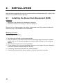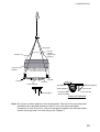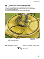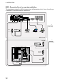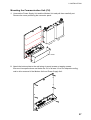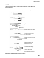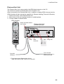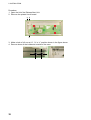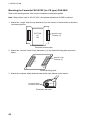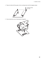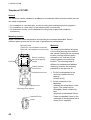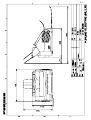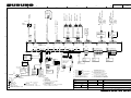
1
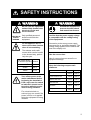
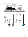
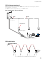
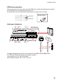
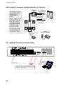
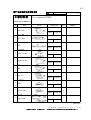
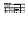
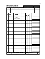
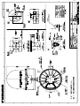
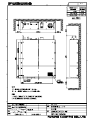
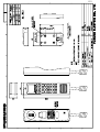
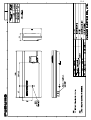
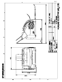
INMARSAT FLEET F77
SHIP EARTH STATION
FELCOM 70
PRINTED IN JAPAN
SAFETY INSTRUCTIONS
WARNING
WARNING
Do not open the equipment
unless totally familiar with
electrical circuits and
service manual.
ELECTRICAL Only qualified personnel
should work inside the
SHOCK
equipment.
HAZARD
Ground the equipment to
prevent electrical shock
and mutual interference.
Confirm that the power supply voltage
is compatible with the voltage rating
of the equipment.
Do not approach the radome closer than 4 meters
when it is transmitting.
Connection to the wrong power supply
can cause fire or equipment damage. The
voltage rating appears on the label at the
rear of the display unit.
The radome emits radio
waves which can be harmful
to the human body, particularly the eyes.
Use the correct fuse.
RF power density
on antenna aperture distance
100W/m2
2
2.0 m
2
4.0 m
25W/m
10W/m
nil
Turn off the power at the
mains switchboard before
beginning the installation.
Post a sign near the switch
to indicate it should not be
turned on while the equipment is being installed.
Use of a wrong fuse can cause fire or
equipment damage.
Keep the following compass safe
distances.
Standard Steering
Antenna Unit
0.65 m
0.30 m
Communication Unit
1.00 m
0.60 m
Distress Alert Unit
0.30 m
0.30 m
ISDN Handset
1.00 m
0.65 m
Facsimile
1.30 m
0.80 m
Telephone
0.50 m
0.40 m
Fire, electrical shock or
serious injury can result if the
power is left on or is applied
while the eqiuipment is being
installed.
i
TABLE OF CONTENTS
SYSTEM CONFIGURATION................................................................................ iii
EQUIPMENT LISTS ............................................................................................. iv
1. PLANNING ....................................................................................................... 1
1.1
1.2
1.3
1.4
1.5
1.6
1.7
1.8
1.9
Placing the antenna unit................................................................................................1
Designing antenna mast................................................................................................3
Physical characteristics of units.....................................................................................6
CU connectors ..............................................................................................................8
Example of installation.................................................................................................10
Placing units................................................................................................................12
Grounding considerations............................................................................................14
Laying cables ..............................................................................................................16
Telephone wiring .........................................................................................................17
2. INSTALLATION .............................................................................................. 18
2.1
2.2
2.3
2.4
Installing the Above Deck Equipment (ADE)................................................................18
Connecting antenna cable to ADE...............................................................................21
Installing the Below Deck Equipment (BDE) ................................................................23
Installing option units ...................................................................................................34
PACKING LISTS
OUTLINE DRAWING
INTERCONNECTION DIAGRAM
ii
G3 FAX
FC755D1
(Japanese)
Incoming
Indicator
Adapter
ISDN
Wall Socket
102176
FAX-8070P/3850
220VAC
ANALOGUE
WALL SOCKET
(OP16-11)
Analogue
Telephone
MJ-2S
ISDN
Wall Socket
102176
DBAR104001/888
SF-870
ISDN Handset
Connection Box
QUFC911918
Incoming
Indicator
FC755D1
(Japanese)
Analogue- to ISDN TA
QDGY911912
TA
CO-SPEVV-SB-C 0.2x1P
(10/20/30/40m)
TTYCY-1 or
CO-SPEVV-SB-C 0.2x1P
(10/20/30/40m)
TTYCY-1 or
CO-SPEVV-SB-C 0.2x1P
(10/20/30/40m)
SF-370
Distress Alert
Unit
M12
16S0116-0
M12
GND
100-240V AC
φ1, 50-60Hz
AC IN
RS232
RS232
RS232C Cable
RS232C Cable
(M)
*Total Number of ISDN : Max 8 (include TA)
Tel 4 (2W)
Tel 3 (2W)
USB
NMEA-0183(4W)
ISDN4
Tel 2 (2W)
Tel 1 (2W)
20- 60m : N-P8DFB
60-100m : N-P12DSFA
8D-FB- CV "30M" 20S0021-0
8D-FB- CV "50M" 20S0022-0
12D-SFA-CV "100M" 16S0211-0
Communication unit
SF-270
SIM CARD
ISDN 3
ISDN 2
ISDN 1
SF-170 : Mast mounted
radome
SF-171 : Desk mounted
radome
20- 60m : N-P8DFB
60-100m : N-P12DSFA
GPS
ANTENNA UNIT
SF-170
SF-171
Broad Band output (BRO)
(15m Max)
103776
SF-870
SF-870
Distress Alert
Unit
SF-370
ISDN Handset
standard supply
ISDN Handset
optional supply
RS232-USB
converter
TTYCY-1 or
CO-SPEVV-SB-C 0.2x1P
(10/20/30/40m)
ISDN Cable
TTYCY-1 or
CO-SPEVV-SB-C 0.2x1P
(10/20/30/40m)
PC or Data
Equipment
Gyro/GPS
(not requipment)
G4 FAX
ISDN telephone
Ship's Analogue
PABX
external equipment
(user supply)
SYSTEM CONFIGURATION
iii
EQUIPMENT LISTS
Standard Supply
Name
Antenna Unit
Type
SF-171
Code No.
Qty
-
1
Remarks
SF-170
Communication Unit
SF-270
-
1
ISDN Handset
SF-870
-
1
Distress Alert Unit
SF-370
-
1
Installation Materials
CP16-02800
000-043-251
1
Power cable for communication unit
CP16-02701
004-446-480
1
for antenna unit
CP16-02700
000-043-209
CP16-02710
000-043-210
CP16-02720
000-043-219
Spare Parts
Accessories
iv
Cable 8D-FB-CV (30m), CP16-02702
1
Cable 8D-FB-CV (50m), CP16-02702
Cable 12D-SFA-CV (100m), CP16-02703
CP16-02900
000-043-445
1
Signal cable for Distress alert unit
SP16-01501
004-446-470
1
for antenna unit
SP16-01601
004-447-160
1
Fuses for communication unit
FP16-00800
000-043-356
1
for ISDN handset
FP16-03000
000-043-466
1
CD-ROM for communication unit
EQUIPMENT LISTS
Optional Supply
Name
Type
Code No.
Qty
Remarks
Facsimile
FAX-8070P
-
1 set
For CE type, w/CP16-02601
FAX-2850
-
w/CP16-02601
MFC-4800J
-
Japanese version
Drum Unit
DR-10J
000-146-598
1
For above Facsimile
Toner Cartridge
TN-10J
000-146-599
1
For above Facsimile
Telephone
FC755D1
Antenna Cover
QB05-1801
100-079-480
1
Modular Jack Box
OP16-10
000-043-278
1
Box type
OP16-11
000-043-279
1
Flush mount type
Modular Jack Set
OP16-13
000-043-228
1
Lifting Metal
OP16-15
004-442-460
1
2-pair cable
CO-SPEVV-SB-C
0.2x2P
000-120-792
1
1-pair cable
CO-SPEVV-SB-C
0.2x1P
-
1 set
w/CP16-00511, 00512
For ISDN connection, 10m
000-120-794
For ISDN connection, 20m
000-120-214
For ISDN connection, 30m
000-132-827
For ISDN connection, 40m
000-132-826
For ISDN connection, 50m
000-110-681
1
For Analog Telephone, 10m
000-138-789
For Analog Telephone, 20m
000-138-790
For Analog Telephone, 30m
000-138-791
For Analog Telephone, 40m
000-138-792
For Analog Telephone, 50m
Transformer
0P16-25
004-446-850
1
Analogue Telephone
DBAR
104001/888
000-147-693
1
Terminal Adapter
QDGY911912
000-147-698
1
ISDN Wall Socket
102176
000-147-699
1
ISDN Handset
SF-870
000-043-252
1
Connection Box
QUFC911918
000-147-700
1
Distress Alert Unit
SF-370
Incoming Indicator
KK-893-3977
Transformer
SD-221
000-148-478
-
Transformer E-300+cable
100VAC→220VAC (300VA)
For FAX-2850 or FAX-8070P
1
1
For analogue telephone line
1
For facsimile MFC-4800J
v
1.
PLANNING
1.1
Placing the antenna unit
General
FELCOM 70 is delivered either with mast mounted or deck mounted radome. The mast
mounted version includes a hatch which provides access for service and repair, whereas
the deck mounted version must be lifted down. Interfering objects (especially metallic
objects such as masts) near the antenna can, in the worst case, prevent reception or
transmission. Further, RF radiation from the antenna will affect the human body. Keep these
and the following guidelines in mind when selecting a mounting location for the antenna
unit.
Secure unobstructed path in all directions
The ideal mounting location secures an unobstructed path between the antenna unit and
the satellites, from horizontal to zenith. In order words, whatever the direction the antenna
unit is pointing there are no interfering objects within the main beam (16 degrees). While
this might be feasible on some vessels, on others it is impossible due to space
considerations. The antenna unit should be located at least 3 meters away from masts
having a diameter less than 15 centimeters.
Select a location low in vibration
The maximum permissible vibration amplitude in three axis direction should be as shown in
the table at the top of the next page. Consult with the shipyard to determine the mounting
location which meets the requirements shown in the table.
The table at the top of the next page is taken from Inmarsat’s System Definition Manual
(SDM) and defines frequency and maximum vibration amplitude.
Freq. Range
4 to 10 Hz
10 to 15 Hz
15 to 25 Hz
25 to 33 Hz
Max. Amplitude
2.54 mm (max. 9.8 m/s²)
0.76 mm (max. 6.86 m/s²)
0.40 mm (max. 9.8 m/s²)
0.23 mm (max. 9.8 m/s²)
Half Vibration
Max. amplitudes
1
1. PLANNING
Locate away from passengers and crew
Radio waves can be harmful to the human body. Since safe distances vary by country and
ship construction there is no uniform formula for calculating safe distance. However, below
are general guidelines.
! Personnel should not approach an area in which the radiation level is higher than 10 W/m2,
i.e., within 4 m from the radome surface.
WARNING
Do not approatch within 4 meters of the
antenna radome when it is transmiting.
Microwave radiation can be harmful to
the human body, particularly the eyes.
Construct a protection fence around the antenna unit in order that personnel can not
approach the antenna unit within 4 m. Also, to alert personnel not to approach the antenna
unit, attach the caution labels (supplied as installation materials) to any bulkhead which is at
the position of 4 m from the antenna unit.
MICROWAVE RADIATION !
NO ADMITANCE WITHIN 4m
4m
4m
Minimum distance from other antennas
HF antennas, communication/navigation antennas:
The FELCOM 70 antenna should be at least 5 meters from a HF antenna. VHF, satellite
navigation antenna and other communication antennas should be at least 4 meters away.
Radar:
The FELCOM 70 antenna should be at least 5 meters away to protect the low noise
amplifier in the radar antenna. However, if this distance cannot be secured be sure the
FELCOM 70 antenna unit is not within the radar beam.
2
1. PLANNING
More than 5 m
30
20
If installed within 5 m of
radar antenna, the antenna
unit must not be within the
radar beam.
Distance from antenna radar
Compass safe distance
Locating the antenna unit too close to a compass can affect compass performance. The
compass safe distance is 0.65 meters, steering compass, 0.30 meters, standard compass.
Other mounting guidelines
Other important mounting guidelines are
• Locate the antenna unit away from exhaust stacks (foreign material on the radome can
interfere with reception and transmission).
• Keep the unit away from heat sources.
• Locate the unit away from places where fuels and chemical solvents are stored.
• Keep in mind the length of the cable from the communication unit is maximum 100 meters.
1.2
Designing antenna mast
General
To facilitate servicing, construct a mast more than 1 meter in height from the deck. The
paragraphs which follow provide guidelines for selection and construction of the mast.
Refer to the drawing at back of this manual.
Guardrail, platform
When the mast is tall, fit it with a guardrail and platform (or steps), for serviceman’s safety
and convenience.
For servicing ease, the distance between hatch and the deck (or platform) to the antenna
unit should be about 1 meter. (In most installations the serviceman stands on the platform
while checking the radome. Thus this distance should be secured for ease of servicing.)
The guardrail should be as high as possible for sufficient safety.
3
1. PLANNING
Mast strength
The mast material must be sufficiently strong to meet the demands of the marine
environment. It should satisfy the following requirements.
• It must be able to support radome mass plus at least 2.5 cm of ice and snow. Special
consideration should be given if the unit is operated in areas of heavy snow or freezing
temperature.
• Mast bending moment must be able to withstand expected maximum pitching, rolling and
wind pressure.
To prevent resonance at low frequencies (about 5 Hz), four stays can be fixed between the
mast and the mounting base.
Wind
Pressure
Mass
Mast
Bending
Moment
Fixing radome
Item
Antenna unit mass
Mass
65 kg ± 10%
Platform, guardrail mass
Expected ice and snow
Maximum wind pressure (at wind speed 75 m/s)
2080 N
Maximum bending moment (at wind speed 75 m/s)
1248 N•m
Maximum bending moment
1440 N•m
(at wind speed 75 m/s, rolling angle 30 degrees)
Maximum bending moment
(at wind speed 75 m/s, rolling angle 30 degrees including 0.5 G speed added by
rolling.)
4
1630 N•m
1. PLANNING
Mounting base
A mounting base is installed between the mast and the antenna unit. Below are guidelines
for installation of the mounting base.
1. The face of the mounting base should be flat as possible (tolerance: within 2 millimeters
of the horizontal plane).
2. The mounting base should be parallel with ship’s horizontal plane (tolerance: ±1
degree).
3. The fixing bolts of the mounting base should be parallel with the ship’s keel line
(tolerance: ±2 degrees).
4. Weld a ground bolt (stainless steel, M10x40, local supply) to the mast within 50 cm of
the ground terminal on the antenna unit. The length of the ground wire (supplied) is 50
cm.
5. Make four holes on the mounting base to face drain holes of the antenna unit.
Fixing holes
Drain holes
Mounting base
Mounting base
5
1. PLANNING
1.3
Physical characteristics of units
Communication Unit (CU)
322.5
mm
25
165
380mm
165
Dia 6mm
25
85mm
25
25
273
Mass: 7 kg
Handset holder/cradle
ISDN Handset
(for ISDN Handset)
22 mm
54 mm
DIAL 00+INTL
TEL NO+
SHIFT BAT
ALPHA
ON
ALPHA
MORE/
HELP
ENTER
198 mm
FUNC
SHIFT
LES
PTT
ON/OFF
LIST
ESC
1
DEL
2
DEF
4
JKL
5
MNO
7
STU
8
VWX
0
ÄÖÜ
ABC
DATA
ØÁ.
PLAY
TAX
LIST
3
GHI
6
PQR
9
YZÆ
LIGHT
22.5
37.5
SPC
34
mm
100 mm
2000 mm
40
15
60 mm
RJ45
Mass: 0.3 kg
Mass: 0.06 kg
45
35
mm
230 mm
89 mm
Distress Alert Unit
45
57
Mass: 0.24 kg
6
116
57
30
15
1. PLANNING
ISDN wall socket
(option)
Connection box
(option)
82
m
m
50 170 mm
mm
30 mm
70
mm
200 mm
Incoming indicator
(option)
20
64
mm
125
27 mm
20
m
85
m
20
160
20
Mass: 0.6 kg
Terminal Adapter
(option)
m
4m
14
30 mm
13
6m
m
7
1. PLANNING
1.4
CU connectors
Upper connector panel
POWER
INDICATOR
ON/OFF SWITCH
FUSES
100-240 VAC
O
I
SIM CARD
BROADBAND
RF
(DGPS)
SIM CARD INSIDE
WHEN CHANGING MODEM UNIT
REMOVE COVER
AND TAKE OUT SIM CARD
100-240 AC MAINS
CONNECTOR
SIM CARD
(inside cover)
L-BAND
OUTPUT
ANTENNA
CONNECTOR
For lower panel,
see next page
8
1. PLANNING
Lower connector panel
RS-422:
serial port for
connection of
data equipment
with up to 100
metres cables.
ISDN
TX
RX
RX
TX
RX
RX
RX
RX
TX
RX
RX
TX
TX
ISDN
TX
TEL 3
TEL 4
TX
TEL 1
TEL 2
RS-422
ISDN
TX
NMEA
NMEA
RX
IND
TX
TX
SW
SILENCE
RX
Screw terminal blocks TEL 1 - 4, and
RJ45 connectors TEL 3 - 4:
Connection of 2W analogue telephones and
G3 fax
ISDN ISDN TEL 4
ISDN ISDN TEL 3
USB
ISDN
ISDN:
Connectors/RJ45
Services:
• 4.8 kbps compressed speech
• 64 kbps speech
• 64 kbps data service (UDI)
• 56 kbps data service (V110)
• 64 kbps audio service (3.1 kHz)
USB:
serial data port for:
• operation and configuration
from PC.
• 64 kbps data service (UDI)
• MPDS
Note! Use shielded ISDN cable
RS-232:
9-pin serial data ports for:
• operation and
configuration from PC.
• software download
• 64 kbps data service (UDI)
• MPDS
RS-232
B
RS-232
A
9
1. PLANNING
1.5
Example of installation
RF Cable
to/from
Antenna
Analogu
e tel/fax
Commun
ication
Unit
ISDN
Handset
Distress
Alert Unit
ISDN bus
DIAL 00+INTL
TEL.NO.+
SHIFT
ON
DEL
1
2
3
4
5
6
7
8
9
0
Telef
ax
Groun
d foil
Rem
ote
insta
PC
llatio
ns
Distr
Alertess
Unit ISDN
Hand
set
Rem
ote
insta
llatio
DIAL
00+IN
TEL.N
'
O.+ TL
SHIFT
ON
DEL
1
4
7
2
5
8
0
10
3
6
9
Ana
Telelogue
phon
e
ns
1. PLANNING
Example of cabling arrangement
The installation includes five ISDN Handsets (two w/Distress Alert Unit), Group 3 and 4
telefaxes, PC w/printer, Data Equipment and two Analogue Telephones.
TX
RX
RX
RX
RX
RX
TX
ISDN
TX
RX
TX
TX
TX
RX
TX
ISDN
TX
TEL 1
TEL 3
TEL 4
RS-422
ISDN
RX
NMEA
RX
IND
NMEA
TX
RX
SW
TX
TEL 2
CU CONNECTOR PANEL
SILENCE
ISDN ISDN TEL 4
ISDN ISDN TEL 3
USB
RS-232
B
ISDN
RS-232
A
RS232-USB
converter*
DIAL 00+INTL
TEL. NO.+
SHIFT BAT
ALPHA
ON
ISDN
Handset
FUNC
ALPHA
SHIFT
MORE/
HELP
ON/OFF
ESC
1
DEL
ABC
2
4
JKL
5
MNO
7
STU
8
VWX
0
ÄÖÜ
DATA
ØÁ.
PLAY
DEF
TAX
Distress Alert Unit
ENTER
LES
PTT
LIST
LIST
3
GHI
6
PQR
9
YZÆ
LIGHT
Analogue
telefax (G3)
SPC
PC
PC
Digital
telefax (G4)
Connection Box
QUFC 911 918
Radio Room
DIAL 00+INTL
TEL.NO.+
SHIFT BAT
ALPHA
ON
FUNC
SHIFT
ALPHA
MORE/
HELP
ENTER
LES
PTT
ON/OFF
LIST
ISDN
Handset
ESC
1
DEL
2
DEF
4
JKL
5
MNO
7
STU
8
VWX
0
ÄÖÜ
ABC
DATA
ØÁ.
PLAY
TAX
LIST
3
GHI
6
PQR
9
YZÆ
LIGHT
SPC
ISDN
Handset
SHIFT BAT
ALPHA
ON
FUNC
SHIFT
Distress Alert Unit
,
SHIFT BAT
ALPHA
ON
FUNC
SHIFT
ALPHA
MORE/
HELP
ENTER
Analogue
telephone
ALPHA
MORE/
HELP
ENTER
LES
PTT
ON/OFF
LIST
ESC
1
DIAL 00+INTL
TEL.NO.+
Digital
telefax (G4)
DIAL 00+INTL
TEL.NO.+
ABC
DEL
2
PLAY
%
DEF
4
JKL
(5
MNO
7
STU
)8
*VWX
+
0
,ÄÖÜ
- .
DATA
ØÁ.
TAX
LIST
3
!GHI
"6
PQR
#
$
9
%&
YZÆ
'
LIGHT
!
SPC
LES
PTT
ON/OFF
LIST
ESC
DEL
LIST
1
ABC
2
DEF
3
4
JKL
5
MNO
6
PQR
7
STU
8
VWX
9
YZÆ
0
ÄÖÜ
DATA
ØÁ.
PLAY
TAX
GHI
LIGHT
SPC
ISDN
ISDN Handset
Saloon
Bridge
DIAL 00+INTL
TEL.NO.+
SHIFT BAT
ALPHA
ON
ISDN
Handset
Analogue
telephone
FUNC
SHIFT
ALPHA
MORE/
HELP
ENTER
PC
LES
PTT
ON/OFF
LIST
ESC
DEL
LIST
1
ABC
2
DEF
3
GHI
!
4
JKL
5
(
MNO
"6
PQR
#
8
)
VWX
*
$
9
YZÆ
%&'
0
+
ÄÖÜ
, - .
7
STU
DATA
ØÁ.
PLAY
%
TAX
LIGHT
!
SPC
ISDN
Owner's Cabin
Captain's Cabin
*: Recommended RS232-USB Converter : USB-RSAQ2 by I-O DEVICE INC.
11
1. PLANNING
1.6
Placing units
Placing the Communication Unit (CU)
The Communication Unit should be placed in a ventilated area. To ensure adequate cooling
of the CU a 10 cm unobstructed space must be maintained above and below the unit.
A space of 10 cm above the CU is also required to allow removal of units.
For grounding, see "1.7 Grounding considerations" on page 14 and "Location and
grounding of units" on page 23.
Ambient temperature range 0° - 45°C.
The CU is manufactured as a cabinet for wall or desktop installation with dimensions as
shown. Six holes through the CU mounting plate allows the unit to be secured to the wall or
desk top.
10 cm
free
space
322.5
mm
380mm
10 cm
free
space
85 mm
Placing the Distress Alert Unit & ISDN Handset
The Distress Alert Unit is operated in conjunction with an ISDN Handset.
The ISDN Handset functions as a display and communication unit for alert transmission.
It may also be used for normal voice communication.
Up to two (2) Distress Alert Units & ISDN Handsets may be connected in series. The units
may be installed anywhere onboard the vessel.
Four separate ISDN ports are available on the CU as RJ45 jacks or screw terminal blocks.
Max cable length: 100 m, 4 x 0.22 mm2 .
See "ISDN telephones/equipment" on page 34.
DIAL 00+IN
TEL.NO.+ TL
ON
FUNC
SHIFT
ALPHA
SHIFT BAT
ALPHA
ENTER
MORE/
HELP
LES
PTT
ON/OFF
LIST
ESC
1
4
7
ABC
JKL
STU
DATA
ØÁ.
12
DEL
2
5
PLAY
DEF
MNO
8
VWX
0
ÄÖÜ
TAX
LIST
3
GHI
6
PQR
9
YZÆ
LIGHT
SPC
1. PLANNING
Placing the ISDN Handset as a standard telephone
The ISDN Handsets may be installed as standard telephones. The units may be installed
anywhere onboard the vessel.
Four separate ISDN ports are available on the CU as RJ45 jacks or screw terminal blocks.
DIAL 00+IN
TEL.NO.+ TL
ON
FUNC
SHIFT
ALPHA
SHIFT BAT
ALPHA
ENTER
MORE/
HELP
LES
PTT
ON/OFF
LIST
ESC
1
4
7
ABC
JKL
STU
DATA
ØÁ.
DEL
2
PLAY
DEF
*5
MNO
+8
,VWX
- .
/0
0ÄÖÜ
12
TAX
.
LIST
3
GHI
#6
PQR
$
9
%
LIGHT
"
YZÆ
&'
(
SPC
Placing the telefax (option)
A digital telefax (Group 4) can be connected to one of the ISDN outlets, or to an ISDN bus
for transfer at 64 kbps rate.
An analogue telefax (Group 3) should be connected to the FAX (GR3) outlet, providing up
to 28.8 kbps transfer speed.
Placing the PC (user supply)
A PC w/ISDN card can be connected to one of the ISDN outlets, or to an ISDN bus for 64
kbps rate data communication for installation up to 100 m away from the CU.
With the PC connected to the USB/RS-232/RS-422 port it can also be used for control and
configuration of the Communication Unit.
This requires that the vtLite Marine program accessible on the FELCOM 70 CD is installed.
Connection to the USB/RS-232/RS-422 port also allows 64 kbps data transmission.
See the User Manual.
Cable lengths:
• ISDN port:
• USB port:
• RS-232 ports:
• RS-422 port:
See "ISDN telephones/equipment" on page 34.
3m
3m
100 m
13
1. PLANNING
Placing analogue telephones (option)
Analogue 2-wire telephones can be installed anywhere onboard the vessel.
Four separate analogue ports TEL1-TEL3 and FAX (GR.3) are available on the CU.
TEL3 and FAX (Gr.3) are in addition available as RJ45 jacks.
The analogue telephone DBAR 104001/888 (option) should be installed on a bulkhead.
UP
1.7
Grounding considerations
A successful installation of a maritime satellite terminal must take into account the noisy
environment in which the equipment shall operate.
Electrical noise
The electrical environment on board a ship is usually quite noisy.
Powerful electrical installations cause voltage variations and transients, as well as low and
high frequency noise. Radio and radar equipment radiate radio frequency signals which
frequently impregnate cables on board with unwanted interference.
Ground plane
Most ships have a steel hull. One should think that the steel construction of the ship would
constitute a good ground plane.
This is often not quite true. Rust, other forms of corrosion, paint and grease, often prevent a
good ground connection. A consequence of this is that high energy power distribution on
board a ship can cause significant ground potential differences.
Antenna unit
Adequate grounding of the Antenna Unit depends on the fastening bolts making
good contact with the top flange of the mast. This is obtained by removing paint and
using enclosed toothed washers and nuts.
Antenna cable
The antenna coaxial cable normally has a solid or meshed metal screen which must be
terminated to ground both at the antenna pedestal and at the CU. The length of the cable
can often be more than 40 metres. If the ground potential level at the two points differ, the
current passing through the screen of the coaxial cable can be quite strong. The antenna
cable screen constitutes a heavy gauge wire, which is capable of conducting large amounts
of current.
14
1. PLANNING
Below Deck Equipment
The CU must be provided with a good electrical connection to the ship's hull for grounding.
This is obtained by using copper foil. (See Installation: "Location and grounding of units"
on page 23.)
Length of copper foil/10 cm should not exceed 300 cm. The foil should be connected to
ship's hull (deck or roof) by hard-soldering (or screws) to steel.
Mains power/ground
Mains ground is secured to the common grounding point through the external supply. It is
therefore important to use the same mains branch for additional equipment connected to
the CU (Fax, PC w/printer etc.).
Location of the Below Deck Unit for best possible grounding.
See also INSTALLATION: "Location and grounding of Units" on page 23.
CU
min.
10 cm
Desktop
max. 3m
15
1. PLANNING
1.8
Laying cables
General
The coaxial cable for connection between the CU and the Antenna Unit should, if possible,
be laid before the equipment arrives. Make sure sufficient length of cable is ordered.
Where exposed to mechanical wear (on deck, through bulkheads etc.), the cable should be
protected by steel pipes.
Standard procedures should otherwise be followed for cabling in ship installations.
Special attention to existing safety regulations is required if the cable passes through zones
where there may be flammable or explosive gases. Use suitable gasproof cable glands or
bushings.
At the Antenna Unit
A free end of approximately 1.5 m of the antenna cable above the radome bottom should be
provided for connection to the coaxial connector in accordance with the installation
instructions in "Connecting the antenna cable to the CU" on page 28.
At the Communication Unit
The coaxial cable from the Antenna Unit should be given a free end of approximately 0.5 m
at the CU location.
ISDN Telephone, Distress Alert Unit, telefax or analogue telephone
Choose the position for the required wall sockets and lay the cables leaving a free end of
0.5 m. Also allow a free end of 0.5 m at the Connection Box.
16
1. PLANNING
1.9
Telephone wiring
Distress Alert Unit
.
1234
5678
12345678
RJ45
ISDN
Handset
DIAL 00+INTL
TEL. NO.+
SHIFT BAT
ALPHA
ON
FUNC
ALPHA
ENTER
SHIFT
MORE/
HELP
LES
PTT
ON/OFF
LIST
LIST
DEL
ESC
1
ABC
2
4
JKL
7
STU
DATA
ØÁ.
DEF
3
GHI
5
MNO
6
PQR
8
VWX
9
YZÆ
0
ÄÖÜ
PLAY
TAX
LIGHT
SPC
CU
connector
panel
DISTRESS
BUTTON
1
1
2
RX+ 3
TX+ 4
2
3
RX+
4
TX+
TX- 5
RX- 6
5
7
8
7
8
ISDN
(terminal)
block)
TB1
1
2
TX- 3
RX- 4
6
ALARM
BUZZER
TB2
1
2
TX- 3
RX- 4
4
5
3
6
TX+
TXRX+
RX-
RX+
TX+
To next
Distress Alert Unit
or ISDN wall
socket
ISDN
(RJ45
connector)
1234
5678
ISDN
Handset
DIAL 00+INTL
TEL. NO.+
RX+
SHIFT BAT
ALPHA
ON
FUNC
ALPHA
ENTER
MORE/
HELP
SHIFT
LES
PTT
ON/OFF
TX+
LIST
LIST
DEL
ESC
1
ABC
2
DEF
3
GHI
4
JKL
5
MNO
6
PQR
7
STU
8
VWX
9
YZÆ
0
ÄÖÜ
DATA
ØÁ.
PLAY
TAX
TX-
LIGHT
SPC
RX-
1
2
3
4
5
6
7
8
1234
5678
12345678
1
2
3
4
5
6
7
8
3
4
5
6
1
2
RX+
3
TX+
4
TX5
RX6
7
8
12345678
1
2
3
4
5
6
7
8
ISDN WALL
SOCKET
RJ45
connecor
1234
5678
Analogue
telephone
1
2
4
5
7
8
P
3
6
9
0
#
S
Re
1
2
3
4
5
6
7
8
12345678
1
2
3
4
5
6
7
8
CONNECTION
BOX
RJ45
1234
5678
1
2
3
4
5
6
7
8
FAX/TEL3
(RJ45
connector)
12345678
1
2
3
4
5
6
7
8
TEL1-3
(terminal
block)
17
2.
INSTALLATION
Open all boxes supplied and check the contents with the enclosed packing list. Inspect units
and parts for possible transport damage.
2.1
Installing the Above Deck Equipment (ADE)
Unpacking
•
•
Check that if the antenna unit is damaged by shipment.
Unpack the antenna unit carefully so as not to damage it.
Remove hex nut, spring washer, flat washer, large washer and fixing material to dismount
the antenna unit. This hardware can be discarded.
Mounting procedure
See next page for illustration
1. Run lifting rope through eye bolts and shackles.
2. Cover the portion of the radome which contacts the lifting rope with protective material
(rubber mat, etc.), to prevent damage to the radome when hoisting it to the mounting
location.
3. Hoist the antenna unit to the mounting location.
4. Fix the antenna unit to the mounting base (see note on next page) with nuts, keeping in
mind hatch direction (standard direction is stern).
5. If necessary, replace eye bolts with hex. bolts (supplied).
6. Coat all bolts and nuts with silicone sealant to prevent electrolytic corrosion.
18
2. INSTALLATION
Lifting Rope
(Can be
supplied
together with
snackles.)
Radome
Protective
Material
Shackle
Eye Bolt
Eye Bolt
Antenna Bottom
Flat Washer
Mounting Base
Spring Washer
Mounting Base
10 mm Nut
Coat here with
silicone sealant.
13 mm Nut
FIXING OF RADOME
Note: Do not use a rubber gasket on the mounting base. The face of the mounting base
should be flat as possible (tolerance: within 2 mm of the horizontal plane).
If tolerance is more than 2 mm, insert a metal spacer between the antenna bottom
and the mounting base. For earth wiring, see Chapter 2.
19
2. INSTALLATION
Attach electromagnetic wave caution label
The label which warn of electromagnetic waves is supplied with the installation materials.
Attach it, considering to the following points.
• To the radome mast where it can easily be seen.
• In a conspicuous location in the stairwell leading to the deck where the antenna unit is
installed.
Removing ropes
The stabilizer in the radome is tied by the rope and shock-absorbing material to prevent
damage to it during shipment and installation. Cut and remove them after finishing the
installation.
B
Rope
B
Shock-absorbing material
20
2. INSTALLATION
2.2
Connecting antenna cable to ADE
ADE - Connecting antenna cable to Mast Mounted Antenna
1
2
3
Lead in the antenna cable 1100 mm from the cable entry in the antenna base.
Fix the cable with cable clamp.
Connect the coaxial connector and secure it by the cable gland.
Connection the antenna
cable in here.
Cable gland
Fasten the cable with cable-tip.
= D x10 , where as “D” is a diameter of coaxial cable.
Note: Bending radius “R” can be R >
D
R
R >
= D x10
21
2. INSTALLATION
ADE - Connecting coaxial cable to Deck Mounted Antenna
Deck mounted antenna unit is under development.
22
2. INSTALLATION
2.3
Installing the Below Deck Equipment (BDE)
Location and grounding of units
To next Distress Alert Unit & ISDN Handset
Antenna Cable
Communication Unit
Distress Alert Unit
ISDN Handset
ISDN
ALPHA
May 01
09:15
4.8 Speech
Mains
*1
Desktop
Common ground
Bolt M10
(cut to suitable length)
Angle
bracket
Nut M10
Lock washer
M10
Washer M10
Nut M10
Copper
foil
Wood etc.
Bulkhead
(iron)
Alternative
method:
brazing
solder
*1: If the AC plug is not mated to a ship's jack, cut the plug and connect to the ship's mains, using a junction
box (shipyard supply).
23
2. INSTALLATION
BDE - Example of local or near-by installation
The installation includes five ISDN Handsets (two w/Distress Alert Unit), Group 3 and Group
4 telefaxes, PC and two analogue telephones.
ISDN
TX
RX
RX
TX
RX
RX
RX
RX
TX
RX
RX
TX
TX
ISDN
TX
TEL-4
TX
TEL 1
TEL 3
TEL 2
RS-422
ISDN
TX
NMEA
NMEA
TX
RX
SW
IND
TX
RX
CU CONNECTOR PANEL
SILENCE
ISDN ISDN TEL 4
ISDN ISDN TEL 3
USB
ISDN
RS-232
B
RS-232
A
*1
(Next page)
DIAL 00+INTL
TEL. NO.+
SHIFT BAT
ALPHA
ON
FUNC
SHIFT
ISDN
Handset
ALPHA
MORE/
HELP
ON/OFF
ESC
DEL
ENTER
LES
PTT
LIST
LIST
1
ABC
2
DEF
3
4
JKL
5
MNO
6
PQR
7
STU
8
VWX
9
YZÆ
0
ÄÖÜ
DATA
ØÁ.
PLAY
TAX
GHI
LIGHT
SPC
Analogue
telefax (G3)
PC
PC
Radio Room
Bridge
DIAL 00+INTL
TEL.NO.+
SHIFT BAT
ALPHA
ON
FUNC
SHIFT
ALPHA
ENTER
MORE/
HELP
LES
PTT
ON/OFF
LIST
ESC
1
DEL
2
DEF
4
JKL
5
MNO
7
STU
8
VWX
0
ÄÖÜ
ABC
DATA
ØÁ.
PLAY
TAX
LIST
3
GHI
6
PQR
9
YZÆ
LIGHT
SPC
Connection Box QUFC 911 918
J1
1
1
ISDN Handset
8
J2
J3
9
10
J4
17
J5
Analogue
telephone
1
16
8
J6
#$
25
TB1
DIAL 00+INTL
TEL.NO.+
TB2
SHIFT BAT
ALPHA
ON
FUNC
SHIFT
ALPHA
MORE/
HELP
ENTER
LES
PTT
ON/OFF
LIST
ISDN
Handset
To
common
ground
24
J1 - J6: RJ45
w/grounded metal
housing
ESC
1
ABC
DEL
DEF
3
MNO
6
PQR
9
YZÆ
PLAY
4
JKL
5
7
STU
8
VWX
0
ÄÖÜ
DATA
ØÁ.
LIST
2
TAX
GHI
LIGHT
SPC
*2
(Next page)
2. INSTALLATION
BDE - Example of remote installation
The installation includes two ISDN Handsets connected to the ISDN bus via wallboxes with
two 8-pin RJ45 jacks and analogue telephone.
DIAL 00+INTL
TEL.NO.+
SHIFT BAT
ALPHA
ON
FUNC
SHIFT
PC
DIAL 00+INTL
TEL.NO.+
SHIFT BAT
ALPHA
ON
ISDN
Handset
FUNC
ALPHA
ENTER
SHIFT
MORE/
HELP
LES
PTT
ISDN
Handset
ON/OFF
LIST
ESC
1
DEL
2
DEF
4
JKL
5
MNO
7
STU
8
VWX
0
ÄÖÜ
ABC
DATA
ØÁ.
PLAY
TAX
LIST
3
ALPHA
MORE/
HELP
ENTER
LES
PTT
ON/OFF
LIST
ESC
DEL
LIST
1
ABC
2
DEF
3
4
JKL
5
MNO
6
PQR
7
STU
8
VWX
9
YZÆ
0
ÄÖÜ
DATA
ØÁ.
PLAY
TAX
GHI
Digital
telefax (G4)
LIGHT
SPC
GHI
6
PQR
9
YZÆ
LIGHT
SPC
ISDN
ISDN
*1
Saloon
Captain's Cabin
Analogue
telephone
*2
Owner's Cabin
ISDN Handset
The ISDN Handset is to be plugged into the ISDN socket located on the connector panel of
the CU, or to the Distress Alert Unit (if installed).
Note: It is not recommended to extend the handset cable by more than 6 m.
DIAL 00+IN
TEL.NO.+ TL
ON
FUNC
SHIFT
ALPHA
SHIFT BAT
ALPHA
ENTER
MORE/
HELP
LES
PTT
ON/OFF
LIST
ESC
DEL
LIST
1
ABC
2
DEF
3
4
JKL
5
MNO
6
PQR
8
VWX
9
YZÆ
0
ÄÖÜ
7
STU
DATA
ØÁ.
PLAY
TAX
GHI
LIGHT
SPC
25
2. INSTALLATION
Handset holder/cradle
The handset holder/cradle may be desk mounted or wall mounted.
Desk mounted
Wall mounted
Attach the holder to the wall or desktop with four 4 mm wood screws or tapping screws.
Place the Handset on the holder as shown.
click!
Hook ON magnet
26
2. INSTALLATION
Mounting the Communication Unit (CU)
1 Unscrew the Power Supply Unit and the Modem Unit and pull them carefully out.
Remove the cover protecting the connector panel.
ly
pp
u
rS
it
em
Un
we
Po nit
U
od
M
l
ne
a
rP
to
ec
n
on
C
Cover
2 Attach the bottom plate to the wall using six wood screws or tapping screws.
Ensure a free space above and below the CU of at least 10 cm for adequate cooling,
and to allow removal of the Modem Unit and Power Supply Unit.
27
2. INSTALLATION
3 Mount the Power Supply Unit and Modem Unit. Remount the connector panel cover
after connection of cables.
Connecting the antenna cable to the CU
1 Strip the Antenna coaxial cable leaving sufficient slack for connection to the CU.
2 Mount the N-plug on the cable in accordance with the instructions (see next pages).
DGPS
RF
N-P-8DFB
N-P-12DSFA
From Antenna unit
28
2. INSTALLATION
N-P-8DFB connector
Fabricate the antenna cable as shown below to connect the antenna cable to the
communication unit.
(Dimensions in millimeters.)
Outer Sheath
Armor
Inner Sheath Shield
30
50
Cover with heat-shrink tubing and heat.
Cut off insulator and core by 10 mm.
10
Twist shield end.
Slip on clamp nut,
gasket and clamp as shown left.
Clamp Nut
Gasket Clamp
(reddish
brown)
Aluminum Foil
Fold back shield over clamp and trim.
Trim shield here.
Insulator
Cut aluminum foil at four places,
90 from one onother.
Fold back aluminum foil onto shield
and trim.
Trim aluminum
tape foil here.
1
Expose the insulator by 1 mm.
5
Expose the core by 5 mm.
Pin
Clamp Nut
Shell
Solder through
the hole.
Slip the pin onto the conductor.
Solder them together through the
hole on the pin.
Insert the shell into the pin.
Screw the clamp nut into the shell.
(Tighten by turning the clamp nut.
Do not tighten by turning the shell.)
How to attach the antenna cable connector N-P-8DFB
29
2. INSTALLATION
N-P-12DSFA connector
(Dimensions in millimeters.)
Outer Sheath
Armor
Inner Sheath Shield
12
80
Remove outer sheath and armor by the
dimensions shown left.
Expose inner sheath and shield by the
dimensions shown left.
Twist shield end.
Slip on clamp nut, gasket and clamp
as shown left.
1.8
Expose the insulator by 1.8 mm.
4.5
Expose the core by 4.5 mm.
Pin
Clamp Nut
Shell
Solder through the hole.
Slip the pin onto the conductor.
Solder them together through the hole
on the pin.
Insert the shell into the pin.
Screw the clamp nut into the shell.
(Tighten by turning the clamp nut.
Do not tighten by turning the shell.)
How to attach the antenna cable connector N-P-12DSF
30
2. INSTALLATION
Distress Alert Unit
The Distress Alert Unit is connected to the ISDN bus/connector on the CU.
The maximum number of Distress Alert Unit is limited to two.
When connected to the Distress Alert Unit, in addition to regular ISDN voice service the
ISDN Handset will also include the capability for Distress handling (Transmit & Receive).
1. Remove the cover of the Distress Alert Unit.
2. Mount the unit with two topping screws to a suitable places.
3. Connect cables as shown below.
ISDN Handset
Clamp the shield section
of the cable.
Distress Alert Unit
w/cover removed
TB2
May 01
09:15
4.8 Speech
TB1
ALPHA
1 2 3 4
1 2 3 4
*1
Strap
RJ45
connector
From CU
ISDN port
TB1 = TB2
RX+ =
TX+ =
TX- =
RX- =
Fixing hole
1
2
3
4
To the second
Distress Alert Unit or
ISDN wall socket
*1 To connect second Distress Alert Unit or
ISDN wall socket, make a hole φ8 by using drill.
31
2. INSTALLATION
Procedure
1. Open the lid of the Distress Alert Unit.
2. Remove the printed circuit board.
a b
c
3. Make a hole of φ 8 mm at “a”, “b” or “c” position shown in the figure above.
4. Remove burrs at the inside and outside of the case.
32
2. INSTALLATION
Examples of Below Deck Equipment
%=
%=E
&=
&= E
RX
RX
&= E
TX
TX
TXE
%=
%=E
&=
RX
TEL 3
%$TEl 4
ISDN
RX
TEL 1
%$TEL 2
& -8 8
ISDN
%=
NMEA-
NMEA+
TX
RX
TX
<
SILENCE
RX
Communication Unit
ISDN
ISDN
TEL 3
ISDN
ISDN
TEL 4
USB
RS-232
B
RS-232
A
Distress
Alert Unit
ISDN
DIAL 00+INTL
TEL.NO.+
ISDN wall
socket
DIAL 00+INTL
TEL.NO.+
SHIFT BAT
ALPHA
SHIFT BAT
ALPHA
ON
ON
FUNC
FUNC
ALPHA
MORE/
HELP
ALPHA
ENTER
ENTER
SHIFT
SHIFT
LES
PTT
MORE/
HELP
LES
PTT
ON/OFF
ON/OFF
LIST
LIST
ESC
1
DEL
2
DEF
4
JKL
5
MNO
7
STU
8
VWX
ABC
PLAY
TAX
ESC
1
2
DEF
4
JKL
5
MNO
7
STU
8
VWX
0
ÄÖÜ
ABC
DATA
0
LIGHT
ØÁ.
ÄÖÜ
PLAY
LIST
3
GHI
GHI
PQR
YZÆ
DATA
ØÁ.
DEL
LIST
3
6
9
TAX
6
PQR
9
YZÆ
LIGHT
SPC
SPC
ISDN
Handset
Analogue
telephone
ISDN
Handset
Digital
telefax (G4)
PC w/ISDN
interface
Analogue
telefax (G3)
PC
33
2. INSTALLATION
2.4
Installing option units
Connection Box QUFC 911 918 (option)
Inside Connection Box
J1
1
1
8
J2
J3
9
J4
10
J5
17
1
16
8
J6
25
TB1
TB2
J1 - J6: RJ45
w/grounded
metal housing
Holes for fastening
cables with cable-tie.
Ground this Terminal to ship's body
with 2.5sq wire.
Note: Before installing the connection box, connect cables and fasten the cables with cable
ties.
Wiring
1
1
2
3
4
J1
J2
J3
9
J4
10
J5
1
2
17
16
GND
24
TB1
34
8
25
TB2
2. INSTALLATION
ISDN telephones/equipment
ISDN equipment is connected to the ISDN outlets on the CU connector panel, either to
terminal blocks or RJ45 jacks.
An ISDN bus can be connected to one of the ISDN outlets.
Max. extension length: 100 m, min. 0.22 mm2.
Screen
ISDN bus
Local equipment
ISDN wall socket
ISDN
ISDN
ISDN
Remote equipment
DIAL 00+INTL
TEL.NO.+
ON
FUNC
SHIFT
ALPHA
MORE/
HELP
SHIFT BAT
ALPHA
ENTER
LES
PTT
ON/OFF
LIST
ESC
1
1
DEL
LIST
ABC
2 DEF 3 GHI
4 JKL 5 MNO
6 PQR
7 STU 8 VWX
9 YZÆ
PLAY
TAX
DATA
ØÁ.
8
0 ÄÖÜ
LIGHT
SPC
'
RJ
45
Ma
x5
m
ISDN telephone, TA, telefax gr.4 or pc
ISDN cable lengths
CU
Total length of ISDN bus:
100 m
The last
ISDN wall
socket must
terminated,
see next
page
Up to 8 ISDN devices can be operated with FELCOM 70
35
2. INSTALLATION
ISDN
Part of CU connector panel
ISDN
connector
ISDN
equipment
1
ISDN
1
RX
2
2
a2
a1
b1
b2
RX+
TX+
TXRX-
12345678
123
3
4
5
6
7
8
ISDN ISDN TEL 4
RX
RX
TX
TX
RX
RX
TX
ISDN
RX
TX
RX
TX
TX
RX
TX
TEL 4
TX
ISDN
3
4
5
6
7
8
78
456
ISDN ISDN TEL 3
ISDN
RJ45
ISDN
ISDN wall socket
ISDN bus
from the CU
To next ISDN wall socket via
junction box, if required.
4 5 3 6
2 1
ON
RJ45 RJ45
8
36
1
8
1
When the distance between the
CU and the last connection box
on an ISDN bus exceeds 10m, the
termination resistors in the last box
must be incorporated by setting
both slide switches to position ON.
The switches in all other boxes
should be OFF (default setting).
The two RJ45 jacks are connected
in parallel.
N
(TX+ TX- RX+ RX-)
Signal 38VDC
TX+
TXRX+
+
RX+
1
Terminal Name
4
a1
5
b1
3
a2
6
b2
ISDN wall socket
2. INSTALLATION
ISDN bus termination
When longer than 10 metres, the end of the ISDN bus must be terminated by two resistors
as shown below. Only one bus/termination per CU.
Be aware that only one ISDN cable is permitted to be longer than 10 metres.
RX+
100 ohm
Alternative termination:
ISDN bus end plug
TX+
TX -
ND
100 ohm
S-E T
BU NO
E
DOMOV
E
R
RX -
Analogue telephones
TEL 4
RX
TX
RX
RX
RX
TX
TX
Part of the CU
connector panel
ISDN
ISDN
TX
TEL 3
TEL 1
TEL 1 TEL 3
ISDN ISDN TEL 4
12345678
TEL 2 TEL 4
RX
TX
RX
RX
ISDN
RX
TX
TX
TX
TEL 4
TEL 2
RS-422
RX
TX
RX
123
456
78
ISDN ISDN TEL 3
ISDN
TEL 3
CONNECTORS
TEL 3-4
RJ45
1
2
1
2
3
4
5
6
3
4
5
6
7
7
8
8
1
2
3
4
5
6
7
8
P
9
0
#
S
Re
Analogue telephones and G3 fax are connected to the TEL1 through TEL4 outlets.
For TEL3 and TEL4 RJ45 jacks are provided in parallel.
See diagrams for RJ11 pin configuration.
Max. extension length: 150 m, min. 0.22 mm2 .
37
2. INSTALLATION
Wall socket for analogue telephone/telefax gr.3 (option)
Connection
Box
The telephone and/or
telefax cable can be
terminated in a
modular jack, as
shown.
CU
Screw terminal blocks
TEL1 through TEL4
Alternative connection:
RJ45 jacks in parallel
with screw terminals
(TEL3 and TEL4)
Remove approx. 3 cm
of the jacket from the
cable end, strip off 1
cm of the insulation
from each core and
connect to centre
terminals 3 and 4.
Use the two
centre terminals.
Interchanging of the
wires at terminals 3
and 4 has no effect.
6
1
Remote
telephone or telfax
Use the two centre
terminals.
1
6
ISDN
TX
RX
RX
TX
RX
RX
RX
TX
RX
TX
TX
TX
RX
TX
TEL 3
TEL 4
ISDN
RX
TEL 1
ISDN
TX
NMEA
RX
RS-422
TEL 2
IND
TX
RX
TX
SW
SILENCE
NMEA
PC - asynchronous data communication
ISDN ISDN TEL 4
ISDN ISDN TEL 3
USB
ISDN
RS-232
B
RS-232
A
PC serial port
Max 100 metres
PC serial port
USB port
The driver used with the RS-232 B (DATA) port can
be switched to be used with the RS-422 (DATA) port
instead, see the User Manual.
38
DTE
2. INSTALLATION
RS-232 connector pin assignments
Pin
Mnenumber monic
Circuit DIN
CCITT Signal
circuit source
5 4 3 2 1
Dscription
1
CD
109
DCE
Carrier detect
2
RXD
BB
D1
104
DTE
Received Data
3
TXD
BA
D2
103
DCE
Tramsmitted Data
4
DTR
108
DTE
Data terminal ready
5
GND
102
6
DSR
107
DCE
Data set ready
7
RTS
CA
S2
105
DTE
Request To Send
8
CTS
CB
M2
106
DCE
Clear To Send
9
RI
125
DCE
Ring indicator
Signal ground
9 8 7 6
Signal source DTE means
that the signal goes from the
PC to FELCOM 70.
Signal source DCE means
that the signal goes from
FELCOM 70 to the PC.
Signal descriptions
102 Signal Ground
Digital ground, return line.
103 Send Data
Data transmitted from DTE (PC) to DCE (FELCOM 70).
104 Receive data
Data Received from DCE (FELCOM 70) to DTE (PC).
105 Request To Send
OFF requests DCE (FELCOM 70) to suspend transmission to DTE (PC).
ON requests DCE (FELCOM 70) to resume transmission to DTE (PC).
106 Clear to send
OFF indicates that DCE (FELCOM 70) cannot accept data from DTE (PC).
ON indicates that DCE (FELCOM 70) is prepared to accept data from DTE (PC).
107 Data Set Ready
Signal from FELCOM 70 that when ON indicates that a data call setup is in progress.
108 Data Terminal Ready
Signal from PC. This signal is used in the Hotline mode and indicate when going from OFF to ON that
the PC wants to make a data call. The PC clears the call by setting the signal from ON to OFF.
109 Receive Signal Indicator
Signal from FELCOM 70 that when ON indicates that connection is established and received data will be
delivered on circuit 104, Received Data.
125 Ring Indicator
Signal from FELCOM 70. This signal is used in the Auto answer OFF mode and when ON indicates that
an incoming call is in progress. The signal will go OFF when the call is answered by the PC by turning
circuit 108 Data Terminal Ready ON.
39
2. INSTALLATION
Mounting the Facsimile FAX-8070P (for CE type) /FAX-2850
Refer to the drawing below. Use only the installation materials supplied.
Note: When ship’s main is 110/115 VAC, the optional transformer E-300 is required.
1. Attach four “rough” hook & loop fasteners (2) to the bottom of the facsimile as shown in
the drawing below.
BOTTOM
OF
FAX
Hook & Loop
Fastener (2)
Facsimile, bottom view
2. Attach four “smooth” hook & loop fasteners (1) to the facsimile fixing plate as shown
below.
Hook & Loop
Fastener (1)
Facsimile fixing plate
3. Attach the compass safety distance label at the right side as shown below.
Compass Safe
Distance Label
Facsimile, side view
40
2. INSTALLATION
4. Fasten the facsimile fixing plate to the mounting location with five tapping screws.
Tapping Screw
(5 x 20)
5. Set the facsimile on top of the facsimile fixing plate.
41
2. INSTALLATION
Telephone FC755D1
General
The telephone can be installed on a tabletop or a bulkhead. Select a location where the unit
can easily be operated.
• For installation on a wooden table, use the mounting base and tapping screws (supplied).
• For installation on a steel table, fix the telephone with nuts and bolts.
• For bulkhead mounting, use the bulkhead mounting base (supplied with telephone
accessories).
Mounting location
Select a location where temperature and humidity are moderate and stable. Secure
sufficient space around the unit for ease of operation and maintenance.
Mounting
Mounting base
(Table top: Use installation materials,
Bulkhead: Use telephone accessories.) The mounting dimensions are given
Catches
Secure mounting
base with tapping
screws.
Attach handset
fixture here.
Unfasten this screw.
Bottom view
Mounting base stopper
Handset fixture
Catch
42
in the outline drawing at the back of
this manual. Determine the mounting
location, leaving sufficient space
around the unit, and then fix the
mounting base to the mounting
location. The mounting base is
different for bulkhead and tabletop
mounting, however the mounting
procedure is the same for all.
1. Fix the mounting base to the
mounting location with four
tapping
screws (4x16).
2. On the underside of the
telephone,
unfasten the screw shown in the
figure. (The screw may be
discarded.) Attach vulcanizing
tape
(supplied) to the handset fixture.
Fasten the handset fixture to the
underside of the telephone with a
screw (3x14, supplied).
2. INSTALLATION
3. The catch in the receiver cradle functions to hang up the handset completely. Set the
catch in the upward position as shown in left. (To detach the handset from the
hanger, slide the handset upward.)
4. Set the telephone to the four catches in the mounting base and then slide it toward you
until you hear a click
5. Attach the “SLIDE” label (supplied) to the handset.
6. Attach English language label (supplied) to the telephone.
7. Attach the label for compass safe distance (16-007-6927-0) and as shown below.
Label (16-007-6927-0)
Telephone, attaching the label
43
UNIT
OUTLINE
ISDN HANDSET ACCESSORIES
000-147-689
QSXA911394
004-446-960
P16-5-2
000-148-340
R906686
000-148-339
101987
1
1
1
1
2
SP16-01601
1
1
1
OUTLINE
DISTRESS COMMUNICATION
遭難通信要領
INSTALLATION MANUAL
装備要領書
OPERATOR'S GUIDE
操作要領書
OPERATOR'S MANUAL
16AM-X-9851
000-147-668
TIC-56340-*
000-147-666 **
IMJ-56340-*
000-147-664 **
OSJ-56340-*
000-147-662 **
OMJ-56340-*
000-807-330
REGISTRATION FOR
SERVICE ACTIVATION
取扱説明書
J5-95001-0*
DOCUMENT
004-447-930
1650178
004-446-970
S16-4-15
000-867-553
5X25 SUS304 1シュ
アプリケーションフォ-ム
図書
CD-ROM
CD-ROM
通信制御用付属品 COMMUNICATION UNIT ACCESSORIES
SIGNAL CABLE ASSY.
信号ケーブル組品
+TAPPING SCREW
+ナベタッピンネジ
1/1
DESCRIPTION/CODE №
16AM-X-9851 -5
遭難警報器用工材 DISTRESS ALARM UNIT INSTALLATION MATERIALS
NAME
SF-270/370/870-J/E
Q'TY
(略図の寸法は、参考値です。 DIMENSIONS IN DRAWING FOR REFERENCE ONLY.)
コ-ド番号末尾の[**]は、選択品の代表型式/コードを表します。
CODE NUMBER ENDED BY "**" INDICATES THE NUMBER OF TYPICAL MATERIAL.
HAND SET HOLDER
ハンドセットホルダー
ISDNハンドセット用付
POWER CABLE
電源ケーブル組品
CABLE ASSY.
ケーブル組品
000-148-338
NGH24104/5
000-043-349
SF-870
000-043-444
SF-370
000-043-220
SF-270
DESCRIPTION/CODE №
COMMUNICATION UNIT INSTALLATION MATERIALS
BDE GROUNDING/MOUNTING
BDE工事材料
通信制御用工材
FUSE
ヒューズ
通信制御用予備品 COMMUNICATION UNIT SPARE PARTS
ISDN HANDSET
ISDNハンドセット
DISTRESS ALART UNIT
遭難警報発呼器
COMMUNICATION UNIT
通信制御ユニット
ユニット
NAME
PACKING LIST
1
1
1
1
1
1
1
2
Q'TY
A-1
A-2
工事材料表
CODE NO.
004-446-480
TYPE
CP16-02701
16AM-X-9404 -34
1/1
アンテナユニット
Antenna unit
INSTALLATION MATERIALS
番 号
NO.
名 称
NAME
放射危険ハリマーク
1
略 図
OUTLINE
型名/規格
DESCRIPTIONS
16-016-1802-0
1
CAUTION LABEL
CODE NO.
スリーボンド
2
4
1
M10X30 SUS304
+HEX.BOLT
(WASHER HEAD)
CODE NO.
バネ座金
M16 SUS304
000-147-145
アンテナユニット固定用
ANTENNA UNIT FIXING
4
SPRING WASHER
000-864-265
アンテナユニット固定用
ANTENNA UNIT FIXING
M16 SUS304
4
FLAT WASHER
六角ナット1種
000-864-134
アンテナユニット固定用
ANTENNA UNIT FIXING
M16 SUS304
4
HEX. NUT
CODE NO.
六角ナット3種
000-863-114
アンテナユニット固定用
ANTENNA UNIT FIXING
M16 SUS304
4
HEX. NUT
CODE NO.
アース線
8
アンテナユニット固定用
ANTENNA UNIT FIXING
4
CODE NO.
7
000-854-118
+アプセットUIセムスB
ミガキ平座金
6
アンテナへの接近警報
CAUTION FOR
APPROACHING ANT.
アンテナユニット固定用
ANTENNA UNIT FIXING
SEALANT
CODE NO.
5
用途/備考
REMARKS
100-312-020
1211 50G
CODE NO.
3
数量
Q'TY
000-805-829
16S0116-0
1
GROUNDING WIRE ASSY.
CODE NO.
アンテナユニット接地用
GROUND FOR ANTENNA
UNIT
000-132-825
16AM-X-9404
FURUNO ELECTRIC CO .,LTD.
(略図の寸法は、参考値です。 DIMENSIONS IN DRAWING FOR REFERENCE ONLY.)
A-3
16AM-X-9401 -0
CODE NO.
1/1
TYPE
工事材料表
SF-170/171
INSTALLATION MATERIALS
番 号
NO.
名 称
NAME
ケーブル組品
1
略 図
OUTLINE
型名/規格
DESCRIPTIONS
1
CABLE ASSY.
アンテナケーブル組品
*選択
TO BE SELECT
8D-FB-CV *30M*
1
CODE NO.
3
000-138-866
ANTENNA CABLE ASSY.
アンテナケーブル組品
用途/備考
REMARKS
*選択
TO BE SELECT
12D-SFA-CV *100M*
CODE NO.
2
数量
Q'TY
000-111-547
*選択
TO BE SELECT
8D-FB-CV *50M*
1
CABLE ASSY.
CODE NO.
000-117-599
16AM-X-9401
FURUNO ELECTRIC CO .,LTD.
(略図の寸法は、参考値です。 DIMENSIONS IN DRAWING FOR REFERENCE ONLY.)
A-4
CODE NO.
004-446-490
TYPE
CP16-02702
16AM-X-9402 -0
1/1
工事材料表
INSTALLATION MATERIALS
番 号
NO.
名 称
NAME
コネクタ(N)
1
略 図
OUTLINE
型名/規格
DESCRIPTIONS
数量
Q'TY
用途/備考
REMARKS
アンテナケーブル用
FOR ANTENNA CABLE.
N-P-8DFB
座金付き
1
CONNECTOR
CODE NO.
000-140-463
16AM-X-9402
FURUNO ELECTRIC CO .,LTD.
(略図の寸法は、参考値です。 DIMENSIONS IN DRAWING FOR REFERENCE ONLY.)
A-5
CODE NO.
004-446-500
TYPE
CP16-02703
16AM-X-9403 -0
1/1
工事材料表
INSTALLATION MATERIALS
番 号
NO.
名 称
NAME
コネクタ(N)
1
略 図
OUTLINE
型名/規格
DESCRIPTIONS
数量
Q'TY
用途/備考
REMARKS
アンテナケーブル用
FOR ANTENNA CABLE.
N-P-12DSFA
1
CONNECTOR
CODE NO.
000-136-422
16AM-X-9403
FURUNO ELECTRIC CO .,LTD.
(略図の寸法は、参考値です。 DIMENSIONS IN DRAWING FOR REFERENCE ONLY.)
A-6
工事材料表
CODE NO.
004-430-050
TYPE
CP16-02601
16AI-X-9407 -2
1/1
For FAX-8070P/2850
INSTALLATION MATERIALS
番 号
NO.
名 称
NAME
ハリマーク(INMAR)
1
略 図
OUTLINE
型名/規格
DESCRIPTIONS
1
LABEL (INMAR)
ハリマーク
1
LABEL
取付板
1
MOUNTING PLATE
フック押え板
1
HOOK RETENTION PLATE
マジックテープ(1)
4
ROOP FASTENER(1)
マジックテープ(2)
4
ROOP FASTENER(2)
+トラスタッピンネジ
100-303-210
5X20 SUS304 1シュ
5
+TAPPING SCREW
CODE NO.
8
100-303-200
16-011-3104-0
CODE NO.
7
100-303-190
16-011-3103-0
CODE NO.
6
100-303-181
16-011-3102-0
CODE NO.
5
100-222-480
16-011-3101-1
CODE NO.
4
100-217-010
16-007-6927-0
CODE NO.
3
用途/備考
REMARKS
16-007-6919-0
CODE NO.
2
数量
Q'TY
000-802-081
FAX取付手順書
C52-00204-A
FAX INSTALLATION
PROCEDURES
CODE NO.
1
000-146-784
FURUNO ELECTRIC CO .,LTD.
(略図の寸法は、参考値です。 DIMENSIONS IN DRAWING FOR REFERENCE ONLY.)
C5624-M07-C
A-7
工事材料表
CODE NO.
004-438-410
TYPE
CP16-00511
16AG-X-9412 -0
1/1
For Telephone FC755D1
INSTALLATION MATERIALS
番 号
NO.
名 称
NAME
ハリマーク(SLIDE)
1
略 図
OUTLINE
型名/規格
DESCRIPTIONS
1
LABEL(SLIDE)
ハリマーク(INMAR)
1
LABEL (INMAR)
ハリマーク
1
LABEL
受話器固定具
1
HANDSET FIXTURE
接着テープ
1
VULCANIZING TAPE
キーシール
1
LABEL
シート(TEL.)
1
SHEAT(TEL.)
+ナベPタイトネジ
1
SCREW
+トラスタッピンネジ
000-800-172
4X16 SUS304 1シュ
4
+TAPPING SCREW
CODE NO.
壁掛金具
10
100-273-860
3X14 SWCH18A MFZN-2-C
CODE NO.
9
100-273-850
16-011-7112-0
CODE NO.
8
100-273-940
16-011-7111-0
CODE NO.
7
100-273-831
16-011-7103-0
CODE NO.
6
100-222-480
16-011-7101-1
CODE NO.
5
100-217-010
16-007-6927-0
CODE NO.
4
100-222-470
16-007-6919-0
CODE NO.
3
用途/備考
REMARKS
16-007-6405-0
CODE NO.
2
数量
Q'TY
000-802-080
FC755WM
1
MOUNTING BASE
CODE NO.
000-808-704
16AG-X-9412
FURUNO ELECTRIC CO .,LTD.
(略図の寸法は、参考値です。 DIMENSIONS IN DRAWING FOR REFERENCE ONLY.)
A-8
工事材料表
CODE NO.
004-438-420
TYPE
CP16-00512
16AG-X-9413 -0
1/1
For Telephone FC755D1
INSTALLATION MATERIALS
番 号
NO.
名 称
NAME
取付板
1
略 図
OUTLINE
型名/規格
DESCRIPTIONS
1
CODE NO.
2
用途/備考
REMARKS
16-011-7102-0
MOUNTING BASE
+トラスタッピンネジ
数量
Q'TY
100-273-840
4X16 SUS304 1シュ
4
+TAPPING SCREW
CODE NO.
000-802-080
16AG-X-9413
FURUNO ELECTRIC CO .,LTD.
(略図の寸法は、参考値です。 DIMENSIONS IN DRAWING FOR REFERENCE ONLY.)
A-9
NAME OF
PART
OUTLINE
ヒューズ
1
004-446-470
TYPE
SP16-01501
SPARE PARTS LIST FOR
SHIP NO.
ITEM
NO.
CODE NO.
U
DWG. NO.
OR
TYPE NO.
S
16AM-X-9301 -0 1/1
BOX NO.
P
SETS PER
VESSEL
E
QUANTITY
REMARKS/CODE NO.
WORKING
PER
SET
PER
VES
FGMB 5A AC125V
SPARE
アンテナユニット
1 ANTENNA UNIT
FUSE
000-112-785
MFR'S NAME
FURUNO
ELECTRIC
CO.,LTD.
DWG NO.
16AM-X-9301
(略図の寸法は、参考値です。 DIMENSIONS IN DRAWING FOR REFERENCE ONLY.)
1/1
Nov.20'03
D-1
D-2
Nov.10'03
Nov.10'03
D-3
Nov.18'03
D-4
Oct. 18,'02
D-5
Dec. 12, '02
D-6
D-7
5
電話 TELEPHONE FCC755D1
アナログ電話 ANALOGUE TELEPHONE
DBAR104001/888
アナログファックス ANALOGUE FACSIMILE
FAX-2850
FAX-8070P
MFC-4800J
ISDN HANDSET SF-870
RX+
TX+
TXRX-
RX+
TX+
TXRX-
RX+
TX+
TXRX-
ISDN壁ソケット
ISDN WALL SOCKET
102176
ISDNハンドセット
ISDN HANDSET
SF-870
RX+
TX+
TXRX-
101818, 2m
(FOR MFC-4800J)
接続箱
JUNCTION BOX
*1
注 記:
99
99
P
NOTE:
TWISTED-PAIR
GROUNDING COPPER STRAP
:IV-14sq. あるいは同等品にて接地
GROUNDING WIRE IV-8sq.
(L2)
*1:造船所手配
RX-
RX
TX
TEL4
パソコン
PC
プリンタ
PRINTER
*12
DCD
RD
TD
DTR
GND
DSR
RTS
CTS
RI
RS-232 B
TEL3
DCD
RD
TD
DTR
GND
DSR
RTS
CTS
RI
RS-232 A
VBUS
D1.5MBPS
D+
GND
USB
RX-
RX-
1 2 3 4 5 6 7 8 9
*7 *9 *11
1 2 3 4 5 6 7 8 9
MAX 3 m
ストレート
RX+
*6 *9 *11
MAX 3 m
ストレート
TX+
17JE-23090-02(D8C)
TX-
パソコン
PC
プリンタ
PRINTER
パソコン
PC
プリンタ
PRINTER
プリンタ
PRINTER
P
RJ45
*2
3 4 5 6
*2:工場にて取付済
4 5
RJ45
*2
TEL3 PORT IS IN PARALLEL WITH SCREW TERMINALS.
ISDN OR EQUIVALENT CAN BE CONNECTED.
*7: 端子台の TEL4 と並列。
*11: 電話同等機器が接続できます。
*8: 1つのポートの総ケーブル長は100m。
*12: ソフトで出力ポートを選択します。
*9: 1つのポートの総ケーブル長は150m。
*13: ソフトで出力のオン/オフを選択します。
TEL4 PORT IS IN PARALLEL WITH SCREW TERMINALS.
TOTAL LENGTH OF ISDN PORT IS 100 m.
TOTAL LENGTH OF TEL PORT IS 150 m.
DRAWN
T. NISHINO
Takahashi T.
*3:コネクタのクランプでアースに落とす。
*4:[太]は太線を示す。
APPROVED
*5:BNCプラグは同軸ケーブルに適合したものを使用。
SCALE
GROUND THROUGH CONNECTOR CLAMP.
[B] REPRESENTS THICKER WIRES.
*10: ISDN同等機器が接続できます。
*6: 端子台の TEL3 と並列。
Nov 12 '03
CHECKED
FITTED AT FACTORY.
USE A BNC PLUG ADAPTABLE THE CO-AX CABLE.
MAX 3 m
4
TTYCS-1Q
φ13.5 *1
MAX 100 m
TTYCS-1
φ10.1 *1
1
コネクションボックス
CONNECTION BOX
QUFC911918
P
SHIPYARD SUPPLY
OPTIONAL SUPPLY
:オプション支給
LOCAL SUPPLY
:現地手配
CO-0.2x1P:CO-SPEVV-SB-C 0.2x1P
CO-0.2x2P:CO-SPEVV-SB-C 0.2x2P,φ10.5
3
1 2 3 4 5 6 7 8
RX+
TX+
TXRX-
RED
TTYCS-1Q
φ13.5 *1
YEL
ISDNハンドセット
ISDN HANDSET
SF-870
OR
アナログ電話
ANALOGUE TELEPHONE
DBRA104001/888
:端子台
:銅板にて接地
RX- 4
*2
電話機
TELEPHONE
FC755D1
CONNECTOR
TERMINAL BOARD
アカ
2C,2m
(L1)
(L2)
(L1)
ファクシミリ
FACSIMILE
FAX-2850
FAX-8070P
MFC-4800J
2.5m
:コネクタ
:ツイストペア線
TX- 2
TX+ 3
RX+ 1
S16-4-15
15m,φ6
2
電話機
ファクシミリ
AC-IN
TB2
*2
*2
(FOR MFC-4800J)
ステップアップトランス
STEP-UP TRANS.
E-300
AC-OUT
*1
DPYC-1.5
100-115 VAC,
1φ,50-60 Hz
TB1
AC-OUT
220-230 VAC,
1φ,50-60 Hz
D
4
DISTRESS
ALERT UNIT
SF-370
*2
(FOR FAX-2850/8070P)
AC-IN
1
遭難警報発呼器
STEP-DOWN TRANS.
SD-221
3
遭難警報発呼器またはISDN壁ソケットへ
To DISTRESS ALERT UNIT or
ISDN WALL SOCKET
トランス(P)
2
L1 L2
キ
MJ-2S
着信指示器(ベル)
INCOMING
INDICATOR
BLU
KK-893-3977
P
アオ
S16-4-15,15m,φ6
ミドリ GRN
CO-0.2x1P OR
TTYCS-1*1
C
P
1 2 3 4 5 6 7 8
*8 *10
*12
RX+
TX-
RX+
TX+
1 2 3 4 5 6 7 8
ISDN
RX-
TX+
TX-
RX+
TX-
TX+
*9 *11
TEL2
TEL4
RX+
*8 *10
RS-442
ISDN
TXRX-
TX+
RX+
ISDN
TX+
TX-
RX-
ISDN
RX+
*9 *11
RX-
ISDN
RX-
TX+
TX-
TX+
RX-
ISDN
RX+
ISDN
TX+
*8 *10
TX-
*8 *10
RX-
1 2 3 4 5 6 7 8
*8 *10
*8 *10
*2
1 2 3 4
MAX 3m
KK-893-3977
着信指示器(ベル)
INCOMING INDICATOR
34 56
*2
*8 *10
RX+
KK-893-3977
着信指示器(ベル)
INCOMING INDICATOR
*2
1 2 3 4 5 6 7 8
*8 *10
ISDN WALL SOCKET
ISDN HANDSET SF-870
OR
ISDN WALL SOCKET
ISDN WALL SOCKET
34 56
*2
RX+
ISDN
*13
TX+
TX-
TEL3
TEL1
NMEA+
*2
34 56
RX+
TX+
TXRX-
N-P-12DSFA(>50m,OPTION)
N-P-8DFB
ANT
GND
NMEA-
IND
SW
*2
34 56
*2
1 2 3 4 5 6 7 8
*9 *11
*9 *11
*2
34 56
34 56
通信制御ユニット
COMMUNICATION UNIT
SF-270
Not used
*2
*2
TX-
DGPSデコーダ
DGPS DECODER
DGPS
DGPS OUT
1 2 3
J10
AC-H
AC-C
GND
100-240VAC
*2
*5
BNC PLUG
シロ WHT
クロ BLK
ミドリ GRN
*CO-AX(50Ω)
P16-5-2,2m,φ6.5
(16S0277)
*1
B
12D-SFA-CV,100m,φ20,MAX.100m
8D-FB-CV,30/50m,φ14.3
*1
ISDN壁ソケット
ISDN WALL SOCKET
102176
DPYC-1.5
ターミナルアダプタ TA QDGY911912
ISDNハンドセット ISDN HANDSET SF-870
IV-14SQ.
(16S0116)
RX+
TX+
TXRX-
*2
接続箱
JUNCTION BOX
ISDN HANDSET SF-870
OR
N-P-8DFB
N-P-12DSFA
J12
100-240VAC
1φ,50-60Hz
A
ISDN HANDSET SF-870
OR
SF-170
SF-171
アンテナユニット
ANTENNA UNIT
S-1
6
電話 TELEPHONE FCC755D1
アナログ電話 ANALOGUE TELEPHONE
DBAR104001/888
アナログファックス ANALOGUE FACSIMILE
FAX-2850
FAX-8070P
MFC-4800J
4
3
17JE-23090-02(D8C)
2
TX
RX
1
MASS
C5634-C01- A
OUTPUT PORT SELECTED BY VT-LITE SOFTWARE.
OUTPUT ON/OFF SELECTED BY VT-LITE SOFTWARE.
TITLE
FELCOM 70
名称
インマルサットFLEET F77 船舶地球局
NAME
kg
DWG No.
TELEPHONE OR EQUIVALENT CAN BE CONNECTED.
相互結線図
INMARSAT FLEET F77 SES
INTERCONNECTION DIAGRAM