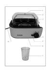
1
• 1 – Introduction • 2 – Troubleshooting • 3 – Removal and Replacement • 4 – Verification Procedures • 5 – Installation Appendix A – Theory of Operation Appendix B – System Description CELL-DYN ® 1200 SYSTEM SERVICE MANUAL Part Number 9140268A – January 2000 1 – Introduction • Table of Contents 1 – Introduction Table of Contents 1.1 Acknowledgments . . . . . . . . . . . . . . . . . . . . . . . . . 1-2 Proprietary Information . . . . . . . . . . . . . . . . . . . . . . . 1-2 Revision Log. . . . . . . . . . . . . . . . . . . . . . . . . . . . . . . 1-2 1.7 Performance Specifications . . . . . . . . . . . . . . . . 1-11 Background Counts. . . . . . . . . . . . . . . . . . . . . . . . 1-11 Precision . . . . . . . . . . . . . . . . . . . . . . . . . . . . . . . . 1-11 1.2 About This Manual . . . . . . . . . . . . . . . . . . . . . . . . . 1-4 Introduction. . . . . . . . . . . . . . . . . . . . . . . . . . . . . . . . 1-4 Service Manual Chapter Descriptions . . . . . . . . . . . 1-4 1.8 References . . . . . . . . . . . . . . . . . . . . . . . . . . . . . . 1-15 1.3 Safety. . . . . . . . . . . . . . . . . . . . . . . . . . . . . . . . . . . . 1-5 Signal Words and Graphic Warning Conventions . . . . . . . . . . . . . . . . . . . . . . . . . . . . . . . 1-5 Biosafety. . . . . . . . . . . . . . . . . . . . . . . . . . . . . . . . . . 1-5 Electrical Safety . . . . . . . . . . . . . . . . . . . . . . . . . . . . 1-6 1.4 Specifications Overview . . . . . . . . . . . . . . . . . . . . 1-7 1.5 Physical Specifications . . . . . . . . . . . . . . . . . . . . . 1-8 Dimensional Specifications. . . . . . . . . . . . . . . . . . . . 1-8 Power Specifications . . . . . . . . . . . . . . . . . . . . . . . . . .1-9 1.6 Environmental Specifications . . . . . . . . . . . . . . . 1-10 Operating Environment Requirements . . . . . . . . . . 1-10 Clearance Requirements . . . . . . . . . . . . . . . . . . . . 1-10 Waste Disposal Requirements . . . . . . . . . . . . . . . . .1-10 CELL-DYN® 1200 SYSTEM SERVICE MANUAL 9140268A – January 2000 1-1 1 – Introduction • 1.1 Acknowledgments 1 – Introduction 1.1 Acknowledgments Proprietary Information This CELL- DYN 1200 System Service Manual was developed for use solely with Abbott Laboratories’ equipment as specified in the operating instructions. The manual is copyrighted by Abbott Laboratories. No part of this document may be reproduced, stored, or transmitted in any form or by any means electronic, mechanical, photocopied, recorded, or otherwise without the prior written permission of Abbott Laboratories. This CELL- DYN 1200 System Service Manual is published by Abbott Diagnostics, a division of Abbott Laboratories, Abbott Park, IL 60064-3500, U. S. A. Please direct all inquiries concerning information in this manual to the foregoing address. This Service Manual was developed for use by trained Abbott Laboratories Field Service Personnel based on Software Version 2.3. The revision status of this manual is the responsibility of the manual holder. In no event shall Abbott Laboratories or its subsidiaries be liable for any damages incurred in connection with or arising from the use of this manual by persons not fully trained by Abbott Laboratories. ©2000 Abbott Laboratories. All rights reserved. Revision Log The Revision Status of this manual is indicated on the following page. Be sure that the guide contains the latest revision of all pages. CELL- DYN® is a registered trademark of Abbott Laboratories. Vacutainer® is a registered trademark of Becton-Dickinson and Company. PharMed™ is a trademark of Norton Performance Plastics. Tygon® is a registered trademark of Norton Performance Plastics. Parker-O-Lube® is a registered trademark of Parker Seal, Inc. Cell-Dyn HemCal™ is a trademark of Abbott Diagnostics, a division of Abbott Laboratories. Sarstedt is a registered trademark of Walter Sarstedt Gerate, Federal Republic of Germany. CELL-DYN® 1200 SYSTEM SERVICE MANUAL 9140268A – January 2000 1-2 1 – Introduction • 1.1 Acknowledgments Table 1-1 Revision Log Revision Date Pages Revised/Added A 01/00 New Manual CELL-DYN® 1200 SYSTEM SERVICE MANUAL TSBs Incorporated 9140268A – January 2000 ISAs Incorporated 1-3 1 – Introduction • 1.2 About This Manual 1.2 About This Manual Chapter 4 – Verification Procedures Introduction This chapter contains procedures to verify the integrity of various instrument functions. These procedures may be used to facilitate troubleshooting, or may be dictated by Troubleshooting and Removal and Replacement. This Service Manual contains the information necessary to troubleshoot, repair, align, and maintain the CELL-DYN 1200 Automated Hematology System. Service Manual Chapter Descriptions The manual contains five chapters. The following describes the contents of each chapter. This chapter also contains procedures such as adjustments, alignments, and calibrations used to ensure proper instrument performance. Chapter 5 – Installation Appendix A – Theory of Operation Chapter 1 – Introduction This section contains an introduction to the system, information on the use of the manual, safety considerations, hematology parameters, and system specifications. Appendix B – System Description Chapter 2 – Troubleshooting This chapter contains procedures to identify and isolate problems. The procedures are presented in a flowchart format and are accompanied by illustrations for added clarity. A detailed explanation of the use of the flowcharts is given at the beginning of the chapter. Chapter 3 – Removal and Replacement This chapter contains procedures to remove and replace subassemblies and components. The procedures are presented in a paragraph format and are accompanied by illustrations for added clarity. CELL-DYN® 1200 SYSTEM SERVICE MANUAL 9140268A – January 2000 1-4 1 – Introduction • 1.3 Safety 1.3 Safety Operation, maintenance, and servicing of hematology systems may expose individuals to potential safety and health hazards. All work must be performed in accordance with procedures described in the Abbott Operator’s and Service Manuals or as directed by an Abbott Hematology Support Representative. Warnings are inserted in this manual to alert personnel to potential hazards. The standard warning conventions including signal words (e.g., Caution) and symbols are described below. Signal Words and Graphic Warning Conventions Signal Words DANGER: Denotes an immediate hazard which, if not avoided, could result in serious injury or death. This signal word represents the highest level of any hazardous situation. WARNING: Denotes a potential hazard which, if not avoided, could result in moderate to serious injury. CAUTION: Denotes a potential hazard that could result in minor injury; also used for conditions or activities that could threaten equipment performance. CELL-DYN® 1200 SYSTEM SERVICE MANUAL Graphic Conventions The general hazard icon identifies an activity or area that may present a hazard to personnel or equipment. The electrical shock icon alerts personnel to the possibility of electrical shock if procedural or engineering controls are not observed. The biohazard icon identifies an activity or area where personnel may be exposed to infectious substances. The electrostatic discharge icon identifies an activity or area where personnel must wear a ground strap while servicing the system. Biosafety WARNING: POTENTIAL BIOHAZARD Consider all clinical specimens, reagent controls, surfaces, or components that contain or have contacted human blood or serum as potentially infectious. Wear gloves, lab coats, and safety glasses, and follow other biosafety practices as specified in the OSHA Bloodborne Pathogen Rule (29CFR Part 1910.1030) or other equivalent biosafety procedures. 9140268A – January 2000 1-5 1 – Introduction • 1.3 Safety WARNING: POTENTIAL BIOHAZARD The aspiration needle/probe are sharp and potentially contaminated with infectious materials. Avoid contact with the tips of the needle/probe. Clean up spills of potentially infectious materials in accordance with established biosafety practices. A generally accepted procedure for cleaning such spills is to absorb the spill with toweling or other absorbent material, wipe the area with a detergent solution, and then wipe the area with an appropriate tuberculocidal disinfectant such as 10% chlorine bleach (1 part 5% filtered bleach with 9 parts deionized water) solution, or 0.5% sodium hypochlorite solution. Electrical Safety WARNING: ELECTRICAL HAZARD When the instrument is powered and protective covers are removed, there are exposed electrical systems that could startle or seriously injure personnel upon contact. Use appropriate safety precautions to prevent body and/or tool contact with live electrical components, especially power supplies. Prior to service or maintenance, the instrument should be decontaminated in accordance with the following: 1. Remove and dispose of contaminated disposables in a regulated medical waste container. 2. Clean and decontaminate the exterior of the instrument using a detergent solution followed by a 10% chlorine bleach (1 part 5% filtered bleach with 9 parts deionized water) solution, 0.5% sodium hypochlorite solution, or other tuberculocidal disinfectant. Flush the fluid pathway as specified in the CELL-DYN 1200 Operator’s Manual. Dispose of waste in accordance with local, state, and federal regulations. Probes, needles, broken glass, slides, and other sharps that are contaminated with potentially infectious substances should be collected in a “sharps” container for disposal as regulated medical waste. Contaminated gloves, wipes, and other disposables should be placed in a standard medical waste container. CELL-DYN® 1200 SYSTEM SERVICE MANUAL 9140268A – January 2000 1-6 1 – Introduction • 1.4 Specifications Overview 1.4 Specifications Overview This section presents the various performance specifications and characteristics of the CELL-DYN 1200 System. In particular, the following are discussed: • Performance Specifications • – Physical Specifications – Power Specifications – Environmental Specifications – Operational Specifications – Performance Specifications Performance Characteristics This section does not describe the limitations of the System. For this information, refer to the CELL-DYN 1200 Operator’s Manual, Section 7: Operational Precautions and Limitations. CELL-DYN® 1200 SYSTEM SERVICE MANUAL 9140268A – January 2000 1-7 1 – Introduction • 1.5 Physical Specifications 1.5 Physical Specifications Dimensional Specifications Dimensional specifications for the CELL-DYN 1200 System are provided in the following tables. Table 1-2 Table 1-3 Physical Dimensions (approximate) Dimension Instrument Height 16.5 Inches (42 cm) Width 16.25 inches (41 cm) Depth 16.25 inches (41 cm) Weight 45 lbs (20 kg) Dimensions after Packaging for Shipment Dimension Instrument Height 29 inches (74 cm) Width 27 inches (67 cm) Depth 27 inches (67 cm) Weight 50 lbs (22.5 kg) CELL-DYN® 1200 SYSTEM SERVICE MANUAL 9140268A – January 2000 1-8 1 – Introduction • 1.5 Physical Specifications Power Specifications The power specifications for the CELL-DYN 1200 System are described in the following table. Refer to the power specifications applicable in your country. Table 1-4 Power Specifications – CELL-DYN 1200 Instrument Input Requirements Range Frequency 90 - 130 VAC 50/60 Hz 200 - 260 VAC 50/60 Hz Table 1-5 Power Specifications – Printer Input Requirements Setting Frequency 120 VAC 50/60 Hz Power Consumption Maximum: ≤ 250 W Standby: ≤ 60 W Run: ≤ 125 W CELL-DYN® 1200 SYSTEM SERVICE MANUAL 9140268A – January 2000 1-9 1 – Introduction • 1.6 Environmental Specifications 1.6 Environmental Specifications Waste Disposal Requirements Environmental specifications include the operating environment required by the CELL-DYN 1200 System, the clearance and waste disposal requirements, and the noise level and heat output that can be expected during normal operation. All waste produced by the CELL-DYN 1200 System must be disposed of according to local, state, and federal regulations. Operating Environment Requirements Temperature: 15 – 30°C (59 – 86°F) Relative Humidity: 20 – 80%, RHNC Clearance Requirements To ensure proper service access and ventilation, provide the CELL-DYN 1200 System with the clearances shown in the following table: Table 1-6 Unit Analyzer Clearance Requirements Above Behind Left Right 10" 6" 6" 6" CELL-DYN® 1200 SYSTEM SERVICE MANUAL 9140268A – January 2000 1 - 10 1 – Introduction • 1.7 Performance Specifications 1.7 Performance Specifications Precision The following performance specifications apply to systems that have been installed and maintained according to the guidelines in the CELL-DYN 1200 System Operator’s Manual and are being operated with the recommended reagents and supplies. Specifications listed apply to all modes and test selections. System performance is expected to meet or exceed the specifications listed. (Typical performance characteristics of systems in routine use are listed in Section 2.9 Performance Characteristics) Fresh whole blood specimens that are used to verify precision specifications should have results that fall within the laboratory’s normal range and should not cause the display of any Suspect Parameter flags for the parameter being studied. The precision values listed in this section are applicable to all modes and test selections. Calculations are based on a total of 20 measurements obtained by pooling blood from a single donor into four tubes, and aspirating each tube a maximum of five times. NOTE: The performance specifications given in this section apply only to reportable parameters. The specifications do not cover parameters provided as quality checks. NOTE: When running replicate precision studies use Open Tube. For procedures for running replicate precision studies, refer to the CELL-DYN 1200 System Operator’s Manual, Section 11: Quality Control. Background Counts Background counts are used to confirm the System’s baseline performance, without a sample. The following table lists acceptable background count limits that must be met. Table 1-7 Background Limits Parameter Background Count Limits WBC ≤ 0.3 K/µL RBC ≤ 0.03 M/µL HGB ≤ 0.2 g/dL PLT ≤ 10 K/µL CELL-DYN® 1200 SYSTEM SERVICE MANUAL 9140268A – January 2000 1 - 11 1 – Introduction • 1.7 Performance Specifications Hemogram Parameters WBC Differential Parameters Precision is a check on routine instrument operation. The table below presents the results of precision specifications for the hemogram parameters. The stated CV% in these tables represents the instrument precision from N=20 replicate runs. Precision specifications for the WBC differential parameters are given as a range of values for each of the WBC subpopulations. Table 1-8 Within Sample Precision of the Hemogram Parameters Table 1-9 Precision of the WBC Differential Parameters Parameter Range CV% LYMPH% 15 – 64% ± 3.1% Parameter Range USA CV% MID% 4 – 9% ± 1.6% WBC 2.8 – 12.5 K/µL ≤ 4.0% GRAN% 30 – 78% ± 3.5% RBC 3.05 – 6.36 M/µL ≤ 2.0% HGB 9.9 – 18.9 g/dL ≤ 1.2% MCV 80.1 – 103.8 fL ≤ 1.5% RDW 10.4 – 16.7% ≤ 2.7% PLT 112 – 440 K/µL ≤ 5.0% MPV 7.6 – 13.7 fL ≤ 6.0% CELL-DYN® 1200 SYSTEM SERVICE MANUAL 9140268A – January 2000 1 - 12 1 – Introduction • 1.7 Performance Specifications Linearity Linearity specifications are determined by analyzing dilutions of a sample or commercially available control material that contains no interfering substances and displays no suspect parameter flags. Specifications are determined by taking multiple measurements on each dilution to minimize the effect Table 1-10 of imprecision. The stated limits in the table below are determined by linear regression through the origin (0,0), assuring that the collected data throughout the linear reportable range does not exceed the stated Allowable Limits in the table. Linearity Specifications Parameter Linear Reportable Range Absolute Deviation* Relative Deviation* WBC 0.4 - 91.8 x K/µL ± 0.4 ± 3.0% RBC 0.21 - 7.77 x M/µL ± 0.1 ± 2.5% HGB 0.7 - 23.0 g/dL ± 0.3 ± 2.0% MCV 50.0 - 200 fL ± 3.0 ± 3.0% PLT 7 - 970 x K/µL ± 12.0 ± 4.0% MPV 5.0 - 18.0 fL ± 1.0 ± 6.0% * Whichever is greater. Applies to actual mean value obtained in reference to the expected value. CELL-DYN® 1200 SYSTEM SERVICE MANUAL 9140268A – January 2000 1 - 13 1 – Introduction • 1.7 Performance Specifications Correlation Carryover Evaluation of the correlation of the CELL-DYN 1200 is demonstrated in the table below. This data was computed from regression analysis of data obtained from studies performed on whole blood samples (a minimum of 150 normal and 150 abnormal) analyzed against a reference instrument using similar technology. None of the samples used for the correlation studies exhibited any suspect parameter (RO or RM) flags. The table below shows carryover percent and absolute for WBC, RBC, HGB, and PLT. Carryover is determined by running samples with high concentrations of WBCs, RBCs, HGB, and PLTs. Each sample is run in triplicate followed by three background cycles. Carryover is calculated using the following formula: Table 1-11 Background 1 – Background 3 Carryover = --------------------------------------------------------------------------------- × 100 Sample 3 – Background 3 Whole Blood Accuracy Results Range Correlation Coefficient WBC 0.1 - 95.0 K/µL ≥ 0.98 LYMPH % 2.9 - 91.6% ≥ 0.92 MID % 1.3 - 29.4% ≥ 0.60 Parameter Level Carryover* GRAN % 6.9 - 90.8% ≥ 0.92 WBC 82.8 K/µL ≤ 1.0% or 0.1 K/µL RBC 0.40 - 7.31 M/µL ≥ 0.98 RBC 7.54 M/µL ≤ 0.5% or 0.03 M/µL HGB 1.3 - 22.4 g/dL ≥ 0.98 HGB 23.3 g/dL ≤ 0.8% or 0.1 g/dL HCT 16.4 - 53.5% ≥ 0.95 PLT 982 K/µL ≤ 1.0% or 10 K/µL MCV 48.2 - 124.0 fL ≥ 0.95 RDW 10.2 - 28.2% ≥ 0.92 PLT 4 - 934 K/µL ≥ 0.98 MPV 5.9 - 14.3 fL ≥ 0.80 Parameter CELL-DYN® 1200 SYSTEM SERVICE MANUAL Table 1-12 Carryover *Whichever is greater 9140268A – January 2000 1 - 14 1 – Introduction • 1.8 References 1.8 References 1. National Committee for Clinical Laboratory Standards. Method Comparison and Bias Estimation Using Patient Samples. Approved Guideline. NCCLS Document EP9-A. Wayne, PA. 1995. 2. National Committee for Clinical Laboratory Standards. Reference Leukocyte Differential Count (Proportional) and Evaluation of Instrumental Methods. Approved Guideline. NCCLS Document H20-A. Wayne, PA. 1992. CELL-DYN® 1200 SYSTEM SERVICE MANUAL 9140268A – January 2000 1 - 15 2 – Troubleshooting • Table of Contents 2 – Troubleshooting Table of Contents 2.1 2.2 IP-1 IP-2 IP-3 IP-4 IP-5 IP-6 IP-7 IP-8 IP-9 IP-10 IP-11 IP-12 How to Use This Chapter . . . . . . . . . . . . . . . . . . . . .2-2 To Troubleshoot a Problem: . . . . . . . . . . . . . . . . . 2-2 Error Messages . . . . . . . . . . . . . . . . . . . . . . . . . . . . .2-3 Backgrounds Too High . . . . . . . . . . . . . . . . . . . . . . .2-4 Impedance Imprecision . . . . . . . . . . . . . . . . . . . . . .2-5 HGB Precision . . . . . . . . . . . . . . . . . . . . . . . . . . . . .2-8 Histogram Problems . . . . . . . . . . . . . . . . . . . . . . . . .2-9 Controls Out . . . . . . . . . . . . . . . . . . . . . . . . . . . . . .2-10 Reagent Empty. . . . . . . . . . . . . . . . . . . . . . . . . . . .2-12 External Waste Full . . . . . . . . . . . . . . . . . . . . . . . .2-15 Print Errors . . . . . . . . . . . . . . . . . . . . . . . . . . . . . . .2-17 Blank Display . . . . . . . . . . . . . . . . . . . . . . . . . . . . .2-19 Non-Functional/Dead Instrument . . . . . . . . . . . . . .2-20 RBC/PLT/WBC/HGB Problems . . . . . . . . . . . . . . .2-24 MCV, MPV Problems . . . . . . . . . . . . . . . . . . . . . . .2-29 Appendix 2A – Cable Interconnect & Main Board Connector Pin-Outs. . . . . . . . . . . . . . . . .2A-1 Figure 2A-1 Cable Interconnect Diagram . . . . . . . . . . .2A-1 Figure 2A-2 Main Board Connector Pin-outs . . . . . . . .2A-2 CELL-DYN® 1200 SYSTEM SERVICE MANUAL Appendix 2B – System Block Diagrams . . . . . . . . . . . . Figure 2B-1 Data Interface Subsystem . . . . . . . . . . . . Figure 2B-2 Measurement Subsystem. . . . . . . . . . . . . Figure 2B-3 D/A Subsystem. . . . . . . . . . . . . . . . . . . . . Figure 2B-4 A/D Subsystem. . . . . . . . . . . . . . . . . . . . . Figure 2B-5 Fluid Sensor Interface . . . . . . . . . . . . . . . Figure 2B-6 Sensor Subsystem . . . . . . . . . . . . . . . . . . Figure 2B-7 Motor Subsystem . . . . . . . . . . . . . . . . . . . Figure 2B-8 Solenoid Subsystem. . . . . . . . . . . . . . . . . Figure 2B-9 Power Distribution Subsystem . . . . . . . . . 2B-1 2B-1 2B-2 2B-3 2B-4 2B-5 2B-6 2B-7 2B-8 2B-9 Appendix 2C – System Flow Diagrams . . . . . . . . . . . . . 2C-1 Figure 2C-1 Flow Diagram . . . . . . . . . . . . . . . . . . . . . . 2C-1 Figure 2C-2 Vacuum & Pressure Flow Diagram . . . . . 2C-2 Figure 2C-3 Reagents Flow Diagram. . . . . . . . . . . . . . 2C-3 Figure 2C-4 Dilution & Mixing Flow Diagram . . . . . . . . 2C-4 Figure 2C-5 Sample Staging Flow Diagram. . . . . . . . . 2C-5 Figure 2C-6 Sample Delivery Flow Diagram . . . . . . . . 2C-6 Figure 2C-7 Cleaning & Waste Flow Diagram . . . . . . . 2C-7 9140268A – January 2000 2-1 2 – Troubleshooting • 2.1 How to Use This Chapter 2 – Troubleshooting 2.1 How to Use This Chapter This chapter is designed to aid the FSR in troubleshooting and repairing the CELL-DYN 1200 System. Emphasis is placed on using various System Status and Fault Reports, which can be accessed by the FSR, to solve problems. Special Service Commands are also available to exercise and observe mechanical and electronic functions. This chapter contains: • Error list which provides Error/Corrective Action information for errors and observed problems • Isolation Procedure (IP) Flowcharts for most common System failures • System Interconnect Diagram • System Fluidic Diagram To Troubleshoot a Problem: 1. Find the SIM, AIM, or observed problem in the Error Messages table on the following page. 2. Click on Corrective Action IP for that error. 3. Follow the Isolation Procedure Flowchart until problem is resolved. 4. See Section 4.2 Verification Matrix and perform the VPs in order listed, to restore the System to full operation. All Verification Procedures (VPs) and Removal/Replacement (RRs) Procedures in the flowcharts are linked for easy access. CELL-DYN® 1200 SYSTEM SERVICE MANUAL 9140268A – January 2000 2-2 2 – Troubleshooting • 2.2 Error Messages 2.2 Error Messages Table 2-1 Error Messages Error Corrective Action Background, HGB Too High (IP-1) Background, RBC/ PLT Too High (IP-1) Background, WBC Too High (IP-1) Controls Out (IP-5) Diluent/Sheath Empty (IP-6) Erratic Results, HGB (IP-11) Erratic Results, Impedance (IP-11) External Waste Full (IP-7) HCT Errors (IP-11), (IP-12) HGB Errors (IP-11), (IP-3) Histogram Errors (IP-4) MCH Errors (IP-11), (IP-3) MCHC Errors (IP-11), (IP-3), (IP-12) MCV Errors (IP-12) Precision Problems HGB (IP-3), Imp. (IP-2) Printer Errors (IP-8) WBC Imprecision (IP-2) WBC/HGB Lyse Empty (IP-6) CELL-DYN® 1200 SYSTEM SERVICE MANUAL 9140268A – January 2000 2-3 2 – Troubleshooting • IP-1 Backgrounds Too High IP-1 Backgrounds Too High (1 of 1) Start - Verify Background Counts (VP-6) NO - Verify instrument environment per Pre-installation Check List - Perform the following in order and verify backgrounds after each action taken. - From Main Menu, press - Ensure Ground connectors around Impedance Transducer are clean and making good contact. ! UTILITY ! DIAGNOSTICS - Perform Autoclean. (VP-6) ! SYSTEM TESTS WBC Only Too High ? YES - Clean Vacuum/Pressure Pump. (VP-29) - Clean Aperture Plate. (VP-4) ! MORE To ! SET POINTS - Verify RBC Threshold is 240 and PLT Threshold is 230. - Replace Diluent Container. NO - Replace Diluent and Sample Injection Syringes. - Ensure RBC/PLT Mixing Chamber is being rinsed and drained properly. - INITIALIZE and PRIME Instrument. - Replace +24V Power Supply. - Run multiple backgrounds and verify. - Replace Auxiliary Power Supply Board. - From Main Menu, press ! UTILITY ! DIAGNOSTICS ! SYSTEM TESTS ! MORE To ! SET POINT ENTRY - Verify WBC Threshold is 240. - Replace Lyse Container. - Replace HGB Syringe. Backgrounds OK ? YES Total Call - INITIALIZE and PRIME Instrument. CELL-DYN® 1200 SYSTEM SERVICE MANUAL 9140268A – January 2000 2-4 2 – Troubleshooting • IP-2 Impedance Imprecision IP-2 Impedance Imprecision (1 of 3) Note: This procedure assumes there are no gross problems with values. It is designed to find problems where the RBC/PLT/WBC precision is slightly out-of-range. For gross problems refer to IP-11. Start - Verify reagents, type and expiration date. - Clean Fan Filter and verify Fan is running properly. - Ensure there is at least 6" of clearance behind Instrument. - Ensure Instrument is not subject to drastic temperature variations (direct sunlight, heating/air conditioning ducts). - If Fan Filter was clogged and then cleaned, allow a 15 minute temperature stabilization period. Problem Corrected All Imprecise ? ? YES NO YES - Verify Background Counts. (VP-5). RBC/PLT Only YES 3 ? NO 1 - Perform Autoclean. (VP-6) - Verify System Precision. (VP-8) 2 NO Total Call - Clean Aperture Plate. (VP-4) - Clean V/P Pump. (VP-29) YES Backgrounds OK ? NO CELL-DYN® 1200 SYSTEM SERVICE MANUAL Go to (IP-1). 9140268A – January 2000 2-5 2 – Troubleshooting • IP-2 Impedance Imprecision IP-2 Impedance Imprecision (2 of 3) 1 - Replace Lyse Container 2 - Clean HGB Flow Cell. YES WBC Only ? NO - Flush Lyse Inlet line out to waste. - Clean V/P Pump. (VP-29) - Clean V/P Pump. (VP-29) - Check opening of Solenoid 2-3. - Verify Solenoid 3-1 operation. - From Main Menu, press - Ensure Pre-Mix Cup and HGB Flow Cell are being rinsed and drained properly. ! DIAGNOSTICS ! SYSTEM TESTS - Ensure Pre-Mix Cup and HGB Flow Cell are being bubble mixed properly. ! MORE To ! SET POINTS - Verify WBC Threshold is 240. Total Call - Ensure Pre-Mix Cup and HGB Flow Cell are being rinsed and drained properly. - Ensure Pre-Mix Cup and HGB Flow Cell are being bubble mixed properly. - Verify operation of Lyse Syringe. (VP-17) Troubleshoot as necessary. - Verify/adjust WBC Gain. (VP-11) - Replace Main Board. - Verify operation of Vacuum/ Pressure Pump. (VP-17), (VP-20), (VP-19) - Verify sheath flow through Valve 28. Troubleshoot as necessary. - Verify proper diluent flow through Wash Block, operation of Valves 26 and 12 (VP-17), and associated tubing. Replace as necessary. - Verify operation of Sample Injection Syringe. (VP-17) Troubleshoot as necessary. - Replace Aperture Plate. - Replace Impedance Transducer. - Replace Main Board. CELL-DYN® 1200 SYSTEM SERVICE MANUAL 9140268A – January 2000 2-6 2 – Troubleshooting • IP-2 Impedance Imprecision IP-2 Impedance Imprecision (3 of 3) 3 - Replace Diluent Container. - Verify Solenoid 2-4 operation. - Clean Vacuum/Pressure Pump. (VP-29) - From Main Menu, press ! DIAGNOSTICS ! SYSTEM TESTS ! MORE To ! SET POINTS - Verify RBC Threshold is 240. - Verify PLT Threshold is 230. - Ensure RBC Mix Cup is being rinsed, drained, and bubble mixed properly. - Verify operation of Diluent Syringe. (VP-17) Troubleshoot as necessary. - Verify/adjust RBC Gain. (VP-9) - Verify/adjust PLT Gain. (VP-10) - Replace Main Board. CELL-DYN® 1200 SYSTEM SERVICE MANUAL 9140268A – January 2000 2-7 2 – Troubleshooting • IP-3 HGB Precision IP-3 HGB Precision (1 of 1) Note: This procedure assumes there are no gross problems with the HGB value. It is designed to find problems where the HGB precision is slightly out-of-range. For gross problems refer to IP-11. Start - Clean Fan Filter and verify Fan is running properly. - Ensure there is at least 6" of clearance behind Instrument. - Ensure Instrument is not subject to drastic temperature variations (direct sunlight, heating/air conditioning ducts). - If Fan Filter was clogged and then cleaned, allow a 15 minute temperature stabilization period. - Clean HGB Flow Cell. (VP-7) - Ensure HGB Flow Cell tubing is not restricted. HGB CVs OK - Ensure HGB Flow Cell is being rinsed and drained properly. ? YES - Ensure HGB Flow Cell is being bubble mixed properly. NO Total Call NO - Replace HGB Lyse Container. - Verify operation of Lyse Syringe. (VP-17) - Clean Vacuum/Pressure Pump. (VP-29) - Replace Lyse Syringe. - Replace HGB Flow Cell. - Verify System Precision. (VP-8) - Replace Main Board. HGB CVs OK ? YES Total Call CELL-DYN® 1200 SYSTEM SERVICE MANUAL 9140268A – January 2000 2-8 2 – Troubleshooting • IP-4 Histogram Problems IP-4 Histogram Problems (1 of 1) Start - Perform the following in order and verify histograms after each action taken. - Verify reagents; type and expiration date. - Ensure RBC/PLT and/or HGB Flow Cell are being rinsed and drained properly. - Ensure reagents are at room temperature. - Verify Backgrounds. (VP-5) NO Go to (IP-1) - Clean Impedance Aperture. NO (VP-4) ? - Clean Vacuum/Pressure Pump. (VP-29) YES - Replace Diluent, Lyse, and Sample Injection Syringes. - Replace Lyse for WBC problem or Diluent for RBC/ PLT problem. WBC Only ? - Ensure RBC/PLT and/or HGB Flow Cell are being bubble mixed properly. - Perform Autoclean. (VP-6) Backgrounds OK Parameters Affected RBC/PLT NO - Verify operation of and tubing in Valve 22. Replace as necessary. (VP-21) - Verify PLT Gain. (VP-10) - Verify WBC Gain. (VP-11) - Replace Impedance Preamplifier. - Replace Impedance Preamplifier. - Replace Main Board. - Replace Main Board. - Verify RBC Gain. (VP-9) Problem Corrected Problem Corrected ? YES ? YES Total Call Total Call CELL-DYN® 1200 SYSTEM SERVICE MANUAL 9140268A – January 2000 2-9 2 – Troubleshooting • IP-5 Controls Out IP-5 Controls Out (1 of 2) Start - Verify reagents; type and expiration date. - Open fresh Controls and run QC. (VP-26) - Ensure reagents are at room temperature and have not been previously frozen. - Ensure Controls and Calibrators have not been frozen or heat stressed. - Check Control Lot #. YES - Use current Control Insert Sheet to verify means/limits are correct if customer has not established their own means. NO - Verify System Precision. (VP-8) Precision In Spec Controls OK ? ? - Perform Autoclean. (VP-6) - Verify Backgrounds. (VP-5) NO YES - Clean Vacuum/Pressure Pump. (VP-29) Total Call - Go to (IP-2) for Impedance and/or (IP-3) for HGB. Correct and return here. YES Backgrounds OK 1 ? NO Go to (IP-1). Correct and return here. CELL-DYN® 1200 SYSTEM SERVICE MANUAL 9140268A – January 2000 2 - 10 2 – Troubleshooting • IP-5 Controls Out IP-5 Controls Out (2 of 2) 1 YES - Run QC Controls. (VP-26) Parameter(s) >10% Out ? NO - Recalibrate out-of-range parameter(s). (VP-13) - Determine which parameter(s) are out-ofrange, and go to (IP-11) for RBC, PLT, WBC, and HGB problems and (IP-12) for MCV problems. - For indices (MCH or MCHC), determine which parameter (HGB, MCV, or RBC is imprecise and troubleshoot accordingly. MCH = HGB X10 RBC MCHC = HGB X 1000 MCV X RBC - Run QC Controls. (VP-26) CELL-DYN® 1200 SYSTEM SERVICE MANUAL 9140268A – January 2000 2 - 11 2 – Troubleshooting • IP-6 Reagent Empty IP-6 Reagent Empty (1 of 3) Start - Verify reagents, type and expiration. - Ensure reagent containers are connected to the correct tubing and input ports. - Ensure sinker is on Diluent line and lines are at bottom of containers. - Ensure reagent lines are not crimped or clogged. - INITIALIZE and PRIME instrument. YES Lyse Empty ? NO YES - Open Left Front Door and observe Lyse Syringe. - Open Left Front Door and observe Diluent Syringe. From Main Menu, press ! RUN From Main Menu, press ! CLEAR ALARM ! RUN ! CLEAR ALARM Diluent Empty ? NO Total Call Syringe Moving OK ? YES 2 Syringe Moving OK ? YES 1 NO NO - Replace syringe. - Verify Syringe Driver operation. (VP-17) - Replace Syringe Driver Assembly. - Replace Main Board. CELL-DYN® 1200 SYSTEM SERVICE MANUAL 9140268A – January 2000 - Replace syringe. - Verify Syringe Driver operation. (VP-17) - Replace Syringe Driver Assembly. (RR-4) - Replace Main Board. 2 - 12 2 – Troubleshooting • IP-6 Reagent Empty IP-6 Reagent Empty (2 of 3) 1 YES Syr/Lines Filling OK ? NO - Using clip leads, short clips on Lyse Sensor. See Figure on this page. - Remove and clean clips and sensor connections. NO From Main Menu, press ! RUN ! CLEAR ALARM Sensor - Verify Lyse Syringe is not leaking. Replace as necessary. - Verify operation and tubing in valves 16 and 22. (VP-21) Replace as necessary . - Apply air pressure with a 10cc luer lock syringe to top port of Lyse syringe to remove possible Lyse plug back to bottle. - Apply air pressure with 10cc luer lock syringe to bottom port to remove Lyse plug back to HGB Flow Cell. - Replace sensor. Lyse Empty ? Short Clips Not Sensor 12055 YES - Check cable from clip leads to Main Board and connector at J47. Replace as necessary. - Replace Main Board. CELL-DYN® 1200 SYSTEM SERVICE MANUAL 9140268A – January 2000 2 - 13 2 – Troubleshooting • IP-6 Reagent Empty IP-6 Reagent Empty (3 of 3) 2 YES Syr/Lines Filling OK ? - Using clip leads, short clips on Diluent Sensor. See the Figure on Page 2 of this procedure. From Main Menu, press - Remove and clean clips and sensor connections. - Replace sensor. NO ! RUN ! CLEAR ALARM NO - Verify Injection and Diluent Syringes are not leaking. Replace as necessary. - Verify operation of Check Valve. Replace as necessary. - Verify operation and tubing in valves 13, 14, 27, 26. (VP-21) Replace as necessary. - Verify operation of Vacuum/ Pressure Pump. (VP-17) Replace as necessary. CELL-DYN® 1200 SYSTEM SERVICE MANUAL Diluent Empty ? YES - Check cable from clip leads to Main Board and connector at J47. Replace as necessary. - Replace Main Board. 9140268A – January 2000 2 - 14 2 – Troubleshooting • IP-7 External Waste Full IP-7 External Waste Full (1 of 2) Start Sensor Cable Used ? NO - Ensure Dummy Plug is installed - Reseat Dummy Plug 12053 YES - Empty Waste Container Problem Corrected - Reseat Waste Sensor Plug - INITIALIZE and PRIME instrument. YES Total Call ? NO Problem Corrected NO ? YES CELL-DYN® 1200 SYSTEM SERVICE MANUAL - Insert Insulated Tool into Sensor Jack to open contacts. See Figure. 1 Total Call 9140268A – January 2000 2 - 15 2 – Troubleshooting • IP-7 External Waste Full IP-7 External Waste Full (2 of 2) 1 Problem Corrected YES ? - Disconnect Sensor Cable from Waste Container and Sensor Jack and verify infinite resistance between Fluid Contacts. Replace as necessary. Problem Corrected NO YES Total Call ? NO Perform in the following order until problem is corrected: - Check and reseat J47 on Main Board. Replace as necessary. - Replace Waste Sensor Jack. - Replace Main board. CELL-DYN® 1200 SYSTEM SERVICE MANUAL 9140268A – January 2000 2 - 16 2 – Troubleshooting • IP-8 Print Errors IP-8 Print Errors (1 of 2) Start - Ensure printer cable is connected properly. - Cycle printer and instrument power. - Ensure paper is loaded properly. - Press On-line Button. - Initialize and prime instrument. - Check power and power cable. NO Printer On-Line - Try printing with alternate Printer Cable. ? YES Printer On-Line ? Prints OK NO NO - Replace Printer. - Perform printer test. (VP-15) NO ? 1 YES - Replace Printer Cable. YES Total Call Printer OK ? YES Total Call CELL-DYN® 1200 SYSTEM SERVICE MANUAL 9140268A – January 2000 2 - 17 2 – Troubleshooting • IP-8 Print Errors IP-8 Print Errors (2 of 2) 1 - Connect Laptop to receive data output. - Replace Main Board. NO Is Output Received ? YES - Replace Printer. CELL-DYN® 1200 SYSTEM SERVICE MANUAL 9140268A – January 2000 2 - 18 2 – Troubleshooting • IP-9 Blank Display IP-9 Blank Display (1 of 1) Start - Close Safety Door, Cycle Analyzer Power, and verify the following: - Press any key. - Check cables at J1, J2, and J5 on LCD Interface Board. Replace as necessary. Stepper Motors all home. Valves activate. Problem Corrected ? NO Ready LED illuminates after prime. - Press "+" Brightness Control up to 25 times. See Figure. - Replace LCD Interface Board. - Replace Liquid Crystal Display. - Replace Main Board. YES Total Call YES Init/Prime OK YES Problem Corrected ? Display + NO ? NO - Troubleshoot "dead" Analyzer problem. (IP-10) 12058 CELL-DYN® 1200 SYSTEM SERVICE MANUAL 9140268A – January 2000 2 - 19 2 – Troubleshooting • IP-10 Non-Functional/Dead Instrument IP-10 Non-Functional/Dead Instrument (1 of 4) Start CAUTION: Do not connect or disconnect any connector with the System Power on. - Check Power Source, Cord, Input Filter, and Power Switch. Replace as necessary. 6 J2 PFD 5 +24V RET +24V RTN 1 2 3 4 - Perform System Voltage Verification. (VP-16) +24V 5 6 7 8 4 +24V RET 3 KEY 2 +24V 1 +24V +24V Power Supply +24VDC OK ? 12 11 10 9 -12V GND 8 +5V 7 +5V 6 +12V 5 KEY 4 Aux. Power Supply J1 PFD +24V RET NO GND 3 +24V RET 2 +24V 1 +24V YES 12061 Main Board +12V KEY +24V RET +24V RET +24V +24V +5V +5V GND GND -12V PFD 12 11 10 9 - Remove J1 from Main Board and check voltage at cable pins again. 8 7 6 CELL-DYN® 1200 SYSTEM SERVICE MANUAL 5 4 3 2 1 2 +24VDC OK ? NO YES 1 - One at a time, disconnect Main board connectors at J49, J101, J102, J103, J104, J105, and J106, and re-check +24V after each to find component loading down +24V. Replace loading component as necessary. - If no loading component is found, replace Main Board. Note: Refer to the Cable Interconnect Diagram to determine loading component. J1 9140268A – January 2000 2 - 20 2 – Troubleshooting • IP-10 Non-Functional/Dead Instrument IP-10 Non-Functional/Dead Instrument (2 of 4) 1 - Check +24V at TB2 on +24V Power Supply. - Refer to the Figure on Page 1 of this procedure and check +24V at J1 on Auxiliary Power Supply. +24VDC OK ? YES NO +24VDC OK ? - One at a time, disconnect Auxiliary Power Supply connectors at first J6, NO second J7, and third J2 and re-check +24V at TB2 after each to find component loading down +24V. Replace loading component as necessary. - If no loading component is found, replace +24V Power Supply. YES - Replace cable from J1 on Auxiliary Power Supply to TB2 on +24V Power Supply. Note: Refer to the Cable Interconnect Diagram to determine loading component. - Replace cable from J1 on Auxiliary to J1 on Main Board. CELL-DYN® 1200 SYSTEM SERVICE MANUAL 9140268A – January 2000 2 - 21 2 – Troubleshooting • IP-10 Non-Functional/Dead Instrument IP-10 Non-Functional/Dead Instrument (3 of 4) 2 +5V OK ? YES NO 3 - Refer to the Figure on Page 1 of this procedure and check +5V at J1 on Auxiliary Power Supply. - One at a time, disconnect Main board connectors at J6, J7, J39, J49, J51,J52, J53, J54, and J55 and re-check +5V after each to find component loading down +5V. Replace loading component as necessary. YES +5V OK ? - If no loading component is found, replace Main Board. - Remove J1 from Main Board and check voltage at cable pins again. CELL-DYN® 1200 SYSTEM SERVICE MANUAL - Replace cable from J1 on Auxiliary Power Supply to J1 on Main Board. NO Note: Refer to Cable Interconnect Diagram to determine loading component. +5V OK ? YES - Replace Auxiliary Power Supply. NO 9140268A – January 2000 2 - 22 2 – Troubleshooting • IP-10 Non-Functional/Dead Instrument IP-10 Non-Functional/Dead Instrument (4 of 4) YES - Load System Software. (VP-2) 3 - Replace Main Board. ±12V OK ? NO - Remove J1 from Main Board and check voltage at cable pins again. YES ±12V OK ? CELL-DYN® 1200 SYSTEM SERVICE MANUAL - Refer to the Figure on Page 1 of this procedure and check ±12V at J1 on Auxiliary Power Supply. - Disconnect Main board connector at J20 and recheck ±12V to see if Impedance Preamplifier is loading down ±12V. Replace if loading. ±12V OK ? - If not loading, replace Main Board. YES - Replace cable from J1 on Auxiliary Power Supply to J1 on Main Board. NO NO - Replace Auxiliary Power Supply. 9140268A – January 2000 2 - 23 2 – Troubleshooting • IP-11 RBC/PLT/WBC/HGB Problems IP-11 RBC/PLT/WBC/HGB Problems (1 of 5) Note: This procedure assumes that the display, motors, and solenoids appear to be operating properly, and there are no hardware or software Error Messages. It is designed to find and correct gross RBC, PLT, WBC, and HGB problems. For Precision Problems see IP-2 and IP-3. Start All L/H/E - Verify proper Reagents and Expiration Date. All "0" RBC and/or PLT Only "0"/L/H/E 2 ? - Run a Normal Control five times and record the values. - Observe the RBC, PLT, WBC, and HGB values, and determine which are "0", low, high, or erratic. YES YES 5 ? NO NO NO RBC, PLT, & WBC Only "0" ? YES WBC and HGB Only L/H/E ? 3 YES 6 YES 8 NO NO NO ? YES 1 RBC, PLT, & WBC Only L/H/E ? YES 4 ? NO Note: "0" = Zero or Approximately Zero, L = Low, H = High, E = Erratic, / = Or CELL-DYN® 1200 SYSTEM SERVICE MANUAL WBC Only "0"/L/H/E 9140268A – January 2000 7 2 - 24 2 – Troubleshooting • IP-11 RBC/PLT/WBC/HGB Problems IP-11 RBC/PLT/WBC/HGB Problems (2 of 5) 7 2 1 - Replace Main Board. HGB Only "0"/L/H/E YES - Verify +12V and -12V. (VP-16) YES ? - Clean Aspiration Probe. (VP-22) - Replace Aspiration Probe. 9 - Verify Diluent and Sample Syringe operation, and Vacuum/Pressure Pump operation. (VP-17) Replace as necessary. NO Total Call Voltages OK ? - Verify operation of Valve 38. (VP-21) NO - Verify bubble mixing through Valve 38. - Replace Main Board. - Check cable Main Board J1 to Auxiliary Power Supply J1. Replace as necessary. - Replace Auxiliary Power Supply. CELL-DYN® 1200 SYSTEM SERVICE MANUAL 9140268A – January 2000 2 - 25 2 – Troubleshooting • IP-11 RBC/PLT/WBC/HGB Problems IP-11 RBC/PLT/WBC/HGB Problems (3 of 5) 3 - Check cable Main Board J20 to Impedance Preamplifier J3. Replace as necessary. NO - Perform Test Pulse Verification. (VP-24) - Replace Impedance Preamplifier. - Replace Main Board. Test Passed ? - Check cable Auxiliary Power Supply J4 to Impedance Preamplifier J2. Replace as necessary. - Check connections on Impedance Transducer. - Verify opeation of and tubing in Valves 25 and 34. (VP-21) Replace as necessary. YES - Clean/replace Sample Injection Syringe. YES - Perform Sample Injection Verification. (VP-25) YES - Replace Auxiliary Power Supply. NO - Open Rear Door and check +100V (93V 107V) at J4 of Auxiliary Power Supply. Sample Injection OK ? NO Voltage OK ? CELL-DYN® 1200 SYSTEM SERVICE MANUAL - Manually clean Aperture Plate. (VP-4) - Check Injection Nozzle and plumbing for restrictions. - Replace Impedance Transducer Assembly. 9140268A – January 2000 2 - 26 2 – Troubleshooting • IP-11 RBC/PLT/WBC/HGB Problems IP-11 RBC/PLT/WBC/HGB Problems (4 of 5) 4 5 YES - Verify Background Counts. (VP-5) YES - Manually clean Aperture Plate. (VP-4) - Verify Background Counts. (VP-5) - From Main Menu, press ! UTILITY ! DIAGNOSTICS - Replace Sample Injection Syringe. - Verify operation of Vacuum/Pressure Pump. (VP-17) Backgrounds OK - Verify pressure. (VP-20) ? - Verify sheath flow and operation of Valve 28. (VP-21) NO Go to (IP-1), correct and return here. NO - Verify operation of and tubing in Valves 13, 32, 33, 34, 36, and 37. (VP-21) ! SYSTEM TESTS ! MORE To NO - Verify RBC/PLT gains. (VP-9), (VP-10) Go to (IP-1), correct and return here. - Replace Impedance Transducer. - Replace Main Board. ? Problem Corrected ? YES Total Call CELL-DYN® 1200 SYSTEM SERVICE MANUAL - Verify RBC Threshold is 240, PLT Lo Threshold is 230, and PLT HI Threshold is 4095. ? - Replace Aperture Plate. Problem Corrected ! SET POINT ENTRY Backgrounds OK YES Total Call 9140268A – January 2000 NO - Replace Diluent Container. - Check RBC Mix Cup outlet plumbing for debris and restrictions. - Verify operation of and tubing in Valve 21. (VP-21) - Verify RBC Mix Cup is being bubble mixed properly. - Replace Main Board. 2 - 27 2 – Troubleshooting • IP-11 RBC/PLT/WBC/HGB Problems IP-11 RBC/PLT/WBC/HGB Problems (5 of 5) 6 9 - Replace Lyse Container. - Replace Lyse Container. - Replace Lyse Syringe. - Clean HGB Flow Cell. (VP-7) - Check Pre-Mix Cup and HGB Flow Cell outlet plumbing for debris and restrictions. - Verify operation of and tubing in Valve 22. (VP21) 8 12 10 From Main Menu, press Total Call - Verify HGB Flow Cell is being rinsed and drained properly. 11 - Verify there are no large bubbles remaining in HGB Flow Cell. ! UTILITY ! DIAGNOSTICS - Replace HGB Flow Cell. ! DATA REVIEW - Perform HGB Current Adjustment. (VP-12) - Run five Background Counts and record the HGB Ref and HGB Sample values. - Replace Lyse Container. - Verify WBC threshold Setpoint is 240. - Replace Main Board. 13 Select path from values below. Reference Sample - Verify WBC gain (VP-11) 1850-2250 1850-2250 10 - Verify operation of and tubing in Valve 23. (VP-21) - Check cable from HGB Flow Cell to Main Board J48. < 1850 < 1850 11 - Replace HGB Flow Cell. - Replace Main Board. > 2250 >2250 11 CELL-DYN® 1200 SYSTEM SERVICE MANUAL Erratic Erratic 12 "0" "0" 13 9140268A – January 2000 - Replace Main Board. 2 - 28 2 – Troubleshooting • IP-12 MCV, MPV Problems IP-12 MCV, MPV Problems (1 of 1) Start MPV ONLY MCV ONLY - Replace Diluent Container. - Verify RBC gain. (VP-9) Parameter(s) Affected ? - Replace Diluent Container. - Verify PLT gain. (VP-10) - Replace Main Board. - Replace Main Board. BOTH - Replace Diluent Container. - Manually clean Aperture Plate. (VP-4) - Verify RBC and PLT gains. (VP-9), (VP-10) - Check for leaks around Aperture Plate. - Replace Aperture Plate. - Replace Impedance Transducer Assembly. - Replace Impedance Preamplifier. - Replace Main Board. CELL-DYN® 1200 SYSTEM SERVICE MANUAL 9140268A – January 2000 2 - 29 Appendix 2A – Cable Interconnect & Main Board Connector Pin-Outs Appendix 2A –Cable Interconnect & Main Board Connector Pin-Outs Figure 2A-1 Cable Interconnect Diagram Transducer Fluid Sensors Preamp J3 PCB 9602210 9210444 Status PCB 9602300 Waste 9521055 Lyse HGB Assy Diluent Assy 9210443 9521038 J1 9210438 J47 J48 J20 J39 Up/Down Mtr (MTR_B) 9521057 Up/Down Snsr (SENSOR_B) J52 Left/Right Mtr (MTR_C) J53 Left/Right Snsr (SENSOR_C) J49 J51 Main PCB 960197 0 COM 1 J3 Printer (LPT-1) Pneumatic Mtr (MTR_A) J102 Pneumatic Snsr (SENSOR_A) J103 J104 J2 Pin 1-1 1-2 J105 J5 J7 J106 J6 2-1 9521056 Floppy Disk Drive 2005702 9521052 Data LCD 2452402 Back Light 9521051 9521050 3-1 Pin 1-2 Pin 3-5 1-2 J2 J1 LCD In terface PCB 9602000 J3 J5 9521053 Keypad 9330420 J4 J7 Fan L G 9210462 N J6 9521059 9521058 J1 3-6 Pin 3-4 3-7 Pin 5-6 3-8 Pin 7-8 AUX Power Supply PCB 9601990 2604029 Power Filter Pin 2-5 1-2 3-2 Pin 3-4 Pin 3-3 5-6 3-4 Pin 7-8 9521035 Pin 2-6 3-4 Pin 2-7 5-6 2-8 Pin 1-2 Pin 2-2 3-4 Pin 2-3 5-6 2-4 1-5 Pin 1-2 1-6 Pin 3-4 1-7 Pin 5-6 Pneumatic Assy 9210435 P_AT_BOT DC_MTR P_AT_TOP Size Tube J4 J55 J101 Aspiration/ Cap Piercer Assy 9210432 Door Sol COM 2 J54 Door Open Snsr Pin 1-2 3-4 Dil/Lyse Srng Mtr (MTR_D) Pin 1-3 5-6 Dil/Lyse Srng Snsr (SENSOR_D) Pin 1-4 7-8 Pin 1-8 7-8 Pin 7-8 Pin 7-8 Solenoids (Bank # and Position #) See Flow Diagram for locations. Inj/Smpl Srng Mtr (MTR_A) Inj/Smpl Srng Snsr (SENSOR_E) Syringe Driver #1 Assy 9210450 Syringe Driver #2 Assy 9210451 J2 TB1 Switching Power Supply 4056270 TB2 J2 12060 Power Switch 5107518 CELL-DYN® 1200 SYSTEM SERVICE MANUAL 9140268A – January 2000 2A - 1 Appendix 2A – Cable Interconnect & Main Board Connector Pin-Outs Figure 2A-2 Main Board Connector Pin-outs Impedance Preamplifier 1 J20 TP2 14 +12V 1 J47 6 1 J39 1 J48 5 1 J40 3 1 1 -12V J49 11 1 Main Board Connectors & Ground Testpoints (Component Side) AGND Note: Connectors not shown are either not used or require an oscilloscope for measurements. AGND Tube Size Sensor 5 Clear Aperture GND 6 To Impedance Preamplifier J3 7 8 Empty/Key Preamp Out + Preamp Out Preamp GND 8 Door Sensor 4 XDCR I Set J101 Piercer Bot Sensor 3 Cover On TP3 Piercer Top Sensor 2 Test Pulse Out 6 +5V Empty/Key Piercer Motor + 11 Empty/Key 3 Phase 0 4 Phase 0* To Piercer Assembly Sensor +5V Sensor In 7 EV/25 13 14 Motor Direction/Speed Motor Direction/Speed 5 Motor Direction/Speed 2 +24V RET 3 4 1 +24V 3 +24V RET 4 Empty/Key 5 +12V 6 6 +5V J51 Vacuum/Pressure Pump DGND J52 Probe Up/Down 11 -12V J53 Probe Rotate J54 Diluent/Lyse Syringe J55 Sample/Injection Syringe PFD To Auxiliary Power Supply Board J1 7 +5V 8 8 DGND 12 100V/25 2 +24V Motor Direction/Speed 7 Sensor GND 10 Door Sol. Drive 1 Phase 1* 2 9 Door Sol. +24V 10 Phase 1 1 6 J1 J51-J55 8 Piercer Motor - 9 J49 5 Main Board Power Stepper Motor Drive Piercer Assembly J20 TP1 9 10 11 12 Note: Optical sensor inputs are < 0.50 volts unblocked and approximately 4.90 blocked. 1 J102 8 J55 1 Note: The solenoid holding voltage is approximately 16.00 volts. 8 Solenoid Driver Banks 1 J103 +24V Bank 1 8 TP4 8 J54 J101 +24V 1 Drive 11 J104 Drive 22 6 J53 1 Drive 14 1 J105 J102 J52 1 1 J106 3 Drive 16 3 Drive26 4 5 Drive 17 7 Drive 36 4 TP3 AGND AGND TP2 TP4 TP6 DGND DGND DGND 6 7 Drive 44 8 8 J108 Floppy Disk Power 1 Drive 45 2 +5V 2 GND 3 Drive 46 4 5 Drive 37 6 7 Drive 28 8 6 3 5 Drive 27 6 Drive 18 2 4 5 Drive 43 1 Drive 35 TP1 2 3 Drive 42 4 J106 1 2 8 1 J104 Drive 25 2 7 Drive 24 8 1 Drive 15 8 8 7 Drive 24 8 J107 1 Drive 41 5 Drive 33 6 7 8 8 Drive 32 5 Drive 23 Bank 4 3 4 5 Drive 13 +24V 1 Drive 31 3 4 1 Bank 3 2 3 Drive 12 J105 1 Drive 21 2 1 Ground Test Points +24V J103 Bank 2 GND 4 NC 5 Drive 47 6 J7 1 2 3 To Floppy Disk 4 6 7 Drive 38 8 8 J107 8 J51 8 1 TP6 J108 6 +5V Start SW In GND J40 +5V 1 2 To Start Switch 3 (Not Used) Key Ready Out Busy Out Fault Out 1 J7 4 12 Fluid Sensors Start Switch & Status Alert Board 1 J1 1 GND J39 Spare 1 Lyse Empty 2 3 4 Diluent Empty To Status Alert Board 5 6 Waste Full Empty/Key GND HGB Flow Cell J47 Photodiode In 1 GND 2 3 4 5 GND To Fluid Sensors GND LED Current J48 1 2 3 4 To HGB Flow Cell 5 6 12054 CELL-DYN® 1200 SYSTEM SERVICE MANUAL 9140268A – January 2000 2A - 2 Appendix 2B – System Block Diagrams • Data Interface Subsystem Appendix 2B –System Block Diagrams Figure 2B-1 Data Interface Subsystem Floppy Drive Membrane Keyboard Main Board KBD/Display Interface LCD Display Parallel Port (Printer) COM1 COM2 CELL-DYN® 1200 SYSTEM SERVICE MANUAL 12012 9140268A – January 2000 2B - 1 Appendix 2B – System Block Diagrams • Measurement Subsystem Figure 2B-2 Measurement Subsystem Impedance Transducer Display Clear Aperture Signal Constant Current +100VDC Constant Current Set Clear Aperture Test Pulse Impedance Preamp Impedance Signal 100VDC/25 Main Board Electrode Voltage/25 Transducer Cover On/Off LED Current HGB Flow Cell HGB Voltage 12013 CELL-DYN® 1200 SYSTEM SERVICE MANUAL 9140268A – January 2000 2B - 2 Appendix 2B – System Block Diagrams • D/A Subsystem Figure 2B-3 D/A Subsystem Main Board Ch 1 Lower Threshold Ch 2 Lower Threshold Ch 2 Upper Threshold D/A Converter & MUX Test Pulse Level Pres Sensor V Set Pres Lower Threshold Test Pulse Offset HGB LED I Set 12014 CELL-DYN® 1200 SYSTEM SERVICE MANUAL Beeper Volume LCD Display & Keyboard Interface Constant I Set Impedance Preamplifier 9140268A – January 2000 2B - 3 Appendix 2B – System Block Diagrams • A/D Subsystem Figure 2B-4 A/D Subsystem Impedance Preamplifier HGB Flow Cell Main Board HGB Voltage Electrode Voltage/2 100V/25 Channel 1 Peak Channel 1 Area Channel 2 Peak Channel 2 Area +12V/3 MUX & A/D Converter -12V/3 +5V/1.25 +24V/6 Baseline Test Pulse Offset Stepper Motor FB Solenoid FB Pressure Voltage 12015 CELL-DYN® 1200 SYSTEM SERVICE MANUAL 9140268A – January 2000 2B - 4 Appendix 2B – System Block Diagrams • Fluid Sensor Interface Figure 2B-5 Fluid Sensor Interface 10 µ sec Strobe Reference Resistor Coupling Capacitor +2.5V REF +5V Comparator + To Input Register + Fluid Sensor - Filter Capacitor 12016 CELL-DYN® 1200 SYSTEM SERVICE MANUAL 9140268A – January 2000 2B - 5 Appendix 2B – System Block Diagrams • Sensor Subsystem Figure 2B-6 Sensor Subsystem Diluent/Sheath Empty Lyse Empty Fluid Sensors External Waste Full Piercing Needle Up Piercing Needle Down Tube Size/Type Main Board Piercer Door Open/Closed (Start) Vacuum/Pressure Pump Home Optical Sensors Diluent/Lyse Syringes Home Injection/Sample Syringes Home Probe Up/Down Probe Left/Right Transducer Cover On/Off Impedance Preamplifier 12017 CELL-DYN® 1200 SYSTEM SERVICE MANUAL 9140268A – January 2000 2B - 6 Appendix 2B – System Block Diagrams • Motor Subsystem Figure 2B-7 Motor Subsystem Vacuum/Pressure Pump (A) Probe Up/Down (B) Main Board Stepper Motors Probe Rotate (C) Diluent/Lyse Syringe (D) Sample/injection Syringe (E) Piercer Up/Down (DC) Auxiliary Power Supply +24V System Fan 12018 CELL-DYN® 1200 SYSTEM SERVICE MANUAL 9140268A – January 2000 2B - 7 Appendix 2B – System Block Diagrams • Solenoid Subsystem Figure 2B-8 Solenoid Subsystem 11 Vacuum/Pressure Pump Waste Drain 12 Probe Wash Block Waste Drain 13 Injection Syringe Diluent Inlet 14 Diluent Syringe Diluent Inlet 15 Cap Piercer Waste Drain 16 Lyse Syringe Lyse Inlet 17 Pre-Mix Cup Bubble Mix 18 Vacuum/Pressure Pump Vent 21 RBC-Mix Cup Bubble Mix 22 Lyse Syringe To HGB Flow Cell 23 WBC Sample Staging Main Board 24 RBC/PLT Sample Staging 25 Transducer Sample Injection 26 Probe Wash Block Rinse Diluent 27 Sample Syringe Diluent Inlet 28 Transducer Sheath Flow 31 Cups & HGB Flow Cell Drain 32 Transducer Primary Drain 33 Transducer Secondary Drain 34 Transducer Sample Injection Vent 35 Vent Isolator Waste Drain 36 Transducer Secondary Rinse Diluent 37 Transducer Primary Rinse Diluent 38 HGB Flow Cell Bubble Mix 12019 CELL-DYN® 1200 SYSTEM SERVICE MANUAL 9140268A – January 2000 2B - 8 Appendix 2B – System Block Diagrams • Power Distribution Subsystem Figure 2B-9 Power Distribution Subsystem AC In +24VDC Power Supply +24V Auxiliary Power Supply Board +24V +5V +24V +24V DC To DC Converter +12VDC Regulator +100VDC Power Supply -12V +12V To Main Board +12V +100V To Impedance Preamplifier +24V To Display/KBD Interface Board +24V To Fan 12020 CELL-DYN® 1200 SYSTEM SERVICE MANUAL 9140268A – January 2000 2B - 9 Appendix 2C – System Flow Diagrams • Flow Diagram Appendix 2C –System Flow Diagrams Figure 2C-1 Flow Diagram Diluent Empty Sensor CV Lyse Diluent Injection Diluent In Sample Vent Sample Probe & Cap Piercer Vacuum Press. Pump CV Lyse Empty Sensor Lyse In Outer Upper Outer Lower Inner RBC Mix Pre-Mix Vent Impedance Transducer CELL-DYN® 1200 SYSTEM SERVICE MANUAL HGB 9140268A – January 2000 Waste Out 2C - 1 Appendix 2C – System Flow Diagrams • Vacuum & Pressure Flow Diagram Figure 2C-2 Vacuum & Pressure Flow Diagram Diluent Empty Sensor CV Vacuum Pressure Lyse Diluent Injection Diluent In Sample Vent Sample Probe & Cap Piercer Vacuum Press. Pump CV Lyse Empty Sensor Lyse In Outer Upper Outer Lower Inner RBC Mix Pre-Mix Vent Impedance Transducer CELL-DYN® 1200 SYSTEM SERVICE MANUAL HGB 9140268A – January 2000 Waste Out 2C - 2 Appendix 2C – System Flow Diagrams • Reagents Flow Diagram Figure 2C-3 Reagents Flow Diagram Diluent Empty Sensor CV Diluent Lyse Lyse Diluent Injection Diluent In Sample Vent Sample Probe & Cap Piercer Vacuum Press. Pump CV Lyse Empty Sensor Lyse In Outer Upper Outer Lower Inner RBC Mix Pre-Mix Vent Impedance Transducer CELL-DYN® 1200 SYSTEM SERVICE MANUAL HGB 9140268A – January 2000 Waste Out 2C - 3 Appendix 2C – System Flow Diagrams • Dilution & Mixing Flow Diagram Figure 2C-4 Dilution & Mixing Flow Diagram Diluent Empty Sensor CV Aspirate/Dispense Bubble Mix Pressure Dilution Diluent WBC/HGB Lyse Lyse Diluent Injection Diluent In Sample Vent Sample Probe & Cap Piercer Vacuum Press. Pump CV Lyse Empty Sensor Lyse In Outer Upper Outer Lower Inner RBC Mix Pre-Mix Vent Impedance Transducer CELL-DYN® 1200 SYSTEM SERVICE MANUAL HGB 9140268A – January 2000 Waste Out 2C - 4 Appendix 2C – System Flow Diagrams • Sample Staging Flow Diagram Figure 2C-5 Sample Staging Flow Diagram Diluent Empty Sensor CV RBC/PLT Staging WBC Staging Staging Vacuum Lyse Diluent Injection Diluent In Sample Vent Sample Probe & Cap Piercer Vacuum Press. Pump CV Lyse Empty Sensor Lyse In Outer Upper Outer Lower Inner RBC Mix Pre-Mix Vent Impedance Transducer CELL-DYN® 1200 SYSTEM SERVICE MANUAL HGB 9140268A – January 2000 Waste Out 2C - 5 Appendix 2C – System Flow Diagrams • Sample Delivery Flow Diagram Figure 2C-6 Sample Delivery Flow Diagram Injection Syringe Out Sheath Flow Pressure Primary Sheath Flow Secondary Sheath Flow Transducer Waste Out Lyse Diluent Diluent Empty Sensor CV Injection Diluent In Sample Vent Sample Probe & Cap Piercer Vacuum Press. Pump CV Lyse Empty Sensor Lyse In Outer Upper Outer Lower Inner RBC Mix Pre-Mix Vent Impedance Transducer CELL-DYN® 1200 SYSTEM SERVICE MANUAL HGB 9140268A – January 2000 Waste Out 2C - 6 Appendix 2C – System Flow Diagrams • Cleaning & Waste Flow Diagram Figure 2C-7 Cleaning & Waste Flow Diagram Note: The Vent Needle, Pre-Mix Cup, and RBC MIx Cup are rinsed by the Diluent Syringe through the Sample Syringe and Sample Probe. Rinse Diluent Rinse Lyse Waste Lyse Diluent Empty Sensor CV See Note Diluent Injection Diluent In Sample Vent Sample Probe & Cap Piercer Vacuum Press. Pump CV Lyse Empty Sensor Lyse In Outer Upper Outer Lower Inner RBC Mix Pre-Mix Vent Impedance Transducer CELL-DYN® 1200 SYSTEM SERVICE MANUAL HGB 9140268A – January 2000 Waste Out 2C - 7 3 – Removal and Replacement • Table of Contents 3 – Removal and Replacement Table of Contents 3.1 How to Use This Chapter . . . . . . . . . . . . . . . . . . . . 3-2 To Remove and Replace a Part: . . . . . . . . . . . . . . . 3-2 To Verify System After Part Replacement:. . . . . . . . 3-2 3.2 R & R Procedures . . . . . . . . . . . . . . . . . . . . . . . . . . 3-3 RR-1 Pre-Amp. . . . . . . . . . . . . . . . . . . . . . . . . . . . . 3-3 RR-2 Sample Tower/Cap Piercer . . . . . . . . . . . . . . .3-6 RR-3 Display Assembly . . . . . . . . . . . . . . . . . . . . . .3-11 RR-4 Syringe Driver. . . . . . . . . . . . . . . . . . . . . . . . .3-15 RR-5 Switching Power Supply. . . . . . . . . . . . . . . . .3-21 RR-6 Auxiliary Power Supply. . . . . . . . . . . . . . . . . .3-23 RR-7 Pneumatic Unit Assembly . . . . . . . . . . . . . . .3-25 RR-8 Hemoglobin Flow Cell . . . . . . . . . . . . . . . . . .3-28 RR-9 Aspiration Probe Wash Block. . . . . . . . . . . . .3-31 CELL-DYN® 1200 SYSTEM SERVICE MANUAL 9140268A – January 2000 3-1 3 – Removal and Replacement • 3.1 How to Use This Chapter 3 – Removal and Replacement 3.1 How to Use This Chapter This chapter contains: • Step-by-step illustrated removal and replacement procedures for field-replaceable system components • Safety precautions to be taken during each procedure • Reference to the Verification Matrix which provides a list of all Verification Procedures (VPs) required to ensure system integrity after replacement of a particular component or assembly To Remove and Replace a Part: Follow the step-by-step illustrated procedure. To Verify System After Part Replacement: Refer to Section 4.2 Verification Matrix. CELL-DYN® 1200 SYSTEM SERVICE MANUAL 9140268A – January 2000 3-2 3 – Removal and Replacement • RR-1 Pre-Amp 3.2R & R Procedures RR-1 Pre-Amp The Preamp Board Assy is located in the lower right-hand side of the back of the flow panel facing the Power Supplies. Time to remove and replace: 15 min. Tools Needed: #1 Phillips™ 12" screwdriver Removal Procedure: 1. Turn the power switch OFF and remove the power cord at the rear of the analyzer. 2. Remove the six screws on the rear panel of the CD to open. a. If a parallel printer cable is attached, remove it to allow you greater room. b. If more room is needed, the entire rear panel may be detached from the frame and laid to the side. (Do not detach cabling.) CELL-DYN® 1200 SYSTEM SERVICE MANUAL 9140268A – January 2000 3-3 3 – Removal and Replacement • RR-1 Pre-Amp 3. From the front of the Analyzer, unscrew the nut and remove the sleeve from the Impedance Transducer post that holds the pre-amp cable J1. 4. On the inside, at the back of the Analyzer, locate the Pre-amp board w/casing on the lower right-hand side. 5. Unscrew the two screws on the casing connected to the panel. (See graphic at right.) 6. At the back of the Analyzer, just below and to the right of the pre-amp casing, solenoid 3-5 has a black grounding wire attached. The wire must be detached in order to remove the pre-amp casing. 7. Unplug the board w/casing from the panel. 8. Unscrew the two screws on the casing to reveal the Preamp board. 9. Remove the two stand-offs and the white connector. 10. Replace the Preamp board with a new board. 11. Re-install the two stand-offs and the white connector. 12. Close the casing and secure with the two screws. CELL-DYN® 1200 SYSTEM SERVICE MANUAL 9140268A – January 2000 3-4 3 – Removal and Replacement • RR-1 Pre-Amp Verification Procedure: Table 3-1 Pre-Amp Wire Connections See Table 4-1, Interrelationship Matrix. Pre-Amp Connects to: Cables Connector wires-bundled (2 grey wrapped and one bundle) Main Board, Connector J20 Power Supply cable red & black (grey wrapped) J4 Transducer cable (5" long) Pre-amp, J1 1. Install covers w/pcb & cables at the back of flow panel. 2. Feed through the Transducer cable and attach to the transducer and ground. Replacement Procedure: Perform the removal steps in reverse order. Connector numbers are labeled on cables. CELL-DYN® 1200 SYSTEM SERVICE MANUAL 9140268A – January 2000 3-5 3 – Removal and Replacement • RR-2 Sample Tower/Cap Piercer RR-2 Sample Tower/Cap Piercer The sample tower/cap piercer is located in the right hand of the front of the Analyzer. Time to remove and replace: 45 min. Tools Needed: #1 Phillips™ 12" screwdriver Removal Procedure: 1. Turn the power switch OFF and remove the power cord at the rear of the analyzer. 2. Remove the six screws on the rear panel of the analyzer. Push main cover back approximately 2 inches and then lift up and off. CELL-DYN® 1200 SYSTEM SERVICE MANUAL 9140268A – January 2000 3-6 3 – Removal and Replacement • RR-2 Sample Tower/Cap Piercer J48 3. Disconnect J48, J49, J52, J53, first two pins of J103 (solenoid 2-1), last two pins of J106 (solenoid 3-8) from the main board. Remove cables clamps as necessary. J53 J49 J103 J52 J106 4. Remove the two screws on the top left and right size of the analyzer that hold the cover display. Lift the display panel up and back. 5. Open the front door. 6. Close cap piercer door. CELL-DYN® 1200 SYSTEM SERVICE MANUAL 9140268A – January 2000 3-7 3 – Removal and Replacement • RR-2 Sample Tower/Cap Piercer 7. Move the safety door panel to the right and pull up toward you, then lift up to disengage, but be careful with the cable attached to it. 8. Disconnect the door’s optical sensor cable by pressing in the tabs and then pulling the connector apart. CELL-DYN® 1200 SYSTEM SERVICE MANUAL 9140268A – January 2000 3-8 3 – Removal and Replacement • RR-2 Sample Tower/Cap Piercer 9. Disconnect the following tubing: a. RBC/PLT mix cup tubing from solenoid 2-4 and t-fitting below solenoid 2-4. b. HGB flow cell bottom port tubing from solenoid 2-3 and fitting above solenoid 2-3. c. HGB flow cell lyse inlet tubing through solenoid 2-2 and from L fitting at left of solenoid 2-2. d. Cap piercer needle aspiration tubing from right cap piercer. e. Wash block tubing. f. Tubing that connects at Vacuum/Pressure port bottom left and travels through bottom opening of cap piercer chassis. g. Waste at t-fitting located below and between solenoid 2-3 and 3-7. 10. Remove four screws on the right side of the sample tower/cap piercer. 11. Release tubing clamps that hold wash block tubing on aspiration arm. 12. Carefully disconnect the diluent wash and aspirate lines from the lower nipple on the wash block. a. b. c. d. Disconnect Lyse inlet line and HGB flow cell drain tubing. Remove tubing from solenoids 2-1, 3-8. Disconnect aspiration tubing from top of aspiration probe. Disconnect tubing from bottom of RBC/PLT mix cup. CELL-DYN® 1200 SYSTEM SERVICE MANUAL 9140268A – January 2000 3-9 3 – Removal and Replacement • RR-2 Sample Tower/Cap Piercer 13. Disconnect the drain line connected to the top right side of the cap piercer. 14. Remove the sample tower/cap piercer. Replacement Procedure: Perform the removal steps in reverse order. CELL-DYN® 1200 SYSTEM SERVICE MANUAL 9140268A – January 2000 3 - 10 3 – Removal and Replacement • RR-3 Display Assembly RR-3 Display Assembly The display panel is located in the top front of the analyzer. Time to remove and replace: 45 min. Tools Needed: #1 Phillips™ 12" screwdriver Removal Procedure: 1. Turn the power switch OFF and remove the power cord at the rear of the analyzer. 2. Remove the six screws on the back of the analyzer. Push main cover back approximately 2 inches and then lift up and off. CELL-DYN® 1200 SYSTEM SERVICE MANUAL 9140268A – January 2000 3 - 11 3 – Removal and Replacement • RR-3 Display Assembly 3. Remove the two screws that hold the display cover on the top left and top right sides of the analyzer. Lift the display panel up and back. J1 4. Disconnect J1 from the status board. CELL-DYN® 1200 SYSTEM SERVICE MANUAL 9140268A – January 2000 3 - 12 3 – Removal and Replacement • RR-3 Display Assembly 5. Remove eight screws from the display shield. J2 J5 J4 6. Disconnect J2 (ribbon), J5 and J4, and remove the display cover. CELL-DYN® 1200 SYSTEM SERVICE MANUAL 9140268A – January 2000 3 - 13 3 – Removal and Replacement • RR-3 Display Assembly 7. Remove five screws from the display cover that hold the display assembly. 8. Remove the display assembly. Replacement Procedure: Perform removal steps in reverse order. CELL-DYN® 1200 SYSTEM SERVICE MANUAL 9140268A – January 2000 3 - 14 3 – Removal and Replacement • RR-4 Syringe Driver RR-4 Syringe Driver The syringe drivers are located between the disk drive and sample tower/cap piercer. Time to remove and replace: 1 Hour Tools Needed: #1 Phillips™ No 12'' screwdriver Removal Procedure: 1. Shut down the system by selecting in order: ! MAIN ! UTILITY ! CLEAN/PRIME ! SHUT DOWN 2. Turn the power switch OFF and remove the power cord at the rear of the analyzer. CELL-DYN® 1200 SYSTEM SERVICE MANUAL 9140268A – January 2000 3 - 15 3 – Removal and Replacement • RR-4 Syringe Driver NOTE: If it is not possible to lower the syringe for easy removal, then take out the two screws that hold the syringe driver sensor board. To access these two screws, first perform Steps 3 and 5. 3. Remove the six screws on the back of the Analyzer. Push main cover back approximately 2 inches and then lift up and off. CELL-DYN® 1200 SYSTEM SERVICE MANUAL 9140268A – January 2000 3 - 16 3 – Removal and Replacement • RR-4 Syringe Driver 4. Remove two screws located on the top rear of the appropriate syringe driver. 5. Remove the two screws that hold the display cover on the top left and top right side of the analyzer, and lift the display panel up and back. 6. Open the left side door to view the syringe drivers. CELL-DYN® 1200 SYSTEM SERVICE MANUAL 9140268A – January 2000 3 - 17 3 – Removal and Replacement • RR-4 Syringe Driver 7. Push the bracket retainer clip away from the frame in order to open the bracket. 8. Push the other bracket retainer clip up to expose the top of the syringe assembly. CELL-DYN® 1200 SYSTEM SERVICE MANUAL 9140268A – January 2000 3 - 18 3 – Removal and Replacement • RR-4 Syringe Driver 9. Grasp the top and bottom tubing connectors on the syringe and pull the entire syringe assembly toward you. 10. Remove the two screws that are located on the frame closer to the syringes just removed. CELL-DYN® 1200 SYSTEM SERVICE MANUAL 9140268A – January 2000 3 - 19 3 – Removal and Replacement • RR-4 Syringe Driver J55 11. Disconnect J54 from the main board to remove the syringe driver D or J55 to remove the syringe driver E. Remove cable clamps as necessary. J54 12. Remove the syringe driver. Replacement: Perform removal steps in reverse order. CELL-DYN® 1200 SYSTEM SERVICE MANUAL 9140268A – January 2000 3 - 20 3 – Removal and Replacement • RR-5 Switching Power Supply RR-5 Switching Power Supply The switching power supply is located on the door rear panel of the analyzer. Time to remove and replace: 30 min. Tools Needed: #1 Phillips™ 12" screwdriver Removal Procedure: 1. Turn the power switch OFF and remove the power cord at the rear of the analyzer. 2. Remove the six screws that hold the back panel on the rear panel of the Analyzer. Remove the back panel. CELL-DYN® 1200 SYSTEM SERVICE MANUAL 9140268A – January 2000 3 - 21 3 – Removal and Replacement • RR-5 Switching Power Supply J2 TB2 3. Disconnect J2, connector on pin 5,6,7,8 at TB2, white connector pin 2 and black connector pin 3 at TB1. TB1 4. Remove two nuts on the switching power supply. 5. Remove the switching power supply. Replacement: Perform removal steps in reverse order. CELL-DYN® 1200 SYSTEM SERVICE MANUAL 9140268A – January 2000 3 - 22 3 – Removal and Replacement • RR-6 Auxiliary Power Supply RR-6 Auxiliary Power Supply The power supply is located on the door rear panel of the analyzer. Time to remove and replace: 30 min. Tools Needed: #1 Phillips™ 12" screwdriver Removal Procedure: 1. Turn the power switch OFF and remove the power cord at the rear of the analyzer. CELL-DYN® 1200 SYSTEM SERVICE MANUAL 9140268A – January 2000 3 - 23 3 – Removal and Replacement • RR-6 Auxiliary Power Supply 2. Remove the six screws that hold the main cover on the rear panel of the analyzer. Remove the main cover. J4 J2 3. Disconnect J1,J2,J4,J6 and J7. Label all five connectors. 4. Remove the power supply board. Replacement: Perform removal steps in reverse order. J1 J6 J7 CELL-DYN® 1200 SYSTEM SERVICE MANUAL 9140268A – January 2000 3 - 24 3 – Removal and Replacement • RR-7 Pneumatic Unit Assembly RR-7 Pneumatic Unit Assembly The pneumatic unit assembly is located in the right-hand side of the analyzer. Time to remove and replace: 45 min. Tools Needed: #1 Phillips™ 12” screwdriver Removal Procedure: 1. Turn the power switch OFF and remove the power cord at the rear of the analyzer. 2. Remove the six screws that hold the main cover on the back of the analyzer. Push main cover back approximately 2 inches then lift up and off. CELL-DYN® 1200 SYSTEM SERVICE MANUAL 9140268A – January 2000 3 - 25 3 – Removal and Replacement • RR-7 Pneumatic Unit Assembly 3. Remove the six screws on the rear panel of the analyzer to open the door where the fan is located. Open the door. J102 J11 4. Disconnect J102 and J51 from the main board. J102 has four connectors. Remove J11 from it. This is the pinch valve 1-1 connector. Remove cable clamps as necessary. J51 CELL-DYN® 1200 SYSTEM SERVICE MANUAL 9140268A – January 2000 3 - 26 3 – Removal and Replacement • RR-7 Pneumatic Unit Assembly 5. Remove the six tubings from the pneumatic pump. 6. Remove the three 1/4" nuts that hold the pneumatic unit. 7. Remove the pneumatic unit assembly. Replacement: Perform removal steps in reverse order. CELL-DYN® 1200 SYSTEM SERVICE MANUAL 9140268A – January 2000 3 - 27 3 – Removal and Replacement • RR-8 Hemoglobin Flow Cell RR-8 Hemoglobin Flow Cell The Hemoglobin Flow Cell, is located on the left side of the sample tower/cap piercer. Time to remove and replace: 30 min. Tools Needed: #1 Phillips™ screwdriver # 1 Removal Procedure: 1. Turn the power switch OFF and remove the power cord at the rear of the analyzer. CELL-DYN® 1200 SYSTEM SERVICE MANUAL 9140268A – January 2000 3 - 28 3 – Removal and Replacement • RR-8 Hemoglobin Flow Cell 2. Remove the six screws on the back of the analyzer. Push the main cover back approximately 2 inches and lift up and off. J48 3. Disconnect J48 from the main board. Remove cable clamps as necessary. 4. Open the front door. CELL-DYN® 1200 SYSTEM SERVICE MANUAL 9140268A – January 2000 3 - 29 3 – Removal and Replacement • RR-8 Hemoglobin Flow Cell 5. Disconnect the four sections of tubing from the Hemoglobin Flow Cell. It may be easier to disconnect the tubing located on the rear side of the Hemoglobin Flow Cell by pulling it out from pinch valve 2-2 and then disconnecting it from the L fitting. 6. Remove two screws located on the left side of the sample tower/cap piercer that hold the Hemoglobin Flow Cell. 7. Remove the Hemoglobin Flow Cell. Replacement Procedure: Perform the removal steps in reverse order. CELL-DYN® 1200 SYSTEM SERVICE MANUAL 9140268A – January 2000 3 - 30 3 – Removal and Replacement • RR-9 Aspiration Probe Wash Block RR-9 Aspiration Probe Wash Block Time to remove and replace: 30 min. Tools Needed: #1 Phillips screwdriver Removal Procedure: 1. From the Main Menu, press ! UTILITY ! CLEAN PRIME ! MORE ! MORE ! MORE ! REMOVE PROBE 2. The arm of the probe assembly will move to the left, and the probe will move to the lowest position. CELL-DYN® 1200 SYSTEM SERVICE MANUAL 9140268A – January 2000 3 - 31 3 – Removal and Replacement • RR-9 Aspiration Probe Wash Block 3. Power the system OFF and unplug the power cord. 4. Using a Phillips screwdriver, unscrew the six screws securing the top and side panel cover. 5. From behind, pull the top and side panel cover backward a few inches. 6. Unscrew the left front and right front panel screws that secure the top front panel. 7. Move the Safety Door panel to the right and toward you, then lift up to disengage, but be careful of the cable attached to it. 8. Carefully move the Safety Door panel to the right side of the instrument without disengaging the door-close optical sensor cable. CELL-DYN® 1200 SYSTEM SERVICE MANUAL 9140268A – January 2000 3 - 32 3 – Removal and Replacement • RR-9 Aspiration Probe Wash Block 9. Remove the tubing, that is below the elbow, from the top of the Aspiration Probe. 10. Remove the Aspiration Probe Retainer Clip from the round metal spacer attached to the probe. WARNING! Potential Biohazard: The probe is sharp and potentially contaminated with infectious materials. Avoid contact w the tip of the probe. 11. Pull the probe up through the wash block, bending the probe slightly to allow enough clearance at the top to remove it, completely. 12. Loosen the thumbscrew that holds the wash block in place. CELL-DYN® 1200 SYSTEM SERVICE MANUAL 9140268A – January 2000 3 - 33 3 – Removal and Replacement • RR-9 Aspiration Probe Wash Block 13. Pull the wash block off its mounting. 14. Just as carefully, disconnect the upper line from the top of the wash block. Put a piece of tape on the line to distinguish the top (“tape” = “top”) 15. Connect the lower wash line to the lower new wash block. 16. Connect the upper line to the top of the new wash block. 17. Place the wash block on its mounting, but leave the thumbscrew loose. CELL-DYN® 1200 SYSTEM SERVICE MANUAL 9140268A – January 2000 3 - 34 3 – Removal and Replacement • RR-9 Aspiration Probe Wash Block 18. Replace the Aspiration Probe by lowering the probe through the Aspiration Probe Assembly Arm and into the top of the Aspiration Probe Wash Block. 19. Push the Aspiration Probe Assembly Arm to the right until it touches the hard stop, then continue lowering the probe into the Vent Needle. CELL-DYN® 1200 SYSTEM SERVICE MANUAL 9140268A – January 2000 3 - 35 3 – Removal and Replacement • RR-9 Aspiration Probe Wash Block 20. While pushing the arm against the stop, make certain that the probe drops down through the wash block and into the Vent Needle. If not, position the wash block so that the probe doesn’t bind. 21. After Aspiration Probe is in place securely, lined up through the wash block, and can move freely, tighten the thumbscrew on the wash block. Replacement Procedure: Perform the removal steps in reverse order. CELL-DYN® 1200 SYSTEM SERVICE MANUAL 9140268A – January 2000 3 - 36 4 – Verification Procedures • Table of Contents 4 – Verification Procedures Table of Contents 4.1 How to Use This Chapter . . . . . . . . . . . . . . . . . . . . . . 4-2 4.2 Verification Matrix . . . . . . . . . . . . . . . . . . . . . . . . . . . . 4-3 4.3 Verification Procedures. . . . . . . . . . . . . . . . . . . . . . . . .4-4 VP-1* System Backup Procedure . . . . . . . . . . . . . . . . 4-4 VP-2 Software Installation . . . . . . . . . . . . . . . . . . . . . .4-5 VP-3 Creating a QC Log File Disk . . . . . . . . . . . . . . . .4-7 VP-4 Aperture Cleaning Procedure . . . . . . . . . . . . . . 4-8 VP-5 Background Count Verification . . . . . . . . . . . . .4-12 VP-6 Autoclean Procedure. . . . . . . . . . . . . . . . . . . . .4-13 VP-7 HGB Flow Cell Cleaning Procedure . . . . . . . . .4-14 VP-8 Precision Verification . . . . . . . . . . . . . . . . . . . 4-15 VP-9 RBC Gain Verification/Adjustment . . . . . . . . . 4-16 VP-10 PLT Gain Verification/Adjustment. . . . . . . . . . 4-18 VP-11 WBC Gain Verification/Adjustment. . . . . . . . . 4-20 VP-12 HGB Current Verification/Adjustment . . . . . . . 4-22 VP-13 System Calibration Verification/Adjustment . . 4-23 VP-14 LIS Loopback Verification . . . . . . . . . . . . . . . . .4-24 VP-15 Printer Verification . . . . . . . . . . . . . . . . . . . . . . .4-25 VP-16 System Voltage Verification . . . . . . . . . . . . . . 4-26 VP-17 Step Loss Verification. . . . . . . . . . . . . . . . . . . 4-28 VP-18 Cap Piercer Verification . . . . . . . . . . . . . . . . . 4-29 VP-19 Vacuum Verification . . . . . . . . . . . . . . . . . . . . 4-30 VP-20 Pressure Verification . . . . . . . . . . . . . . . . . . . 4-31 VP-21 Solenoid Verification . . . . . . . . . . . . . . . . . . . . .4-32 VP-22 Aspiration Probe Cleaning Procedure . . . . . . .4-33 VP-23 Vent Needle Cleaning Procedure . . . . . . . . . . 4-34 CELL-DYN® 1200 SYSTEM SERVICE MANUAL VP-24 VP-25 VP-26 VP-27 VP-28 VP-29 Test Pulse Verification . . . . . . . . . . . . . . . . . . . Sample Injection Verification . . . . . . . . . . . . . . Q.C. Controls Verification . . . . . . . . . . . . . . . Screen Verification . . . . . . . . . . . . . . . . . . . . Keypad Verification . . . . . . . . . . . . . . . . . . . . . Vacuum/Pressure Pump Cleaning . . . . . . . . . 4-36 4-37 4-38 4-39 4-40 4-41 * Not available at this time. 9140268A – January 2000 4-1 4 - Verification Procedures • 4.1 How to Use This Chapter 4 - Verification Procedures 4.1 How to Use This Chapter This chapter contains: • Verification Matrix containing all VPs required to ensure System integrity after a part is replaced. • Step-by-step illustrated procedures to verify, align, calibrate, and maintain components, assemblies, and functions of the CELL-DYN 1200 Analyzer. CELL-DYN® 1200 SYSTEM SERVICE MANUAL 9140268A – January 2000 4-2 4 - Verification Procedures • 4.2 Verification Matrix 4.2 Verification Matrix When a part is replaced or misaligned, perform the Verification Procedure (VP) for that part in the order listed. Example: Table 4-1 Auxiliary Power Supply: Perform VP16, then VP-5, then VP-26. Interrelationship Matrix Replaced Assembly Associated VPs (Perform In Order Listed) Aperture Plate/Impedance Transducer (VP-4), (VP-5), (VP-9), (VP-10), (VP-11), (VP-8), (VP-13), (VP-26) Impedance Preamplifier (VP-5), (VP-9), (VP-10), (VP-11), (VP-13), (VP-26) Main Board (VP-21), (VP-17), (VP-2), (VP-5), (VP-9), (VP-10), (VP-11), (VP-12), (VP-8), (VP-13), (VP-26), (VP-14), (VP-15) HGB Flow Cell (VP-7), (VP-12), (VP-8), (VP-13), (VP-26) +24 Volt Switching Power Supply (VP-16), (VP-5), (VP-26) Auxiliary Power Supply (VP-16), (VP-5), (VP-26) Vacuum/Pressure Pump (VP-17), (VP-19), (VP-20), (VP-5), (VP-8), (VP-26) Syringe Driver #1 Diluent/Lyse (VP-17), (VP-5), (VP-8), (VP-26) Syringe Driver #2 Sample/Injection (VP-17), (VP-5), (VP-8), (VP-26) Cap Piercer/Sample Aspiration Assy (VP-17), (VP-18), (VP-5), (VP-8), (VP-26) Sample Syringe (VP-5), (VP-8), (VP-26) Injection Syringe (VP-5), (VP-8), (VP-26) Diluent Syringe (VP-5), (VP-8), (VP-26) Lyse Syringe (VP-5), (VP-8), (VP-26) Probe Wash Block (VP-5), (VP-8) Solenoid(s) (VP-21) CELL-DYN® 1200 SYSTEM SERVICE MANUAL 9140268A – January 2000 4-3 4 - Verification Procedures • VP-1 System Backup Procedure 4.3 Verification Procedures VP-1 System Backup Procedure Required Tools and Materials: NOT AVAILABLE AT THIS TIME CELL-DYN® 1200 SYSTEM SERVICE MANUAL 9140268A – January 2000 4-4 4 - Verification Procedures • VP-2 Software Installation VP-2 Software Installation Figure 4-1 Short Pins Required Tools and Materials: • Install Disk, PN 9381106 • Jumper or Clip Leads Procedure: NOTE 1: The complete software package consists of three parts: BIOS, MINI-DOS, and UIS (Application). BIOS is installed first, MINI-DOS second, and Application third. JB1 & JB2 12042 JB2 1 1 3 JB1 Figure 4-2 F2 Softkey NOTE 2: If BIOS does not need to be installed, skip steps 2 through 4 and 6. 1. Power-down instrument, open Front Door, and insert System Disk into Floppy Drive. 2. Remove Main Cover to gain access to Main Board. LCD Display 3. Refer to Figure 4-1. Locate JB1 and JB2 at the middle of Main Board, and verify jumpers are installed at JB1 pins 1-2 and JB1 pins 3-4. 4. Using a jumper or clip leads, short JB2 pins 1-2. This will allow erasing of the old BIOS and installing the new version in Flash Memory. 5. Refer to Figure 4-2. Hold down F2 Softkey and power-up instrument. Release F2 when On Disk appears on the display. 12064 F1 F2 F3 F4 6. Press ! PROGRAM BIOS and when Success! Image programmed appears, press ! CONTINUE CELL-DYN® 1200 SYSTEM SERVICE MANUAL 9140268A – January 2000 4-5 4 - Verification Procedures • VP-2 Software Installation 7. When Softkeys appear, press ! PROGRAM DOS and when Success! Image programmed appears, press ! CONTINUE 8. When Softkeys appear, press ! PROGRAM APP and when Success! Image programmed appears, press ! CONTINUE 9. If BIOS was installed, power down instrument and remove jumper from JB2. If BIOS was not installed, press ! RESTART CD1200 CELL-DYN® 1200 SYSTEM SERVICE MANUAL 9140268A – January 2000 4-6 4 - Verification Procedures • VP-3 Creating a QC Log File Disk VP-3 Creating a QC Log File Disk Required Tools and Materials: • DOS Formatted 3 1/2" Floppy Disk Procedure: 1. Insert formatted floppy disk into Floppy Drive. 2. From the Main Menu, press ! QUALITY CONTROL 3. If there is no QC Log File on the disk, a message “Unable to Access QCLOG” appears, softkey F3 changes to CREATE QC LOG, and softkey F4 changes to MAIN. 4. To create the file, press ! CREATE QC LOG 5. After the QC Log file is created, the softkeys change to: VIEW QC LOG, QC RUN, QC SETUP, and MAIN. 6. You can now access the Control and Replicate files. CELL-DYN® 1200 SYSTEM SERVICE MANUAL 9140268A – January 2000 4-7 4 - Verification Procedures • VP-4 Aperture Cleaning Procedure VP-4 Aperture Cleaning Procedure Required Tools and Materials: 2. From the Main Menu, press • Enzymatic Cleaner, PN 99644-01 ! UTILITY • Aperture Brush, PN 54305-01 ! CLEAN/PRIME • Small Beaker or Cup (50 mL to 75 mL) ! CLEAN • Deionized Water (Squirt Bottle) ! MORE ! MORE Procedure: ! MORE 1. Refer to Figure 4-3. Loosen the thumbscrews on Transducer Cover, and remove cover. Figure 4-3 Remove Transducer Cover ! MORE ! DRAIN TRANS 3. Refer to Figure 4-4. After the baths drain, simultaneously rotate the Retaining Brackets to the left to free the Aperture Plate. Figure 4-4 Unlock Retaining Brackets 12045 12044 CELL-DYN® 1200 SYSTEM SERVICE MANUAL 9140268A – January 2000 4-8 4 - Verification Procedures • VP-4 Aperture Cleaning Procedure 4. Refer to Figure 4-5. Carefully move the Left Bath to the left away from the Aperture Plate. Figure 4-5 9. Push the bristles of the brush several times into both sides of the Aperture to dislodge any large particles. 10. Place the plate back in the solution and let soak for at least 5 minutes to digest any remaining protein. Separate Transducer Baths 11. Repeat Step 9. Thoroughly rinse plate with DI water. Figure 4-6 Rotate Aperture Plate Figure 4-7 Remove Aperture Plate 12045 5. Refer to Figures 4-6 and 4-7. Carefully move the plate up and down then straight out to the front of the Analyzer to remove it. 6. Prepare a protein digesting solution. a. Place 20 drops of Enzymatic Cleaner in a beaker or cup. b. Add 20 mL of DI water and mix well. 7. Immerse the plate in the solution for about 1 minute to loosen any debris. 8. Remove the plate and wet the Aperture Brush with protein digesting solution. 12048 CELL-DYN® 1200 SYSTEM SERVICE MANUAL 9140268A – January 2000 4-9 4 - Verification Procedures • VP-4 Aperture Cleaning Procedure 12. Refer to Figure 4-8. Remove any excess water, and with the notch in the plate on top, slide the Aperture* plate between the 2 Aperture* baths. Figure 4-9 Slide Baths Together *NOTE: Space between baths is not typical and is shown for instructional purposes only. Figure 4-8 Align Aperture Plate 12050 12049 13. Refer to Figure 4-9. While holding the plate against the Slide Rod, rotate the plate to the level position and slide baths together. 14. Refer to Figure 4-10. Ensure lip in the Left Bath fits in the slot in the Right Bath, and verify the plate is still in contact with the slide Rod. Figure 4-10 Align Baths NOTE: Baths usually maintain close proximity to one another and will usually not need to be forced together. 12051 CELL-DYN® 1200 SYSTEM SERVICE MANUAL 9140268A – January 2000 4 - 10 4 - Verification Procedures • VP-4 Aperture Cleaning Procedure 15. Refer to Figure 4-11. Simultaneously, rotate both Retaining Brackets to the right to secure the plate. 18. When cycle completes, verify there are no large bubbles in the baths. Figure 4-11 19. Replace Transducer Cover, and press Secure Aperture Plate ! RETURN ! MAIN to return to Main Menu. 12052 16. Press ! FILL TRANS 17. When cycle completes, press ! RETURN ! CLEAN/PRIME ! MORE ! MORE ! FILL DILUENT CELL-DYN® 1200 SYSTEM SERVICE MANUAL 9140268A – January 2000 4 - 11 4 - Verification Procedures • VP-5 Background Count Verification VP-5 Background Count Verification Required Tools and Materials: None Procedure: 1. Ensure the instrument is in the Run Screen. 2. Ensure there is no sample tube in Tube Holder. 3. Close the Safety Door to run a Background Count. 4. Compare the results to the following specs: • WBC ≤ 0.3 K/µL • RBC ≤ 0.03 M/µL • HGB ≤ 0.2 gldL • PLT ≤ 10 K/µL If results are out-of-spec, refer to Background Counts Too High. (IP-1) CELL-DYN® 1200 SYSTEM SERVICE MANUAL 9140268A – January 2000 4 - 12 4 - Verification Procedures • VP-6 Autoclean Procedure VP-6 Autoclean Procedure Required Tools and Materials: • Enzymatic Cleaner PN 99644-01 Procedure: 1. From the Main Menu, press ! UTILITY ! CLEAN/PRIME ! AUTO CLEAN 2. Following the instructions on the screen, place a tube of room temperature undiluted Enzymatic Cleaner in the Tube Holder and close the Safety Door. 3. When the cycle is complete (after about 7 minutes), the Safety Door will open allowing you to remove the tube of Enzymatic Cleaner and press ! RETURN ! MAIN ! RUN 4. Close the Safety Door to begin a cycle. 5. Run 3 Background Counts and verify they are within the following specs: • WBC ≤ 0.3 K/µL • RBC ≤ 0.03 M/µL • HGB ≤ 0.2 g/dL • PLT ≤ 10 K/µL CELL-DYN® 1200 SYSTEM SERVICE MANUAL 9140268A – January 2000 4 - 13 4 - Verification Procedures • VP-7 HGB Flow Cell Cleaning Procedure VP-7 HGB Flow Cell Cleaning Procedure Required Tools and Materials: None Procedure: 1. From the Main Menu, press ! UTILITY 4. By closing the Safety Door you will start running Background Counts. Run 3 separate Background Counts and verify they are within the following specs: • WBC ≤ 0.3 K/µL • RBC ≤ 0.03 M/µL • HGB ≤ 0.20 g/dL • PLT ≤ 10 K/µL ! CLEAN/PRIME ! MORE ! MORE ! MORE ! MORE ! MORE ! MORE ! CLEAN HGB 2. Following the instructions on the screen, place a tube of undiluted Enzymatic Cleaner in the tube holder and close the Safety Door. 3. When the cycle is complete (after about 7 minutes) the Safety Door will open, allowing you to remove the Enzymatic Cleaner and press ! RETURN ! MAIN ! RUN CELL-DYN® 1200 SYSTEM SERVICE MANUAL 9140268A – January 2000 4 - 14 4 - Verification Procedures • VP-8 Precision Verification VP-8 Precision Verification Required Tools and Materials: • 5 mL Tube of Fresh Normal Blood Procedure: 8. Press ! RETURN ! QC RUN NOTE: To prevent the rubber cap from breaking down from multiple punctures, remove the cap before running the specimen. Replace cap when mixing. 1. Perform Autoclean Procedure. (VP-6) 2. Insert QC Log floppy disk into floppy drive, and close Access Door. 3. From the Main Menu, press ! QUALITY CONTROL 4. If there is no QC Log File on the disk, a message “Unable to Access QCLOG” appears; go to Creating a QC Log File Disk (VP-3), create the QC Log file, and return here. If there is a QC Log file on the disk, continue with the next step. 5. Use the Arrow Keys to move to Replicates, and press ! VIEW QC LOG 6. If the screen reads Replicates file is empty, skip Step 7. 7. Press 9. Place mixed specimen in Tube Holder, and close Safety Door to run a Count Cycle. 10. When Safety Door opens, remove specimen, replace cap, and mix specimen. 11. Repeat Steps 9 and 10 until 20 runs (20/31) are in file. 12. Press ! RETURN ! VIEW QC LOG Print the results or use the Left/Right Arrow Keys to view all the results. 13. Verify CVs are within the following specs: • WBC ≤ 4.0% ! DELETE SPEC • RBC ≤ 2.0% ! CONFIRM DELETE • until the file is empty. HGB ≤ 1.2% • MCV ≤ 1.5% • PLT ≤ 5.0% CELL-DYN® 1200 SYSTEM SERVICE MANUAL 9140268A – January 2000 4 - 15 4 - Verification Procedures • VP-9 RBC Gain Verification/Adjustment VP-9 RBC Gain Verification/Adjustment WARNING: POTENTIAL BIOHAZARD The aspiration needle/probe is sharp and potentially contaminated with infectious materials. Avoid contact with the tip of the needle/probe. Required Tools and Materials: • 5.0µ Latex Spheres, PH 8160600301 • CELL-DYN 1200 Diluent • Red-Top Vacutainer® • Transfer Pipette 2. Mix well a bottle of 5.0 spheres. 3. Prepare a diluted RBC sphere solution by adding 4 drops of 5.0 spheres to 20 mL of diluent. Mix well. 4. Aspirate approximately 1 mL of diluted solution into a transfer pipette. Procedure: 1. From Main Menu, press ! UTILITY On keypad, type 95054 ! DIAGNOSTICS ! DATA REVIEW NOTE: If a printout is desired, press ! MORE ! PRINT SETUP ! AUTO ON Using the directional key, move down to RBC Histograms. Using left and right arrow keys, select Both. Press ! RETURN to return to the Data Review. CELL-DYN® 1200 SYSTEM SERVICE MANUAL 9140268A – January 2000 4 - 16 4 - Verification Procedures • VP-9 RBC Gain Verification/Adjustment 5. Refer to Figure 4-12. Open the Front Door to gain access to the RBC Mix Cup. 6. Close the Safety Door to start a Count Cycle. 7. When the RBC Mix Cup begins bubble mixing, immediately add 1 mL of diluted sphere solution into the cup. 8. After the Count Cycle, observe the RBC peak channel number (under the MC for mean channel) and verify the peak is in channel 98 ± 1 channel. If the peak is within range, skip Steps 9 through 12. Figure 4-12 RBC Cup 9. Press ! SET POINTS 10. Use Arrow Keys to move cursor to RBC Gain Setpoint and use the following equation to calculate new RBC Setpoint. New Setpoint = Current Setpoint x ( 98Actual Peak Channel Number ) 11. Use the Numeric Keys to enter the New Setpoint, and press ! ↵ ENTER RBC Mix Cup ! SAVE Pre-Mix Cup ! RETURN 12. Repeat Steps 6 through 8 to verify the new gain setting. 13. When finished, press ! RETURN ! RETURN ! RETURN ! MAIN 12043 CELL-DYN® 1200 SYSTEM SERVICE MANUAL 9140268A – January 2000 4 - 17 4 - Verification Procedures • VP-10 PLT Gain Verification/Adjustment VP-10 PLT Gain Verification/Adjustment WARNING: POTENTIAL BIOHAZARD The aspiration needle/probe is sharp and potentially contaminated with infectious materials. Avoid contact with the tip of the needle/probe. Required Tools and Materials: • 3.29µ Latex Spheres, PN 8160600501 • CELL-DYN 1200 Diluent • Red-Top Vacutainer® • Transfer Pipette 2. Mix well a bottle of 3.29 spheres. 3. Prepare a diluted PLT sphere solution by adding 4 drops of 3.29 spheres to 20 mL of diluent. Mix well. 4. Aspirate approximately 1 mL of diluted beads into a transfer pipette. Procedure: 1. From Main Menu, press ! UTILITY On keypad, type 95054 ! DIAGNOSTICS ! DATA REVIEW NOTE: If a printout is desired, press ! MORE ! PRINT SETUP ! AUTO ON Using the directional key, move down to PLT Histograms. Using left and right arrow keys, select Both. Press ! RETURN to return to the Data Review. CELL-DYN® 1200 SYSTEM SERVICE MANUAL 9140268A – January 2000 4 - 18 4 - Verification Procedures • VP-10 PLT Gain Verification/Adjustment 5. Refer to Figure 4-13. Open the Front Door to gain access to the RBC Mix Cup. 6. Close the Safety Door to start a Count Cycle. 7. When the RBC Mix Cup begins bubble mixing, immediately add 1 mL of the diluted sphere solution into the cup. 8. After the Count Cycle observe the PLT peak channel number, (under MC for mean channel) and verify the peak is in channel 136 ± 1 channel. If the peak is within range, skip Steps 9 through 12. Figure 4-13 RBC Mix Cup RBC Mix Cup 9. Press ! SET POINTS 10. Use Arrow Keys to move cursor to PLT Gain Setpoint and use the following equation to calculate new PLT Setpoint. New Setpoint = Current Setpoint x ) ( 136 Actual Peak Channel Number 11. Use the Numeric Keys to enter the New Setpoint, and press ! ↵ ENTER Pre-Mix Cup ! SAVE ! RETURN 12. Repeat Steps 6 through 8 to verify the new gain setting. 13. When finished, press ! RETURN ! RETURN ! RETURN ! MAIN 12043 CELL-DYN® 1200 SYSTEM SERVICE MANUAL 9140268A – January 2000 4 - 19 4 - Verification Procedures • VP-11 WBC Gain Verification/Adjustment VP-11 WBC Gain Verification/Adjustment WARNING: POTENTIAL BIOHAZARD The aspiration needle/probe is sharp and potentially contaminated with infectious materials. Avoid contact with the tip of the needle/probe. Required Tools and Materials: • 5.0µ Latex Spheres, PN 8160600301 • CELL-DYN 1200 Diluent • Red-Top Vacutainer® • Transfer Pipette Press ! RETURN to return to the Data Review. 2. Mix well a bottle of 5.0 spheres. 3. Prepare a diluted WBC sphere solution by adding 4 drops of 5.0 spheres to 20 mL of diluent. Mix well. 4. Aspirate approximately 1 mL of diluted solution into a transfer pipette. Procedure: 1. From Main Menu, press ! UTILITY On keypad, type 95054 ! DIAGNOSTICS ! DATA REVIEW NOTE: If a printout is desired, press ! MORE ! PRINT SETUP ! AUTO ON Using the directional key, move down to WBC Histograms. Using left and right arrow keys, select Both. CELL-DYN® 1200 SYSTEM SERVICE MANUAL 9140268A – January 2000 4 - 20 4 - Verification Procedures • VP-11 WBC Gain Verification/Adjustment 5. Refer to Figure 4-14. Open the Front Door to gain access to the Pre-Mix Cup. Figure 4-14 Pre-Mix Cup RBC Mix Cup 9. Press ! SET POINTS 10. Use the Arrow Keys to move cursor to WBC Gain Setpoint and use the following equation to calculate new WBC Setpoint. Pre-Mix Cup New Setpoint = Current Setpoint x ( 53Actual Peak Channel Number ) 11. Use the Numeric Keys to enter the New Setpoint, and press ! ↵ ENTER ! SAVE ! RETURN 12. Repeat Steps 6 through 8 to verify the new gain setting. 12043 13. When finished, press ! RETURN 6. Close the Safety Door to start a Count Cycle. ! RETURN 7. When the Pre-Mix Cup begins bubble mixing, immediately add 1 mL solution to the cup. ! RETURN ! MAIN 8. After the Count Cycle observe the WBC peak channel number, (under MC for mean channel) and verify the peak is in channel 53 ± 1 channel. If the peak is within range, skip Steps 9 through 12. CELL-DYN® 1200 SYSTEM SERVICE MANUAL 9140268A – January 2000 4 - 21 4 - Verification Procedures • VP-12 HGB Current Verification/Adjustment VP-12 HGB Current Verification/Adjustment Required Tools and Materials: None Procedure: 1. Ensure instrument is primed and in the READY MODE. 2. Close the Safety Door to start a Count Cycle; allow cycle to complete. 3. From Main Menu, press ! UTILITY On keypad, type 95054 ! DIAGNOSTICS ! DATA REVIEW 4. Verify both the HGB Sample and HGB Ref values are between 1850 and 2250. If they are within range, skip Steps 5 through 10. 5. Press ! SET POINTS 6. Use the Arrow Keys to move cursor to HGB Setpoint. CELL-DYN® 1200 SYSTEM SERVICE MANUAL 7. Use the Numeric Keys to enter the New Setpoint. NOTE: There is an approximately 1:1 ratio between the setpoint value and the HGB Values. A setpoint change of 20 will produce a change of approximately 20 in the HGB Values. 8. Press ! ↵ ENTER ! SAVE ! RETURN 9. Close the Safety Door to start a Count Cycle; allow cycle to complete. 10. Repeat Steps 4 through 9 until the HGB values are within range. 11. When finished, press ! RETURN ! RETURN ! RETURN ! MAIN 9140268A – January 2000 4 - 22 4 - Verification Procedures • VP-13 System Calibration Verification/Adjustment VP-13 System Calibration Verification/Adjustment Required Tools and Materials: • c. To clear previous reference values, press ! CLEAR REFVAL CELL-DYN Calibrator, PN 03H24-01 Procedure: 1. Perform pre-calibration checks: a. Verify reagent type, expiration date, and volumes are at least 1/2 full. ! CONFIRM CLEAR d. Enter the Reference Value(s) from the Assay Sheet for the parameter(s) to be calibrated and press ! ↵ ENTER after each entry e. When all Reference Values have been entered, press b. Verify calibrators are not expired. ! START AUTOCAL c. Ensure Background Counts are within specifications. (VP-5) f. d. Verify system precision is within specifications. (VP-8) g. Place tube in appropriate Tube Holder and close Safety Door to start the count sequence. 2. Perform Calibration using commercial calibrators only. NOTE: If any problems are encountered, refer to How Do I Do Auto Calibration? in the CELL-DYN 1200 Operator’s Reference Guide for a detailed description of the calibration process. Ensure Calibrator is at room temperature and is well mixed. h. When the count sequence is complete, remove and invert the tube 5 times. i. Repeat steps f and g until mean factors are displayed for all calibrated parameters. j. ! UTILITY To print a summary of the valid runs and reference values, press ! CALIBRATION ! PRINT SUMMARY a. From Main Menu, press ! AUTO CAL b. To print the current reference values, press ! PRINT REFVAL CELL-DYN® 1200 SYSTEM SERVICE MANUAL k. To accept and confirm calibration factors, press ! ACCEPT FACTORS ! CONFIRM ACCEPT 9140268A – January 2000 4 - 23 4 - Verification Procedures • VP-14 LIS Loopback Verification VP-14 LIS Loopback Verification Required Tools and Materials: • Connector, Serial Loopback, PN 92532-01 Procedure: 1. Power-down instrument and connect Loopback Connector to COM2 on rear of instrument. 2. Power-up, initialize, and prime instrument. 3. From Main Menu, press ! UTILITY On keypad, type 95054 ! DIAGNOSTICS ! SYSTEM TESTS ! MORE ! SERIAL OUTTEST ! RUN TEST 4. Press ! SELECT PORT until COM2 is displayed on the screen. 5. Press either ! SHORT MESSAGE or LONG MESSAGE NOTE: Though COM1 is the port for LIS Attachment, the serial outtest will fail on COM1. 6. Verify a pass indication. CELL-DYN® 1200 SYSTEM SERVICE MANUAL 9140268A – January 2000 4 - 24 4 - Verification Procedures • VP-15 Printer Verification VP-15 Printer Verification Required Tools and Materials: 3. Verify the printer prints the information shown in Figure 4-15. Figure 4-15 Printer Test Output None 12056 Procedure: 1. Ensure printer is connected and on-line. 2. From Main Menu, press ! UTILITY On keypad, type 95054 ! DIAGNOSTICS ! SYSTEM TESTS ! MORE ! PRINTER TEST ! SHORT TEST NOTE: Pressing Full Test will print 4 pages. CELL-DYN® 1200 SYSTEM SERVICE MANUAL 9140268A – January 2000 4 - 25 4 - Verification Procedures • VP-16 System Voltage Verification VP-16 System Voltage Verification Required Tools and Materials: • # 2 Phillips™ Screwdriver • Small Slotted Screwdriver • Digital Voltmeter • Clip Leads Figure 4-16 Main Board Voltage Test Points J20 Procedure: 1. Power down Instrument. 2. Remove Main Cover to gain access to Main Board. 3. Refer to Figure 4-16. Connect negative lead of DVM to TP3. TP3 12041 4. Using a slotted screwdriver, remove the cover from J1. 5. Power up Instrument, and verify the voltages on J1 according to Table 4-2 on the following page. 6. Replace cover on J1, and replace Main Cover. 12 11 10 CELL-DYN® 1200 SYSTEM SERVICE MANUAL +12V KEY +24V RET +24V RET +24V +24V +5V +5V GND GND -12V +5V 9140268A – January 2000 9 8 7 6 5 4 3 2 1 J1 4 - 26 4 - Verification Procedures • VP-16 System Voltage Verification Table 4-2 Main Board Voltage Specifications Test Point Function Range Ripple TP3 Analog GND N/A N/A J1-1 +24VDC 21.0 – 27.0 N/A J1-2 +24VDC 21.0 – 27.0 N/A J1-3 +24V RET N/A N/A J1-4 +24V RET N/A N/A J1-5 KEY N/A N/A J1-6 +12VDC 11.4 – 12.6 N/A J1-7 +5VDC 4.8 – 5.2 N/A J1-8 +5VDC 4.8 – 5.2 N/A J1-9 Digital GND N/A N/A J1-10 Digital GND N/A N/A J1-11 -12VDC -11.4 – -12.6 N/A J1-12 5V 4.8 – 5.2 N/A CELL-DYN® 1200 SYSTEM SERVICE MANUAL 9140268A – January 2000 4 - 27 4 - Verification Procedures • VP-17 Step Loss Verification VP-17 Step Loss Verification Required Tools and Materials: 4. Press ! START None Procedure: 1. From Main Menu, press ! UTILITY On keypad, type 95054 ! DIAGNOSTICS to start the test. 5. After the 5 tests are completed, verify that none of the 5 individual test results exceeds the specifications shown in Table 4-3. Table 4-3 Step Loss Specifications Motor Motor Name Spec ! MORE A Vacuum/Pressure Pump ≤ 3 steps ! MORE B Sample Probe Up/Down ≤ 3 steps ! STPLOSS TEST C Sample Probe Rotate ≤ 3 steps D Diluent/Lyse Syringe ≤ 3 steps E Sample/Injection Syringe ≤ 3 steps ! DEVICE TESTS 2. Use the Left/Right Arrow Keys to select the appropriate Motor. 3. Use the UP/Down Arrow Keys to move the cursor to Cycles, enter 5 and press ! ↵ ENTER to run the test 5 times. CELL-DYN® 1200 SYSTEM SERVICE MANUAL 6. To test another motor, press ! RUN TEST 7. and repeat Steps 2 through 5. 9140268A – January 2000 4 - 28 4 - Verification Procedures • VP-18 Cap Piercer Verification VP-18 Cap Piercer Verification Required Tools and Materials: 3. Verify Sample tube size is Long, and Sample door sensor is Close. None 4. Press Procedure: ! MOVE PIERCER 1. From Main Menu, press and verify Piercer moves up and arrow points to Piercer is up. ! UTILITY On keypad, type 95054 5. Press ! DIAGNOSTICS ! MOVE PIERCER ! DEVICE TESTS and verify Piercer moves down and arrow points to Piercer is down. ! SYSTEM SENSORS 2. Refer to Figure 4-17. Ensure the Tube Holder is in the long tube position, and close the Safety Door. Figure 4-17 6. Press ! OPEN DOOR and verify Safety Door opens and Sample door sensor is Open. Tube Holder Orientation 7. Rotate Sample Tube Holder 180 degrees and close Safety Door. LG 8. Verify Sample tube size is Short. ST 9. Press ! MOVE PIERCER Short Tube Notch several times and verify Piercer moves up and down smoothly without stopping or jerking. 12057 CELL-DYN® 1200 SYSTEM SERVICE MANUAL 9140268A – January 2000 4 - 29 4 - Verification Procedures • VP-19 Vacuum Verification VP-19 Vacuum Verification Required Tools and Materials: • Vacuum Gauge ! UTILITY On keypad, type 95054 Procedure: 1. Refer to Figure 4-18. Remove fitting from tubing at the bottom of Valve 18, and connect Vacuum Gauge to fitting on tubing leading to Vacuum/Pressure Pump. Figure 4-18 2. From Main Menu, press Connect Vacuum Gauge ! DIAGNOSTICS ! DEVICE TESTS ! MORE ! MORE ! MORE ! MORE ! VACUUM PRESSUR ! VACUUM TEST ! ACTIVAT 3. Verify that the vacuum level is between 311 mm Hg (13.20" Hg) and 361 mm Hg (14.20" Hg), and that the level does not decrease more than 13 mm Hg (0.5" Hg) during the test time (approximately one minute). CELL-DYN® 1200 SYSTEM SERVICE MANUAL 9140268A – January 2000 4 - 30 4 - Verification Procedures • VP-20 Pressure Verification VP-20 Pressure Verification Required Tools and Materials: • Pressure Gauge ! UTILITY On keypad, type: 95054 Procedure: 1. Refer to Figure 4-19. Remove fitting from tubing at the bottom of Valve 18, and connect Pressure Gauge to fitting on tubing leading to Vacuum/Pressure Pump. Figure 4-19 2. From Main Menu, press Connect Pressure Gauge ! DIAGNOSTICS ! DEVICE TESTS ! MORE ! MORE ! MORE ! MORE ! MORE ! MORE ! VACUUM PRESSUR ! PRESSUR TEST ! ACTIVAT 3. Verify that the pressure level is between 9.10 psi and 10.10 psi, and that the level does not decrease more than 0.5 psi during the test time (approximately one minute). CELL-DYN® 1200 SYSTEM SERVICE MANUAL 9140268A – January 2000 4 - 31 4 - Verification Procedures • VP-21 Solenoid Verification VP-21 Solenoid Verification Required Tools and Materials: None Procedure: 1. From Main Menu, press ! UTILITY On keypad, type 95054 ! DIAGNOSTICS ! DEVICE TESTS ! MORE ! MORE ! MORE ! MORE ! VALVE TEST 2. Use the Arrow Keys to select the appropriate Valve Number and press ! START 3. Verify proper valve operation. 4. Each valve is activated for 3½ cycles and does not finish it’s cycle until the NEXT solenoid is checked. This is the reason we need to turn OFF then ON the Analyzer once this testing is complete. CELL-DYN® 1200 SYSTEM SERVICE MANUAL 9140268A – January 2000 4 - 32 4 - Verification Procedures • VP-22 Aspiration Probe Cleaning Procedure VP-22 Aspiration Probe Cleaning Procedure WARNING: POTENTIAL BIOHAZARD The aspiration needle/probe is sharp and potentially contaminated with infectious materials. Avoid contact with the tip of the needle/probe. Required Tools and Materials 5. Attach syringe elbow to top of probe and dispense DI water through probe to flush any debris. 6. Replace probe, retaining clip, and connect elbow to top of probe. 7. Press ! INSTALL PROBE 8. Power up instrument, run 3 Background Counts, and verify they are within the following specs: • WBC ≤ 0.3 K/µL • 10 cc or Larger Syringe • Deionized Water • 6" Silicon Tubing • RBC ≤ 0.03 M/µL • Elbow, PN 8310802001 • HGB ≤ 0.2 g/dL • Plastic Stylette or Fishing Line, LN 07H11-01 • PLT ≤ 10 K/µL Procedure: 1. From the Main Menu, press ! UTILITY ! CLEAN/PRIME ! MORE ! MORE ! MORE ! REMOVE PROBE 2. Remove elbow, retaining clip, and remove probe. 3. Connect tubing to syringe, attach elbow to syringe tubing, and aspirate DI water into syringe. 4. Run the stylette or fishing line through probe to dislodge any obstructions or debris. CELL-DYN® 1200 SYSTEM SERVICE MANUAL 9140268A – January 2000 4 - 33 4 - Verification Procedures • VP-23 Vent Needle Cleaning Procedure VP-23 Vent Needle Cleaning Procedure WARNING: POTENTIAL BIOHAZARD The aspiration needle/probe is sharp and potentially contaminated with infectious materials. Avoid contact with the tip of the needle/probe. Required Tools and Materials: • 7/64" Allen Wrench • Plastic Stylette or Fishing Line, LN 07H12-01 3. Manually move Probe Assembly to far left position away from the Vent Needle. 4. Refer to Figure 4-21. Using the 7/64" Allen wrench, remove the 5 screws securing Top Plate. Figure 4-21 Remove Screws Procedure: 1. Power down instrument. 2. Refer to Figure 4-20. If necessary, manually move the Aspiration Probe to top position. Figure 4-20 Probe To Top Position 12038 12037 CELL-DYN® 1200 SYSTEM SERVICE MANUAL 9140268A – January 2000 4 - 34 4 - Verification Procedures • VP-23 Vent Needle Cleaning Procedure 5. Refer to Figures 4-22 and 4-23. Remove the Top Plate and Vent Needle. These both may be very tight and will need to be moved left and right to loosen. Figure 4-22 Remove Top Plate 6. Inspect the needle, and verify that it is not bent or damaged. If it is bent or damaged, dispose of the defective needle in a “SHARPS” container, skip steps 7 through 10, and install a new needle. 7. Hold the hub of the needle under running water to loosen any debris inside. 8. Run the stylette or fishing line through probe to dislodge any obstructions or debris. 9. Rinse the needle thoroughly again under running water. 10. Tap the hub end of the needle on a paper towel to remove any remaining water. 11. Place the needle in the mounting hole and align the notch in the needle hub with the alignment pin. 12039 Figure 4-23 12. Replace the Top Plate, and replace and tighten the 5 screws. Remove Vent Needle 12040 CELL-DYN® 1200 SYSTEM SERVICE MANUAL 9140268A – January 2000 4 - 35 4 - Verification Procedures • VP-24 Test Pulse Verification VP-24 Test Pulse Verification Required Tools and Materials: None Procedure: 1. From Main Menu, press ! UTILITY On keypad, type 95054 ! DIAGNOSTICS ! DATA REVIEW ! MORE ! MORE ! TEST SELECT 2. Use the Left/Right Arrow Keys to select Low Count Test Injection. 3. Press ! RETURN to return to DATA REVIEW. 4. Close Safety Door to run the test. 5. When counts appear for RBC, WBC, and PLT, verify all three counts are 1000 ± 2. CELL-DYN® 1200 SYSTEM SERVICE MANUAL 9140268A – January 2000 4 - 36 4 - Verification Procedures • VP-25 Sample Injection Verification VP-25 Sample Injection Verification WARNING: POTENTIAL BIOHAZARD The Figure 4-24 RBC Mix Cup RBC Mix Cup Pre-Mix Cup aspiration needle/probe is sharp and potentially contaminated with infectious materials. Avoid contact with the tip of the needle/probe. CAUTION! BLUE DYE WILL STAIN CLOTHING AND SURFACES; handle with care to avoid spills. Required Tools and Materials: • Transfer Pipette • Blue Dye Procedure: 1. Aspirate approximately 1 mL of full strength blue dye into a Transfer Pipette. 12043 2. Open Front Door to gain access to the RBC Mix Cup. 3. Remove Transducer Cover to observe Vent Trap. 4. Refer to Figure 4-24. Run a count cycle, and when Sample Probe moves to RBC Mix Cup, add one drop of dye to RBC Mix Cup. 5. When Sample Injection Syringe begins RBC/PLT sample injection (first injection), verify a blue tint in the liquid dripping into the Vent Trap. CELL-DYN® 1200 SYSTEM SERVICE MANUAL 9140268A – January 2000 4 - 37 4 - Verification Procedures • VP-26 Q.C. Controls Verification VP-26 Q.C. Controls Verification Required Tools and Materials: • CELL-DYN 16 Controls, PN 03H23-01 Procedure: 1. Ensure Controls are warmed to room temperature and mixed according to package insert. 8. If report does not print automatically, press ! PRINT REPORT 9. Repeat Steps 5 through 8 for the Normal and High Controls. 10. Compare the results to the Assay Sheet, and verify all three levels are within specifications. 2. Open Front Door and insert QC Log File Disk into Floppy Drive. 3. From the Main Menu, press ! QUALITY CONTROL 4. If there is no QC Log File on the disk, a message “Unable to Access QCLOG” appears; go to Creating a QC Log File Disk (VP-3), create the QC Log file, and return here. If there is a QC Log file on the disk, continue with next step. 5. Use the Arrow Keys to move cursor to a Low Control file and press ! QC RUN 6. Verify the file is empty (31/31 indicates file is full). If full, press ! RETURN select another file, and press ! QC RUN 7. Place the warmed and well mixed Low Control in the Tube Holder, and close Safety Door to run a Count Cycle. CELL-DYN® 1200 SYSTEM SERVICE MANUAL 9140268A – January 2000 4 - 38 4 - Verification Procedures • VP-27 Screen Verification VP-27 Screen Verification Required Tools and Materials: Figure 4-25 Screen Test Characters None Procedure: 1. From Main Menu, press ! UTILITY On keypad, type 95054 ! DIAGNOSTICS ! DEVICE TESTS ! MORE ! MORE ! SCREEN TEST ! START 2. Verify the characters on the screen are those shown in Figure 4-25. CELL-DYN® 1200 SYSTEM SERVICE MANUAL 9140268A – January 2000 4 - 39 4 - Verification Procedures • VP-28 Keypad Verification VP-28 Keypad Verification Required Tools and Materials: None Procedure: 1. From Main Menu, press ! UTILITY On keypad, type 95054 ! DIAGNOSTICS ! DEVICE TESTS ! MORE ! MORE ! MORE ! KEYPAD TEST 2. Verify when an individual key (except for the ? key) is pressed that key is indicated on the display. NOTE: Pressing RETURN 2 times will return to the Device Tests Menu. CELL-DYN® 1200 SYSTEM SERVICE MANUAL 9140268A – January 2000 4 - 40 4 - Verification Procedures • VP-29 Vacuum/Pressure Pump Cleaning VP-29 Vacuum/Pressure Pump Cleaning The pneumatic unit assembly is located in the right-hand side of the analyzer. 2. Refer to Figure 4-27. Remove the six screws that hold the main cover on the back of the analyzer. Push the main cover back approximately 2 inches then lift up and off. Figure 4-27 Main Cover Removal Required Tools and Materials: #1 Phillips™ 12" screwdriver, 7/64" Allen wrench, Lubriseal.® Procedure: 1. Refer to Figure 4-26. Turn the power switch OFF and remove the power cord at the rear of the analyzer. Figure 4-26 Power Switch and Power Cord CELL-DYN® 1200 SYSTEM SERVICE MANUAL 9140268A – January 2000 4 - 41 4 - Verification Procedures • VP-29 Vacuum/Pressure Pump Cleaning 3. Refer to Figure 4-28. Remove the six screws on the rear panel of the analyzer to open the door where the fan is located. Open the door. Figure 4-28 4. Refer to Figure 4-29. Mark the location of the six separate V/P tubings and remove them from the pneumatic pump. Figure 4-29 V/P Tubings Removal Fan Door Removal CELL-DYN® 1200 SYSTEM SERVICE MANUAL 9140268A – January 2000 4 - 42 4 - Verification Procedures • VP-29 Vacuum/Pressure Pump Cleaning 5. Refer to Figure 4-30. Move the V/P plunger to its highest position. Figure 4-30 V/P Plunger 6. Refer to Figure 4-31. Remove the top and bottom Allen screws from the V/P pump housing. Figure 4-31 VP Pump Housing Removal 7. Pull the housing out and down to dislodge the plunger from the pump. 8. Remove all grease and debris from inside the pump housing and plunger using gauze and Q-Tips. CELL-DYN® 1200 SYSTEM SERVICE MANUAL 9140268A – January 2000 4 - 43 4 - Verification Procedures • VP-29 Vacuum/Pressure Pump Cleaning 9. Refer to Figures 4-32 and 4-33. Apply a thin coating of grease to the o-ring located in the top of the V/P pump housing and a thin, 1-inch wide coating of grease on the plunger. Figure 4-32 Figure 4-33 Plunger Pump Housing O-Ring 10. Reassemble the pump by reversing Steps 2 through 7. CELL-DYN® 1200 SYSTEM SERVICE MANUAL 9140268A – January 2000 4 - 44 5 – Installation • Table of Contents 5 – Installation Table of Contents 5.1 Pre-installation Requirements. . . . . . . . . . . . . . . . 5-2 Space Requirements . . . . . . . . . . . . . . . . . . . . . . . . 5-2 Power Requirements. . . . . . . . . . . . . . . . . . . . . . . . . .5-4 Environmental Requirements . . . . . . . . . . . . . . . . . . .5-5 5.2 Analyzer Unpacking . . . . . . . . . . . . . . . . . . . . . . . . .5-6 5.3 Analyzer Hookup. . . . . . . . . . . . . . . . . . . . . . . . . . . .5-9 5.4 Initial System Power Up . . . . . . . . . . . . . . . . . . . . .5-13 5.5 Run Controls into a QC Log File . . . . . . . . . . . . . .5-16 5.6 System Calibration . . . . . . . . . . . . . . . . . . . . . . . . .5-18 5.7 Data Collection . . . . . . . . . . . . . . . . . . . . . . . . . . . .5-20 CELL-DYN® 1200 SYSTEM SERVICE MANUAL 9140268A – January 2000 5-1 5 - Installation • 5.1 Pre-installation Requirements 5 - Installation 5.1 Pre-installation Requirements " Allow 10 inches of space above and 6 inches on both sides and behind the instrument. Space Requirements " A minimum of 6 square feet of counter space is needed for the instrument, including space around it for service access and air circulation. CELL-DYN® 1200 SYSTEM SERVICE MANUAL 9140268A – January 2000 5-2 5 - Installation • 5.1 Pre-installation Requirements " Allow sufficient space for a diluent reagent container below the instrument. Reagent should never be placed above the instrument. CELL-DYN® 1200 SYSTEM SERVICE MANUAL " Verify space is available beneath the instrument for an external waste container, or arrange for waste to be routed to a drain suitable for disposal of waste with possible biological and chemical hazard. 9140268A – January 2000 5-3 5 - Installation • 5.1 Pre-installation Requirements Power Requirements " Two (2) available AC power plugs; one for the instrument, one for the printer, if applicable. Site requirements may vary. CELL-DYN® 1200 SYSTEM SERVICE MANUAL " To assure optimum performance and provide proper protection, dedicated grounding, surge protection, and noise conditioning are recommended. 9140268A – January 2000 5-4 5 - Installation • 5.1 Pre-installation Requirements Environmental Requirements " Do not place the instrument in direct sunlight, in the path of cooled or heated airflow or in the same room as X-Ray equipment. Also, make sure the instrument is not backed up against X-Ray department walls. CELL-DYN® 1200 SYSTEM SERVICE MANUAL " Do not place the instrument within 10 feet of possible sources of electronic or electromagnetic interference, such as computers, terminals, monitors, centrifuges, copiers, refrigerators, AC motors or pumps. 9140268A – January 2000 5-5 5 - Installation • 5.2 Analyzer Unpacking 5.2 Analyzer Unpacking 1. Unpack the CELL-DYN 1200; inspect for any damage while unpacking. If possible, place the delivery box on a counter near the work area for easier access after the unpacking. Look for any obvious signs of damage. 2. The delivery box has two parts – a base, and an upper box that locks over the base. The locks are plastic tabs that interlock the top with the base. Squeeze the outer tabs together to remove all four interlock tabs, then pull the tabs completely out of the recesses. This will free the top box from the base. 3. After the tabs are removed, lift the upper box off the base. CELL-DYN® 1200 SYSTEM SERVICE MANUAL 9140268A – January 2000 5-6 5 - Installation • 5.2 Analyzer Unpacking 4. Remove the protective foam from the top of the CELL-DYN 1200. 6. Inspect the exterior of the analyzer and all accessories for possible shipping damage. 7. Check that all items are present: " CELL-DYN 1200 " CELL-DYN 1200 Operator’s Manual " Reagents/Controls " CELL-DYN 1200 Diluent " CELL-DYN 1200 CN-Free Diff Lyse " CELL-DYN Calibrator " CELL-DYN 16 Controls " Accessory Kit: " Analyzer Power Cord 5. Carefully lift off the CELL-DYN 1200 from the base and place on the counter. The instrument weighs 45 pounds–lift it safely. " Waste Outlet Tubing with Sensor " Waste Dummy Plug " Diluent Reagent Inlet Tubing " Aperture Plate Cleaning Brush " 0.025 Monofilament Stylet " 0.045 Monofilament Stylet " LIS Loopback Connector " 7/64-inch Allen Wrench CELL-DYN® 1200 SYSTEM SERVICE MANUAL 9140268A – January 2000 5-7 5 - Installation • 5.2 Analyzer Unpacking " Note any observed damage or missing items in the table below. (Accessory Kit list enclosed- Addendum) Table 5-1 Damaged or Missing Items Damaged/Missing Item CELL-DYN® 1200 SYSTEM SERVICE MANUAL Comments 9140268A – January 2000 5-8 5 - Installation • 5.3 Analyzer Hookup 5.3 Analyzer Hookup 1. Connect the LIS cable, if available, to the bottom 9-pin serial port on the rear of the analyzer. 2. Unpack the printer, if available. (Refer to the printer’s operations guide.) Connect the printer cable from the printer to the printer port at the rear of analyzer. CELL-DYN® 1200 SYSTEM SERVICE MANUAL 3. Connect the diluent reagent line to the RED color-coded port on the rear of the analyzer, and the other end of the reagent line into the diluent reagent container. 4. Connect the waste tubing to the BLACK color-coded port on the rear of the analyzer, and insert the sensor prong end into an empty waste container (not provided). Insert the Waste Full Sensor Plug of the waste tubing into the top SENSOR hole of the rear panel. 9140268A – January 2000 5-9 5 - Installation • 5.3 Analyzer Hookup 5. If routing the waste tubing to a drain suitable for disposal of potentially biohazardous waste, use the waste dummy plug from the accessory kit to inactivate the external “waste full” sensor on the rear of the analyzer. (Waste tubing: 1/4-inch ID x 3/8-inch OD Standard length is 54 inches) 6. Open the Analyzer front cover and remove the Impedance Transducer cover. 7. Visually check the tubing to ensure there are no crimps or restrictions. CELL-DYN® 1200 SYSTEM SERVICE MANUAL 9140268A – January 2000 5 - 10 5 - Installation • 5.3 Analyzer Hookup 8. Replace the Impedance Transducer cover with tab inserted properly into slot. Be careful not to crimp any tubing. CELL-DYN® 1200 SYSTEM SERVICE MANUAL 9. Push in and turn the screws clockwise to fasten the Impedance Transducer cover. 9140268A – January 2000 5 - 11 5 - Installation • 5.3 Analyzer Hookup 10. Remove the tape attaching the Lyse tubing to the inside of the instrument. Insert the end of the Lyse tubing into a fresh bottle of Lyse reagent and place in the door. 11. Check the four syringes to verify that they are seated properly in their mounts. Insure there is no interference and no kinks in the tubing. 12. Connect the power cord to the rear of the analyzer and plug the other end into a dedicated AC power source. CELL-DYN® 1200 SYSTEM SERVICE MANUAL 9140268A – January 2000 5 - 12 5 - Installation • 5.4 Initial System Power Up 5.4 Initial System Power Up 1. Power up the printer (if available). 3. The initialization sequence will take several minutes, during which the basic system electronics will be checked. When completed, the RUN menu will be displayed, the READY light will go on, and the sampling door will open. 2. Power up the analyzer. Observe the display and verify proper boot-up sequence. (See the CELL-DYN 1200 Operator’s Reference Guide, How Do I Power On the CELL-DYN 1200?) 4. With the tube holder empty, close the door to start running a background. CELL-DYN® 1200 SYSTEM SERVICE MANUAL 9140268A – January 2000 5 - 13 5 - Installation • 5.4 Initial System Power Up 5. With the front Access Door open, verify proper reagent filling and sensing while background is running. Check for any leaks or problems and correct as necessary. 7. Run an Autoclean cycle using a tube filled with Enzymatic Cleaner. The Enzymatic Cleaner is stored in the refrigerator but should be used at room temperature. 8. Remove the Impedance Transducer cover. Visually inspect the Impedance Transducer for air bubbles. Initially, there may be some bubbles adhering to the walls of the Transducer, but they should not interfere with the results. (See the CELL-DYN 1200 Operator’s Reference Guide, How Do I Drain and Refill Transducer Baths?) 6. Repeat the background count three to five times. Verify that the background counts are within the acceptable ranges. If background counts are not within ranges, run a reagent PRIME and repeat the background counts. Parameter Specification WBC ≤ 0.3 K/µL RBC ≤ 0.03 M/µL HGB ≤ 0.2 g/dL PLT ≤ 10 K/µL CELL-DYN® 1200 SYSTEM SERVICE MANUAL 9140268A – January 2000 5 - 14 5 - Installation • 5.4 Initial System Power Up 9. Replace the Impedance Transducer cover with tab inserted properly into slot. Be careful not to crimp any tubing. CELL-DYN® 1200 SYSTEM SERVICE MANUAL 10. Push in and turn the screws clockwise to fasten the Impedance Transducer cover. 9140268A – January 2000 5 - 15 5 - Installation • 5.5 Run Controls into a QC Log File 5.5 Run Controls into a QC Log File The purpose of performing a control run is to verify that the factory calibration was successful, to verify that the system data is being generated correctly, and to document system performance into a QC Log File. NOTE: You will need a 3 ½-inch, 1.44 MB floppy diskette before starting. 1. Remove a LOW, NORMAL, and HIGH Control Tube from the CELL-DYN 16 control material in the refrigerator and allow them to come to room temperature. 2. Remove the Control Material Information sheet and the Control Assay sheet from the box of controls and return the remaining control material to the refrigerator. 3. Follow the instructions on the Control Material Information sheet for mixing and handling the controls once they have reached room temperature (about 15 – 20 minutes). 4. Refer to the CELL-DYN 1200 Operator’s Reference Guide, How Do I Enter the Date or Time?, for setting the date in the CELL-DYN 1200. This step is necessary for the QC disk to access the proper date. 5. Take the blank 3 1/2-inch, 1.44 MB diskette (to store your QC ranges and results) and write the serial number of your analyzer, the starting date of your data collection (today), and the words “QC DATA DISK” on the diskette label. 6. Open the front access cover. Insert the QC DATA DISK into the floppy drive located on the left behind the front access cover of the CELL-DYN 1200. The diskette needs to be loaded into the drive with the label facing to the left. Close the CELL-DYN 1200 front access door. 7. From the MAIN menu, press the [QUALITY CONTROL] softkey to access the QC menu. 8. If you forgot to insert the disk, the following message will appear: <Drive is not Ready! Insert Disk.> Insert the disk and press the [RETRY] softkey. a. The software will attempt to open the QC Log file on the diskette. The QC menu appears and the message <Accessing Disk. Please Wait…> is displayed. b. If there is no log file on the diskette, a message appears: <Unable to Access QCLOG> and softkey [F3] will change to [CREATE QC LOG]. The [F4] softkey will change to [MAIN]. c. Press the [CREATE QC LOG] softkey. The system will initialize the diskette and create a QC Log file. When this is complete, use the arrow keys on the keypad to put the cursor on the “1” at the Low Control line. Press the [QC SETUP] softkey. The cursor will appear at the line for the Lot number. d. Type in the Lot number for the control you are using and press the ENTER key. The cursor will advance to the date when the Lot number will “Expire.” CELL-DYN® 1200 SYSTEM SERVICE MANUAL 9140268A – January 2000 5 - 16 5 - Installation • 5.5 Run Controls into a QC Log File e. Type in the expiration date using the date format (MO/DY/YEAR), or the date format you selected during Setup, and use 4 digits for the Year. Press the ENTER key. The cursor advances to the mean of the WBC parameter. Each parameter value has a maximum of 3 digits except the MCV mean, which will allow up to 4 digits. f. Type the control value means and ranges then press the ENTER key to accept the entered value and advance to the next field. NOTE: As you add digits to the field the numbers are pushed to the left. No leading zeros are necessary. When all entries are complete for a file, press the [RETURN] softkey at the bottom of the screen. g. Complete this entry process for both Normal and High control files. When all entries are complete, return to the QC menu by pressing the [RETURN] softkey. 12. Repeat Steps 9 and 11 for the High Control. 13. If any of the control values do not fall within range based on the assay ranges that you entered earlier in this procedure, and are highlighted, re-run the suspect control to see if the out of range value is repeated. 14. If the repeat run values are highlighted, check the suspect value against the Assay Sheet from the box of quality control material to verify that the value is out of range. It is possible that a transcription error occurred during the control range entry process. 15. If a control parameter is truly out of range, retrieve a new tube of that level of control from the refrigerator and allow it to come to room temperature. Follow the mixing and handling instructions that came with the controls and rerun. 16. If control values are still out of range, proceed to Chapter 2 – Troubleshooting to troubleshoot control results. If after troubleshooting, values are still out of range, proceed to the System Calibration procedure on the following page. 9. On the keypad, use the arrow keys to put the cursor on the “1” at the Low Control line and press the [QC RUN] softkey. 10. Be sure that you have followed all QC handling instructions and that the control is well mixed. Place the Low Control in the appropriate sample tube holder and close the sampling door. This will activate the QC testing. 11. When testing for the Low Control is complete, press the [RETURN] softkey and move the cursor to the “1” at the Normal Control line and press the [QC RUN] softkey. Run the Normal Control. CELL-DYN® 1200 SYSTEM SERVICE MANUAL 9140268A – January 2000 5 - 17 5 - Installation • 5.6 System Calibration 5.6 System Calibration The purpose of performing a System Calibration is to allow the parameters to be set to target values based on the software interpretation of the raw data for the known reference values. Calibration factors are calculated by the software when measured values for the hematology parameters are compared to calibrator reference values. The accuracy of the calibrated parameter value is dependent on how effectively the parameter passes the calibration limits criteria during the Auto Calibration procedure. 1. From the MAIN menu, press the [UTILITY] softkey. 2. Press the [CALIBRATION] softkey. The CALIBRATION menu displays the current calibration factors for the 6 calibratable parameters, shows how the factors were determined, shows the date the factors were entered, and the Operator ID. It also displays the softkeys to allow you to enter a factor, perform Auto Calibration, and to print out the factors. 3. Obtain a tube of CELL-DYN Calibrator from the kit in refrigerator and allow it to come to room temperature. Follow the steps outlined on the Assay Sheet for mixing and handling the commercial calibrator. 4. Press the [AUTO CAL] softkey in the CALIBRATION menu to start running the calibrators. The AUTO CAL menu is displayed. 5. Press the [PRINT REFVAL] softkey to print the currently entered reference values for your records. CELL-DYN® 1200 SYSTEM SERVICE MANUAL 6. Remove the Assay Sheet from the CELL-DYN Calibrator kit for use in entering the reference values for each parameter. Notice that the cursor in the AUTO CAL menu is on a reference value field of the WBC parameter. 7. Use the numeric keypad to enter the reference value for each parameter that you want to calibrate. It is not necessary to enter the decimal. (The ← arrow key deletes unwanted entries.) NOTE: You must enter at least one reference value. 8. Press the ENTER key to accept the value and to move the cursor to the next parameter field. Any reference value remaining blank will not be calibrated, and will not be displayed later in the CAL RUN menu. 9. After entering at least one parameter reference value, and pressing the ENTER key, the softkeys at the bottom of the screen will change. These softkeys will allow you to begin the Autocal, to clear the values or, to print the entered reference values. The AUTO CAL screen will now display all the reference values that you entered. 10. Press the [START AUTOCAL] softkey to display the CAL RUN menu. The CAL RUN screen displays the reference values, four parameters at a time. 11. Use the ← and → arrow keys to scroll left or right to see more parameters. You will also be able to view the Autocal Run values as they are completed. 9140268A – January 2000 5 - 18 5 - Installation • 5.6 System Calibration 12. Place the calibrator tube into the appropriate Sample Tube Holder. 19. Press the [RETURN] softkey to return to the UTILITY menu. 13. Close the Safety Door. The calibration values for the first run appear on the screen. If any values are out of range they will be highlighted and will not be included in the final calculations. 20. Press the [MAIN] softkey in the UTILITY menu to return to the MAIN menu. 21. Run all three levels of control. 14. Repeat running the calibrator until three runs are complete, or until the Means and Factors are displayed for all the parameters. NOTE: If any of the first three runs are highlighted, the analyzer will allow for up to five specimen runs to obtain three valid results. 15. Press the [PRINT SUMMARY] softkey to print a summary of the valid runs and reference values for each parameter. Once the analyzer has accepted three runs, the first softkey will be labeled [ACCEPT FACTORS]. This softkey appears only after three valid runs for each parameter are accepted by the software. 16. Press the [ACCEPT FACTORS] softkey to accept all factors. 17. Press the [CONFIRM ACCEPT] softkey to confirm the acceptance. Or, if you want to keep the original values, press [CANCEL ACCEPT]. After the factors are accepted and confirmed, the AUTO CAL menu is displayed. 18. Press the [RETURN] softkey in the AUTO CAL menu to return to the CALIBRATION menu. CELL-DYN® 1200 SYSTEM SERVICE MANUAL 9140268A – January 2000 5 - 19 5 - Installation • 5.7 Data Collection 5.7 Data Collection Make copies of all printouts and this checklist. CELL-DYN® 1200 SYSTEM SERVICE MANUAL 9140268A – January 2000 5 - 20 Appendix A – Theory of Operation • Table of Contents Appendix A – Theory of Operation Table of Contents A.1 Introduction . . . . . . . . . . . . . . . . . . . . . . . . . . . . . . . A-2 A.2 Impedance Measurement Theory . . . . . . . . . . . . . A-2 Electronic Resistance Detection. . . . . . . . . . . . . . . .A-2 Dilution Ratio and Sample Transport . . . . . . . . . . . .A-2 Particle Detection . . . . . . . . . . . . . . . . . . . . . . . . . . .A-3 Pulse Amplitude To Particle Size Response . . . . . .A-4 Size Threshold and Pulse Processing . . . . . . . . . . .A-5 Histogram Generation . . . . . . . . . . . . . . . . . . . . . . .A-6 A.3 Hemoglobin Measurement Theory . . . . . . . . . . . . A-7 Dilution Ratio and Sample Transport . . . . . . . . . . . .A-7 HGB Measurement. . . . . . . . . . . . . . . . . . . . . . . . . .A-7 A.4 Basic WBC 3-Part Differential Theory. . . . . . . . . . A-8 CELL-DYN® 1200 SYSTEM SERVICE MANUAL 9140268A – January 2000 A-1 Appendix A – Theory of Operation • A.1 Introduction Appendix A –Theory of Operation A.1 Introduction The CELL-DYN 1200 is a fully automated in vitro hematology system that uses electronic principles to perform measurements on blood cells contained in precisely diluted blood samples. The CELL-DYN 1200 uses the electronic resistance principle to count and size red blood cells (RBCs), platelets (PLTs), and white blood cells (WBCs). A spectrophotometer measures Hemoglobin (HGB). A.2 Impedance Measurement Theory If two or more cells enter the sensing zone at the same time, they are detected as a single cell, resulting in a counting error. Whole blood with concentrations as high as five million cells (RBC) per microliter requires accurate dilution before the electronic measurement process can proceed. When the dilution ratio is known, the value measured by the instrument can be related to the whole blood value. This dilution ratio reduces the coincidence of two or more cells in the sensing zone simultaneously, but it does not completely eliminate it. Fortunately, this coincidence loss is statistically predictable based on sample concentration, and therefore coincidence can be corrected before data are displayed. Dilution Ratio and Sample Transport Electronic Resistance Detection The electronic resistance principle converts the size of each detected particle to an equivalent electronic signal and processes this signal, providing a measurement of the number and size of particles within a pre-selected size range for a known sample volume. The values displayed, therefore, represent the concentration (cells/microliter) of the sample and the size distribution. The following paragraphs contain descriptions of each function necessary to accomplish this task. A disadvantage of using electronic particle counting to perform whole blood measurement is the high concentration of cells in whole blood. A precisely controlled dilution solves this problem. A prerequisite for electronic particle detection is low sample concentration (ideally permitting the existence of only one particle in the sensing zone at any given time). CELL-DYN® 1200 SYSTEM SERVICE MANUAL For the RBC/PLT dilution, 20 µL of Whole Blood is aspirated and mixed with 980 µL of Diluent in the Pre-Mix Cup, resulting in a primary 1:50 dilution ratio. After mixing, 50 µL is aspirated from the Pre-Mix Cup and moved to the RBC Mix Cup where it is mixed with 950 µL of Diluent, resulting in a final 1:1000 RBC/PLT dilution ratio. For the WBC dilution, 20 µL of Whole Blood is aspirated and mixed with 980 µL of Diluent in the Pre-Mix Cup, resulting in a primary 1:50 dilution ratio. After 50 µL is aspirated and moved to the RBC Mix Cup, the remaining dilution is transferred the HGB Flow Cell where it is mixed with 760 µL of Diluent and 190 µL of Lyse, resulting in final 1:100 WBC/HGB dilution ratio. 9140268A – January 2000 A-2 Appendix A – Theory of Operation • A.2 Impedance Measurement Theory Particle Detection Figure A-1 A transducer employing the electronic resistance principle performs the function of detection, which is to convert the physical properties of a detected cell to an equivalent electronic signal (pulse). Electronic Resistance Detection +100VDC Constant Current Supply Figure A-1 depicts this principle. An aperture of defined diameter and length separates the flow of the constant current between an “+” and “-” electrode. An electrolyte provides the conduction path. In this case, buffered saline (diluent) is the electrolyte. Coupling Cap Preamp This electrical current, supplied by a constant current source, continues at a constant rate in the absence of a particle (cell) within the confines of the aperture. Therefore, there are no interruptions to this current flow and no signal appears at the output of the amplifier. Consider, however, the passage of a blood cell, an insulator, through the aperture. The passage of the cell causes a momentary increase in resistance, caused by the differential pressure between the isolated tanks and injection by the injection syringe. This increase directly relates to the volumetric size of the cell. + Electrode - Electrode Injection Nozzle Cells Vent Out Aperture A proportional increase in voltage maintains the constant current value, and the charge and discharge of the coupling capacitor induces a signal into the input of the amplifier. The output of the amplifier produces an instantaneous, amplified electrical pulse. The pulse amplitude represents the volumetric size of the detected cell. CELL-DYN® 1200 SYSTEM SERVICE MANUAL Output Pulses Sample Injection Syringe 12028 Sheath Flow (Diluent) 9140268A – January 2000 A-3 Appendix A – Theory of Operation • A.2 Impedance Measurement Theory Pulse Amplitude To Particle Size Response The continuous passage of cells through the aperture's sensing zone produces a pulse train at the output of the amplifier. The gain control of the amplifier calibrates the sizing function of the instrument by establishing a known relationship between the size of the cells and the pulse amplitude of the output signal. Figure A-2 depicts this linear response. Figure A-2 Size Response Size Response Equals 20 MV Per Cubic Micron 1.00 .800 Pulse Peak .600 Volts .400 .200 12031 10 20 30 Cell Volume In Cubic Microns CELL-DYN® 1200 SYSTEM SERVICE MANUAL 40 50 9140268A – January 2000 A-4 Appendix A – Theory of Operation • A.2 Impedance Measurement Theory Size Threshold and Pulse Processing Figure A-3 is a basic block diagram of the measurement circuitry for RBC, PLT, and WBC. The output of the amplifier goes to the inputs of the hardware discriminator, slope detector, and peak hold circuit. Figure A-3 Basic Measurement Block Diagram +100VDC Constant Current Supply Display If the amplitude of an individual cell pulse (analog signal) is above a pre-selected threshold, the control logic enables the output of the peak hold circuit and increments the cell counter by one count. Analog Signal R Diluent Transducer The A/D converter then converts the cell pulse to a 12-bit digital word directly proportional to the peak amplitude. This 12-bit word goes to the main computer, where it increments an individual size channel (memory location) coinciding with the size of the cell. There are 256 of these size channels available for each parameter: RBC, PLT, and WBC. Gain Control Main CPU R A/D Data Aperture R Diluent Peak Hold Slope Detector + Threshold A/D Count Data Control Logic Cell Counter 12029 CELL-DYN® 1200 SYSTEM SERVICE MANUAL 9140268A – January 2000 A-5 Appendix A – Theory of Operation • A.2 Impedance Measurement Theory Upon completion of the sample cycle, the main computer uses the data to generate counts, histograms, and calculated parameters for final display. Figure A-4 "A" Smoothed RBC Histogram The analog signal also goes to the input of a slope detector. The slope detector detects when two pulses overlap and ensures that the two pulses are not counted as one. Section 2 explains this principle in detail. • RBC = 1.000 cubic microns • PLT = 0.137 cubic microns • WBC = 1.758 cubic microns Figure A-4 is a drawing of a smoothed RBC histogram and an exploded view of the raw counts per channel of the peak portion of the histogram (Section “A”). Section "A" 97 97 94 98 99 100 99 98 97 95 94 Count As stated previously, each parameter has 256 individual size channels available. The width of each channel is: "B" Section "A" Raw Count Per Channel MCV = 92 Count Histogram Generation RBC Histogram 87 88 89 90 91 92 93 94 95 96 97 42 144 92 Volume In Cubic Microns Channel # 1.00 Cubic Microns Per Channel 12030 Compare Figure B with Figure A to see the relationship of channel data to the actual histogram shape. The raw counts increase with volume on the leading edge, and decrease on the trailing edge. Note that channel 92 contains the highest raw count. Since each RBC channel equals 1.00 cubic microns, channel 92 equates directly to a Mean Cell Volume (MCV) of 92. The Hematocrit can be calculated from the data accumulated in all channels and the RBC count. PLT and WBC histograms are generated in the same manner and used in various equations to derive other calculated parameters. The CELL-DYN 1200 Operator’s Manual contains detailed descriptions of all CELL-DYN 1200 parameters. CELL-DYN® 1200 SYSTEM SERVICE MANUAL 9140268A – January 2000 A-6 Appendix A – Theory of Operation • A.3 Hemoglobin Measurement Theory A.3 Hemoglobin Measurement Theory Figure A-5 Basic HGB Measurement Block Diagram Light-Tight Enclosure Dilution Ratio and Sample Transport Twenty µL of Whole Blood is aspirated and mixed with 980 µL of Diluent in the Pre-Mix Cup, resulting in a primary 1:50 dilution ratio. After 50 µL is aspirated and moved to the RBC Mix Cup, the remaining dilution is transferred the HGB Flow Cell where it is mixed with 760 µL of Diluent and 190 µL of Lyse, resulting in final 1:100 WBC/HGB dilution ratio. HGB Cup Current Control Amplifier LED Volts Out Det. HGB Measurement Figure A-5 is a block diagram of a simplified hemoglobin (HGB) measurement system. The concentration of hemoglobin contained in the prepared sample is measured in grams per deciliter. This concentration is proportional to the absorbance of the light by the sample in the green 540 nanometer (nm) wavelength region. The light path consists of a current-controlled LED, a flow cell, and a photodiode detector. The output current from the photodiode, proportional to the light energy received, is amplified by the current-to-voltage amplifier providing the output signal. The difference between voltages when measuring a clear reference solution in the flow cell, and then measuring the prepared hemoglobin sample, represents the hemoglobin concentration. CELL-DYN® 1200 SYSTEM SERVICE MANUAL Measure Reference 5V 4V Ratio = HGB 3V 2V Measure Sample 1V 0V 9140268A – January 2000 Time 12032 A-7 Appendix A – Theory of Operation • A.4 Basic WBC 3-Part Differential Theory A.4 Basic WBC 3-Part Differential Theory Unlike the RBC and PLT cell populations, the WBC cell population is divided into three regions. This is known as the 3-Part Differential. Refer to Figure A-6. The WBC histogram has three peaks, and the software finds the “valleys” between these peaks, and divides the WBC cell population into three distinct regions: Lymphs, Mids, and Grans. The instrument then reports the total WBC count, region absolute count, region percentage of total count, and various morphological “flags”. This additional information allows more in-depth clinical decisions to be made by the operator or pathologist in various clinical situations. Figure A-6 WBC 3-Part Differential Counts Per Channel Lymphs Mids Size Channels CELL-DYN® 1200 SYSTEM SERVICE MANUAL Grans 12033 9140268A – January 2000 A-8 Appendix B – System Description • Table of Contents Appendix B – System Description Table of Contents B.1 Introduction . . . . . . . . . . . . . . . . . . . . . . . . . . . . . . . B-2 B.2 System Configuration. . . . . . . . . . . . . . . . . . . . . . . B-2 B.3 Flow System Functional Description . . . . . . . . . . B-5 Introduction & Flow System Principles . . . . . . . . . . .B-5 Vacuum & Pressure Flow Description . . . . . . . . . . .B-7 Reagents Flow Description. . . . . . . . . . . . . . . . . . . .B-9 Dilution & Mixing Flow Description . . . . . . . . . . . . .B-11 Sample Staging Flow Description. . . . . . . . . . . . . .B-13 Sample Delivery Flow Description . . . . . . . . . . . . .B-15 Cleaning & Waste Flow Description . . . . . . . . . . . .B-17 B.4 Sample Probe Assembly Functional Description. . . . . . . . . . . . . . . . . . . . . . . . . . . . . . . B-19 B.5 Cap Piercer Functional Description . . . . . . . . . . B-20 B.6 Electronic Subsystems Introduction . . . . . . . . . B-22 Main Board Functional Description. . . . . . . . . . . . .B-22 CELL-DYN 1200 Electronic Subsystems . . . . . . . .B-22 B.7 Data Interface Subsystem Description . . . . . . . . B-24 B.8 A/D Converter Subsystem Description. . . . . . . . B-25 B.9 D/A Converter Subsystem Description. . . . . . . . B-26 CELL-DYN® 1200 SYSTEM SERVICE MANUAL B.10 Measurement Subsystem Description . . . . . . . . B-27 Impedance Preamplifier Description . . . . . . . . . . . B-28 Pulse Processing Circuitry Description . . . . . . . . . B-29 B.11 Motor Control Subsystem Description . . . . . . . . B-31 B.12 Solenoid Control Subsystem Description . . . . . B-32 B.13 Status Sensor Subsystem Description . . . . . . . . B-33 B.14 Power Distribution Subsystem Distribution. . . . B-35 9140268A – January 2000 B-1 Appendix B – System Description • B.1 Introduction Appendix B –System Description B.1 Introduction This section contains information on assembly locations, mechanical hardware descriptions and functions, fluidic hardware descriptions and functions, and electronic hardware descriptions and functions. Descriptions of the CELL-DYN 1200 parameters, reagents, and operation is contained in the CELL-DYN 1200 Operator’s Manual. Figure B-2, below, is a left front view showing the syringe assemblies, diluent syringe, lyse syringe, sample probe assembly, mix cups, cap piercer, and HGB flow cell. Figure B-2 System Left Front View Injection/Sample Syringe Assy Diluent/Lyse Syringe Assy Injection Syringe Sample Syringe Sample Probe Assy RBC Mix Cup B.2 Pre-Mix Cup System Configuration Refer to Figure B-1, below. The CELL-DYN 1200 is a fully integrated bench-top Hematology System. All components, except reagent and waste containers and peripherals, are located in one chassis. Figure B-1 Cap Piercer CELL-DYN 1200 System HGB Flow Cell 12022 12027 CELL-DYN® 1200 SYSTEM SERVICE MANUAL 9140268A – January 2000 B-2 Appendix B – System Description • B.2 System Configuration Figure B-3 is a right front view showing the following components. • Front Flow Panel • Floppy Drive • Injection Syringe • Sample Syringe • Diluent Empty Sensor • Side Flow Panel • Vent needle • Probe Wash Block • Sample Probe • Impedance Transducer • Lyse Container • Lyse Empty sensor Figure B-3 System Right Front View Diluent Syringe Lyse Syringe Floppy Drive Front Flow Panel Lyse Empty Sensor Lyse Container Impedance Transducer 12023 Diluent Empty Sensor Side Flow Panel Sample Probe Vent Needle Probe Wash Block CELL-DYN® 1200 SYSTEM SERVICE MANUAL 9140268A – January 2000 B-3 Appendix B – System Description • B.2 System Configuration Figure B-4 is a left rear view showing the vacuum/pressure pump, diluent and waste receptacles, impedance transducer, auxiliary power supply (DC to DC converter), and +24VDC power supply. Figure B-4 Figure B-5 is a right rear view showing the fan, power receptacle, I/O ports, and main board. Figure B-5 System Right Rear View System Left Rear View +24VDC Power Supply Auxiliary Power Supply 12024 12025 Impedance Preamplifier Vacuum/Pressure Pump Diluent & Waste Receptacles Fan Main Board Power Receptacle I/O Ports Power Switch CELL-DYN® 1200 SYSTEM SERVICE MANUAL 9140268A – January 2000 B-4 Appendix B – System Description • B.3 Flow System Functional Description B.3 Flow System Functional Description Figure B-6 Introduction & Flow System Principles The CELL-DYN 1200 Flow System employs fluidic principles used on the CELL-DYN 4000 and CELL-DYN 3200 and also has some unique fluidic principles. The first principle is the use of a focused flow impedance transducer that is very similar that used on the CELL-DYN 4000. Refer to Figure B-6. A syringe injects the sample into the front side of the transducer. Simultaneously, sheath (Diluent) is forced in by the pressure source. The sheath converges on the sample stream and forces it into a small stream passing through the center of the orifice. A reduced flow of sheath sets up a secondary flow in the back side of the transducer that “sweeps” the cells into a vent tube, preventing cells from recirculating near the sensing zone and causing PLT interference. The focused flow technique virtually eliminates the tumbling cell and edge effects that could appear as false populations in the histogram data. CELL-DYN® 1200 SYSTEM SERVICE MANUAL Focused Flow Impedance Transducer Transducer Secondary Transducer Primary Vent Tube From Injection Syringe Secondary Shealth Flow 12021 Flow Restrictor Primary Sheath Flow A second principle, similar to the CELL-DYN 3200, is that the HGB sample is bubble mixed and then measured in the same cup. 9140268A – January 2000 B-5 Appendix B – System Description • B.3 Flow System Functional Description A third unique principle is that the CELL-DYN 1200 uses displacement syringes exclusively. Refer to Figure B-7. In the displacement syringe the syringe plunger does not provide the seal, and the plunger does not contact the syringe barrel. An O-ring and Teflon® seal provides the seal, and the plunger moves in and out of the barrel dispensing or aspirating a precise volume of liquid. The final unique principle is that the CELL-DYN 1200 does not use pumps to provide vacuum and pressure. A single large displacement syringe provides vacuum and pressure for the system. Refer to Figure B-8. The pump is a stepper motor driven displacement syringe. To generate pressure the vent valve is opened and the plunger is retracted. The vent valve is then closed, and the plunger is moved into the barrel the appropriate number of steps to generate the desired pressure level. To generate vacuum the vent valve is opened and the plunger is moved into the barrel. The vent valve is then closed, and the plunger is retracted the appropriate number of steps to generate the desired vacuum level. CELL-DYN® 1200 SYSTEM SERVICE MANUAL Figure B-7 Displacement Syringe Operation Aspirate Mode Dispense Mode O-Ring Seal Outlet Port V2 Out Closed V2 Out Open Plunger Syringe Barrel Inlet Port V1 Open In V1 In Closed 12009 9140268A – January 2000 B-6 Appendix B – System Description • B.3 Flow System Functional Description Figure B-8 Vacuum/Pressure Pump Operation Vacuum & Pressure Flow Description Vent Associated Pinch Valves V1 Pres Pres/Vac Out V2 Pres/Vac Out V3 Vac O-Ring Plunger Waste In V4 Waste In V5 12010 V6 Waste Out For the sake of explanation, the flow system is divided into the following distinctly different functions needed to perform the various flow sequences used on the CELL-DYN 1200. • Vacuum & Pressure Flow • Reagents Flow • Dilution & Mixing Flow • Sample Staging Flow • Sample Delivery & Measurement Flow • Cleaning & Waste Flow CELL-DYN® 1200 SYSTEM SERVICE MANUAL 12 Probe Wash Block Waste Drain 15 Cap Piercer Waste Drain 17 Pre-Mix Cup Bubble Mix 18 Vacuum/Pressure Pump Vent 31 Cups & HGB Flow Cell Drain 32 Transducer Primary Drain 33 Transducer Secondary Drain 35 Vent Isolator Drain 38 HGB Flow Cell Bubble Mix Functional Description Refer to Figure B-9 on the following page. Vacuum in the CELL-DYN 1200 is used to move waste from the various flow system components and lines to the pump for expulsion. It is also used to drain the pre-mix cup into the HGB flow cell, and fill the sheath buffer reservoir with diluent. Pressure is used to bubble-mix the pre-mix cup through 17, bubble-mix the RBC mix cup through 21, and bubble mix the HGB Flow Cell through 38. Pressure provides the primary and secondary sheath flow through 28, 37, and 36. It also expels waste from the pump through 11. 9140268A – January 2000 B-7 Appendix B – System Description • B.3 Flow System Functional Description Figure B-9 Vacuum & Pressure Flow Diagram Diluent Empty Sensor CV Vacuum Pressure Lyse Diluent Injection Diluent In Sample Vent Sample Probe & Cap Piercer Vacuum Press. Pump CV Lyse Empty Sensor Lyse In Outer Upper Outer Lower Inner RBC Mix Pre-Mix Vent Impedance Transducer CELL-DYN® 1200 SYSTEM SERVICE MANUAL HGB 9140268A – January 2000 Waste Out B-8 Appendix B – System Description • B.3 Flow System Functional Description Reagents Flow Description Associated Pinch Valves 13 Injection Syringe Diluent Inlet 14 Diluent Syringe Diluent Inlet 16 Lyse Syringe Lyse Inlet 22 Lyse Syringe To HGB Flow Cell 26 Probe Wash Block Rinse Diluent 27 Sample Syringe Diluent Inlet 28 Transducer Sheath Flow 36 Transducer Secondary Rinse Diluent 37 Transducer Primary Rinse Diluent • Fills and rinses the transducer primary side through 37. • Fills and rinses the transducer secondary side through 36. • Fills the primary sheath flow line though 28. Lyse fills the lyse syringe through 16, and dilutes the WBC/HGB sample through 22. Functional Description Refer to Figure B-10 on the following page. Diluent performs the following flow system functions. • Fills the diluent syringe through 14. • Fills the injection syringe through 13. • Fills the sample syringe through 27, and dilutes the samples through 27 and the sample syringe. • Rinses the sample probe though 26. CELL-DYN® 1200 SYSTEM SERVICE MANUAL 9140268A – January 2000 B-9 Appendix B – System Description • B.3 Flow System Functional Description Figure B-10 Reagents Flow Diagram Diluent Empty Sensor CV Diluent Lyse Lyse Diluent Injection Diluent In Sample Vent Sample Probe & Cap Piercer Vacuum Press. Pump CV Lyse Empty Sensor Lyse In Outer Upper Outer Lower Inner RBC Mix Pre-Mix Vent Impedance Transducer CELL-DYN® 1200 SYSTEM SERVICE MANUAL HGB 9140268A – January 2000 Waste Out B - 10 Appendix B – System Description • B.3 Flow System Functional Description Dilution & Mixing Flow Description 7. The RBC mix cup is bubble mixed through 21. Associated Pinch Valves 8. The sample probe moves back to the pre-mix cup and the diluent syringe dispenses 760 µL of diluent. 17 Pre-Mix Cup Bubble Mix 21 RBC Mix Cup Bubble Mix 22 Lyse Syringe To HGB Flow Cell 27 Sample Syringe Diluent Inlet 38 HGB Flow Cell Bubble Mix 9. The pre-diluted sample is moved to the HGB flow cell where it is mixed with 190 µL of lyse from the lyse syringe. 10. The HGB flow cell is then bubble-mixed through 38. Functional Description Refer to Figure B-11 on the following page. 1. The vent needle pierces and vents the sample tube. 2. The sample probe moves into the tube, and the sample syringe aspirates 20 µL of whole blood. 3. The sample probe moves to the pre-mix cup and the diluent syringe dispenses 980 µL of diluent with the 20 µL of whole blood. 4. The pre-mix cup is bubble mixed through 17 and the HGB flow cell. 5. The sample syringe aspirates 50 µL of the diluted sample into the sample probe. 6. The sample probe moves to the RBC mix cup, and the diluent syringe dispenses 950 µL of diluent and the 50 µL of diluted sample into the RBC mix cup. CELL-DYN® 1200 SYSTEM SERVICE MANUAL 9140268A – January 2000 B - 11 Appendix B – System Description • B.3 Flow System Functional Description Figure B-11 Dilution & Mixing Flow Diagram Diluent Empty Sensor CV Aspirate/Dispense Bubble Mix Pressure Dilution Diluent WBC/HGB Lyse Lyse Diluent Injection Diluent In Sample Vent Sample Probe & Cap Piercer Vacuum Press. Pump CV Lyse Empty Sensor Lyse In Outer Upper Outer Lower Inner RBC Mix Pre-Mix Vent Impedance Transducer CELL-DYN® 1200 SYSTEM SERVICE MANUAL HGB 9140268A – January 2000 Waste Out B - 12 Appendix B – System Description • B.3 Flow System Functional Description Sample Staging Flow Description Associated Pinch Valves 23 WBC Sample Staging 24 RBC/PLT Sample Staging 31 Cups & HGB Flow Cell Drain Functional Description Refer to Figure B-12 on the following page. The RBC/PLT sample is staged first through 24 and 31. After the RBC/PLT sample is processed, the WBC sample is staged through 23 and 31. CELL-DYN® 1200 SYSTEM SERVICE MANUAL 9140268A – January 2000 B - 13 Appendix B – System Description • B.3 Flow System Functional Description Figure B-12 Sample Staging Flow Diagram Diluent Empty Sensor CV RBC/PLT Staging WBC Staging Staging Vacuum Lyse Diluent Injection Diluent In Sample Vent Sample Probe & Cap Piercer Vacuum Press. Pump CV Lyse Empty Sensor Lyse In Outer Upper Outer Lower Inner RBC Mix Pre-Mix Vent Impedance Transducer CELL-DYN® 1200 SYSTEM SERVICE MANUAL HGB 9140268A – January 2000 Waste Out B - 14 Appendix B – System Description • B.3 Flow System Functional Description Sample Delivery Flow Description Associated Pinch Valves 25 Transducer Sample Injection 28 Transducer Sheath Flow 34 Transducer Sample Injection Vent Functional Description Refer to Figure B-6 on page B-5 and Figure B-13 on the following page. During the RBC/PLT sample injection a total of 58 µL of sample is injected with the actual count being gathered on 8 µL, resulting in approximately 32000 valid RBC events and 1500 PLT events being processed into list mode on a normal sample. During the WBC sample injection a total of 100 mL of sample is injected with the actual count being gathered on 53 mL, resulting in approximately 4200 valid events being processed into list mode on a normal sample. CELL-DYN® 1200 SYSTEM SERVICE MANUAL 9140268A – January 2000 B - 15 Appendix B – System Description • B.3 Flow System Functional Description Figure B-13 Sample Delivery Flow Diagram Injection Syringe Out Sheath Flow Pressure Primary Sheath Flow Secondary Sheath Flow Transducer Waste Out Lyse Diluent Diluent Empty Sensor CV Injection Diluent In Sample Vent Sample Probe & Cap Piercer Vacuum Press. Pump CV Lyse Empty Sensor Lyse In Outer Upper Outer Lower Inner RBC Mix Pre-Mix Vent Impedance Transducer CELL-DYN® 1200 SYSTEM SERVICE MANUAL HGB 9140268A – January 2000 Waste Out B - 16 Appendix B – System Description • B.3 Flow System Functional Description Cleaning & Waste Flow Description Functional Description Refer to Figure B-14 on the following page. Associated Pinch Valves 11 Vacuum/Pressure Pump Drain 12 Probe Wash Block Waste Drain 15 Cap Piercer Waste Drain 22 Lyse Syringe To HGB Flow Cell 23 WBC Sample Staging 24 RBC/PLT Sample Staging 26 Probe Wash Block Rinse Diluent 27 Sample Syringe diluent Inlet 31 Cups & HGB Flow Cell Drain 32 Transducer Primary Drain 33 Transducer Secondary Drain 35 Vent Isolator Waste Drain 36 Transducer Secondary Rinse Diluent 37 Transducer Primary Rinse Diluent CELL-DYN® 1200 SYSTEM SERVICE MANUAL All waste is collected in the vacuum/pressure pump and then expelled through 11 to the external waste container. The following are the flow system cleaning and waste functions. • The outside of the sample probe is rinsed with diluent through 26 and 12. • The inside of the sample probe, pre-mix and RBC mix cup, cap piercer, are rinsed with diluent through 27, 23, 24, and 31. • The impedance transducer primary and secondary are rinsed with diluent through 27, 37, 32, 36, and 33. • The vent isolator waste is drained through 35. 9140268A – January 2000 B - 17 Appendix B – System Description • B.3 Flow System Functional Description Figure B-14 Cleaning & Waste Flow Diagram Note: The Vent Needle, Pre-Mix Cup, and RBC MIx Cup are rinsed by the Diluent Syringe through the Sample Syringe and Sample Probe. Rinse Diluent Rinse Lyse Waste Lyse Diluent Empty Sensor CV See Note Diluent Injection Diluent In Sample Vent Sample Probe & Cap Piercer Vacuum Press. Pump CV Lyse Empty Sensor Lyse In Outer Upper Outer Lower Inner RBC Mix Pre-Mix Vent Impedance Transducer CELL-DYN® 1200 SYSTEM SERVICE MANUAL HGB 9140268A – January 2000 Waste Out B - 18 Appendix B – System Description • B.4 Sample Probe Assembly Functional Description B.4 Sample Probe Assembly Functional Description Figure B-15 Sample Probe Assembly Refer to Figure B-15. The sample probe assembly performs a serial primary and secondary dilution. An up/down motor and rotate motor (not shown) provide the vertical and horizontal movement of the sample probe and wash block. The probe first aspirates the whole blood at the vent/aspirate station. It then moves to the pre-mix cup for the primary (WBC/HGB) dilution, and then on to the RBC mix cup for the secondary (RBC/PLT) dilution. Two sensors (not shown) sense the vertical and horizontal home positions. Up/Down Motor Vent/Aspirate Station 12034 RBC Mix Cup CELL-DYN® 1200 SYSTEM SERVICE MANUAL 9140268A – January 2000 Pre-Mix Cup B - 19 Appendix B – System Description • B.5 Cap Piercer Functional Description B.5 Cap Piercer Functional Description Figure B-16 Sample Stage Movement Refer to Figure B-16. Vent Needle Unlike other CELL-DYN instruments where the vent needle moves and the sample stage remains stationary, on the CELL-DYN 1200 the sample stage moves up and down and the vent needle remains stationary. A DC motor (not shown) drives an eccentric cam, and a cam follower attached to the sample stage rides in a groove in the cam. As the cam rotates the sample stage moves vertically piercing the sample tube in the tube holder. A notch in the cam activates an up sensor and a down sensor providing location feedback. Eccentric Cam Follower Tube Holder Sample Stage Sensor Notch CELL-DYN® 1200 SYSTEM SERVICE MANUAL 9140268A – January 2000 12035 B - 20 Appendix B – System Description • B.5 Cap Piercer Functional Description Refer to Figure B-17. Figure B-17 Tube Type Identification The tube holder accommodates both standard and Sarstedt® tubes, and a sensor tab located on the side of the sample stage senses which type of tube is being processed. A notch in the tube holder clears the sensor tab indicating a short (Sarstedt®) tube. When a standard tube is in place the tab is pushed out activating the sensor. Rotate 180° LG ST The basic reason for distinguishing between a standard and a Sarstedt tube is that the a Sarstedt® tube has a plunger remaining in the bottom of the tube after the blood sample is drawn. This dictates that the vent/aspirate needle be driven into the tube approximately 1/2 inch less when a Sarstedt® tube is sensed than when a standard tube is sensed. Short Tube Notch Rotate 180° ST LG Sensor Tab Tube Holder CELL-DYN® 1200 SYSTEM SERVICE MANUAL 9140268A – January 2000 12036 B - 21 Appendix B – System Description • B.6 Electronic Subsystems Introduction B.6 Electronic Subsystems Introduction The CELL-DYN 1200 consists of the following 11 major printed circuit boards and electronic assemblies. CELL-DYN 1200 Electronic Subsystems To aid in understanding the overall system, these electronic modules are divided into the following functional subsystems: • Main Board • Data Interface Subsystem • Impedance Transducer • A/D Converter Subsystem • Impedance Preamplifier • D/A Converter Subsystem • HGB Flow Cell • Measurement Subsystem • Floppy Disk drive • Solenoid Control Subsystem • LCD/Keyboard Interface board • Motor Control Subsystem • LCD Display • Status Sensor Subsystem • Keyboard • Power Distribution Subsystem • Switching Power Supply • Auxiliary Power Supply • Status Board The following paragraphs describe each of these individual functional subsystems. Main Board Functional Description The CELL-DYN 1200 utilizes a main board that provides all the pulse processing, data interface, data computation, A/D and D/A, control, and driver functions for the system. Figure B-18, on the following page, is a block diagram of the main board showing the major circuitry. CELL-DYN® 1200 SYSTEM SERVICE MANUAL 9140268A – January 2000 B - 22 Appendix B – System Description • B.6 Electronic Subsystems Introduction Figure B-18 Main Board Block Diagram To Floppy Drive To KBD/Display To Status LEDs To Steppers To Sensors (5) Floppy Drive Controller KBD/Display Interface Status Alert LEDs Stepper Motor Control To Piercing Motor (10) To Solenoids (1) Sensor Interface (24 ) DC Piercing Motor Control Solenoid Drivers I/O Ports Data Bus Microprocessor, Digital Control & Memory Channel 1 (RBC/WBC) Pulse Processing & Hardware Counter Ch 1 Lo Thres Reset Power Fail Detect D/A Ch 2 Lo Thres Ch 2 Up Thres Test Pulse Level Press Sensor V Set Press Lo Thres Signal Channel 2 (PLT) Pulse Processing & Hardware Counter Beeper Volume Test Pulse Offset Constant I SET HGB LED I Set Signal Channel 1 Peak Channel 1 Area Channel 2 Peak Channel 2 Area HGB Voltage EV/25 100V/25 +12V/3 -12V/3 +5V/1.25 +24V/6 Baseline Test Offset Stepper Motor FB Solenoid FB Pressure V Serial Output A/D M U X Pres Sensor Interface +5VDC +12VDC -12VDC +24VDC To Power Supply CELL-DYN® 1200 SYSTEM SERVICE MANUAL HGB Interface LED Current To Flow Cell +5V Ref +12V HGB Current -5V Ref Reference Voltages To Preamp To Pres Sensor 9140268A – January 2000 To Start Switch 12001 B - 23 Appendix B – System Description • B.7 Data Interface Subsystem Description B.7 Data Interface Subsystem Description Refer to Figure B-19. The function of this subsystem is to provide data interface and control throughout the system. The data interface subsystem includes: floppy drive interface, keyboard interface, display interface, and I/O port interface. Figure B-19 Data Interface Subsystem Block Diagram Floppy Drive Membrane Keyboard Main Board KBD/Display Interface LCD Display Parallel Port (Printer) COM1 COM2 CELL-DYN® 1200 SYSTEM SERVICE MANUAL 12012 9140268A – January 2000 B - 24 Appendix B – System Description • B.8 A/D Converter Subsystem Description B.8 A/D Converter Subsystem Description Refer to Figure B-18 and Figure B-20. Figure B-20 A/D Subsystem Block Diagram Impedance Preamplifier HGB Flow Cell The primary function of the A/D Converter Subsystem is to convert the amplitude of various system analog voltage or a captured pulse peak to a digital value. In the case of pulses, each pulse is generated by a particle passing through the impedance transducer orifice. Main Board HGB Voltage Electrode Voltage/2 100V/25 Channel 1 Peak Channel 1 Area Channel 2 Peak Channel 2 Area +12V/3 MUX & A/D Converter -12V/3 +5V/1.25 +24V/6 Baseline Test Pulse Offset Stepper Motor FB Solenoid FB Pressure Voltage 12015 CELL-DYN® 1200 SYSTEM SERVICE MANUAL 9140268A – January 2000 B - 25 Appendix B – System Description • B.9 D/A Converter Subsystem Description B.9 D/A Converter Subsystem Description Figure B-21 D/A Subsystem Block Diagram Refer to Figure B-18 and Figure B-21. The purpose of the D/A subsystem is to generate all the DC reference and control voltages used throughout the system. Some of the voltages generated by the D/A are used on the main board and others control functions of external boards. Main Board Ch 1 Lower Threshold Ch 2 Lower Threshold Ch 2 Upper Threshold D/A Converter & MUX Test Pulse Level Pres Sensor V Set Pres Lower Threshold Test Pulse Offset HGB LED I Set 12014 CELL-DYN® 1200 SYSTEM SERVICE MANUAL 9140268A – January 2000 Beeper Volume LCD Display & Keyboard Interface Constant I Set Impedance Preamplifier B - 26 Appendix B – System Description • B.10 Measurement Subsystem Description B.10 Measurement Subsystem Description Introduction Figure B-22 Measurement Subsystem Block Diagram Impedance Transducer Display Refer to Figure B-18 and Figure B-22. Clear Aperture Signal Constant Current The measurement subsystem performs the following major functions: • Initial detection and amplification of signals from the optical flow cell and HGB flow cell. • Individual pulse processing and rejection of invalid cells. • Hardware counting of valid cells. +100VDC • A/D conversion of pulse peak and HGB voltages. Constant Current Set The measurement subsystem provides detection, amplification, and processing of signals from the impedance transducer and HGB flow cell. Clear Aperture Test Pulse Impedance Preamp Impedance Signal 100VDC/25 Main Board Electrode Voltage/25 Transducer Cover On/Off LED Current HGB Flow Cell HGB Voltage 12013 CELL-DYN® 1200 SYSTEM SERVICE MANUAL 9140268A – January 2000 B - 27 Appendix B – System Description • B.10 Measurement Subsystem Description Impedance Preamplifier Description Refer to Figure B-23. Figure B-23 Impedance Preamplifier Block Diagram +100V The impedance preamplifier consists of a programmable constant current source, a clear aperture circuit, and an amplifier chain. The output current of the constant current supply is controlled by a D/A voltage from the main board. It is powered by 100VDC from a dedicated power supply. The clear aperture circuit, powered by the same supply, provides a 500 µsec, 100VDC pulse used to remove debris from the aperture. The control is also supplied by the main board. A safety interlock disables the 100VDC whenever the transducer cover is off. The amplifier chain provides the initial amplification and filtering of the input signal, and the output is sent to the main board for further pulse processing. Each run has a 3-sec burn and the Clean Aperture button does a 4-sec burn. CELL-DYN® 1200 SYSTEM SERVICE MANUAL Scaler 100V/25 Constant Current Supply Clear Aperture Circuit Clear Aperture Transducer Signal Out To Transducer Electrode Amp C1 Test Pulse Test Pulse + Cover Optical Sensor 9140268A – January 2000 Amp Scaler Buffer EV/25 Cover On/Off 12002 B - 28 Appendix B – System Description • B.10 Measurement Subsystem Description Pulse Processing Circuitry Description Figure B-24 Pulse Processing Circuitry Block Diagram Hold Refer to Figure B-18 and Figure B-24. There are two pulse-processing circuits on the main board. Channel one processes WBC pulses and channel two processes RBC and PLT pulses. Because they are basically identical in function, with the exception that channel two has an upper PLT threshold, we will use channel two as the example. Discharge Area (To ADC) Pulse Area Integrator Signal From Tranducer Sample/Hold Peak (To ADC) S/H Peak Hold Circuit + Sample/ Hold Track/Hold - Discharge Hold Track/Hold Comparator + Up Thres To DMA Above Thes - From DAC Upper Threshold Comparator Control Logic Acknowledge From DMA + Lo Thres Above Thres - From DAC Lower Threshold Comparator Peak Detect To Counter Slope Slope Detector CELL-DYN® 1200 SYSTEM SERVICE MANUAL 9140268A – January 2000 12011 B - 29 Appendix B – System Description • B.10 Measurement Subsystem Description The pulses from the impedance preamplifier are routed to the following pulse processing circuits. • Pulse Area Integrator • Peak Hold circuit • Track/Hold Comparator • Upper Threshold Comparator • Lower Threshold Comparator • Slope Detector PLT pulses are in the same pulse chain as the RBC pulse, but they are smaller than RBCs. A PLT is detected if the pulse exceeds a lower threshold, but does not exceed an upper threshold. Additionally, a certain positive slope must be exceeded for the pulse to be a valid PLT, and a certain negative slope must be exceeded in order to reset the detector for the next pulse. If a pulse satisfies the qualification criteria, a hold signal is generated to validate the analog-to-digital conversion. A pulse is detected as valid if its peak value exceeds a given threshold. A valid pulse generates a trigger, a digital pulse that initiates the peak-capture and subsequent analog-to-digital conversion. There are two types of thresholds: level and slope. Only the level threshold is programmable, with slope being fixed. The slope threshold allows the generation of two separate triggers when two pulses from the preamp arrive very close together. This permits them to be counted as two events, although only the first one would be measured by the A/D. RBC pulses need to exceed a certain level and slope. Due to the high concentration of RBCs, it is possible for the end of one pulse to overlap the beginning of the next. If this is the case, an M-shaped pulse will be received at the RBC/PLT input. The two pulses are identified by detecting the valley between the two. This is done by resetting the pulse detector only when the first pulse has undergone a certain negative slope, also determined by the fixed slope threshold. CELL-DYN® 1200 SYSTEM SERVICE MANUAL 9140268A – January 2000 B - 30 Appendix B – System Description • B.11 Motor Control Subsystem Description B.11 Motor Control Subsystem Description Refer to Figure B-25. The CELL-DYN 1200 employs five stepper motors and one DC motor. All are controlled and directly driven by the main board. The auxiliary power supply provides 24 V to drive the system fan. Figure B-25 Motor Control Subsystem Block Diagram Vacuum/Pressure Pump (A) Probe Up/Down (B) Main Board Stepper Motors Probe Rotate (C) Diluent/Lyse Syringe (D) Sample/injection Syringe (E) Piercer Up/Down (DC) Auxiliary Power Supply +24V System Fan 12018 CELL-DYN® 1200 SYSTEM SERVICE MANUAL 9140268A – January 2000 B - 31 Appendix B – System Description • B.12 Solenoid Control Subsystem Description B.12 Solenoid Control Subsystem Description Figure B-26 Solenoid Control Subsystem Block Diagram Refer to Figure B-26. 11 Vacuum/Pressure Pump Waste Drain The 24 solenoids on the CELL-DYN 1200 are controlled and directly driven by the main board. The pull-in voltage is 24 volts which is the same as the other instruments. However, the holding voltage is the same 24 volts pulsed at a 20 KHZ rate. This lower duty cycle reduces the overall current demand during the holding mode. 12 Probe Wash Block Waste Drain 13 Injection Syringe Diluent Inlet 14 Diluent Syringe Diluent Inlet 15 Cap Piercer Waste Drain 16 Lyse Syringe Lyse Inlet 17 Pre-Mix Cup Bubble Mix 18 Vacuum/Pressure Pump Vent 21 RBC-Mix Cup Bubble Mix 22 Lyse Syringe To HGB Flow Cell 23 WBC Sample Staging 24 RBC/PLT Sample Staging Main Board 25 Transducer Sample Injection 26 Probe Wash Block Rinse Diluent 27 Sample Syringe Diluent Inlet 28 Transducer Sheath Flow 31 Cups & HGB Flow Cell Drain 32 Transducer Primary Drain 33 Transducer Secondary Drain 34 Transducer Sample Injection Vent 35 Vent Isolator Waste Drain 36 Transducer Secondary Rinse Diluent 37 Transducer Primary Rinse Diluent 38 HGB Flow Cell Bubble Mix 12019 CELL-DYN® 1200 SYSTEM SERVICE MANUAL 9140268A – January 2000 B - 32 Appendix B – System Description • B.13 Status Sensor Subsystem Description B.13 Status Sensor Subsystem Description Figure B-27 Status Sensor Subsystem Block Diagram Diluent/Sheath Empty Refer to Figure B-27. Lyse Empty There are a total of 13 sensors employed on the CELL-DYN 1200: three are fluid sensors, two are mechanical sensors, and eight are optical sensors. Fluid Sensors External Waste Full Piercing Needle Up Piercing Needle Down Tube Size/Type Main Board Piercer Door Open/Closed (Start) Vacuum/Pressure Pump Home Optical Sensors Diluent/Lyse Syringes Home Injection/Sample Syringes Home Probe Up/Down Probe Left/Right Transducer Cover On/Off Impedance Preamplifier 12017 CELL-DYN® 1200 SYSTEM SERVICE MANUAL 9140268A – January 2000 B - 33 Appendix B – System Description • B.13 Status Sensor Subsystem Description The fluid sensors employ circuitry that prevents a constant current from flowing through the reagents, reducing the possibility of electrolysis and subsequent bubble formation. Refer to Figure B-28 below. The fluid sensor circuitry is based on an AC voltage divider. A 5 volt, 10-microsecond pulse is applied to one end of a reference resistor for each fluid sensor. The other end of the resistor is connected to a filter capacitor in parallel with the AC coupled fluid sensor. A comparator compares the voltage across the AC coupled fluid sensor with a fixed reference voltage. The computer captures the output of the comparator at the end of the 10 microsecond period. Figure B-28 Fluid Sensor Circuit 10 usec Strobe Reference Resistor Coupling Capacitor +2.5V REF The reference resistor is selected so that, if there is liquid between the sensor electrodes, the voltage at the comparator remains below the reference voltage for longer than 10 microseconds, indicating a full condition. If there is no fluid between the fluid sensor electrodes, the voltage rises above the comparator reference voltage within the 10 microseconds, indicating an empty condition. The filter capacitor time constant is “short” compared to 10 microseconds, and the AC coupling capacitor time constant is "long" compared to 10 microseconds. For troubleshooting purposes, it is important to note that at no time will a constant +5 V be seen on the "+" sensor electrode. However, pulses can be viewed with an oscilloscope at the "+" electrode. +5V Comparator + To Input Register + Fluid Sensor - Filter Capacitor 12016 CELL-DYN® 1200 SYSTEM SERVICE MANUAL 9140268A – January 2000 B - 34 Appendix B – System Description • B.14 Power Distribution Subsystem Distribution B.14 Power Distribution Subsystem Distribution Figure B-29 Power Distribution Subsystem Block Diagram Refer to Figure B-29. The power distribution subsystem consists of a switching 24 V power supply and an auxiliary power supply board. The auxiliary power supply board distributes the +24 V directly to the mainboard, display/keyboard interface board, and system fan. A DC to DC converter generate +5 V, -12 V, and +12 V to drive the system digital and analog circuitry. A +12 V regulator generates +12 V that drives a +100 V power supply that supplies +100 V to the impedance preamplifier for the constant current supply and clear aperture circuit. AC In +24VDC Power Supply +24V Auxiliary Power Supply Board +24V +5V +24V +24V DC To DC Converter +12VDC Regulator +100VDC Power Supply -12V +12V To Main Board +12V +100V +24V +24V To Impedance Preamplifier To Display/KBD Interface Board To Fan 12020 CELL-DYN® 1200 SYSTEM SERVICE MANUAL 9140268A – January 2000 B - 35