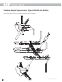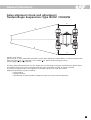
1
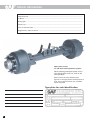
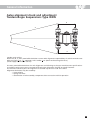
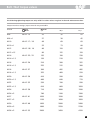
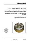
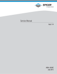
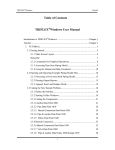
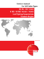
Service manual
for SAF Axles Types
SK RS / RZ 12242
K RZ / K ERZ 14242 / 16242
Leaf-Spring Suspensions
Tandem-Bogies
Edition 01/2006
Service
Vehicle information
Manufacturer.................................................................................................................................
Address...........................................................................................................................................
Body type.......................................................................................................................................
Chassis no.......................................................................................................................................
Year of manufacture ....................................................................................................................
Registration, date-in-service........................................................................................................
Spare parts service
for SAF axles and suspension systems.
When ordering spare parts quote correct
axle identification serial no., refer to the
axle type plate.
Please enter the axle identification
figures in the type plates shown below so
that correct specifications are available
when required.
Type plate for axle identification
2
Contents
This manual is intended for the technical workshop personnel responsible for maintenance and repair.
Page
SAF axle identification ..........................................................................................................................................2
General safety instructions ....................................................................................................................................5
Notes ............................................................................................................................7 / 20 / 37 / 44 / 49 / 54 / 60
SAF Axle Type SK RS / RZ / RZT 12242
Maintenance instructions . . . . . . . . . . . . . . . . . . . . . . . . . . . . . . . . . . . . . . . . . . . . . . . . . . . . . . . . . . . . . .8-9
Spare part illustrations / list of spare parts . . . . . . . . . . . . . . . . . . . . . . . . . . . . . . . . . . . . . . . . . . . . . .10-11
SAF Axle Type RZ / RZT / K RZ / K RZT / K ERZ / K ERZT / 14242 / 16242
Maintenance instructions . . . . . . . . . . . . . . . . . . . . . . . . . . . . . . . . . . . . . . . . . . . . . . . . . . . . . . . . . . . .12-13
Spare part illustrations / list of spare parts . . . . . . . . . . . . . . . . . . . . . . . . . . . . . . . . . . . . . . . . . . . . . .14-15
Brake – checking and adjustment . . . . . . . . . . . . . . . . . . . . . . . . . . . . . . . . . . . . . . . . . . . . . . . . . . . . . . . .16
Brake automatic slack-adjuster . . . . . . . . . . . . . . . . . . . . . . . . . . . . . . . . . . . . . . . . . . . . . . . . . . . . . . . .17-18
SAF Leaf-Spring Suspensions Type VB 9,000 - 30,000 kg (GL)
Maintenance instructions . . . . . . . . . . . . . . . . . . . . . . . . . . . . . . . . . . . . . . . . . . . . . . . . . . . . . . . . . . . . . . .21
Spare part illustrations / list of spare parts . . . . . . . . . . . . . . . . . . . . . . . . . . . . . . . . . . . . . . . . . . . . . .22-23
Torque setting . . . . . . . . . . . . . . . . . . . . . . . . . . . . . . . . . . . . . . . . . . . . . . . . . . . . . . . . . . . . . . . . . . . . . . . .24
SAF Leaf-Spring Suspensions Type VB 9,000 - 30,000 kg (ML)
Maintenance instructions . . . . . . . . . . . . . . . . . . . . . . . . . . . . . . . . . . . . . . . . . . . . . . . . . . . . . . . . . . . . . . .25
Spare part illustrations / list of spare parts . . . . . . . . . . . . . . . . . . . . . . . . . . . . . . . . . . . . . . . . . . . . . .26-27
Torque setting . . . . . . . . . . . . . . . . . . . . . . . . . . . . . . . . . . . . . . . . . . . . . . . . . . . . . . . . . . . . . . . . . . . . . . . .28
SAF Leaf-Spring Suspensions Type VB 9,000 - 30,000 kg (HD)
Maintenance instructions . . . . . . . . . . . . . . . . . . . . . . . . . . . . . . . . . . . . . . . . . . . . . . . . . . . . . . . . . . . . . . .29
Spare part illustrations / list of spare parts . . . . . . . . . . . . . . . . . . . . . . . . . . . . . . . . . . . . . . . . . . . . . .30-31
Torque setting . . . . . . . . . . . . . . . . . . . . . . . . . . . . . . . . . . . . . . . . . . . . . . . . . . . . . . . . . . . . . . . . . . . . . . . .32
SAF Leaf-Spring Suspensions Type VB 12,000 - 48,000 kg
Maintenance instructions . . . . . . . . . . . . . . . . . . . . . . . . . . . . . . . . . . . . . . . . . . . . . . . . . . . . . . . . . . . . . . .33
Spare part illustrations / list of spare parts . . . . . . . . . . . . . . . . . . . . . . . . . . . . . . . . . . . . . . . . . . . . . .34-35
Torque setting . . . . . . . . . . . . . . . . . . . . . . . . . . . . . . . . . . . . . . . . . . . . . . . . . . . . . . . . . . . . . . . . . . . . . . . .36
Installation Instructions for Leaf-Spring Suspensions Type VB . . . . . . . . . . . . . . . . . . . . . . . . . . . . . . .38-39
Important Information . . . . . . . . . . . . . . . . . . . . . . . . . . . . . . . . . . . . . . . . . . . . . . . . . . . . . . . . . . . . . . . . .40
Axle alignment check and adjustment . . . . . . . . . . . . . . . . . . . . . . . . . . . . . . . . . . . . . . . . . . . . . . . . . . . .41
Suspension installation, trailer slope . . . . . . . . . . . . . . . . . . . . . . . . . . . . . . . . . . . . . . . . . . . . . . . . . . . . . .42
3
Contents
Tandem-Bogie Suspensions Type IRUDZ 24,000 kg / 28,000 kg / 32,000 kg
Maintenance instructions . . . . . . . . . . . . . . . . . . . . . . . . . . . . . . . . . . . . . . . . . . . . . . . . . . . . . . . . . . . . . . .45
Spare part illustrations / list of spare parts . . . . . . . . . . . . . . . . . . . . . . . . . . . . . . . . . . . . . . . . . . . . . .46-47
Torque setting . . . . . . . . . . . . . . . . . . . . . . . . . . . . . . . . . . . . . . . . . . . . . . . . . . . . . . . . . . . . . . . . . . . . . . . .48
Tandem-Bogie Suspensions Type IRUDZW 32,000 kg
Spare part illustrations / list of spare parts . . . . . . . . . . . . . . . . . . . . . . . . . . . . . . . . . . . . . . . . . . . . . .50-51
Torque setting . . . . . . . . . . . . . . . . . . . . . . . . . . . . . . . . . . . . . . . . . . . . . . . . . . . . . . . . . . . . . . . . . . . . . . . .52
Axles alignment check and adjustment
Tandem-Bogie Suspensions Type IRUDZ / IRUDZW . . . . . . . . . . . . . . . . . . . . . . . . . . . . . . . . . . . . . . . . . . .53
Tandem-Bogie Suspensions Type IDZW 24,000 kg / 28,000 kg / 32,000 kg
Maintenance instructions . . . . . . . . . . . . . . . . . . . . . . . . . . . . . . . . . . . . . . . . . . . . . . . . . . . . . . . . . . . . . . .55
Spare part illustrations / list of spare parts . . . . . . . . . . . . . . . . . . . . . . . . . . . . . . . . . . . . . . . . . . . . . .56-57
Torque setting . . . . . . . . . . . . . . . . . . . . . . . . . . . . . . . . . . . . . . . . . . . . . . . . . . . . . . . . . . . . . . . . . . . . . . . .58
Axles alignment check and adjustment
Tandem-Bogie Suspensions Type IDZW . . . . . . . . . . . . . . . . . . . . . . . . . . . . . . . . . . . . . . . . . . . . . . . . . . . .59
General information
Bolt / Nut torque values . . . . . . . . . . . . . . . . . . . . . . . . . . . . . . . . . . . . . . . . . . . . . . . . . . . . . . . . . . . . . . . .61
The item numbers indicated are given only for identification and to distinguish between different versions.
Use the part numbers from the valid spare parts documents for identification of spare parts.
SAF axles and suspension units are subject to continuous further development; the data and drawings
contained in the manual may therefore vary in details.
The contents of the manual does not constitute the basis for a legal claim.
Reprinting, reproduction or translation in whole or in part is not permitted.
The issue of this publication invalidates all earlier maintenance and repair manuals.
4
General safety instructions
Please observe the following safety instructions in order to maintain the operational and road safety of your SAF
axles and suspension systems:
1.
The wheel contact surfaces between the wheel disc and wheel hub and the wheel nut contact surface at the wheel disc must
not be additionally painted. The contact surfaces must be clean, smooth and free from grease. Failure to observe this may result
in the wheel coming loose. Any additional instructions of the wheel manufacturer must also be observed.
2.
Only the wheel and tyre sizes approved by the trailer builder may be used. The tyres must always have the specified inflation
pressure.
3.
The brake systems of the tractor and the trailer/semi-trailer must be synchronised by means of a tractor/trailer brake
synchronisation not later than 5,000 km after the initial start of operation of the trailer/semi-trailer in order to ensure a safe
and uniform braking behaviour and uniform brake pad wear. Tractor/trailer brake synchronisations should be carried out by
appropriately qualified and equipped brake workshops.
The use of an additional braking system, such as a trailer anti-jackknife brake is forbidden by law on vehicles with type
approval after January 1999.
4.
Before starting a journey, ensure that the maximum permissible axle load is not exceeded and that the load is distributed
equally and uniformly.
5.
On trailers with air suspension, ensure that the air bags are completely filled with air before starting the journey. Incompletely
filled air bags may result in damage to axles, suspension, frame and superstructure and impair road safety.
6.
Ensure that the brakes are not overheated by continuous operation.
With drum brakes, overheating can result in a hazardous deterioration in the braking efficiency.
With disc brakes, overheating can result in damage to surrounding components – in particular the wheel bearings.
This can result in a significant deterioration in road safety, e.g. failure of wheel bearings.
7.
The parking brake must not be immediately applied when the brakes are hot, as the brake discs and brake drums may be
damaged by different stress fields during cooling.
8.
Use the supports provided when loading and unloading in order to avoid damage to the axle.
9.
Observe the operating recommendation of the trailer builder for off-road operation of the installed axles and suspension
systems.
The SAF definition of OFF-ROAD means driving on non-asphalted / non-concreted routes, such as e.g. gravel roads, agricultural
and forestry tracks, on construction sites and in gravel pits.
Off-road operation of SAF axles and suspension systems not designed for the purpose may result in damage and hence to an
impairment of road safety.
10.
SAF axles and suspension systems require continuous care, service and maintenance in order to maintain operational and road
safety and to be able to recognise natural wear and defects in good time.
The daily inspection of the trailer for road safety before starting the journey is one of the driver’s obligations.
SAF recommends that at least the inspections and maintenance operations described on page 6 should be carried out.
We recommend the use of original SAF spare parts.
A close-knit service network of SAF partner companies is available for the technical support of the SAF axles and suspension systems
and for the supply of original SAF spare parts (see rear cover or on the Internet under www.saf-axles.com).
Updates will be published as necessary on the Internet under www.saf-axles.com.
5
General service instructions
•
Caution: After every wheel change, always retighten the wheel nuts to the prescribed torque after 50 km and again after 150 km.
•
Check the brake lining thickness at regular intervals.
•
Carry out general visual inspections of the brakes, tyres and all suspension components at regular intervals and check for proper
attachment, wear, leaks, corrosion and damage.
•
Carry out regular visual inspections of the wheel bearing unit for grease leaks and axial clearance.
Wheel bearing grease change, see pages 9 and 13.
•
Regularly check the camshaft for smooth return and the slack adjuster for proper function.
•
Lubricate the camshaft at regular intervals.
•
Inspect the brake drum for wear* and cracking at every brake lining change.
Minimum wear limits*, see pages 9 and 13.
•
Replace the brake shoe return springs at every brake lining change.
•
On all units, check that the bolts of the U-brackets are tightened to the prescribed torques.
•
Carry out a general safety check in accordance with the statutory provisions.
•
We recommend the use of original SAF spare parts.
* We recommend that a general safety check is carried out when the minimum wear limit is reached.
6
NOTIZEN / NOTES / NOTE
7
Maintenance instructions
for SAF Axles Types SK RS/RZ/RZT 12242
for suspensions refer to separate maintenance chart
Service schedule
Mileage intervals
>
Time intervals
>
whichever comes first
Periodic checks
After first
5 000 km
every
every
every
or
15 000 km 90 000 km 150 000 km
After first
month
every
month
every
every
6 months 12 months
Mechanical check
Attention: Torque check wheel nuts after the first 50 km and
150 km (repeat also after every wheel removal).
Torque check all nuts and bolts to recommended setting.
Check and adjust hub end-float (if required).
•
•
•
•
•
Pack wheel bearings with fresh grease after 300,000 km or
36 months, whichever comes first. Check condition of taper roller
bearings and replace, if necessary.
•
•
•
•
•
Check brake lining to drum clearance for correct adjustment
readjust clearance if necessary.
Check service brake and parking brake for performance.
•
•
Check truck-trailer combination for compatibiliy
of service brake pessure.
Check service brake pressure to manufacturer’s specification.
Adjust LSV output pressure, if found incorrect setting.
•
Check suspension ride height in laden condition if excessive trailer
slope is obvious consult trailer manufacturer repeat check of
trailer slope after every tractor interchanging.
•
Lubricate camshaft bearing bushs.
Lubricate suspension components, follow to individual suspension
type maintenance instructions.
Visual inspection
•
for wear / damage
Check suspension components for wear and damage
Check brake linings for wear
Check camshafts for free rotation
Check slack adjusters for correct function
Check air brake system for leaks (brake applied)
Check leaf springs for damage, scoring and corrosion
Check tyres for uneven wear and axles for correct tracking
do readjustment if necessary
Safety inspection
•
Special service conditions
Vehicles with long standing periods:
service at specified time intervals
Vehicles used under extreme conditions:
service at suitably reduced intervals
e.g.: Trailer operating in continous multi-shifts or in off-road constructions sites.
Warranty claims will only be accepted as long as the operating and maintenance instructions have been
complied with and if SAF approved spare parts have been fitted.
8
Maintenance instructions
for SAF Axles Types SK RS/RZ/RZT 12242
Hub end-float setting
Lubricant specification:
Tighten hub nut (22) to a torque of 150 Nm at the
same time rotating the hub and drum.
Wheel bearings:
SAF parts no. 4 387 0011 05
Locate the locking collar (23) onto the dowel on the
hub nut noting the position of the dowel in relation
to the collar. Remove the collar and turn the hub
nut 2 1/2 holes anti-clockwise. Reverse the collar and
re-locate it onto the repositioned hub nut dowel.
Camshaft:
SAF parts no. 4 387 0011 05
Stub axle:
SAF parts no. 4 387 0015 06
SAF fitting paste
Fit the lock nut (24) and tighten using a torque of
400 Nm.
Brake anchor bracket ball:
SAF parts no. 4 387 0007 00
Copper paste
Check whether the hub rotates freely and without
excessive end-float (repeat adjustment if necessary).
Replace O-ring (39) and fit the hub cap.
Never mix different types or grades
of grease!
BRAKE type SNK 420
Brake drum diameter max. limit for remachining:
Brake drum diameter max. limit of wear:
Brake linings approved by SAF:
Machine new brake lining surface to brake drum diameter + 0.3 mm.
When relining brakes, fit cam-side and anchor-side lining following the
replacement kit.
Brake
size
SAF parts no.
brake lining /
rivet kit
SNK 420
Brake drum / brake lining
refacing stages in mm
1st oversize
2nd oversize
d0-420.0
d1-422.0
d2-424.0
424.0
d2
2nd
oversize
2. Rep.-Stufe
instructions provided with the
Rivets
number per axle
x 180
3 057 0060 00
20.6
20.0
21.6
21.0
22.6
22.0
4
4
x 200
3 057 0066 00
20.6
20.0
21.6
21.0
22.6
22.0
4
4
Assembly tools
Hub nut spanner
Hub puller
Universal hub puller
Wheel bearing and seal inserter
Brake shoe clamping device
422.0
424.0 mm
425.0 mm
BERAL 1541, BREMSKERL 6386
Brake linings
size
d1
1st
oversize
1. Rep.-Stufe
d0
nominal
size
Normalmaß
After brake relining, lubricate camshaft
bearings whilst rotating the camshaft
through 360º several times.
Do not disassemble the hub bearing
assembly.
Use a vacuum cleaner to remove brake dust.
Never use pressurised cleaning devices or
cleaning fluids on the brake drum and hub.
Clean stub axle and apply fresh SAF fitting
paste.
420.0
Hub nut tightening
64
DIN 7338
rivet
B 8 x 15
SAF parts no.
2 012 0023 01
3 301 0010 00
4 434 3822 00
3 434 3308 00
3 349 1001 00
9
Spare part illustrations
Exploded view of SAF Axles Types SK RS/RZ/RZT 12242
Torque wrench settings
Use a torque wrench.
The use of impact wrenches
is not accepted.
Wheel nuts:
Spigot-hub-centred fixing:
M 22 x 1.5 / 600 Nm
Bolt-centred fixing:
M 22 x 2 / 430 Nm
M 22 x 1.5 / 430 Nm
TRILEX-Spoked wheels fixing:
Tyre 20”+24”
M 20 / 350 Nm
091
98
97
96
94
92
93
94
29
77
37
95
35
091
99
98
94
96
97
92
27
93
36
39
29
40
42
77
37
95
35
30
31
38
99
94
27
40
38.2
39
34
38.1
36
89.1
081/082
41
87
88
90
88.1
18,3
86
85.1
89
64
75
66
65
70
7372
71
89.2
89.3
010
18
12
74
15
18
6.1
Typenschild
Type
plate
059
6.2 6
25
3
24
23
22
80.2
5
78
01
80.1
80.3
10
Production number
RH side (driving direction)
List of spare parts
SK RS/RZ/RZT 12242
Item
Parts designation
Item
Parts designation
01
Axle beam assembly
including items 3-25
Mounting plate
Anchor ball
65
Brake shoe
including item 66
Cam roller
3
5
66
70
06
6
6.1
6.2
010
Camshaft bearing kit
including items 6, 6.1, 6.2
Cam bearing unit
Anchor bracket
Bolt
Lock nut
11
15
18
Camshaft bearing kit
including items 11, 15, 18
Cam bearing unit
Bolt
Rubber dust cover
18.3
22
23
24
25
Lining wear indicator
Axle nut
Lock plate
Axle nut
Brake chamber support
27
Hub assembly
including items 35-38.2
29
Brake drum
30
31
34
35
36
Wheel bolt kit
including items 31-34
Wheel bolt
Wheel nut
Tapper roller bearing
Tapper roller bearing
37
38
38.1
38.2
39
Unitised seal
Seal plate, inner
Spacer plate
Seal plate, outer
O-ring
40
41
Hub cap kit
including items 39-41
Protection plug
059
Brake components
64
Brake shoe assembly with linings
including items 65, 71-73
71
72
73
Brake lining kit
including items 71-73
Brake lining, cam side
Brake lining, anchor side
Rivet
74
75
77
Retaining clamp
Release spring
ABV Exciter gear
78
80.1
80.3
Sensor
Cable hose
Clip
081
Camshaft kit, LH
including items 85-88.1, 18.3
082
85
86
87
88
88.1
Camshaft kit, RH
including items 85-88.1, 18.3
Disc spring
Retaining ring
Washer
Washer
Retaining ring
89
90
Slack adjuster
Release spring
89.1
89.2
89.3
with automatic adjustment
Slack adjuster, automatic
Bracket, LH
Bracket, RH
091
92
93
94
95
96
97
98
Dust cover kit
including items 92-99
Dust cover RH
Dust cover LH
Rubber plug
Cable clip
Fastener clip bolt
Clip
Rubber plug
When ordering spare parts quote correct axle identification serial no., refer to the axle type plate.
11
Maintenance instructions
for SAF Axles Types RZ/RZT/K RZ/K RZT/K ERZ/K ERZT/14242/16242
for suspensions refer to separate maintenance chart
Service schedule
Mileage intervals
>
Time intervals
>
whichever comes first
Periodic checks
After first
5 000 km
every
every
every
or
15 000 km 90 000 km 150 000 km
After first
month
every
month
every
every
6 months 12 months
Mechanical check
Attention: Torque check wheel nuts after the first 50 km and
150 km (repeat also after every wheel removal).
Torque check all nuts and bolts to recommended setting.
Check and adjust hub end-float (if required).
•
•
•
•
•
Pack hub bearings with fresh grease (also after every brake lining
replacement, check hub bearing wear).
•
•
•
•
•
•
Check brake lining to drum clearance for correct adjustment
readjust clearance if necessary.
Check service brake and parking brake for performance.
•
•
Check truck-trailer combination for compatibiliy of service brake
pessure.
Check service brake pressure to manufacturer’s specification.
Adjust LSV output pressure, if found incorrect setting.
•
Check suspension ride height in laden condition if excessive trailer
slope is obvious consult trailer manufacturer repeat check of
trailer slope after every tractor interchanging.
•
Lubricate camshaft bearing bushs.
Lubricate suspension components, follow to individual suspension
type maintenance instructions.
Visual inspection
•
for wear / damage
Check suspension components for wear and damage
Check brake linings for wear
Check camshafts for free rotation
Check slack adjusters for correct function
Check air brake system for leaks (brake applied)
Check leaf springs for damage, scoring and corrosion
Check tyres for uneven wear and axles for correct tracking
do readjustment if necessary
Safety inspection
•
Special service conditions
Vehicles with long standing periods:
service at specified time intervals
Vehicles used under extreme conditions:
service at suitably reduced intervals
e.g.: Trailer operating in continous multi-shifts or in off-road constructions sites.
Warranty claims will only be accepted as long as the operating and maintenance instructions have been
complied with and if SAF approved spare parts have been fitted.
12
Maintenance instructions
for SAF Axles Types RZ/RZT/K RZ/K RZT/K ERZ/K ERZT/14242/16242
Hub end-float setting
Lubricant specification:
Tighten hub nut while at the same time turning the
hub until slight resistance is felt.
Wheel bearings:
SAF parts no. 4 387 0011 05
Now slacken the hub nut by 1/12 of a turn until the
next locking position is reached. Secure with split
pin.
Camshaft:
SAF parts no. 4 387 0011 05
Insert hub puller and pull hub back to the outer
bearing.
Stub axle:
SAF parts no. 4 387 0015 06
SAF fitting paste
Hub cap thread with sealing compound and refit
hub cap.
Brake anchor bracket ball:
SAF parts no. 4 387 0007 00
Copper paste
Check whether the hub rotates freely and without
excessive end-float (repeat adjustment if necessary).
Never mix different types or grades
of grease!
Hub nut tightening
BRAKE type SNK 420
Brake drum diameter max. limit for remachining:
Brake drum diameter max. limit of wear:
Brake linings approved by SAF:
Machine new brake lining surface to brake drum diameter + 0.3 mm.
When relining brakes, fit cam-side and anchor-side lining following the
replacement kit.
Brake
size
1st oversize
2nd oversize
d0-420.0
d1-422.0
d2-424.0
3 057 0060 00
20.6
20.0
21.6
21.0
22.6
22.0
4
4
x 200
3 057 0066 00
20.6
20.0
21.6
21.0
22.6
22.0
4
4
SAF parts no.
14242
1 012 0013 00 B
3 301 0006 02
4 434 3822 00
4 434 3815 00
3 434 3300 00
3 349 1001 00
1 434 1056 00
1 434 1055 00
424.0
d2
2nd
oversize
2. Rep.-Stufe
Rivets
number per axle
x 180
Assembly tools
Axle types
Hub nut spanner and cap spanner
Hub puller
Universal hub puller
Bearing inner race inserter
Wheel bearing and seal inserter
Brake shoe clamping device
Camshaft bushing tool
Camshaft bushing tool
422.0
instructions provided with the
Brake linings
size
d1
1st
oversize
1. Rep.-Stufe
424.0 mm
425.0 mm
BERAL 1541, BREMSKERL 6386
Brake drum / brake lining
refacing stages in mm
SAF parts no.
brake lining /
rivet kit
SNK 420
d0
nominal
size
Normalmaß
Use a vacuum cleaner to remove brake dust.
Never use pressurised cleaning devices or
cleaning fluids on the brake drum and hub.
Clean stub axle and apply fresh SAF fitting
paste.
420.0
After brake relining, lubricate camshaft
bearings whilst rotating the camshaft
through 360º several times.
64
16242
1 012 0013
3 301 0007
4 434 3822
4 434 3816
3 434 3301
3 349 1001
1 434 1056
1 434 1055
DIN 7338
rivet
B 8 x 15
00 B
01
00
00
00
00
00
00
13
Spare part illustrations
Exploded view of SAF Axles Types
RZ/RZT/K RZ/K RZT/K ERZ/K ERZT/14242/16242
Torque wrench settings
Use a torque wrench.
The use of impact wrenches
is not accepted.
Wheel nuts:
Spigot-hub-centred fixing:
M 22 x 1.5 / 600 Nm
Bolt-centred fixing:
M 22 x 2 / 430 Nm
M 22 x 1.5 / 430 Nm
091
98
97
TRILEX-Spoked wheels fixing:
Tyre 20”+24”
M 20 / 350 Nm
96
94
92
94
93
29
77
37
95
35
091
99
94
98
97
96
92
93
27
36
40
29
77
95
37
35
30
32
99
27
94
31
90
34
89.1
36
40
081/082
87
88.1
18.3
86
85.1
28
85
84
84.1
64
70
73
66
88
89
72
89.2
89.3
71
65
010
75
18
12
74
15
18
8
Type
plate
Typenschild
059
6
25
3
23
80.2
22
21
5
78
01
80.1
14
80.3
Production number
RH side (driving direction)
List of spare parts
RZ/RZT/K RZ/K RZT/K ERZ/K ERZT/14242/16242
Item
Parts designation
Item
Parts designation
01
Axle beam assembly
including items 3-25
Mounting plate
Anchor ball
Bronze bush
Grease nipple
73
74
75
77
78
Rivet
Retaining clamp
Release spring
Exciter gear
Sensor ABS
80.1
80.2
80.3
Cable hose
Clip
Clip
081
Camshaft kit, LH
including items 84-88.1, 18.3
082
84
84.1
85
85.1
86
87
88
88.1
Camshaft kit, RH
including items 84-88.1, 18.3
O-ring
Distance ring
Grease seal
Disc spring
Retaining clamp
Washer
Washer
Retaining clamp
89
Slack adjuster
89.1
89.2
89.3
with automatic ajustment
Slack adjuster, automatic
Bracket, LH
Bracket, RH
90
Release spring
091
Dust cover kit
including items 92-99
Dust cover RH
Dust cover LH
Rubber plug
Cable clip
Fastener clip bolt
Clip
Rubber plug
3
5
6
8
010
11
15
18
Camshaft bearing kit
including items 11, 15, 18
Cam bearing unit
Bolt
Rubber dust cover
18.3
21
22
23
25
Wearing gauge
Wear ring
Axle nut
Split pin
Brake chamber support
27
28
29
Hub, including item 28
Grooved pin
Brake drum
30
31
32
34
Wheel bolt kit
including items 31-34
Wheel bolt
Hex nut
Wheel nut
35
36
37
40
Tapper roller bearing
Tapper roller bearing
Grease seal
Hub cap
059
Brake components
64
Brake shoe assembly with linings
including items 65, 71-73
65
Brake shoe
including item 66
Cam roller
66
70
71
72
92
93
94
95
96
97
98
Brake lining kit
including items 71-73
Brake lining, cam side
Brake lining, anchor side
When ordering spare parts quote correct axle identification serial no., refer to the axle type plate.
15
General information
Brake – checking and adjustment
S-cam brakes with manual slack adjusters
Due to normal brake drum and brake lining wear, the wheel brakes must be regularly adjusted in order to
maintain the full brake performance. To ensure maximum brake efficiency, the clearance between brake lining
and drum must be kept to an absolute minimum. To determine this clearance, check the brake chamber stroke
while full pressure is applied to the service brake. If the push rod movement is more than 2/3 of the maximum
chamber stroke then the brake must be adjusted. With a correctly adjusted brake, the push rod movement is
not more than 15 mm.
Turn adjusting screw to the
right until...
... the brake lining contacts
closely to the brake drum.
In brake released
position no push
rod movement
ist permissible.
Turn adjusting screw to the
left, until...
... the push rod movement
(at 127 mm) is approx.
10 - 15 mm.
Adjusting screw
(spanner size 19 mm)
The wheel must rotate freely
with no grating noise.
Special instructions for automatic slack adjusters are given on the following pages.
A = At 1/2 push rod stroke, the angle must remain more than 90°.
B = On full brake application, the slack adjuster housing should have clearance to the axle
beam.
L = Check push rod length in accordance with SAF specification.
16
General information
Automatic slack adjuster
Type HALDEX
When interchanging from a manual to an automatic slack adjuster, make sure that you fitt replacement
adjuster in accordance with type approval by SAF for your specific axle type.
Changes to the adjuster arm length are not permissible.
NOTE: The installation of an incorrect type of automatic slack adjuster will
result in critical effect of serious overheating the brakes.
References regarding automatic slack adjuster to SAF axles types are
available from your SAF service partner at request (see back cover).
17
General information
Automatic slack adjuster – Type HALDEX
L
10
7
1
2
4
3
2
• Turn adjusting screw (1) until the bore in the slack
adjuster (8.1) coincides with the bore in the clevis
end (9) (see drawing).
• Grease split pin (8) and secure.
• Install return spring (10).
11
• Move the control arm (2) in the direction of the
arrow (operating direction of slack adjuster) up to
its end position “A” without applying excessive
force.
• When control arm (2) is in its end position “A”,
tighten the fixing bolts (4).
• Set cams and brake shoes to released position.
• Observe the correct push rod length “L” as
indicated in the SAF specifications.
• Membrane brake chamber
Before installing the automatic slack adjuster,
ensure that the brake chamber push rod is in
released position.
• By contrast, spring brake chambers must be under
full operating pressure (min. 6 bar).
IMPORTANT: If this is not maintained properly, the
basic setting will be wrong, with critical effect of
overheating the brakes.
• Grease the camshaft.
• Install anchor bracket (3), being sure to use two
fixing bolts (4), do not yet tighten the bolts.
• Install the slack adjuster on the camshaft.
• The arrow (7) points in the braking direction.
18
• For the anchor bracket mounting (11), ensure that
the 2 U-profiles engage firmly together.
• Fit slack adjuster retaining clip on camshaft.
• Axial clearance: Adjust 0.5 - 2 mm using shims.
• Adjust running clearance between brake lining and
drum by turning adjusting screw (1) in clockwise
direction until the lining fits smoothly against the
drum. Then back off adjusting screw (1) by 3/4 turn.
Do not use impact wrenches!
FUNCTION CHECK
• If the self adjuster is functioning correctly, then
a minimum torque of 18 Nm must be felt and a
grating noise must be heard when adjusting screw
(1) is backed off.
• Operate the footbrake several times. Check whether
the brake drum rotates freely, check the lining
clearance and repeat adjustment procedure if
necessary.
Leaf-Spring
Suspensions
19
NOTIZEN / NOTES / NOTE
20
Maintenance instructions
Leaf-Spring Suspensions Type VB 9,000 kg - 30,000 kg (GL)
for axles refer to separate maintenance chart
Service schedule
Mileage intervals
>
Time intervals
>
whichever comes first
Periodic checks
After first
5 000 km
every
every
every
or
15 000 km 90 000 km 150 000 km
After first
month
every
month
every
every
6 months 12 months
Mechanical check
Torque check all nuts and bolts to recommended setting.
Follow exploded view items
Visual inspection
•
•
for wear / damage
Check suspension components for wear and damage
•
•
Safety inspection
Check suspension ride height in laden condition if excessive trailer
slope is obvious, consult trailer manufacturer.
Repeat check also after every tractor interchanging.
•
Special service conditions
Vehicles with long standing periods:
service at specified time intervals
Vehicles used under extreme conditions:
service at suitably reduced intervals
e.g.: Trailer operating in continous multi-shifts or in off-road constructions sites.
Warranty claims will only be accepted as long as the operating and maintenance instructions have been
complied with and if SAF approved spare parts have been fitted.
21
109
22
103
107.1
106
107
106
108
105
201
205
108
203
122
117
109
103
120
105
207
116
114
106
201
205
203
108
207
201
121
123
108
115
122
122
116
117
121
116
117
120
116 115
112 109
108
119
107.1
109
107
106
116 115
123
121
123
138
130
138
137
205
127
135
131
136
133
129
133
136
122
203
135
106
201
108
109
121
120
116
114
117
119
116 115
107
207
107.1
106
adjustable torque arm kit
112
108
109
105
137
136
133
128
133
136
116 109
120
205
203
123
104
207
105
107.1
107
133
126
138
133
136
135
137
136
133
109
rigid torque arm kit
137
136
138
108
106
136
135
IPL_08_050-0
133
104
Spare part illustrations
Leaf-Spring Suspensions Type VB 9,000 kg - 30,000 kg (GL)
Rubber bushing rocker shaft
Tri-axle suspension
Assembly of Tri-axle suspension are basically the same components as for the tandem suspension.
Repeat check maintenance instructions by similar procedure for the Tri-axle suspension components.
Ref. No.: IPL_08_050-0
List of spare parts
Leaf-Spring Suspensions Type VB 9,000 kg - 30,000 kg (GL)
Item
Parts designation
Item
Parts designation
101
Hanger bracket kit, front
including items 103, 105-109
124
Adjustable torque arm kit
including items 126, 133, 134
Hanger bracket kit, rear
including items 104, 105-109
103
Front hanger bracket
104
Rear hanger bracket
105
Slider
106
Slide link
107
Distance sleeve
107.1 Rubber bush
108
Hex bolt
109
Lock nut
112
Hanger bracket
126
127
Torque arm rigid
Adjuster
128
Torque arm end, LH-Threat
including items 130-131
129
Torque arm end, RH-Threat
including items 130-131
Hex bolt
Lock nut
Rubber bush
113
Rocker arm kit
including items 108-109, 114-118
Rocker arm
Sliding block
Slide link
Distance sleeve
134
135
136
137
138
Bolt kit
including items 135-138
Hex bolt
Washer
Castle nut
Split pin
Rocker shaft kit
including items 119-123
Rocker shaft
Rubber bush
Washer
Castle nut
Split pin
201
203
205
206
207
Spring
Clamping plate
U-bolt
Distance sleeve
Hex nut
102
114
115
116
117
118
119
120
121
122
123
130
131
133
When ordering spare parts quote correct axle identification serial no., refer to the axle type plate.
23
Torque setting
Leaf-Spring Suspensions Type VB 9,000 kg - 30,000 kg (GL)
Rubber bushing rocker shaft
Use a torque wrench. The use of impact wrenches is not accepted.
IPL_25_05
M30 350 Nm
M30 350 Nm
rigid torque arm assembly
M48 850 Nm
M30 350 Nm
M30 350 Nm
M30 350 Nm
M14 105 Nm
24
M24 600 Nm
M48 850 Nm
M14 105 Nm
M14 105 Nm
M14 105 Nm
M30 350 Nm
M24 600 Nm
M14 105 Nm
Tri-axle suspension
Assembly of Tri-axle suspension are basically the same components as for the tandem suspension.
Repeat check maintenance instructions by similar procedure for the Tri-axle suspension components.
Ref. No.: IPL_25_050-0
Maintenance instructions
Leaf-Spring Suspensions Type VB 9,000 kg - 30,000 kg (ML)
for axles refer to separate maintenance chart
Service schedule
Mileage intervals
>
Time intervals
>
whichever comes first
Periodic checks
After first
5 000 km
every
every
every
or
15 000 km 90 000 km 150 000 km
After first
month
every
month
every
every
6 months 12 months
Mechanical check
Torque check all nuts and bolts to recommended setting.
Follow exploded view items.
Lubricate rocker-arm shaft bushs.
Visual inspection
•
•
•
•
•
•
for wear / damage
Check suspension components for wear and damage.
Safety inspection
Check suspension ride height in laden condition if excessive trailer
slope is obvious, consult trailer manufacturer.
Repeat check also after every tractor interchanging.
•
Special service conditions
Vehicles with long standing periods:
service at specified time intervals
Vehicles used under extreme conditions:
service at suitably reduced intervals
e.g.: Trailer operating in continous multi-shifts or in off-road constructions sites.
Warranty claims will only be accepted as long as the operating and maintenance instructions have been
complied with and if SAF approved spare parts have been fitted.
25
109
26
103
107.1
106
107
106
108
105
201
205
108
203
119
120
120.2
121
117
107.1
109
107
205
201
108
203
123.1
115
120.1
207
116
117
120.1
120.2
116 115
138
130
137
138
127
136
109
122
135
131
135
123
203
133
129
133
136
121
205
106
201
108
120
107
207
107.1
106
adjustable torque arm kit
114
112
108
105
109
137
136
133
128
133
136
116 109
120.2
201
108
120
116
117
119
116
117
108
116 115
112 109
106
105
207
116
114
120.2
120
120.1
106
116 115
109
103
122
123
205
203
104
137
136
138
108
107.1
107
109
133
126
138
133
136
137
133
106
135
136
rigid torque arm kit
207
105
136
135
IPL_08_060-0
133
104
Spare part illustrations
Leaf-Spring Suspensions Type VB 9,000 kg - 30,000 kg (ML)
Bronze bushing rocker shaft
Tri-axle suspension
Assembly of Tri-axle suspension are basically the same components as for the tandem suspension.
Repeat check maintenance instructions by similar procedure for the Tri-axle suspension components.
Ref. No.: IPL_08_060-0
List of spare parts
Leaf-Spring Suspensions Type VB 9,000 kg - 30,000 kg (ML)
Item
Parts designation
Item
Parts designation
101
Hanger bracket kit, front
including items 103, 105-111
125
102
Hanger bracket kit, rear
including items 104, 105-111
Front hanger bracket
Rear hanger bracket
Slide link
Slide link
Distance sleeve
Hex bolt
Lock nut
Hex bolt
Lock nut
Hanger bracket
Torque arm adjustable kit
including items 127, 128-131, 133.1, 134
Torque arm rigid
Adjuster (210 mm)
103
104
105
106
107
108
109
110
111
112
113
Rocker arm kit
including items 107-109, 114-118
114
Rocker arm
116
Slide link
117
Hex bolt
117.1 Washer
117.2 Lock nut
126
127
128
Torque arm end, LH-Threat
including items 128.1, 130-131
128.1 Grease nipple
129
130
131
Torque arm end, RH-Threat
including items 128.1, 130-131
Hex bolt
Lock nut
133
135
136
137
138
Rubber bush
Bolt
Washer
Castle nut
Split pin
201
203
205
207
Leaf spring
Clamping plate
U-bolt
Hex nut
118
Rocker shaft kit
including items 119-123.1
119
Rocker shaft
120
Rubber bush
120.1 Washer
120.2 Bronze bush
121
Washer
122
Castle nut
123
Split pin
123.1 Grease nipple
When ordering spare parts quote correct axle identification serial no., refer to the axle type plate.
27
Torque setting
Leaf-Spring Suspensions Type VB 9,000 kg - 30,000 kg (ML)
Bronze bushing rocker shaft
Use a torque wrench. The use of impact wrenches is not accepted.
IPL_25_06
M30 350 Nm
M30 350 Nm
rigid torque arm assembly
28
M30 350 Nm
M30 350 Nm
M14 105 Nm
M24 600 Nm
M30 350 Nm
M14 105 Nm
M30 350 Nm
M48 1100 Nm
M14 105 Nm
M14 105 Nm
M24 600 Nm
M14 105 Nm
Tri-axle suspension
Assembly of Tri-axle suspension are basically the same components as for the tandem suspension.
Repeat check maintenance instructions by similar procedure for the Tri-axle suspension components.
Ref. No.: IPL_25_060-0
Maintenance instructions
Leaf-Spring Suspensions Type VB 9,000 kg - 30,000 kg (HD)
for axles refer to separate maintenance chart
Service schedule
Mileage intervals
>
Time intervals
>
whichever comes first
Periodic checks
After first
5 000 km
every
every
every
or
15 000 km 90 000 km 150 000 km
After first
month
every
month
every
every
6 months 12 months
Mechanical check
Torque check all nuts and bolts to recommended setting.
Follow exploded view items.
Lubricate rocker-arm shaft bushs.
Visual inspection
•
•
•
•
•
•
for wear / damage
Check suspension components for wear and damage.
Safety inspection
Check suspension ride height in laden condition if excessive trailer
slope is obvious, consult trailer manufacturer.
Repeat check also after every tractor interchanging.
•
Special service conditions
Vehicles with long standing periods:
service at specified time intervals
Vehicles used under extreme conditions:
service at suitably reduced intervals
e.g.: Trailer operating in continous multi-shifts or in off-road constructions sites.
Warranty claims will only be accepted as long as the operating and maintenance instructions have been
complied with and if SAF approved spare parts have been fitted.
29
107
106
105
122
30
106
108
110
121
120.1
120
120.1
135.1
103
120
106
110
137
135
108
109
111
116
110.1
135.1
201
205
203
107.1
207
114
108
108
110.1
103.1
111
137
106
109
105
201
205
203
126
137
107
135
123.1
111
137
109
119
118
rocker shaft kit
112
109
135.2
126 / 126.1
116
137 109
107.1
207
111
114
111
109
107.1 135
116
201
205
203
135.2
137
207
137
129
133
130
125 / 125.1
127
133
135
135
104
135.1 /135.2
131
137
128
201
205
203
107 106
adjustable torque arm kit
108
112.1
110.1
110.1
106
105
108
116
107.1
137
111
110
108
109
106
105
109
111
207
133
124 / 124.1
135.1 /135.2
137
IPL_08_075_
135
108 110
133
106
126 / 126.1
104
107
rigid torque arm kit
137
111
Spare part illustrations
Leaf-Spring Suspensions Type VB 9,000 kg - 30,000 kg (HD)
Bronze bushing rocker shaft
Tri-axle suspension
Assembly of Tri-axle suspension are basically the same components as for the tandem suspension.
Repeat check maintenance instructions by similar procedure for the Tri-axle suspension components.
Ref. No.: IPL_08_075_0
List of spare parts
Leaf-Spring Suspensions Type VB 9,000 kg - 30,000 kg (HD)
Item
Parts designation
Item
Parts designation
101
Hanger bracket kit, RH, front
including items 103, 105-111
124
Torque arm rigid kit
125
Torque arm adjustable kit
126
127
128
129
130
131
133
135
135.1
135.2
137
Torque arm
Adjuster
Torque arm end, LH-Threat
Torque arm end, RH-Threat
Hex bolt
Lock nut
Rubber bush
Hex bolt
Hex bolt
Hex bolt
Lock nut
201
203
205
207
Leaf spring
Clamping plate
U-bolt
Hex nut
101.1 Hanger bracket kit, LH, front
including items 103.1, 105-111
102
103
103.1
104
105
106
107
107.1
108
109
110
110.1
111
112
112.1
Hanger bracket kit, rear
including items 104, 105-111
Front hanger bracket, RH
Front hanger bracket, LH
Rear hanger bracket
Slider
Slide link
Distance sleeve
Distance sleeve
Hex bolt
Lock nut
Hex bolt
Hex bolt
Lock nut
Hanger bracket, RH
Hanger bracket, LH
114
116
Rocker arm
Slide link
118
Rocker shaft kit
including items 119-123.1
119
Rocker shaft
120
Bronze bush
120.1 Washer
121
Washer
122
Lock nut
123.1 Grease nipple
When ordering spare parts quote correct axle identification serial no., refer to the axle type plate.
31
Torque setting
Leaf-Spring Suspensions Type VB 9,000 kg - 30,000 kg (HD)
Bronze bushing rocker shaft
Use a torque wrench. The use of impact wrenches is not accepted.
x M36 (1400 Nm)
M14 (105 Nm)
x M36 (1400 Nm)
M14 (105 Nm)
M24 (600 Nm)
M14 (105 Nm)
M14 (105 Nm)
M20 (320 Nm)
x M36 (1400 Nm)
x M36 (1400 Nm)
32
M20 (320 Nm)
x M36 (1400 Nm)
x M36 (1400 Nm)
x M42x3 (2200 Nm)
M20 (320 Nm)
M14 (105 Nm)
x M36 (1400 Nm)
M24 (600 Nm)
M14 (105 Nm)
x M36 (1400 Nm)
M14 (105 Nm)
x M36 (1400 Nm)
M20 (320 Nm)
M24 (600 Nm)
M42x3 (2200 Nm)
Tri-axle suspension
Assembly of Tri-axle suspension are basically the same components as for the tandem suspension.
Repeat check maintenance instructions by similar procedure for the Tri-axle suspension components.
Ref. No.: IPL_25_002-0
Maintenance instructions
Leaf-Spring Suspensions Type VB 12,000 kg - 48,000 kg
for axles refer to separate maintenance chart
Service schedule
Mileage intervals
>
Time intervals
>
whichever comes first
Periodic checks
After first
5 000 km
every
every
every
or
15 000 km 90 000 km 150 000 km
After first
month
every
month
every
every
6 months 12 months
Mechanical check
Torque check all nuts and bolts to recommended setting.
Follow exploded view items.
Lubricate rocker-arm shaft bushs.
Visual inspection
•
•
•
•
•
•
for wear / damage
Check suspension components for wear and damage.
Safety inspection
Check suspension ride height in laden condition if excessive trailer
slope is obvious, consult trailer manufacturer.
Repeat check also after every tractor interchanging.
•
Special service conditions
Vehicles with long standing periods:
service at specified time intervals
Vehicles used under extreme conditions:
service at suitably reduced intervals
e.g.: Trailer operating in continous multi-shifts or in off-road constructions sites.
Warranty claims will only be accepted as long as the operating and maintenance instructions have been
complied with and if SAF approved spare parts have been fitted.
33
107
106
105
122
34
106
108
110
120
120.1
135.1
103
121
120.1
120
137
109
107
106
110
137
135.1
201
205
203
107.1
207
114
108
108
110.1
103.1
111
137
106
109
105
201
205
203
126
137
123.1
111
135
119
118
rocker shaft kit
135
108
109
111
116
110.1
112
109
135.2
116
112.1
110.1
108
110.1
137
107.1
116
111
106
105
137
129
133
130
125 / 125.1
127
201
205
203
107 106
109
135
135
104
135.1 /135.2
131
137
128
133
135.2
207
adjustable torque arm kit
108
126 / 126.1
137 109
107.1
207
111
114
111
109
107.1 135
116
201
205
203
110
108
111
111
207
137
133
124 / 124.1
104
133
108 110
135.1 /135.2
135
IPL_08_070_0
126 / 126.1
106
137
107
rigid torque arm kit
106
105
109
Spare part illustrations
Leaf-Spring Suspensions Type VB 12,000 kg - 48,000 kg
Bronze bushing rocker shaft
Tri-axle suspension
Assembly of Tri-axle suspension are basically the same components as for the tandem suspension.
Repeat check maintenance instructions by similar procedure for the Tri-axle suspension components.
Ref. No.: IPL_08_070_0
List of spare parts
Leaf-Spring Suspensions Type VB 12,000 kg - 48,000 kg
Item
Parts designation
Item
Parts designation
101
Hanger bracket kit, RH, front
including items 103, 105-111
124
Torque arm rigid kit
125
Torque arm adjustable kit
126
127
128
129
130
131
133
135
135.1
135.2
137
Torque arm
Adjuster
Torque arm end, LH-Threat
Torque arm end, RH-Threat
Hex bolt
Lock nut
Rubber bush
Hex bolt
Hex bolt
Hex bolt
Lock nut
201
203
205
207
Leaf spring
Clamping plate
U-bolt
Hex nut
101.1 Hanger bracket kit, LH, front
including items 103.1, 105-111
102
103
103.1
104
105
106
107
107.1
108
109
110
110.1
111
112
112.1
Hanger bracket kit, rear
including items 104, 105-111
Front hanger bracket, RH
Front hanger bracket, LH
Rear hanger bracket
Slider
Slide link
Distance sleeve
Distance sleeve
Hex bolt
Lock nut
Hex bolt
Hex bolt
Lock nut
Front hanger bracket, RH
Front hanger bracket, LH
114
116
Rocker arm
Slide link
118
Rocker shaft kit
including items 119-123.1
119
Rocker shaft
120
Bronze bush
120.1 Washer
121
Washer
122
Lock nut
123.1 Grease nipple
When ordering spare parts quote correct axle identification serial no., refer to the axle type plate.
35
Torque setting
Leaf-Spring Suspensions Type VB 12,000 kg - 48,000 kg
Bronzce bushing rocker shaft
Use a torque wrench. The use of impact wrenches is not accepted.
x M36 (1400 Nm)
M14 (105 Nm)
x M36 (1400 Nm)
M14 (105 Nm)
M24 (600 Nm)
M14 (105 Nm)
M14 (105 Nm)
M20 (320 Nm)
x M36 (1400 Nm)
x M36 (1400 Nm)
36
M20 (320 Nm)
x M36 (1400 Nm)
x M36 (1400 Nm)
x M42x3 (2200 Nm)
M20 (320 Nm)
M24 (600 Nm)
M14 (105 Nm)
x M36 (1400 Nm)
x M36 (1400 Nm)
M14 (105 Nm)
x M36 (1400 Nm)
M20 (320 Nm)
M14 (105 Nm)
M24 (600 Nm)
M42x3 (2200 Nm)
Tri-axle suspension
Assembly of Tri-axle suspension are basically the same components as for the tandem suspension.
Repeat check maintenance instructions by similar procedure for the Tri-axle suspension components.
Ref. No.: IPL_25_001-0
NOTIZEN / NOTES / NOTE
37
General information
Installation Instructions for Leaf-Spring Suspensions Type VB
– Leaf-Spring Suspensions Type VB are suspension assemblies which are balanced mechanically using rocker
arm equalizers. They are equipped with parabolic springs or multiple leaf springs. Leaf-Spring Suspensions
Type VB are used for both single-axle suspension and for Tandem-axle and Tri-axle suspension. In view of the
mechanical equalization, it is essential that these Leaf-Spring Suspensions Type VB are installed horizontally,
i.e. they must be installed in preloaded condition so that the arms are positioned horizontally. The axles of
Leaf-Spring Suspensions Type VB are guided in longitudinal direction by radius rods and transversely to
the body by the springs which are permanently attached to the axle and guided in equalizers or hanger
brackets.
– The longitudinal guiding of the axles with the radius rods means that the axles are shifted in longitudinal
direction during the equalizing movement. This necessitates a dimensionally precise installation, particularly of the middle axle.
– When the chassis is tilted backwards, the hanger brackets of the Leaf-Spring Suspensions Type VB must be
positioned and welded on – observing the centre of gravity – in accordance with the dimensions shown in
the Leaf-Spring Suspension Type VB drawing.
– With triple-axle Leaf-Spring Suspensions Type VB, the starting point for the Leaf-Spring Suspensions Type VB
installation is the middle-axle. The specified distance between the middle hanger brackets (with equalizer
arm) relative to one another must be exactly maintained (tolerances ± 2 mm). This distance corresponds to
the wheelbase of the Leaf-Spring Suspensions Type VB.
– Starting from the middle hanger brackets, position and weld on the front and rear hanger brackets.
– The front and middle hanger brackets must be braced with adequately dimensioned cross-reinforcement
gussets so that the transverse forces can be transmitted from the axle via the hanger brackets into the
chassis.
38
General information
– In order to be able to fit expedient cross-reinforcement gussets, these hanger brackets should have
through-holes suitable for taking a tube with a diameter of 60.3 mm or 63.5 mm, depending on the
Leaf-Spring Suspensions Type VB model. The wall thickness of this tube must be selected to suit the load,
whereby a maximum of 10 mm is sufficient. These tubes must be welded to the hanger brackets. They
must be braced diagonally to the body in order to transmit the lateral forces into the chassis. Tubes can
again be used for this diagonal bracing; alternatively, gusset plates can be used.
– The rear hanger brackets must be braced to the chassis with gusset plates.
– The vehicle chassis must be designed in such a way that the forces transmitted from the Leaf-Spring
Suspensions Type VB can also be passed into the longitudinal members and distributed.
– It is expedient to provide a cross member in the chassis above each hanger brackets. The cross member
should be welded to the diagonal brace or the gusset plates.
– In case of narrow longitudinal members, intermediate plates should be welded between the hanger
brackets and the lower flanges of the longitudinal members. On the outside, the upper and lower flanges
of the longitudinal members should be joined with ribs or pockets to brevent relative movements.
– In case of Leaf-Spring Suspensions Type VB subjected to particularly high loads, stops should be placed
under the longitudinal members in the area of the equalizers to relieve the load on the welding seams of
equalizers and hanger brackets. These should serve as limit stops for the equalizers during equalizing
movements.
– All welding seams must be adequately dimensioned. Weld run end-craters are not accepted.
– For axle alignment, follow to axle alignment instructions.
39
General information
Important Information
Retaining mounts for torque arm clamping bolt of
Leaf-Spring Suspension unit VB 12,000 - 48,000 kg,
Ident-No.: 1 345 3002 00
50
56
40
3
15
General information
Axles alignment check and adjustment
Leaf-Spring Suspensions Types VB
B
C
B
C
A
A
Tri-axle semi-trailers
Distance A, B, C, max. permissible deviation 1.0 mm Axle alignment responsablety of vehicle manufacturer
Axle toe in/out + 12’ = + 3.0 mm/m, Axle camber + 12’ (SAF manufacturing tolerance)
(values apply to unloaded vehicle)
B
A
A
B
Tandem-axle semi-trailer
Distance A, B, C, max. permissible deviation 1.0 mm Axle alignment responsablety of vehicle manufacturer
Axle toe in/out + 12’ = + 3.0 mm/m, Axle camber + 12’ (SAF manufacturing tolerance)
(values apply to unloaded vehicle)
The max. permissible deviations for axle alignment are following to the tyre manufacturer’s specifications.
To avoid excessive tyre wear we recommend having the alignment checked at regular intervals.
The relevant reference point for alignment check is the hub cap centre or stub axle centre.
Alignment deviations may be caused by:
• loose U-bolts
• spring seat wear
• deformation of axle assembly components due to excessive vehicle operation
41
General information
Suspension installation, trailer slope
Angle of slope
B
C
A
corrected
excessive rocker-arm tilt
not acceptable in the laden condition
higher spring seat package
Ref. No.: IPL_55_0500_0
All installations must be in accordance with the SAF instructions.
Trailer slope
Particular attention must be paid to the trailer platform slope in laden condition.
In the laden condition the rocker-arms should be always in the horizontal working level, to provide free
articulation into the full front / rear equalizer working range.
When trailer operating with an excessive rocker-arm tilt, the suspension will not properly compensate
various axle loads, especially not under uneven road conditions.
This excessive tilt will have limited equalizer mouvements causing the rocker-arms to strike the chassis fram
with result of critical effect of exceeding the 2. and 3. axle capacities, and subsequent damage of the
suspension components.
In this case corrections are required on the trailer suspension spring seats height or on the tractor laden
fith-wheel height.
Therefore it is imperative to consult the trailer manufacturer, when in laden condition excessive trailer slope
is obvious.
Repeat check trailer slope always after every tractor interchanging.
42
Tandem-Bogies
43
NOTIZEN / NOTES / NOTE
44
Maintenance instructions
Tandem-Bogie Suspensions Type IRUDZ
for axles refer to separate maintenance chart
Service schedule
Mileage intervals
>
Time intervals
>
whichever comes first
Periodic checks
After first
5 000 km
every
every
every
or
15 000 km 90 000 km 150 000 km
After first
month
every
month
every
every
6 months 12 months
Mechanical check
Torque check all nuts and bolts to recommended setting.
Follow exploded view items.
Lubricate walking beam pivot bushs.
Visual inspection
•
•
•
•
•
•
for wear / damage
Check suspension components for wear and damage.
Safety inspection
Check suspension ride height in laden condition if excessive trailer
slope is obvious, consult trailer manufacturer.
Repeat check also after every tractor interchanging.
•
Special service conditions
Vehicles with long standing periods:
service at specified time intervals
Vehicles used under extreme conditions:
service at suitably reduced intervals
e.g.: Trailer operating in continous multi-shifts or in off-road constructions sites.
Warranty claims will only be accepted as long as the operating and maintenance instructions have been
complied with and if SAF approved spare parts have been fitted.
45
206.1
210
46
111
206
211
212
206
207
208
203
205
110
210
123
107
112
113
211
206.1
212
201
207
208
114
126
106
123
104
106
104
123
101 103
113
115
123
120
Tandem-Bogie Suspensions Type IRUDZ 24,000 kg
Type IRUDZ 28,000 kg
Type IRUDZ 32,000 kg
IPL_07_030_0
116
117
116
118
122
121
107
Spare part illustrations
Ref. No.: IPL_07_030_0
List of spare parts
Tandem-Bogie Suspensions Type IRUDZ 24,000 kg
Type IRUDZ 28,000 kg
Type IRUDZ 32,000 kg
Item
Parts designation
Item
Parts designation
01
2
Trailer axle
Spring seat
126
Repair kit
including items 112-115
101
Walking beam
102
Mounting pedestal kit
including items 103-105, 123
Pedestal
Bracket
201
202
203
Leaf spring
Main leaf
Spring tension plate
103
104
105
106
107
Bolt kit
including items 106-107
Hex bolt
Hex nut
110
111
112
113
114
115
116
117
118
120
121
122
123
125
Pivot housing
Grease nipple
Washer
Seal ring
Pivot bronze bush
Washer
Axle nut
Lock plate
Cap
Hex bolt
Spring washer
Washer
Sleeve
Cross member
204
U-bolt kit
including items 205-206
205
U-bolt
206
Hex nut
206.1 Washer
207
Rubber pad
208
Clamping box
209
210
211
212
U-bolt kit M20
including items 210-211
U-bolt M20
Hex nut
Air bag offset
When ordering spare parts quote correct axle identification serial no., refer to the axle type plate.
47
Torque setting
IPL_25_030-0
IPL_25_03
Tandem-Bogie Suspensions Type IRUDZ 24,000 kg
Type IRUDZ 28,000 kg
Type IRUDZ 32,000 kg
M20 380 Nm
M30 1000 Nm
M20 380 Nm
M24 600 Nm
M105x2 1000 Nm
Use a torque wrench. The use of impact wrenches is not accepted.
Ref. No.: IPL_25_030-0
48
NOTIZEN / NOTES / NOTE
49
206.1
210
50
111
206
211
212
206
207
208
203
205
110
210
123
107
112
113
211
206.1
212
201
207
208
114
126
106
123
104
106
104
123
101 103
113
115
123
120
IPL_07_031_0
116
117
116
118
122
121
107
Spare part illustrations
Tandem-Bogie Suspensions Type IRUDZW 32,000 kg
Ref. No.: IPL_07_031_0
List of spare parts
Tandem-Bogie Suspensions Type IRUDZW 32,000 kg
Item
Parts designation
Item
Parts designation
01
2
Trailer axle
Spring seat
126
Repair kit
including items 112-115
101
Walking beam
102
Mounting pedestal kit
including items 103-105, 123
Pedestal
Bracket
201
202
203
Leaf spring
Main leaf
Spring tension plate
103
104
105
106
107
Bolt kit
including items 106-107
Hex bolt
Hex nut
110
111
112
113
114
115
116
117
118
120
121
122
123
125
Pivot housing
Grease nipple
Washer
Seal ring
Pivot bronze bush
Washer
Axle nut
Lock plate
Cap
Hex bolt
Spring washer
Washer
Sleeve
Cross member
204
U-bolt kit
including items 205-206
205
U-bolt
206
Hex nut
206.1 Washer
207
Rubber pad
208
Clamping box
209
210
211
212
U-bolt kit M20
including items 210-211
U-bolt M20
Hex nut
Air bag offset
When ordering spare parts quote correct axle identification serial no., refer to the axle type plate.
51
Torque setting
Tandem-Bogie Suspensions Type IRUDZW 32,000 kg
M24 650 - 700 Nm
M30 1000 Nm
M24 650 - 700 Nm
M24 600 Nm
M105x2 1000 Nm
IPL_25_0
Use a torque wrench. The use of impact wrenches is not accepted.
Ref. No.: IPL_25_031-0
52
General information
Axles alignment check and adjustment
Tandem-Bogie Suspensions Type IRUDZ / IRUDZW
B
A
A
B
Tandem semi-trailers
Distance A, B, C, max. permissible deviation 1.0 mm Axle alignment responsablety of vehicle manufacturer
Axle toe in/out + 12’ = + 3.0 mm/m, Axle camber + 12’ (SAF manufacturing tolerance)
(values apply to unloaded vehicle)
The max. permissible deviations for axle alignment are following to the tyre manufacturer’s specifications.
To avoid excessive tyre wear we recommend having the alignment checked at regular intervals.
The relevant reference point for alignment is the hub cap centre or stub axle centre.
Alignment deviations may be caused by:
• loose U-bolts
• spring seat wear
• deformation of axle assembly components due to excessive vehicle operation
53
NOTIZEN / NOTES / NOTE
54
Maintenance instructions
Tandem-Bogie Suspensions Type IDZW
for axles refer to separate maintenance chart
Service schedule
Mileage intervals
>
Time intervals
>
whichever comes first
Periodic checks
After first
5 000 km
every
every
every
or
15 000 km 90 000 km 150 000 km
After first
month
every
month
every
every
6 months 12 months
Mechanical check
Torque check all nuts and bolts to recommended setting.
Follow exploded view items.
Lubricate walking beam pivot bushs.
Visual inspection
•
•
•
•
•
•
for wear / damage
Check suspension components for wear and damage.
Safety inspection
Check suspension ride height in laden condition if excessive trailer
slope is obvious, consult trailer manufacturer.
Repeat check also after every tractor interchanging.
•
Special service conditions
Vehicles with long standing periods:
service at specified time intervals
Vehicles used under extreme conditions:
service at suitably reduced intervals
e.g.: Trailer operating in continous multi-shifts or in off-road constructions sites.
Warranty claims will only be accepted as long as the operating and maintenance instructions have been
complied with and if SAF approved spare parts have been fitted.
55
Spare part illustrations
Tandem-Bogie Suspensions Type IDZW 24,000 kg
Type IDZW 28,000 kg
Type IDZW 32,000 kg
212
212
209
206
208
208
209
203
207
102.1
201
207
100.1
210
101
100
105
102
103
101.1
213
105
101.1
104
110
106
210
103
109
107
108
100
213
205
Ref. No.: IPL_07_020_0
56
List of spare parts
Tandem-Bogie Suspensions Type IDZW
Item
Parts designation
Item
Parts designation
01
2
Trailer axle
Spring seat
100
100.1
101
102
103
104
105
106
107
108
109
110
Mounting pedestal/beam kit
Pedestal
Walking beam
Seal ring
Thrust washer
Pivot housing
Grease nipple
Pivot bronze bush
Axle nut
Looking ring
Bolt
Cap
201
203
205
206
207
208
209
210
212
213
Leaf spring
Clamping plate
U-bolt
Hex nut
Rubber pad
Clamping box
Grease nipple
Slider
U-bolt
Hex nut
When ordering spare parts quote correct axle identification serial no., refer to the axle type plate.
57
Torque setting
Tandem-Bogie Suspensions Type IDZW 24,000 kg
Type IDZW 28,000 kg
Type IDZW 32,000 kg
Use a torque wrench. The use of impact wrenches is not accepted.
M36 1500 Nm
M24 650 - 700 Nm
M230x3 800 Nm
M24 650 - 700 Nm
Ref. No.: IPL_25_020-0
58
General information
Axles alignment check and adjustment
Tandem-Bogie Suspensions Type IDZW
B
A
A
B
Tandem semi-trailers
Distance A, B, C, max. permissible deviation 1.0 mm Axle alignment responsablety of vehicle manufacturer
Axle toe in/out + 12’ = + 3.0 mm/m, Axle camber + 12’ (SAF manufacturing tolerance)
(values apply to unloaded vehicle)
The max. permissible deviations for axle alignment are following to the tyre manufacturer’s specifications.
To avoid excessive tyre wear we recommend having the alignment checked at regular intervals.
The relevant reference point for alignment is the hub cap centre or stub axle centre.
Alignment deviations may be caused by:
• loose U-bolts
• spring seat wear
• deformation of axle assembly components due to excessive vehicle operation
59
NOTIZEN / NOTES / NOTE
60
Bolt / Nut torque values
The following tightening torques are only valid if no other values are given in the axle maintenance chart.
Torque wrenches settings, impact wrench not permissible.
Thread
M8
W.A.F.
W.A.F. 13
M8x1
M 10
W.A.F. 17 / 16
M 10 x 1
M 12
W.A.F. 19 / 18
M 12 x 15
M 14
W.A.F. 22 / 21
M 14 x 1.5
M 16
W.A.F. 24
M 16 x 1.5
M 18
W.A.F. 27
M 18 x 1.5
M 20
W.A.F. 30
M 20 x 1.5
M 22
W.A.F. 32
M 22 x 1.5
M 24
W.A.F. 36
M 24 x 2
M 27
W.A.F. 41
M 27 x 2
M 30
W.A.F. 46
M 30 x 2
M 36 x 2
W.A.F. 55
Material
8,8
10,9
12,9
25
35
41
27
38
45
49
69
83
52
73
88
86
120
145
90
125
150
135
190
230
150
210
250
210
300
355
225
315
380
300
405
485
325
460
550
410
580
690
460
640
770
550
780
930
610
860
1050
710
1000
1200
780
1100
1300
1050
1500
1800
1150
1600
1950
1450
2000
2400
1600
2250
2700
2450
3450
4150
61
SAF
Vertretungen / Agents / Concessionnaires
Australia
Austria
Belarus
Bulgaria
Chile
Czech Republic
Denmark
Egypt
Finland
France
Germany
Great Britain
Hungary
Iceland
Israel
Italy
Malaysia
Netherland
New Zealand
Norway
Peoples Republic of
China
Poland
Portugal
Romania
Russia
Republic of Slovakia
Slovenia
Spain
Sweden
Switzerland
Turkey
HDTE-Heavy Duty Transport Equipment Pty. Ltd.
SAF Hering-Rad Ges.m.b.H.
SAF Representative Office
SAF Trade Bulgarien OOD
Union Tecnica Automotriz S.A.C.
SAF Trade, spol. s.r.o.
Transport-Komponenter A/S
Egyptian Co. for Trading & Construction
Oy Arne Stara AB
SAF France S.A.
Otto Sauer Achsenfabrik Keilberg KG
I.M.S. Ltd.
L.V. Technik Kft.
Stilling
M.N. Systems Ltd.
SAF Italia s.r.l.
Quality Trailer Components
SAF Benelux B.V.
Transpecs Ltd.
MoRek a.s.
Jinan SAF Axle Co. Ltd.
(00 61) 3 - 93 69 08 56
(00 43) 22 36 - 64 65 00
(00 375) 17 - 284 90 92
(00 359) 58 - 2 24 91
(00 56) 2 - 6 23 48 51
(0 04 20) 6 32 - 55 71 88
(00 45) 75 52 00 80
(00 20) 2 - 2 15 23 09
(0 03 58) 67 81 87 50
(00 33) 1 - 30 88 09 00
(00 49) 0 60 95 - 3 01 - 0
(00 44) 15 09 - 60 01 85
(00 36) 76 - 49 35 07
(0 03 54) 5 - 88 97 97
(0 09 72) 9 - 8 62 60 30
(00 39) 0 45 - 8 78 14 35
(00 60) 3 - 61 85 82 92
(00 31) (0) 3 42 - 49 78 89
(00 64) 9 - 9 80 73 00
(00 47) 67 06 35 00
(00 86) 5 31 - 8 87 33 61-889
SAF POLSKA Sp.z.o.o.
Suspartes Lda.
S.C. SAF TRADE RO S.R.L.
SAF-INTCOM
SAF Trade spol s.r.o.
Otto Sauer Achsenfabrik Keilberg KG
SAF Otto Sauer Achsenfabrik Espana S.L.
Trailax AB
Willy Erny AG
INTERMOBIL A.S.
Yugoslavia
SAF Representative Office
(00 48) 6 72 16 65 60/70
(0 03 51) 21 - 2 13 47 10
(00 40) 68 - 25 88 30
(0 07) 0 95 - 5 79 94 00
(0 04 21) 38 - 7 60 18 34
(0 03 86) 530 - 2 92 13
(00 34) 93 - 8 46 81 11
(00 46) 36 - 16 97 00
(00 41) 52 - 3 37 21 21
(00 90) 2 12 - 2 85 43 64/65
(00 90) 2 12 - 2 86 26 90/91
(0 03 81) 13 52 04 27
Otto Sauer Achsenfabrik Keilberg KG
Hauptstr. 26 · D-63856 Bessenbach · Tel. 0 60 95/3 01-0 · Fax 0 60 95/3 01-2 59 · www.saf-achsen.de
SV11254GB 0106
Service-Stationen / Service Stations / Points Service